WO2023228915A1 - 渦流型流量調節弁 - Google Patents
渦流型流量調節弁 Download PDFInfo
- Publication number
- WO2023228915A1 WO2023228915A1 PCT/JP2023/019009 JP2023019009W WO2023228915A1 WO 2023228915 A1 WO2023228915 A1 WO 2023228915A1 JP 2023019009 W JP2023019009 W JP 2023019009W WO 2023228915 A1 WO2023228915 A1 WO 2023228915A1
- Authority
- WO
- WIPO (PCT)
- Prior art keywords
- protrusion
- vortex
- flow path
- vortex chamber
- end wall
- Prior art date
- Legal status (The legal status is an assumption and is not a legal conclusion. Google has not performed a legal analysis and makes no representation as to the accuracy of the status listed.)
- Ceased
Links
Images










Classifications
-
- F—MECHANICAL ENGINEERING; LIGHTING; HEATING; WEAPONS; BLASTING
- F16—ENGINEERING ELEMENTS AND UNITS; GENERAL MEASURES FOR PRODUCING AND MAINTAINING EFFECTIVE FUNCTIONING OF MACHINES OR INSTALLATIONS; THERMAL INSULATION IN GENERAL
- F16K—VALVES; TAPS; COCKS; ACTUATING-FLOATS; DEVICES FOR VENTING OR AERATING
- F16K13/00—Other constructional types of cut-off apparatus; Arrangements for cutting-off
-
- F—MECHANICAL ENGINEERING; LIGHTING; HEATING; WEAPONS; BLASTING
- F16—ENGINEERING ELEMENTS AND UNITS; GENERAL MEASURES FOR PRODUCING AND MAINTAINING EFFECTIVE FUNCTIONING OF MACHINES OR INSTALLATIONS; THERMAL INSULATION IN GENERAL
- F16K—VALVES; TAPS; COCKS; ACTUATING-FLOATS; DEVICES FOR VENTING OR AERATING
- F16K13/00—Other constructional types of cut-off apparatus; Arrangements for cutting-off
- F16K13/08—Arrangements for cutting-off not used
- F16K13/10—Arrangements for cutting-off not used by means of liquid or granular medium
-
- B—PERFORMING OPERATIONS; TRANSPORTING
- B04—CENTRIFUGAL APPARATUS OR MACHINES FOR CARRYING-OUT PHYSICAL OR CHEMICAL PROCESSES
- B04C—APPARATUS USING FREE VORTEX FLOW, e.g. CYCLONES
- B04C5/00—Apparatus in which the axial direction of the vortex is reversed
- B04C5/08—Vortex chamber constructions
- B04C5/103—Bodies or members, e.g. bulkheads, guides, in the vortex chamber
-
- F—MECHANICAL ENGINEERING; LIGHTING; HEATING; WEAPONS; BLASTING
- F15—FLUID-PRESSURE ACTUATORS; HYDRAULICS OR PNEUMATICS IN GENERAL
- F15D—FLUID DYNAMICS, i.e. METHODS OR MEANS FOR INFLUENCING THE FLOW OF GASES OR LIQUIDS
- F15D1/00—Influencing flow of fluids
- F15D1/0015—Whirl chambers, e.g. vortex valves
-
- F—MECHANICAL ENGINEERING; LIGHTING; HEATING; WEAPONS; BLASTING
- F16—ENGINEERING ELEMENTS AND UNITS; GENERAL MEASURES FOR PRODUCING AND MAINTAINING EFFECTIVE FUNCTIONING OF MACHINES OR INSTALLATIONS; THERMAL INSULATION IN GENERAL
- F16K—VALVES; TAPS; COCKS; ACTUATING-FLOATS; DEVICES FOR VENTING OR AERATING
- F16K1/00—Lift valves or globe valves, i.e. cut-off apparatus with closure members having at least a component of their opening and closing motion perpendicular to the closing faces
- F16K1/12—Lift valves or globe valves, i.e. cut-off apparatus with closure members having at least a component of their opening and closing motion perpendicular to the closing faces with streamlined valve member around which the fluid flows when the valve is opened
- F16K1/123—Lift valves or globe valves, i.e. cut-off apparatus with closure members having at least a component of their opening and closing motion perpendicular to the closing faces with streamlined valve member around which the fluid flows when the valve is opened with stationary valve member and moving sleeve
-
- F—MECHANICAL ENGINEERING; LIGHTING; HEATING; WEAPONS; BLASTING
- F16—ENGINEERING ELEMENTS AND UNITS; GENERAL MEASURES FOR PRODUCING AND MAINTAINING EFFECTIVE FUNCTIONING OF MACHINES OR INSTALLATIONS; THERMAL INSULATION IN GENERAL
- F16K—VALVES; TAPS; COCKS; ACTUATING-FLOATS; DEVICES FOR VENTING OR AERATING
- F16K27/00—Construction of housing; Use of materials therefor
- F16K27/02—Construction of housing; Use of materials therefor of lift valves
- F16K27/0236—Diaphragm cut-off apparatus
-
- F—MECHANICAL ENGINEERING; LIGHTING; HEATING; WEAPONS; BLASTING
- F16—ENGINEERING ELEMENTS AND UNITS; GENERAL MEASURES FOR PRODUCING AND MAINTAINING EFFECTIVE FUNCTIONING OF MACHINES OR INSTALLATIONS; THERMAL INSULATION IN GENERAL
- F16K—VALVES; TAPS; COCKS; ACTUATING-FLOATS; DEVICES FOR VENTING OR AERATING
- F16K7/00—Diaphragm valves or cut-off apparatus, e.g. with a member deformed, but not moved bodily, to close the passage ; Pinch valves
- F16K7/02—Diaphragm valves or cut-off apparatus, e.g. with a member deformed, but not moved bodily, to close the passage ; Pinch valves with tubular diaphragm
- F16K7/04—Diaphragm valves or cut-off apparatus, e.g. with a member deformed, but not moved bodily, to close the passage ; Pinch valves with tubular diaphragm constrictable by external radial force
-
- G—PHYSICS
- G01—MEASURING; TESTING
- G01F—MEASURING VOLUME, VOLUME FLOW, MASS FLOW OR LIQUID LEVEL; METERING BY VOLUME
- G01F1/00—Measuring the volume flow or mass flow of fluid or fluent solid material wherein the fluid passes through a meter in a continuous flow
- G01F1/05—Measuring the volume flow or mass flow of fluid or fluent solid material wherein the fluid passes through a meter in a continuous flow by using mechanical effects
- G01F1/20—Measuring the volume flow or mass flow of fluid or fluent solid material wherein the fluid passes through a meter in a continuous flow by using mechanical effects by detection of dynamic effects of the flow
- G01F1/32—Measuring the volume flow or mass flow of fluid or fluent solid material wherein the fluid passes through a meter in a continuous flow by using mechanical effects by detection of dynamic effects of the flow using swirl flowmeters
- G01F1/3209—Measuring the volume flow or mass flow of fluid or fluent solid material wherein the fluid passes through a meter in a continuous flow by using mechanical effects by detection of dynamic effects of the flow using swirl flowmeters using Karman vortices
Definitions
- the present invention relates to a flow control valve used in fluid transport piping in various industrial fields such as chemical factories, semiconductor manufacturing fields, liquid crystal manufacturing fields, and food fields.
- Needle valves are commonly used for flow rate adjustment in various industrial fields.
- a tapered tip of a valve body called a needle is inserted into a valve seat having a through hole, and the peripheral surface of the tip of the needle is The flow rate of the fluid flowing through the gap between the needle and the valve seat is adjusted by moving them closer and further away to change the gap between the needle and the valve seat.
- the gap between the needle and the valve seat is narrower than in other flow paths. In particular, near the lower limit of the flow rate range in which the needle valve is used, the gap between the needle and the valve seat becomes extremely narrow.
- the gap between the needle and the valve seat is narrow, and especially near the lower limit of the flow rate range in which the needle valve is used, the gap between the needle and the valve seat is very narrow. For this reason, if the coaxiality of the needle and valve seat is poor, when adjusting the flow rate to a low flow rate, the needle and valve seat, which should not normally be in contact, will come into contact and slide, causing wear on the needle and valve seat. Sometimes. When such wear occurs, the relationship between the gap between the needle and the valve seat, that is, the opening degree of the needle valve, and the flow rate changes, making it difficult to adjust the flow rate accurately. Furthermore, particles generated due to wear are mixed into the fluid.
- the spiral fluid element disclosed in Patent Document 2 includes a vortex chamber having an output port in the center, and an input nozzle that is connected to the outer periphery of the vortex chamber and controls the direction of fluid from the input port toward the output port. and a control nozzle that ejects a controlled flow that turns the fluid ejected from this input nozzle into a vortex in the vortex chamber near the outlet to the vortex chamber, and the control nozzle that ejects the fluid ejected from the control nozzle in the interference region.
- the flow collides with the jet stream ejected from the input nozzle and is deflected, creating a vortex flow within the vortex chamber.
- the output flow rate is controlled by creating a pressure difference between the interference region and the output port and increasing the flow resistance.
- a flow rate control valve is required to adjust the flow rate of the control flow, and there remains a risk that particles may be mixed into the control flow.
- an object of the present invention is to solve the problems existing in the prior art and provide a flow rate regulating valve in which contact between the valve body and the valve seat does not occur in the region in contact with the fluid to be controlled.
- the present invention provides a vortex chamber defined by a cylindrical peripheral wall, a first end wall and a second end wall provided at both ends of the peripheral wall and facing each other, and an inlet flow path.
- an inlet flow path extending along the center axis and opening to the peripheral side wall; and an outlet flow path extending along the center axis of the outlet flow path and opening to the first end wall;
- the fluid flowing into the vortex chamber forms a vortex flow and flows out from the outlet flow path, the inlet flow path having a central axis that is aligned with the center of the first end wall and the center of the first end wall.
- the swirl flow control valve is provided so as to pass through a position away from the center axis of the swirl chamber that connects the center of the second end wall, and the swirl flow control valve is located at one of the first end wall and the second end wall. further comprising: a protrusion that protrudes into the vortex chamber; and a drive unit that moves the protrusion toward and away from the other of the first end wall and the second end wall within the vortex chamber; Provided is a whirlpool type flow rate control valve that adjusts the flow rate of fluid flowing out from the outlet channel by movement of the outlet flow path.
- a vortex chamber is defined by a cylindrical circumferential wall and a first end wall and a second end wall facing each other provided at both ends of the cylindrical circumferential wall, and an inlet opening in the circumferential wall.
- the inlet flow path is provided such that the center axis of the inlet flow path passes through a position apart from the center axis of the vortex chamber connecting the center of the first end wall and the center of the second end wall of the vortex chamber, and An outlet flow path opens in the end wall of 1. Therefore, the fluid flowing in from the inlet channel becomes a swirling flow in the vortex chamber and flows in a spiral shape, and then flows out from the outlet channel.
- a pressure loss occurs depending on the length of the swirling flow (that is, the length of the streamline of the swirling flow) from inflowing through the inlet flow path to outflowing from the outlet flow path.
- the swirling flow collides with a protrusion provided on one of the first end wall and the second end wall so as to protrude into the vortex chamber, and a portion of the swirling flow that collides with the protrusion It takes a short cut and flows towards the outlet channel.
- the gap between the top of the protruding portion and the other of the first end wall and the second end wall decreases, and the gap between the protruding portion and the second end wall decreases. Since the proportion of swirling flows that collide increases, the proportion of swirling streams that take a shortcut and flow toward the outlet flow path increases. On the other hand, when the protruding part separates from the other of the first end wall and the second end wall, the gap between the top of the protruding part and the other of the first end wall and the second end wall increases.
- the proportion of the swirling flow that passes through the gap without colliding with the protrusion increases, the proportion of the swirling flow that takes a short cut and flows toward the outlet flow path decreases.
- the pressure loss of the fluid that occurs while flowing from the inlet channel to the outlet channel in the vortex chamber is due to the streamline of the swirling flow (vortex flow) from the inlet channel to the outlet channel. proportional to length. Therefore, when the proportion of the swirling flow that collides with the protrusion and takes a short cut toward the outlet channel increases, the length of the streamline of the swirling flow from the inlet channel to the outlet channel decreases as a whole. The pressure loss is reduced and the flow rate leaving the outlet channel is increased.
- the protrusion provided on one of the first end wall and the second end wall is brought close to the other of the first end wall and the second end wall using the driving section. By separating them, it becomes possible to adjust the flow rate of the fluid flowing out from the outlet channel.
- the protrusion is provided at a position eccentric from the center axis of the swirl chamber.
- the center of the vortex chamber becomes the center of the vortex flow. Therefore, by arranging the protrusion in this manner, the swirling flow (vortex) within the vortex chamber easily collides with the protrusion.
- the protrusion is provided so that at least a portion thereof overlaps an extension of the inlet flow path into the vortex chamber. If the protrusion is arranged so as to overlap the extension of the inlet channel, the fluid flowing into the vortex chamber from the inlet channel reliably collides with the protrusion, making it easier to obtain the above-mentioned effects.
- the first end wall and the second end wall have a circular or elliptical shape.
- the cross section of the vortex chamber perpendicular to the center axis of the vortex chamber that is, the circumferential side wall of the vortex chamber, also has a circular or elliptical shape, the fluid flows along the circumferential side wall and a vortex flow is easily generated.
- the outlet flow path may be provided such that the center axis of the outlet flow path extends through a position apart from the center axis of the inlet flow path.
- the outlet flow path may be provided such that the outlet flow path axis extends on the center axis of the vortex chamber.
- the outlet flow path may be provided such that the outlet flow path axis extends through a position offset from the center axis of the vortex chamber toward the center axis of the inlet flow path.
- the protruding portion may be provided at a position offset from the central axis of the outlet flow path.
- the protrusion may have a circular cross section or an elliptical cross section.
- the drive unit may drive the protrusion to change the length of the protrusion into the vortex chamber.
- the protrusion may be provided on the second end wall.
- the first end wall may be made of a diaphragm
- the protrusion may be attached to the diaphragm
- the drive section may drive the protrusion via the diaphragm.
- a vortex flow is generated in the vortex chamber, and the protrusion is moved relative to the other end wall opposite to one end wall provided with the protrusion, thereby changing the proportion of the swirling flow that collides with the protrusion.
- the proportion of the swirling flow that collides with the protrusion and takes a short cut toward the outlet channel changes, and the length of the streamline of the swirling flow from the inlet channel to the outlet channel increases or decreases as a whole. do.
- the protrusion provided on one of the first end wall and the second end wall is brought close to the other of the first end wall and the second end wall using the driving section.
- FIG. 1 is a partially cutaway perspective view showing the overall configuration of a swirl flow control valve according to a first embodiment of the present invention, with a portion cut away so that the inside can be seen.
- FIG. 2 is a plan view of the vortex flow control valve shown in FIG. 1, viewed from above in FIG. 1;
- FIG. 2 is a side view of the vortex flow control valve shown in FIG. 1 when viewed from the side of FIG. 1;
- FIG. 2 is an explanatory diagram schematically showing the flow in the vortex chamber of the vortex flow control valve shown in FIG. 1 when viewed from above in FIG. 1;
- FIG. 2 is an explanatory diagram schematically showing the flow in the vortex chamber of the vortex flow control valve shown in FIG.
- FIG. 2 is an explanatory diagram schematically showing a flow in a state where a protruding portion does not protrude into the vortex chamber of the vortex flow control valve shown in FIG. 1 .
- FIG. 2 is an explanatory diagram schematically showing a flow in a state in which a protruding portion slightly protrudes into the vortex chamber of the vortex flow control valve shown in FIG. 1 .
- FIG. 8 is an explanatory diagram schematically showing a flow in a state in which a protrusion protrudes further into the vortex chamber of the vortex flow control valve shown in FIG. 1 than in FIG. 7;
- FIG. 8 is an explanatory diagram schematically showing a flow in a state in which a protrusion protrudes further into the vortex chamber of the vortex flow control valve shown in FIG. 1 than in FIG. 7;
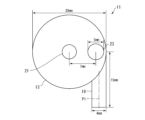
- FIG. 7 is a side view showing a swirl flow control valve according to a second embodiment of the present invention. It is an explanatory diagram for explaining the configuration and dimensions of the swirl flow control valve used in the experiment, and shows the swirl flow control valve from above with the upper end wall (second end wall) removed. ing.
- FIG. 2 is an explanatory diagram for explaining the configuration and dimensions of the swirl flow control valve used in the experiment, and shows the swirl flow control valve viewed from the side.
- FIG. 2 is a piping diagram showing the arrangement of a vortex flow rate control valve, measurement equipment, and adjustment equipment used in an experiment.
- the protrusion was placed at an angular position of 90° and displaced by distances of 3.5 mm, 5.5 mm, and 7.5 mm from the center of the vortex chamber, respectively. It is a line graph plotting the relationship between the protrusion length and the flow rate Q (flow rate from the outlet flow path) when the protrusion length is arranged.
- the protrusions were located at positions deviated from the center of the vortex chamber by distances of 3.5 mm, 5.5 mm, and 7.5 mm at an angular position of 180°. It is a line graph plotting the relationship between the protrusion length and the flow rate Q when the protrusion length is arranged.
- FIG. 14 is an explanatory diagram for explaining the protrusion of the vortex flow control valve used in the numerical simulation using the vortex flow control valve shown in FIG. 13; It shows.
- FIG. 14 is an explanatory diagram for explaining the protrusion of the vortex flow control valve used in the numerical simulation using the vortex flow control valve shown in FIG. 13; It shows.
- FIG. 14 is an explanatory diagram for explaining the protrusion of the vortex flow control valve used in the numerical simulation using the vortex flow control valve shown in FIG. It shows.
- a protrusion with a cross section of shape 1 is placed at an angular position of 90° and offset by a distance of 3.5 mm from the center of the vortex chamber.
- FIG. 3 is a bar graph showing a comparison of the flow rate difference ⁇ Q when the length of the protrusion part is changed from 0.5 mm to 3.5 mm for each shape of the protrusion part under the conditions of .
- a numerical simulation using the swirl type flow control valve shown in Fig. 13 under the condition that the protrusion is located at an angular position of 90° and a distance of 7.5 mm from the center of the swirl chamber, It is a bar graph showing a comparison of the flow rate difference ⁇ Q when the length of the protruding part is changed from 0.5 mm to 3.5 mm for each shape of the part.
- FIG. 13 In a numerical simulation using the vortex flow control valve shown in FIG.
- the protrusions with a cross section of shape 3 are located at angular positions of 90° at distances of 3.5 mm, 5.5 mm, and 7.5 mm from the center of the vortex chamber, respectively.
- 3 is a line graph plotting the relationship between the protruding length and the flow rate Q when the protruding portion is disposed at a position deviated by .
- the position of the inlet flow path relative to the center of the vortex chamber was changed under the condition that the protrusion having a cross section of shape 1 was placed at the center of the vortex chamber.
- a protrusion having a cross section of shape 1 is placed at an angular position of 90° and offset by 7.5 mm from the center of the swirl chamber.
- the flow rate difference ⁇ Q is compared when the length of the protruding portion is changed from 0.5 mm to 3.5 mm at each inlet flow path position. This is a bar graph shown.
- a protrusion having a cross section of shape 1 is placed at an angular position of 90° and offset by 7.5 mm from the center of the swirl chamber.
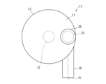
- the vortex flow rate control valve 11 includes a cylindrical circumferential wall 13 extending along the central axis, and a first end wall 15 and a second end wall 15 and second end walls provided at both ends of the circumferential wall 13 in the direction of the central axis. It includes an end wall 17, an inlet flow path 19, an outlet flow path 21, a protrusion 23, and a drive unit 25 that drives the protrusion 23.
- the first end wall 15 and the second end wall 17 have the same shape and are provided so as to close the end of the circumferential side wall 13 in the central axis direction. 15 and the second end wall 17 constitutes a vortex chamber 27.
- a center axis O of the vortex chamber which extends to connect the center of the first end wall 15 and the center of the second end wall 17 , coincides with the center axis of the circumferential wall 13 .
- the center of the 1st end wall 15 and the center of the 2nd end wall 17 mean the gravity center position of the 1st end wall 15 and the 2nd end wall 17, respectively.
- the first end wall 15 and the second end wall 17 are circular, and the circumferential wall 13 is cylindrical.
- the shapes of the first end wall 15 and the second end wall 17 are not limited to circular shapes, but may be elliptical, triangular, or square if a vortex can be generated in the vortex chamber 27. It can be any shape, such as a polygonal shape.
- the inlet flow path 19 extends along the inlet flow path center axis P1 perpendicular to the vortex chamber center axis O, and is open to the peripheral wall 13.
- the inlet flow path center axis P1 extends through the center of the cross section of the inlet flow path 19.
- the outlet flow path 21 extends from the vortex chamber 27 to the outside along an outlet flow path center axis P2 that is parallel to the vortex chamber center axis O, and is open to the first end wall 15 of the vortex chamber 27. .
- the outlet flow path center axis P2 extends through the center of the cross section of the outlet flow path 21.
- both the inlet channel 19 and the outlet channel 21 are constituted by circular tubes having a circular cross-sectional shape.
- the cross sections of the inlet flow path 19 and the outlet flow path 21 are not limited to circular shapes, but may also be polygonal shapes such as elliptical shapes or square shapes.
- the inlet flow path 19 is configured by a straight circular tube, but it may have another shape such as a nozzle shape as long as the fluid can flow into the vortex chamber 27. .
- the inlet flow path 19 is provided so that the center axis P1 of the inlet flow path passes through an eccentric position away from the center axis O of the vortex chamber. Therefore, the fluid flowing in from the inlet channel 19 hits the circumferential wall 13 in the vortex chamber 27 and flows along the circumferential wall 13 to generate a swirling flow, which turns into a vortex and flows toward the outlet channel 21 from the outlet channel 21. leak.
- the inlet flow path 19 is preferably provided so that the fluid flowing into the vortex chamber 27 from the inlet flow path 19 flows along the circumferential wall 13 in order to easily generate a swirling flow.
- the outlet flow path 21 can be formed at any point in the first end wall 15. It can be provided at any location. That is, the outlet flow path 21 is located at a position where the outlet flow path center axis P2 is distant from the inlet flow path center axis P1 so that the fluid that has flowed into the vortex chamber 27 from the inlet flow path 19 does not directly flow out from the outlet flow path 21. It is sufficient if it is provided so as to extend through the.
- the inlet flow path 19 extends in the tangential direction of the cylindrical circumferential wall 13 and is connected to the circumferential wall 13 such that the inlet flow path center axis P1 is parallel to the tangential line. flows from the inlet channel 19 into the vortex chamber 27 substantially tangentially to the circumferential wall 13 .
- the outlet flow path 21 is opened to the first end wall 15, and the outlet flow path center axis P2 passes through the center of the first end wall 15, that is, the outlet flow path center axis P2 is aligned with the vortex chamber center axis. It is provided so as to extend above O. With this configuration, the fluid flowing in from the inlet channel 19 flows along the circumferential wall 13 in the vortex chamber 27 to generate a swirling flow, and gradually approaches the center while spirally moving toward the outlet channel 21. It's flowing.
- the protruding part 23 is provided on the second end wall 17 so as to protrude into the vortex chamber 27 toward the first end wall 15, and is driven by the drive part 25 to move the center of the vortex chamber within the vortex chamber 27. It is movable along a movement axis extending parallel to the axis O. By moving the protrusion 23 within the vortex chamber 27 by the drive unit 25, the distance (i.e., the gap) between the top of the protrusion 23 extending from the second end wall 17 and the opposing first end wall 15 is reduced. ) can be changed.
- a cylinder mechanism is used as the drive unit 25, which can change the length of the protrusion 23 into the vortex chamber 27.
- the drive unit 25 is not limited to a cylinder mechanism, and moves the protrusion 23 within the vortex chamber 27 to connect the top of the protrusion 23 extending from the second end wall 17 and the first opposing part.
- the distance that is, the gap
- other appropriate mechanisms such as an electric actuator can be used.
- the drive unit can employ various drive methods such as a manual type, an air drive type, and an electric type.
- the protrusion 23 has a columnar shape, and the cross section of the protrusion 23 perpendicular to the movement axis can have any shape.
- the cross section of the protrusion 23 can be, for example, circular, elliptical, polygonal such as square, triangular, or diamond-shaped, or plate-shaped.
- the protrusion 23 has a cylindrical shape with a circular cross section.
- the protruding portion 23 can also have a conical shape or a polygonal pyramid shape, and a step or a groove may be provided on the circumferential side of the columnar or conical shape.
- the protrusion 23 is arranged so that at least a part of the protrusion 23 is connected to the inlet flow path into the vortex chamber 27 so that the swirling flow of the fluid flowing into the vortex chamber 27 from the inlet flow path 19 collides with the protrusion 23 more quickly. It is preferable that they be arranged so as to overlap on an extension of 19. However, since a vortex is generated in the vortex chamber 27 as described above, if the movement axis of the protrusion 23 is not provided so as to extend on the outlet flow path center axis P2, that is, the protrusion 23 is not connected to the outlet flow path 21. If they are not provided at opposing positions, they will collide with the vortex within the vortex chamber 27. Therefore, the position of the protrusion 23 is not particularly limited as long as it is offset from the position facing the outlet flow path 21.
- the inlet flow path 19 is provided so that the inlet flow path center axis P1 passes through an eccentric position away from the vortex chamber center axis O. Therefore, when the protrusion 23 does not protrude into the vortex chamber 27, the fluid flowing in from the inlet channel 19 generates a swirl flow within the vortex chamber 27, as shown in FIG. It heads toward the outlet channel 21 while winding up, and flows out from the outlet channel 21. On the other hand, when the protrusion 23 protrudes into the vortex chamber 27, the fluid that can flow through the gap between the top of the protrusion 23 and the first end wall 15 is limited to the flow shown in FIGS. As shown by line 29, the swirl continues to maintain the vortex.
- the fluid having the protrusion 23 on the streamline flows through the gap between the outer circumferential surface of the protrusion 23 and the circumferential side wall 13, as shown by the streamline 31 in FIGS. 4 and 5.
- the flow curves greatly inward along the circumferential surface of the protruding portion 23, or flows along the inner circumferential surface of the protruding portion 23 as shown by streamlines 33 in FIGS. 4 and 5.
- the flow curves inward significantly and flows through a short cut to the outlet flow path 21.
- the fluid that flows into the vortex chamber 27 from the inlet flow path 19, turns into a vortex flow, heads toward the outlet flow path 21, and flows out from the outlet flow path 21 produces a pressure loss corresponding to the distance traveled.
- the flow to the outlet flow path 21 is reduced.
- the ratio of the fluid flowing through the short cut increases, the pressure loss of the fluid flowing from the inlet channel 19 to the outlet channel 21 decreases as a whole, and the flow rate of the fluid flowing out from the outlet channel 21 increases. That is, as shown in FIG. 8, the protrusion 23 is moved in a direction in which the top of the protrusion 23 approaches the first end wall 15, so that the top of the protrusion 23 and the first end wall 15 are separated.
- the flow rate of fluid exiting the outlet channel 21 can be increased by reducing the gap between the protrusions 23 and the first end wall 15, while spacing the top of the projection 23 from the first end wall 15, as shown in FIG.
- the flow rate of the fluid flowing out from the outlet channel 21 can be reduced.
- the present inventor moved the protrusion 23 within the vortex chamber 27 so as to change the gap between the top of the protrusion 23 and the first end wall 15, thereby making it possible to contact the part that comes into contact with the target fluid. It has been found that the flow rate of the fluid flowing out from the outlet flow path 21 can be adjusted without providing a contact part, and it can function as a flow rate control valve.
- the flow rate adjustment by the protrusion 23 is performed so that the fluid flowing from the inlet channel 19 becomes a vortex in the vortex chamber 27 and flows toward the outlet channel 21, and the protrusion 23 obstructs this vortex.
- the rate at which the protrusion 23 obstructs the vortex flow could be changed by moving the protrusion 23 within the vortex chamber 27. Therefore, the shape of the vortex chamber 27 and the positions of the inlet channel 19 and the outlet channel 21 are not limited as long as a vortex can be generated in the vortex chamber 27, and as long as the protrusion 23 obstructs the vortex.
- the position of the protrusion 23 is not limited.
- the cross-sectional shape of the protrusion 23 is not limited either. That is, in the vortex flow control valve 11 according to the present invention, a wide range of combinations of configurations are possible.
- the protrusion 23 may be moved within the vortex chamber 27 to change the distance between the top of the protrusion 23 and the first end wall 15.
- the diaphragm 17' functions not only as the second end wall but also as a drive for driving the protrusion 23.
- the diaphragm 17' only needs to be able to move the protruding part 23 while supporting the protruding part 23, so only a part of the second end wall 17 is used as the diaphragm 17', and the diaphragm 17' protrudes into the vortex chamber 27.
- the portion 23 may be supported. Note that in FIG.
- the configuration of the vortex flow control valve 11' of the second embodiment is the same as the vortex flow control valve 11' of the first embodiment, except that the protruding part 23 is moved within the vortex chamber 27 by a diaphragm 17' instead of the drive part 25.
- the operation of the swirl flow control valve 11' of the second embodiment is also the same as that of the swirl flow control valve 11 of the first embodiment. The same applies to the point that the flow rate is adjusted by changing the distance (gap) between the projection 15 and the top of the protrusion 23. Therefore, detailed explanation of the configuration and operation will be omitted here.
- the swirl chamber 27 has a cylindrical shape with a diameter of 20 mm and a height of 4 mm, and a diameter of 4 mm and a length of 15 mm.
- a circular tube-shaped inlet flow path 19 is connected to the circumferential wall 13 so as to extend tangentially, and a circular tube-shaped outlet flow path 21 with a diameter of 4 mm and a length of 10 mm extends along the center axis O of the vortex chamber.
- the road center axis P2 is connected to the first end wall 15 such that it passes through the center of the first end wall 15.
- the protrusion 23 has a cylindrical shape with a diameter of 5 mm, and is deviated by 7 mm from the center of the vortex chamber 27 toward the inlet channel 19 in a direction perpendicular to the inlet channel center axis P1 of the inlet channel 19. It is placed in the specified position. Further, as shown in FIG.
- the pressure difference between the upstream pressure PU and the downstream pressure PD of the swirl flow control valve 11 is adjusted by a pressure regulation valve 35 disposed upstream of the swirl flow control valve 11, while changing the length of the protrusion 23 of the swirl flow control valve 11, the flow rate is measured by a flow meter 37 disposed upstream of the swirl flow control valve 11 (specifically, downstream of the pressure control valve 35).
- the upstream pressure PU and the downstream pressure PD were measured by an upstream pressure gauge 39 and a downstream pressure gauge 41 installed upstream and downstream of the swirl flow control valve 11, respectively.
- FIG. 12 is a graph plotting the relationship between the length (mm) of the protrusion 23 and the flow rate Q (L/min) obtained through an experiment.
- the symbol “ ⁇ ” indicates that the differential pressure between the upstream pressure PU and the downstream pressure PD is 0.05 MPa
- the symbol “ ⁇ ” indicates that the differential pressure is 0.1 MPa
- the symbol “ ⁇ ” indicates that the differential pressure is 0.05 MPa.
- the relationship between the length (mm) of the protrusion 23 and the flow rate Q (L/min) in the case of 2 MPa is shown.
- FIG. 12 under any differential pressure conditions, there is a correlation between the length of the protrusion 23 and the flow rate Q, and the longer the protrusion 23 is, the larger the flow rate Q is. Therefore, it was confirmed that by changing the length of the protrusion 23, the flow rate Q can be changed and the flow rate Q can be adjusted and controlled. It was also confirmed that the flow rate Q increased as the differential pressure increased.
- the simulation is performed in such a manner that the vortex chamber 27 has a cylindrical shape with a diameter of 20 mm and a height of 4 mm, and the inlet channel center axis P1 is separated from the center of the vortex chamber 27 by 7.5 mm.
- the inlet channel is shaped like a circular tube with a diameter of 4 mm so that the right end of the inlet channel 19 in the figure passes through the center of the vortex chamber 27 and is located 15 mm away from a line perpendicular to the center axis P1 of the inlet channel.
- a circular tube-shaped outlet passage 21 with a diameter of 4 mm and a length of 10 mm extends along the swirl chamber center axis O, and the outlet passage center axis P 2 is connected to the center of the first end wall 15 . This is done under the condition that it is connected to the first end wall 15 so as to pass through.
- the protrusion 23 is assumed to have a cylindrical shape with a diameter of 4 mm, and its central axis is located at various angular positions (0°, 45°, 90°, 135°, 180°, 270°) of the vortex chamber 27. They are provided at positions offset from the center by various distances (3.5 mm, 5.5 mm, 7.5 mm) toward the peripheral wall 13, and the length is from 0.5 mm to 3.5 mm.
- the amount of change in the flow rate Q (hereinafter referred to as "flow rate difference ⁇ Q”) was determined by changing the flow rate within the range of . As shown in FIG.
- the "angular position" of the protrusion 23 is parallel to the center axis P1 of the inlet flow path and toward the side closer to the inlet flow path 19 passing through the center of the vortex chamber 27.
- the direction of the extending axis is 0°, and it is defined as the angle that the axis extending from the center of the vortex chamber 27 through the center of the protrusion 23 makes with respect to the 0° axis counterclockwise around the center of the vortex chamber 27. .
- FIG. 14 shows the relationship between the angular position (°) of the protrusion 23 and the flow rate difference ⁇ Q (L/min) obtained when the length of the protrusion 23 was changed from 0.5 mm to 3.5 mm in the simulation.
- This is a graph plotting.
- the symbol " ⁇ " indicates that the center axis of the protrusion 23 is placed at a position offset by a distance of 3.5 mm from the center of the vortex chamber 27, and the symbol “ ⁇ ” indicates that the center axis of the protrusion 23 is located at a position eccentric from the center of the vortex chamber 27.
- ⁇ indicates the case where the center axis of the protrusion 23 is placed at a position eccentric by a distance of 7.5 mm from the center of the vortex chamber 27.
- the relationship between the angular position (°) of the protrusion 23 and the flow rate difference ⁇ Q (L/min) is shown.
- the inlet channel 19 is connected to the circumferential wall 13 so as to extend generally tangentially to the circumferential wall 13, and the outlet channel 21 is connected to the first end wall 15 so as to extend from the center of the vortex chamber 27.
- ⁇ Q can be caused.
- 15 and 16 show the protrusions obtained when the protrusions 23 were provided at angular positions of 90° and 180° and the length of the protrusions 23 was varied from 0.5 mm to 3.5 mm in the simulation, respectively.
- 23 is a line graph plotting the relationship between length (mm) and flow rate (L/min).
- the symbol " ⁇ " indicates that the central axis of the protrusion 23 is located at an angular position of 90 degrees and is eccentric by 3.5 mm from the center of the vortex chamber 27, and the symbol " ⁇ " indicates the center of the protrusion 23.
- the symbol “ ⁇ ” means that the central axis of the protrusion 23 is located at an angular position of 90° and located 7 mm from the center of the vortex chamber 27.
- the relationship between the length (mm) of the protrusion 23 and the flow rate (L/min) when the protrusion 23 is placed at a position eccentric by .5 mm is shown.
- FIG. 1 In addition, in FIG. 1
- the symbol “ ⁇ ” indicates that the central axis of the protrusion 23 is located at an angular position of 180 degrees and is eccentric by 3.5 mm from the center of the vortex chamber 27, and the symbol “ ⁇ ” indicates that the protrusion 23 If the central axis of the protrusion 23 is at an angular position of 180° and the center axis of the protrusion 23 is located at a position offset by 5.5 mm from the center of the vortex chamber 27, the symbol “ ⁇ ” indicates that the central axis of the protrusion 23 is at an angular position of 180° and the center of the vortex chamber 27
- the inlet channel 19 is connected to the circumferential wall 13 so as to extend generally tangentially to the circumferential wall 13
- the outlet channel 21 is connected to the first end wall 15 so as to extend from the center of the vortex chamber 27. Under these conditions, it is possible to adjust and control the flow rate Q by changing the length of the protrusion 23, regardless of the position of the protrusion 23.
- the cross-sectional shape 1 is a circular shape with a diameter of 4 mm, as shown in FIG. 17A
- the cross-sectional shape 2 is a diamond shape with a diagonal length of 4 mm, as shown in FIG. 17B.
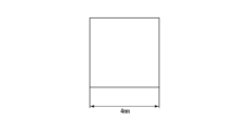
- the cross-sectional shape 3 is a square shape with one side of 4 mm, as shown in FIG. 17C.
- the protrusion 23 was arranged in the direction in which the vortex first hits the corner of the diamond shape, and in the case of cross-sectional shape 3, the protrusion 23 was arranged in the direction in which the vortex was received by the square surface.
- FIG. 18 shows the results obtained when the protrusion 23 is provided so that the central axis is located at an angular position of 90° and offset by 3.5 mm from the center of the vortex chamber 27, and FIG. This is the result obtained when the protrusion 23 is provided so that the central axis is located at an angular position of 90° and offset by 7.5 mm from the center of the vortex chamber 27.
- the inlet channel 19 is connected to the circumferential wall 13 so as to extend generally tangentially to the circumferential wall 13, and the outlet channel 21 is connected to the first end wall 15 so as to extend from the center of the vortex chamber 27. It can be seen that under the condition that the protrusion 23 is connected to the flow rate Q, the flow rate Q can be changed and the flow rate difference ⁇ Q can be generated by changing the length of the protrusion 23, regardless of the cross-sectional shape of the protrusion 23.
- the flow rate difference ⁇ Q depending on the position of the protrusion 23 including the result when the protrusion 23, which is not shown here, is placed at an angular position of 90° and at a position offset by 5.5 mm from the center of the vortex chamber 27. From the comparison, the flow rate difference ⁇ Q is larger for shape 2 (diamond-shaped cross section) than shape 1 (circular cross section), and the flow rate difference ⁇ Q is even larger for shape 3 (square cross section) than shape 2. I found out that it is.
- FIG. 20 shows a protrusion 23 obtained when a protrusion 23 having a cross section of shape 3 is provided at an angular position of 90° and the length of the protrusion 23 is varied from 0.5 mm to 3.5 mm in the simulation. It is a line graph plotting the relationship between the length (mm) and the flow rate Q (L/min).
- the symbol " ⁇ " indicates that the center axis of the protrusion 23 is located at an angular position of 90 degrees and is eccentric by 3.5 mm from the center of the vortex chamber 27, and the symbol “ ⁇ " indicates the center of the protrusion 23.
- the symbol “ ⁇ ” means that the central axis of the protrusion 23 is located at an angular position of 90° and located 7 mm from the center of the vortex chamber 27.
- the relationship between the length (mm) of the protrusion 23 and the flow rate (L/min) when the protrusion 23 is placed at a position eccentric by .5 mm is shown.
- the inlet channel 19 is connected to the circumferential wall 13 so as to extend generally tangentially to the circumferential wall 13, and the outlet channel 21 is connected to the first end wall 15 so as to extend from the center of the vortex chamber 27. Under these conditions, it is possible to adjust and control the flow rate Q by changing the length of the protrusion 23, regardless of the cross-sectional shape of the protrusion 23.
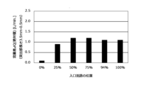
- the position of the inlet channel 19 is determined by the center of the vortex chamber 27 and the inlet flow of the inlet channel 19 relative to the difference between the diameter of the cylindrical vortex chamber 27 and the diameter of the circular tube-shaped inlet channel 19 divided by 2. It was defined as the ratio (%) of the distance to the road center axis P1. This is because the inlet channel 19 can be provided close to the circumferential wall 13 only up to a position where the inlet channel center axis P1 is separated from the circumferential wall 13 by the radius of the inlet channel 19.
- the cylindrical protrusion 23 with a diameter of 4 mm is provided at an angular position of 90°, and the outlet flow path 21 is connected to the first end wall 15 so as to extend from the center of the vortex chamber 27.
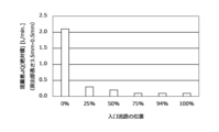
- simulations were performed for cases where the position of the inlet flow path 19 with respect to the outlet flow path 21 was 0%, 25%, 50%, 75%, 94%, and 100%.
- FIGS. 21 to 23 show various positions of the protrusion 23 when the position of the inlet channel 19 relative to the outlet channel 21 is changed to 0%, 25%, 50%, 75%, 94%, and 100%.
- ⁇ Q flow rate differences
- FIG. 21 shows the results obtained when the protrusion 23 is provided so that the central axis is located at the center of the vortex chamber 27, and
- FIG. 23 shows the results obtained when the protrusion 23 is provided at a position eccentric by 5.5 mm from the center, and FIG. This is the result obtained when the protrusion 23 was provided so as to be placed at a position eccentric by .5 mm.
- the white bar graphs represent that when the protrusion 23 is short, the flow rate is relatively large, and when the protrusion 23 is long, the flow rate is relatively small.
- the black bar graph represents that when the protrusion 23 is short, the flow rate is relatively small, and when the protrusion 23 is long, the flow rate is relatively large.
- the protrusion 23 is eccentric from the center of the vortex chamber 27. , regardless of the position of the inlet flow path 19, except when the inlet flow path center axis P1 of the inlet flow path 19 passes through the center of the vortex chamber 27 (that is, when the position of the inlet flow path 19 is 0%). First, it can be seen that by changing the length of the protrusion 23, the flow rate Q can be changed and a significant flow rate difference ⁇ Q can be produced.
- the protruding part 23 when the protruding part 23 is provided at the center of the vortex chamber 27 (that is, the protruding part 23 is provided at an angular position of 90 degrees and a distance of 0 mm eccentric from the center of the vortex chamber 27). Regardless of the position of the protrusion 23, the longer the protrusion 23, the lower the flow rate. This means that under the condition that the outlet channel 21 is connected to the first end wall 15 so as to extend from the center of the vortex chamber 27, if the protrusion 23 is provided at the center of the vortex chamber 27, the protrusion 23 is disposed facing the outlet flow path 21, and the longer the protrusion 23 becomes, the more the flow path area for the fluid flowing into the outlet flow path 21 is reduced.
- the protrusion 23 is extended from the center of the vortex chamber 27.
- the inlet channel 19 is located at a position from 50% to 100%.
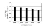
- the position of the outlet channel 21 was defined by the angular position defined similarly to the angular position of the protrusion 23 and the distance X from the center of the vortex chamber 27, as shown in FIG.
- the position of the outlet flow path 21 indicated by a two-dot chain line in FIG. 13 is expressed as a position at a distance X from an angular position of 0°.
- the inlet flow path 19 was provided such that the inlet flow path center axis P1 was located at a distance of 8 mm from the center of the vortex chamber 27, and the cylindrical protrusion 23 with a diameter of 4 mm was located at an angular position of 90°.
- the vortex chamber 27 was provided at a position offset from the center of the vortex chamber 27 by a distance of 7.5 mm.
- FIGS. 24 and 25 show different angular positions of the outlet flow path 21 when the distance X of the outlet flow path 21 from the center of the vortex chamber 27 is changed to 0 mm, 0.25 mm, 0.5 mm, 1 mm, and 2 mm.
- ⁇ Q flow rate differences
- FIG. 24 shows the results obtained when the outlet flow path 21 is provided at an angular position of 90°
- FIG. 25 shows the results obtained when the outlet flow path 21 is provided at an angular position of 180°. be.
- the inlet flow path 19 is provided such that the inlet flow path center axis P1 is located at a distance of 8 mm from the center of the vortex chamber 27, and the cylindrical protrusion 23 with a diameter of 4 mm is provided.
- the flow rate Q can be adjusted by changing the length of the protrusion 23 regardless of the position of the outlet flow path 21. It can be seen that it is possible to generate a flow rate difference ⁇ Q by changing ⁇ Q. That is, it is possible to adjust the flow rate Q by changing the length of the protrusion 23 without depending on the outlet channel 21.
- FIG. 26 shows the results when the length of the protrusion 23 is changed from 0.5 mm to 3.5 mm when the outlet flow path 21 is provided eccentrically from the center of the vortex chamber 27 at an angular position of 90° in the simulation. It is a line graph plotting the relationship between the obtained length (mm) of the protrusion 23 and the flow rate Q (L/min).
- the symbol “ ⁇ ” indicates that the outlet channel 21 is provided at the center of the vortex chamber 27, and the symbol “ ⁇ ” indicates that the outlet channel 21 is located at an angular position of 90° by 0.25 mm from the center of the vortex chamber 27.
- the symbol " ⁇ " indicates the exit flow when the outlet flow path 21 is installed at an angular position of 90° and an eccentric position of 0.5 mm from the center of the vortex chamber 27. If the channel 21 is provided at an angular position of 90° and offset by 1 mm from the center of the swirl chamber 27, the symbol “*" indicates that the outlet channel 21 is provided at an angular position of 90° and offset by 2 mm from the center of the swirl chamber 27.
- the relationship between the length (mm) of the protrusion 23 and the flow rate (L/min) when the protrusion 23 is provided at a certain position is shown.
- the inlet flow path 19 is provided such that the center axis P1 of the inlet flow path is located at a distance of 8 mm from the center of the vortex chamber 27, and the cylindrical protrusion 23 with a diameter of 4 mm is located at an angular position of 90°.
- the outlet flow path 21 is provided at an eccentric position of 7.5 mm from the center of the vortex chamber 27 and the outlet flow path 21 is provided at an angular position of 90°.
- the present invention is not limited to the illustrated embodiments.
- a cylindrical vortex chamber 27 is employed, but if a vortex can be generated within the vortex chamber 27, an elliptical or polygonal cylindrical vortex chamber may be employed. is also possible.
- the flow rate Q can be changed by changing the gap between the top of the protrusion 23 and the end wall facing it, the protrusion 23 is located not at the second end wall 17 but at the first end. It may be provided on the wall 15.
Landscapes
- Engineering & Computer Science (AREA)
- General Engineering & Computer Science (AREA)
- Mechanical Engineering (AREA)
- Physics & Mathematics (AREA)
- Fluid Mechanics (AREA)
- General Physics & Mathematics (AREA)
- Lift Valve (AREA)
Priority Applications (4)
| Application Number | Priority Date | Filing Date | Title |
|---|---|---|---|
| US18/868,173 US20250327528A1 (en) | 2022-05-23 | 2023-05-22 | Vortex-type flow control valve |
| KR1020247038193A KR20250016109A (ko) | 2022-05-23 | 2023-05-22 | 와류형 유량조절밸브 |
| CN202380032618.3A CN118922660A (zh) | 2022-05-23 | 2023-05-22 | 涡流型流量调节阀 |
| JP2024523290A JPWO2023228915A1 (https=) | 2022-05-23 | 2023-05-22 |
Applications Claiming Priority (2)
| Application Number | Priority Date | Filing Date | Title |
|---|---|---|---|
| JP2022084137 | 2022-05-23 | ||
| JP2022-084137 | 2022-05-23 |
Publications (1)
| Publication Number | Publication Date |
|---|---|
| WO2023228915A1 true WO2023228915A1 (ja) | 2023-11-30 |
Family
ID=88919274
Family Applications (1)
| Application Number | Title | Priority Date | Filing Date |
|---|---|---|---|
| PCT/JP2023/019009 Ceased WO2023228915A1 (ja) | 2022-05-23 | 2023-05-22 | 渦流型流量調節弁 |
Country Status (6)
| Country | Link |
|---|---|
| US (1) | US20250327528A1 (https=) |
| JP (1) | JPWO2023228915A1 (https=) |
| KR (1) | KR20250016109A (https=) |
| CN (1) | CN118922660A (https=) |
| TW (1) | TW202409457A (https=) |
| WO (1) | WO2023228915A1 (https=) |
Cited By (1)
| Publication number | Priority date | Publication date | Assignee | Title |
|---|---|---|---|---|
| GB2642072A (en) * | 2024-06-22 | 2025-12-31 | Ian Taylor Sean | Vortex flow control device for stormwater management |
Citations (3)
| Publication number | Priority date | Publication date | Assignee | Title |
|---|---|---|---|---|
| JP2003020959A (ja) * | 2001-07-09 | 2003-01-24 | Ishikawajima Harima Heavy Ind Co Ltd | 緊急減速機能付き燃料流量制御装置 |
| JP2004136085A (ja) * | 2002-09-27 | 2004-05-13 | Toto Ltd | マッサージノズル及びマッサージシステム |
| JP2005535445A (ja) * | 2002-08-15 | 2005-11-24 | エンジニアリング ヴォーテックス ソリューションズ プロプライエタリー リミテッド | 噴射ノズルを通過する流動体の流れを制御する器具 |
Family Cites Families (1)
| Publication number | Priority date | Publication date | Assignee | Title |
|---|---|---|---|---|
| JPS5144880U (https=) | 1974-09-30 | 1976-04-02 |
-
2023
- 2023-05-19 TW TW112118731A patent/TW202409457A/zh unknown
- 2023-05-22 KR KR1020247038193A patent/KR20250016109A/ko active Pending
- 2023-05-22 JP JP2024523290A patent/JPWO2023228915A1/ja active Pending
- 2023-05-22 CN CN202380032618.3A patent/CN118922660A/zh active Pending
- 2023-05-22 US US18/868,173 patent/US20250327528A1/en active Pending
- 2023-05-22 WO PCT/JP2023/019009 patent/WO2023228915A1/ja not_active Ceased
Patent Citations (3)
| Publication number | Priority date | Publication date | Assignee | Title |
|---|---|---|---|---|
| JP2003020959A (ja) * | 2001-07-09 | 2003-01-24 | Ishikawajima Harima Heavy Ind Co Ltd | 緊急減速機能付き燃料流量制御装置 |
| JP2005535445A (ja) * | 2002-08-15 | 2005-11-24 | エンジニアリング ヴォーテックス ソリューションズ プロプライエタリー リミテッド | 噴射ノズルを通過する流動体の流れを制御する器具 |
| JP2004136085A (ja) * | 2002-09-27 | 2004-05-13 | Toto Ltd | マッサージノズル及びマッサージシステム |
Cited By (1)
| Publication number | Priority date | Publication date | Assignee | Title |
|---|---|---|---|---|
| GB2642072A (en) * | 2024-06-22 | 2025-12-31 | Ian Taylor Sean | Vortex flow control device for stormwater management |
Also Published As
| Publication number | Publication date |
|---|---|
| US20250327528A1 (en) | 2025-10-23 |
| TW202409457A (zh) | 2024-03-01 |
| CN118922660A (zh) | 2024-11-08 |
| JPWO2023228915A1 (https=) | 2023-11-30 |
| KR20250016109A (ko) | 2025-02-03 |
Similar Documents
| Publication | Publication Date | Title |
|---|---|---|
| JP4979197B2 (ja) | 高リカバリ音速ガス弁 | |
| US12449063B2 (en) | Fluid flow control devices and systems, and methods of flowing fluids therethrough | |
| US10427501B2 (en) | Outlet device | |
| KR102208101B1 (ko) | 유체 제어 장치 | |
| CN1767891A (zh) | 流体混合装置 | |
| WO2023228915A1 (ja) | 渦流型流量調節弁 | |
| EP3026312B1 (en) | Control valve | |
| AU2005210939B2 (en) | Expansion valve of refrigerating apparatus | |
| CN112049972B (zh) | 用于控制过程流体流动的提升阀 | |
| JP5986093B2 (ja) | 一体形成型ブースト低減機能を有する弁箱 | |
| WO2023228916A1 (ja) | 渦流型流量調節弁 | |
| CN114072608B (zh) | 管接头装置 | |
| EP0503462A2 (en) | Fluidic vibrating type flowmeter | |
| RU2514328C1 (ru) | Дроссельно-регулирующее устройство | |
| US8556226B2 (en) | Valve with the device enhancing capability of its closure member and related seat ring to resist erosion | |
| US20230048962A1 (en) | Fluid flow control devices and systems, and methods of flowing fluids | |
| JP7457194B1 (ja) | 渦流式流体混合器 | |
| WO2016135823A1 (ja) | 流体制御弁 | |
| JP2015052389A (ja) | 流体制御弁 | |
| JP7457193B1 (ja) | 渦流式流体混合器 | |
| KR20250092718A (ko) | 압력조절의 유연성을 갖는 플래퍼 노즐의 밸브 포지셔너 | |
| KR20220013044A (ko) | 질량 유량계 | |
| WO2019215990A1 (ja) | 旋回流調整装置 | |
| JP2016084788A (ja) | 主蒸気弁、及び蒸気タービン |
Legal Events
| Date | Code | Title | Description |
|---|---|---|---|
| 121 | Ep: the epo has been informed by wipo that ep was designated in this application |
Ref document number: 23811787 Country of ref document: EP Kind code of ref document: A1 |
|
| ENP | Entry into the national phase |
Ref document number: 2024523290 Country of ref document: JP Kind code of ref document: A |
|
| WWE | Wipo information: entry into national phase |
Ref document number: 202380032618.3 Country of ref document: CN |
|
| WWE | Wipo information: entry into national phase |
Ref document number: 18868173 Country of ref document: US |
|
| NENP | Non-entry into the national phase |
Ref country code: DE |
|
| WWP | Wipo information: published in national office |
Ref document number: 1020247038193 Country of ref document: KR |
|
| 122 | Ep: pct application non-entry in european phase |
Ref document number: 23811787 Country of ref document: EP Kind code of ref document: A1 |
|
| WWP | Wipo information: published in national office |
Ref document number: 18868173 Country of ref document: US |