WO2023228854A1 - 連結車両の制御装置、連結車両の制御方法、および連結車両の制御プログラム - Google Patents
連結車両の制御装置、連結車両の制御方法、および連結車両の制御プログラム Download PDFInfo
- Publication number
- WO2023228854A1 WO2023228854A1 PCT/JP2023/018563 JP2023018563W WO2023228854A1 WO 2023228854 A1 WO2023228854 A1 WO 2023228854A1 JP 2023018563 W JP2023018563 W JP 2023018563W WO 2023228854 A1 WO2023228854 A1 WO 2023228854A1
- Authority
- WO
- WIPO (PCT)
- Prior art keywords
- angle
- target
- steering angle
- predicted trajectory
- trailer
- Prior art date
- Legal status (The legal status is an assumption and is not a legal conclusion. Google has not performed a legal analysis and makes no representation as to the accuracy of the status listed.)
- Ceased
Links
Images


Classifications
-
- B—PERFORMING OPERATIONS; TRANSPORTING
- B62—LAND VEHICLES FOR TRAVELLING OTHERWISE THAN ON RAILS
- B62D—MOTOR VEHICLES; TRAILERS
- B62D15/00—Steering not otherwise provided for
- B62D15/02—Steering position indicators ; Steering position determination; Steering aids
- B62D15/027—Parking aids, e.g. instruction means
- B62D15/0275—Parking aids, e.g. instruction means by overlaying a vehicle path based on present steering angle over an image without processing that image
-
- B—PERFORMING OPERATIONS; TRANSPORTING
- B60—VEHICLES IN GENERAL
- B60D—VEHICLE CONNECTIONS
- B60D1/00—Traction couplings; Hitches; Draw-gear; Towing devices
- B60D1/24—Traction couplings; Hitches; Draw-gear; Towing devices characterised by arrangements for particular functions
- B60D1/245—Traction couplings; Hitches; Draw-gear; Towing devices characterised by arrangements for particular functions for facilitating push back or parking of trailers
-
- B—PERFORMING OPERATIONS; TRANSPORTING
- B60—VEHICLES IN GENERAL
- B60D—VEHICLE CONNECTIONS
- B60D1/00—Traction couplings; Hitches; Draw-gear; Towing devices
- B60D1/58—Auxiliary devices
- B60D1/62—Auxiliary devices involving supply lines, electric circuits or the like
-
- B—PERFORMING OPERATIONS; TRANSPORTING
- B60—VEHICLES IN GENERAL
- B60K—ARRANGEMENT OR MOUNTING OF PROPULSION UNITS OR OF TRANSMISSIONS IN VEHICLES; ARRANGEMENT OR MOUNTING OF PLURAL DIVERSE PRIME-MOVERS IN VEHICLES; AUXILIARY DRIVES FOR VEHICLES; INSTRUMENTATION OR DASHBOARDS FOR VEHICLES; ARRANGEMENTS IN CONNECTION WITH COOLING, AIR INTAKE, GAS EXHAUST OR FUEL SUPPLY OF PROPULSION UNITS IN VEHICLES
- B60K35/00—Instruments specially adapted for vehicles; Arrangement of instruments in or on vehicles
- B60K35/20—Output arrangements, i.e. from vehicle to user, associated with vehicle functions or specially adapted therefor
- B60K35/21—Output arrangements, i.e. from vehicle to user, associated with vehicle functions or specially adapted therefor using visual output, e.g. blinking lights or matrix displays
- B60K35/22—Display screens
-
- B—PERFORMING OPERATIONS; TRANSPORTING
- B60—VEHICLES IN GENERAL
- B60K—ARRANGEMENT OR MOUNTING OF PROPULSION UNITS OR OF TRANSMISSIONS IN VEHICLES; ARRANGEMENT OR MOUNTING OF PLURAL DIVERSE PRIME-MOVERS IN VEHICLES; AUXILIARY DRIVES FOR VEHICLES; INSTRUMENTATION OR DASHBOARDS FOR VEHICLES; ARRANGEMENTS IN CONNECTION WITH COOLING, AIR INTAKE, GAS EXHAUST OR FUEL SUPPLY OF PROPULSION UNITS IN VEHICLES
- B60K35/00—Instruments specially adapted for vehicles; Arrangement of instruments in or on vehicles
- B60K35/20—Output arrangements, i.e. from vehicle to user, associated with vehicle functions or specially adapted therefor
- B60K35/28—Output arrangements, i.e. from vehicle to user, associated with vehicle functions or specially adapted therefor characterised by the type of the output information, e.g. video entertainment or vehicle dynamics information; characterised by the purpose of the output information, e.g. for attracting the attention of the driver
-
- B—PERFORMING OPERATIONS; TRANSPORTING
- B60—VEHICLES IN GENERAL
- B60W—CONJOINT CONTROL OF VEHICLE SUB-UNITS OF DIFFERENT TYPE OR DIFFERENT FUNCTION; CONTROL SYSTEMS SPECIALLY ADAPTED FOR HYBRID VEHICLES; ROAD VEHICLE DRIVE CONTROL SYSTEMS FOR PURPOSES NOT RELATED TO THE CONTROL OF A PARTICULAR SUB-UNIT
- B60W50/00—Details of control systems for road vehicle drive control not related to the control of a particular sub-unit, e.g. process diagnostic or vehicle driver interfaces
- B60W50/0097—Predicting future conditions
-
- B—PERFORMING OPERATIONS; TRANSPORTING
- B62—LAND VEHICLES FOR TRAVELLING OTHERWISE THAN ON RAILS
- B62D—MOTOR VEHICLES; TRAILERS
- B62D13/00—Steering specially adapted for trailers
- B62D13/06—Steering specially adapted for trailers for backing a normally drawn trailer
-
- B—PERFORMING OPERATIONS; TRANSPORTING
- B62—LAND VEHICLES FOR TRAVELLING OTHERWISE THAN ON RAILS
- B62D—MOTOR VEHICLES; TRAILERS
- B62D15/00—Steering not otherwise provided for
- B62D15/02—Steering position indicators ; Steering position determination; Steering aids
- B62D15/027—Parking aids, e.g. instruction means
- B62D15/0285—Parking performed automatically
-
- G—PHYSICS
- G06—COMPUTING OR CALCULATING; COUNTING
- G06T—IMAGE DATA PROCESSING OR GENERATION, IN GENERAL
- G06T19/00—Manipulating three-dimensional [3D] models or images for computer graphics
- G06T19/006—Mixed reality
Definitions
- the present disclosure relates to a coupled vehicle control device, a coupled vehicle control method, and a coupled vehicle control program.
- Patent Document 1 listed below describes a control device that displays the time until the hitch angle recovers to zero in a coupled vehicle.
- One aspect of the present disclosure provides a control device for a coupled vehicle that includes a tractor and a trailer towed by the tractor.
- the control device is configured to execute state quantity acquisition processing, predicted trajectory information calculation processing, and display processing.
- the state quantity acquisition process is a process of acquiring the state quantity of the connected vehicle.
- the predicted trajectory information calculation process is a process of calculating predicted trajectory information of the trailer according to the state quantity.
- the display process is a process of displaying the predicted trajectory information by operating a display device.
- Another aspect of the present disclosure provides a method for controlling a coupled vehicle that includes a tractor and a trailer towed by the tractor.
- the control method includes the steps of executing state quantity acquisition processing, predicted trajectory information calculation processing, and display processing.
- the state quantity acquisition process is a process of acquiring the state quantity of the connected vehicle.
- the predicted trajectory information calculation process is a process of calculating predicted trajectory information of the trailer according to the state quantity.
- the display process is a process of displaying the predicted trajectory information by operating a display device.
- the control program is a program that causes a computer to execute state quantity acquisition processing, predicted trajectory information calculation processing, and display processing.
- the state quantity acquisition process is a process of acquiring the state quantity of the connected vehicle.
- the predicted trajectory information calculation process is a process of calculating predicted trajectory information of the trailer according to the state quantity.
- the display process is a process of displaying the predicted trajectory information by operating a display device.
- FIG. 1 is a perspective view showing the configuration of a coupled vehicle according to an embodiment.
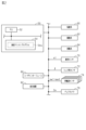
- FIG. 2 is a block diagram showing the configuration of the control system according to the embodiment.
- FIG. 3 is a diagram illustrating backward control of the coupled vehicle according to the embodiment.
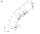
- FIG. 4 is a diagram showing a model of a coupled vehicle according to the same embodiment.
- FIG. 5 is a flowchart showing the procedure of processing executed by the control device according to the embodiment.
- FIG. 6 is a flowchart showing the procedure of processing executed by the control device according to the embodiment.
- FIGS. 7A and 7B are diagrams illustrating a method for displaying predicted trajectories.
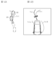
- 8A and 8B are diagrams showing display examples according to the same embodiment.
- 9A and 9B are diagrams showing display examples according to the same embodiment.
- FIG. 10A and FIG. 10B are diagrams showing display examples according to the same embodiment.
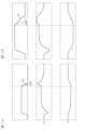
- FIGS. 11A and 11B are time charts illustrating virtual steering angle control according to the embodiment.
- 12A and 12B are diagrams showing display examples according to a modification of the above embodiment.
- 13A and 13B are diagrams showing display examples according to a modification of the above embodiment.
- 14A and 14B are diagrams showing display examples according to a modification of the above embodiment.
- the coupled vehicle 10 includes a tractor 20 and a trailer 30.
- the tractor 20 includes front wheels 22 and rear wheels 24.
- the front wheels 22 include two wheels, a right front wheel and a left front wheel
- the rear wheels 24 include two wheels, a right rear wheel and a left rear wheel.
- a box-shaped trailer is illustrated as the trailer 30.
- Trailer 30 has wheels 32 .
- the wheels 32 include two wheels, a right wheel and a left wheel.
- the trailer 30 is connected to the rear of the tractor 20 via a ball joint 40.
- the ball joint 40 is a member that rotatably connects the trailer 30 to the tractor 20 about a shaft 42 .
- the shaft 42 extends along the height direction of the tractor 20.
- FIG. 2 shows some of the members included in the tractor 20.
- the tractor 20 includes a control device 50.
- the control device 50 operates the steering system 60, the drive system 62, and the braking system 64 in order to control the control amount of the coupled vehicle 10 that is the object of control.
- the controlled variables include vehicle speed, traveling direction, hitch angle, and the like.
- the hitch angle is an angle between the longitudinal direction of the tractor 20 and the longitudinal direction of the trailer 30.
- the steering system 60 includes a steering actuator that steers the steered wheels.
- the steered wheel is, for example, the front wheel 22 shown in FIG.
- the steering system 60 may include a steering control device that operates a steering actuator.
- the control device 50 operates the steering system 60 means that the control device 50 outputs a command signal to the steering control device.
- the drive system 62 includes at least one of an internal combustion engine and a rotating electric machine as a thrust generating device of the vehicle.
- the drive system 62 may include a drive control device that controls an internal combustion engine and a rotating electric machine.
- the control device 50 operates the drive system 62 means that the control device 50 outputs a command signal to the drive control device.
- the braking system 64 includes at least one of two devices: a device that decelerates the rotation of the wheels by frictional force, and a device that decelerates the rotation of the wheels by converting the power of the wheels into electrical energy.
- the device that decelerates the rotation of the wheels by converting it into electrical energy may be shared with the rotating electric machine of the drive system.
- the brake system 64 may include a brake control device that controls a device that decelerates the rotation of the wheels. In that case, "the control device 50 operates the brake system 62" means that the control device 50 outputs a command signal to the brake control device.
- the control device 50 refers to the steered angle ⁇ 1 of the steered wheels detected by the steered angle sensor 70 in order to control the control amount.
- the steering angle ⁇ 1 is a value in which one of the right turning and left turning has a positive sign and the other sign has a negative sign.
- the steering angle ⁇ 1 is the turning angle of the tire.
- the steering angle sensor 70 may be a sensor that detects the pinion angle.
- the control device 50 executes a process of converting the pinion angle into a turning angle of the tire.
- the tire turning angle will be regarded as the detected value of the steering angle sensor 70 even if the tire turning angle is obtained by the above converting process.
- the control device 50 also refers to the hitch angle ⁇ detected by the hitch angle sensor 72.
- the hitch angle ⁇ can take either a positive or negative sign depending on the angle formed between the direction in which the tractor 20 advances from the rear to the front and the direction in which the trailer 30 advances from the rear to the front.
- the sign of the hitch angle ⁇ may be positive when the direction in which the trailer 30 travels from the rear to the front deviates counterclockwise by less than 180 degrees with respect to the direction in which the tractor 20 travels from the rear to the front.
- the control device 50 refers to the wheel speeds ⁇ w1 to ⁇ w4 detected by the wheel speed sensor 74.
- the wheel speeds ⁇ w1 and ⁇ w2 are the rotational speed of the right front wheel 22 and the rotational speed of the left front wheel 22, respectively.
- the wheel speeds ⁇ w3 and ⁇ w4 are the rotational speed of the right rear wheel 24 and the rotational speed of the left rear wheel 24, respectively.
- the control device 50 also refers to image data Dp showing an image of the rear of the tractor 20 taken by the back camera 76.
- the control device 50 sets the control amount according to the operating state of the user interface 80.
- the user interface 80 is for transmitting the user's intention to the control device 50, such as selecting one of automatic operation and manual operation.
- the control device 50 includes a PU 52 and a storage device 54.
- the PU 52 is a software processing device including at least one of a CPU, a GPU, a TPU, and the like.
- the storage device 54 stores a reverse assist program 54a.
- the reverse assist program 54a is a program that specifies a command for causing the PU 52 to execute reverse assist processing.
- the reverse assist process is a process that automatically performs a process of turning the steerable wheels when the coupled vehicle 10 is traveling backwards.
- the reverse assist program 54a is a program for reducing the burden of reverse driving on the driver.
- the reverse assist process by the reverse assist program 54a is a process that assists the driver by controlling the turning angle ⁇ 1 of the tractor 20.
- accelerator and brake operations are left to the driver.
- the backward assist process entrusts instructions for steering the trailer 30 to the driver. This is because when the control device 50 also sets the steering of the trailer 30, the demands on the control device 50 become higher. By leaving some instructions to the driver, it becomes possible to assist reverse control with relatively simple processing.
- FIG. 4 shows a model of the coupled vehicle 10 used in the reverse assist process.
- the model shown in FIG. 4 considers the pair of front wheels 22 of the tractor 20 to be one front wheel C0, and the pair of rear wheels 24 of the tractor 20 to be one rear wheel B1. That is, a two-wheel model is adopted for the tractor 20. Further, the pair of wheels 32 of the trailer 30 is regarded as one wheel B2.
- the angle between the line defined by the front wheel C0 and the hitch point C1 and the line defined by the hitch point C1 and the wheel B2 is the hitch angle ⁇ .
- the hitch point C1 corresponds to the shaft 42 portion in FIG.
- front wheel speed VC0 which is the speed of front wheel C0
- the steering angle ⁇ 1 is modeled as an angle between the direction in which the front wheel C0 moves and a line defined by the front wheel C0 and the hitch point C1.
- the direction of vehicle speed Vb1 is parallel to a line defined by front wheel C0 and hitch point C1. Note that in the following, the sign of the vehicle speed Vb1 when the tractor 20 travels forward is assumed to be positive.
- the angle between the direction of the vehicle speed Vb1 and the x direction in FIG. 4 is an angle ⁇ 1.
- the angle between the line connecting the wheel B2 and the hitch point C1 and the x direction is an angle ⁇ 2.
- a distance l1 between the front wheel C0 and the rear wheel B1, a distance h1 between the rear wheel B1 and the hitch point C1, and a distance l2 between the hitch point C1 and the wheel B2 are defined.
- a virtual steering angle ⁇ 2 that quantifies the steering of the trailer 30 is defined as shown in FIG. 4. That is, it is defined as the angle between the direction of the moving speed at the hitch point C1 and the longitudinal direction of the trailer 30.
- FIG. 5 and FIG. 6 show the processing procedure regarding the backward assist processing.
- the processes shown in FIGS. 5 and 6 are realized by the PU 52 repeatedly executing the reverse assist program 54a at a predetermined period, for example. Note that in the following, the step number of each process is expressed by a number prefixed with "S".
- the PU 52 first determines whether the reverse assist flag F is "1" (S10). When the reverse assist flag F is "1", it indicates that the vehicle is in a reverse assist mode in which a reverse assist process is executed. On the other hand, when the reverse assist flag F is "0", it indicates that the vehicle is not in the reverse assist mode. If the PU 52 determines that the reverse assist flag F is "0" (S10: NO), the PU 52 determines whether the reverse assist mode is entered (S12). The PU 52 determines that the vehicle is in the reverse assist mode when the reverse assist process is instructed by an input operation on the user interface 80 . When determining that the vehicle is in the reverse assist mode (S12: YES), the PU 52 assigns "1" to the reverse assist flag F (S14).
- the PU 52 determines whether the logical sum of the following conditions (A) and (B) is true ( S16).
- Condition (A) A condition that the reverse assist mode is canceled by an input operation on the user interface 80.
- Target virtual steering angle ⁇ 2* is a target value of virtual steering angle ⁇ 2.
- the target virtual steering angle ⁇ 2* is specified by the driver.
- the input operation may be realized by providing the user interface 80 with a dial that has a positive correlation with the virtual steering angle ⁇ 2.
- the PU 52 calculates the target trajectory Trt of the trailer 30 by inputting the target virtual steering angle ⁇ 2* (S22).
- the PU 52 may calculate the target trajectory Trt using a two-wheel model in which the hitch point C1 is the front wheel that is the steered wheel, and the rear wheel B1 is the rear wheel.
- the PU 52 may calculate the target trajectory Trt by calculating the curvature of the target trajectory Trt according to the target virtual steering angle ⁇ 2* and the distance l2.
- the target trajectory Trt may be a trajectory of representative points of the trailer 30.
- the representative point may be, for example, the center point of the rear wheel B1.
- the representative point may be the center of gravity of the trailer 30.
- the PU 52 obtains the hitch angle ⁇ and the vehicle speed Vb1 (S24).
- the hitch angle ⁇ is the latest detected value by the hitch angle sensor 72.
- the vehicle speed Vb1 is calculated by the PU 52 according to the wheel speeds ⁇ w3 and ⁇ w4.
- Vehicle speed Vb1 may be, for example, a simple average value of wheel speeds ⁇ w3 and ⁇ w4.
- the PU52 calculates the speed Vb2 of the wheel B2 (S25). Specifically, the PU 52 calculates it from a geometrical relationship according to the hitch angle ⁇ and the vehicle speed Vb1.
- the PU 52 initializes the angle ⁇ 1 (S26).
- the PU 52 sets the angle ⁇ 1 to “90°”. This is a setting for making the longitudinal direction of the tractor 20 the y direction of the coordinate system shown in FIG. 4.
- the PU 52 calculates a target turning angle ⁇ 1*, which is a turning angle for realizing the target virtual steering angle ⁇ 2* (S28).
- the process of S28 is a process in which the target virtual steering angle ⁇ 2* and the hitch angle ⁇ are input, and the target turning angle ⁇ 1* is output. That is, according to the model shown in FIG. 4, the following equation (c1) holds true between the steering angle ⁇ 1 and the virtual steering angle ⁇ 2.
- ⁇ 1 arctan ⁇ (l1/h1) ⁇ tan(- ⁇ 2- ⁇ ) ⁇ ...(c1)
- the PU 52 may calculate the target turning angle ⁇ 1* based on a formula corresponding to the above formula (c1). Further, the PU 52 may perform map calculation of the target turning angle ⁇ 1*. This can be realized by storing map data in the storage device 54 in advance.
- the map data is data in which the target virtual steering angle ⁇ 2* and the hitch angle ⁇ are used as input variables, and the target turning angle ⁇ 1* is used as an output variable.
- map data is set data of discrete values of input variables and values of output variables corresponding to each of the values of the input variables.
- map calculation may be a process in which when the value of the input variable matches any of the values of the input variables of the map data, the value of the output variable of the corresponding map data is used as the calculation result.
- map calculation is a process in which when the value of an input variable does not match any of the values of input variables in map data, the calculation result is a value obtained by interpolating the values of multiple output variables included in map data. do it.
- the map operation will match the closest value among the values of the multiple input variables contained in the map data. It is also possible to use the value of the output variable of the map data as the calculation result.
- the PU 52 determines whether the magnitude of the target turning angle ⁇ 1* is larger than the upper limit value ⁇ 1th (S30).
- the upper limit value ⁇ 1th is the maximum value that the steering angle ⁇ 1 can take. This process is a process for determining whether or not the turning angle ⁇ 1 that realizes the target virtual steering angle ⁇ 2* can actually be achieved.
- the PU 52 reduces the size of the target turning angle ⁇ 1* to the upper limit value ⁇ 1th (S32).
- the PU 52 When completing the process of S32 and when making a negative determination in the process of S30, the PU 52 operates the steering system 60 so that the steering angle ⁇ 1 approaches the target steering angle ⁇ 1*. (S34).
- the PU 52 predicts the future hitch angle ⁇ for a predetermined time ⁇ (S36).
- the amount of change ⁇ in the hitch angle ⁇ during the predetermined time ⁇ is expressed by the following equation (c2).
- the PU 52 may calculate the predicted value of the hitch angle ⁇ by adding the amount of change ⁇ calculated by the above equation (c2) to the hitch angle ⁇ .
- the process of S36 may be configured to include a process of calculating the amount of change ⁇ by map calculation by the PU 52 in a state where map data is stored in advance.
- the map data is data that uses the vehicle speed Vb1, hitch angle ⁇ , and target turning angle ⁇ 1* as input variables, and uses the amount of change ⁇ of the hitch angle ⁇ as an output variable.
- the PU 52 calculates a future angle ⁇ 1 for a predetermined time ⁇ (S38).
- the amount of change ⁇ 1 of the angle ⁇ 1 during the predetermined time ⁇ is expressed by the following equation (c3).
- ⁇ 1 (Vb1/l1) ⁇ tan( ⁇ 1*)...(c3)
- the PU 52 may calculate the predicted value of the angle ⁇ 1 based on the value obtained by adding the amount of change ⁇ 1 calculated by the above equation (c3) to the angle ⁇ 1.
- the change amount ⁇ 1 may be calculated by map calculation by the PU 52 with map data stored in advance.
- the map data is data that uses vehicle speed Vb1 and target turning angle ⁇ 1* as input variables and changes amount ⁇ 1 as an output variable.
- the PU 52 substitutes the sum of the hitch angle ⁇ calculated in the process of S36 and the angle ⁇ 1 calculated in the process of S38 for a future angle ⁇ 2 for a predetermined time ⁇ (S40).
- the PU 52 receives the vehicle speed Vb1 and the angle ⁇ 1 as input and calculates the future tractor position coordinates (xb1, yb1) for a predetermined time ⁇ (S44).
- the amount of change of the x-component xb1 of the tractor position coordinate in the predetermined time ⁇ is "Vb1 ⁇ cos ⁇ 1".
- the amount of change of the y component yb1 of the tractor position coordinates in the predetermined time ⁇ is "Vb1 ⁇ sin ⁇ 1".
- the PU 52 calculates the future trailer position coordinates (xb2, yb2) for a predetermined time ⁇ using the speed Vb2 and the angle ⁇ 2 as input (S46).
- the amount of change in the x-component xb2 of the trailer position coordinate in the predetermined time ⁇ is "Vb2 ⁇ cos ⁇ 2”.
- the amount of change of the y component yb2 of the trailer position coordinate in the predetermined time ⁇ is "Vb2 ⁇ sin ⁇ 2".
- the PU 52 temporarily stores the values calculated through the processes of S28 to S32 and S36 to S46 in the storage device 54 (S48). That is, the PU 52 temporarily stores the tractor position coordinates (xb1, yb1), the trailer position coordinates (xb2, yb2), the angles ⁇ 1, ⁇ 2, the target turning angle ⁇ 1*, and the hitch angle ⁇ in the storage device 54.
- the PU 52 determines whether the prediction interval has ended (S50).
- the predicted section is a section in which the articulated vehicle 10 travels for a predetermined period of time.
- the predetermined time may be, for example, about several seconds. Note that the prediction interval may have a positive correlation with the absolute value of the vehicle speed Vb1, but may not depend on the vehicle speed Vb1.
- the PU 52 determines that the prediction interval has not ended (S50: NO), it returns to the process of S28. On the other hand, when the PU 52 determines that the prediction section has been completed (S50: YES), the PU 52 displays the predicted trajectory Trp and the target trajectory Trt on the display device 82 shown in FIG. 1 (S52). In fact, it is desirable that the process of S34 is executed only once before an affirmative determination is made in the process of S50.
- the storage device 54 stores N hitch angles ⁇ that are future than the hitch angle ⁇ acquired in the process of S24.
- N is an integer of 2 or more. These are predicted values at timings separated from each other by a predetermined time ⁇ .
- the storage device 54 also stores tractor position coordinates (xb1, yb1), trailer position coordinates (xb2, yb2), angles ⁇ 1, ⁇ 2, and target steering angle ⁇ 1* at timings synchronized with N hitch angles ⁇ . remembered.
- the N trailer position coordinates (xb2, yb2) indicate the predicted positions of representative points of the trailer 30 that are separated from each other by a predetermined time ⁇ . Therefore, by connecting them, the predicted trajectory Trp can be obtained.
- the process of S52 may be a process of transmitting N trailer position coordinates (xb2, yb2) to the display device 82. Further, the process of S52 may be a process of determining a curve that fits the N trailer position coordinates (xb2, yb2) and transmitting parameters for specifying the curve to the display device 82. In that case, the communication load can be reduced. Furthermore, the display device 82 may have only a simple display function, so that the PU 52 may generate the image displayed by the display device 82.
- the display device 82 displays the predicted trajectory Trp and the target trajectory Trt superimposed on the image captured by the back camera 76.
- FIG. 7A shows a predicted trajectory Trp obtained by connecting trailer position coordinates (xb2, yb2) and a target trajectory Trt.
- the trailer position coordinates (xb2, yb2) are coordinate components of a coordinate system in which the y-axis is parallel to the longitudinal direction of the tractor 20.
- the PU 52 displays point cloud data obtained by projectively transforming the trailer position coordinates (xb2, yb2) as shown in FIG. 7B.
- FIGS. 8A and 8B show examples of images displayed on the display screen 82a of the display device 82.
- FIG. 8A shows the state of the coupled vehicle 10
- FIG. 8B shows a display example of the display screen 82a.
- a solid line indicates the predicted trajectory Trp
- a dashed line indicates the target trajectory Trt.
- the predicted trajectory Trp and the target trajectory Trt may be distinguishable by changing their colors.
- the example shown in FIGS. 8A and 8B shows a case where the vehicle wants to turn to the right while moving backward.
- FIGS. 9A and 9B show other examples of images displayed on the display screen 82a of the display device 82. Note that FIGS. 9A and 9B correspond to FIGS. 8A and 8B.
- the example shown in FIGS. 9A and 9B shows a case where it is desired to transition from a state in which the vehicle turns to the right while moving backward to a state in which it moves straight.
- FIGS. 10A and 10B show other examples of images displayed on the display screen 82a of the display device 82. Note that FIGS. 10A and 10B correspond to FIGS. 8A and 8B.
- the example shown in FIGS. 10A and 10B shows a case where it is desired to make a transition from a right turn to a left turn while moving backward.
- the predicted trajectory Trp is largely separated from the target trajectory Trt. This is a state in which the predicted trajectory Trp does not change even if the target virtual steering angle ⁇ 2* is manipulated by inputting to the user interface 80 due to the processing in S30 to S32.
- a situation in which the predicted trajectory Trp does not change is likely to occur when the hitch angle ⁇ is large, as shown in FIGS. 11A and 11B.
- FIG. 11A shows a case where the target virtual steering angle ⁇ 2* is turned back in a state where the hitch angle ⁇ is small.
- FIG. 11B shows a case where the target virtual steering angle ⁇ 2* is turned back in a state where the magnitude of the hitch angle ⁇ is small.
- the predicted trajectory Trp does not change even if the target virtual steering angle ⁇ 2* is manipulated, there is a concern that the driver may be confused as to why the predicted trajectory Trp does not change.
- the virtual steering angle ⁇ 2 is changed to a desired angle by turning the tractor 20. You can let us know what you can't do.
- the PU 52 sets one of the axes of the coordinate system that defines the trailer coordinate component to be parallel to the longitudinal direction of the tractor 20 in each case. Thereby, the trailer coordinate components can be easily matched to the image of the rear camera 76.
- the PU 52 performs projective transformation on the trailer coordinate components. Thereby, the trailer coordinate components can be appropriately matched with the image of the rear camera 76.
- the PU 32 calculated the predicted trajectory of the trailer 30 by inputting the target turning angle ⁇ 1* whose size was limited to the upper limit value ⁇ 1th. In other words, the PU 52 calculated the predicted trajectory of the trailer 30 in the case where the actual virtual steering angle ⁇ 2 is brought as close as possible to the target virtual steering angle ⁇ 2* within a range where the magnitude of the steering angle ⁇ 1 is equal to or less than the upper limit value ⁇ 1th.
- the virtual steering angle ⁇ 2 can be controlled by turning the tractor 20, the possible range of the virtual steering angle ⁇ 2 is limited by the possible range of the turning angle ⁇ 1.
- the PU 52 calculates a predicted trajectory of the trailer 30 when the actual virtual steering angle ⁇ 2 is brought as close as possible to the target virtual steering angle ⁇ 2* within a range where the magnitude of the steering angle ⁇ 1 is equal to or less than the upper limit value ⁇ 1th. Thereby, the predicted trajectory can be made into a realizable trajectory of the trailer 30.
- the PU 52 executed a process of displaying a target trajectory that is the trajectory of the trailer 30 when the virtual steering angle ⁇ 2 is the target virtual steering angle ⁇ 2*.
- the hitch angle ⁇ increases to a certain extent, the behavior of the trailer 30 tends to hardly change no matter how the steering angle ⁇ 1 is set. In that case, even though the driver has significantly changed the target virtual steering angle ⁇ 2*, the displayed predicted trajectory hardly changes. In such a situation, there is a concern that the driver may be confused because the predicted trajectory does not change even though the target virtual steering angle ⁇ 2* has been changed.
- the PU 52 also displays the target trajectory determined by ignoring the possible range of the steering angle ⁇ 1.
- the target trajectory changes significantly according to changes in the target virtual steering angle ⁇ 2*. Therefore, the deviation between the predicted trajectory and the target trajectory can notify the driver that the behavior of the trailer 30 will hardly change no matter how the steering angle ⁇ 1 is set.
- the PU52 sets the virtual steering angle ⁇ 2 to the target virtual steering angle ⁇ 2* by bringing the steering angle ⁇ 1 closer to the target steering angle ⁇ 1* while keeping the magnitude of the target steering angle ⁇ 1* equal to or less than the upper limit value ⁇ 1th. I controlled it to get closer.
- the target steering angle ⁇ 1* can be set to a value that realizes the target virtual steering angle ⁇ 2* as much as possible under the condition that the magnitude thereof is equal to or less than the upper limit value ⁇ 1th.
- the PU 52 predicted the future value of the hitch angle ⁇ by inputting the target steering angle ⁇ 1* subjected to the upper limit guard process.
- the PU 52 also performs a process of calculating a target turning angle ⁇ 1* using the predicted hitch angle ⁇ as an input, and a process of predicting the hitch angle ⁇ using the target turning angle ⁇ 1* subjected to the upper limit guard process as an input.
- three processes were performed multiple times: a process of predicting the displacement of the trailer 30; and a process of predicting the displacement of the trailer 30.
- the PU 52 can calculate a predicted trajectory over a relatively long period of time with high accuracy by executing the above three processes multiple times.
- the PU 52 executed the process of assisting steering and the process of displaying the trajectory in the reverse assist mode. Reverse control of the coupled vehicle 10 requires advanced driving skills. In this respect, the PU 52 can reduce the burden on the driver of steering the tractor 20 by executing the process of assisting steering in the reverse assist mode. Moreover, the above-mentioned display processing can provide useful information when the driver indicates the direction of travel of the trailer 30.
- the PU 52 continued the above-mentioned display process even when the coupled vehicle 10 switched from reverse to forward in the reverse assist mode. If the behavior of the trailer 30 is inappropriate during the backward control of the articulated vehicle 10, the driver may redo the reverse control by moving the coupled vehicle 10 forward. In that case, by continuing the display process, the driver can grasp how far forward the trailer 30 needs to move to achieve the desired behavior.
- the PU 52 cancels the backward assist mode when the forward traveling speed of the coupled vehicle 10 is equal to or higher than the threshold value Vth.
- the PU 52 cancels the reverse assist mode when the forward traveling speed is equal to or higher than the threshold value Vth, thereby saving the driver the trouble of manually canceling the reverse assist mode.
- the PU 52 superimposed the predicted trajectory information on the external image of the articulated vehicle 10 taken by the back camera 76. In this way, by superimposing the predicted trajectory information on the image of the rear camera 76, it is easy to accurately grasp the behavior of the trailer 30.
- the hitch angle ⁇ detected by the hitch angle sensor 72 was acquired by the PU 52, but the present invention is not limited thereto.
- the estimated value of the hitch angle ⁇ may be acquired by the PU 52. This is because the PU 52 estimates the hitch angle ⁇ to be zero after, for example, straight traveling continues for a predetermined travel distance, and then updates the hitch angle ⁇ sequentially by the amount of change ⁇ using the above formula (c2). This can be achieved by Note that the amount of change ⁇ here is not a predicted value of the amount of change in the hitch angle ⁇ in the future, but an estimated value of the amount of change.
- the virtual steering angle which is a variable that quantifies the steering of the trailer, is not limited to the definition exemplified in the above embodiment.
- the angle between the longitudinal direction of the tractor 20 and the traveling direction of the hitch point C1 may be defined as the virtual steering angle.
- the process of calculating the predicted trajectory may include, for example, a process of converting the upper limit value ⁇ 1th into an upper limit value of the magnitude of the virtual steering angle ⁇ 2, based on an expression that reverses the above formula (c1).
- the PU 52 may perform upper limit guard processing on the target virtual steering angle ⁇ 2* using the upper limit value of the magnitude of the virtual steering angle ⁇ 2.
- the PU 52 may execute the processes from S34 onward using the value obtained by converting the target virtual steering angle ⁇ 2* subjected to the upper limit guard process into the target turning angle ⁇ 1* using the above equation (c1).
- ⁇ It is not essential for the PU 52 to set the initial value of the angle ⁇ 1 to “90°” in predicting the trajectory.
- the PU 52 compares the map data with the longitudinal direction of the tractor 20, and calculates the angle between a predetermined axis in a coordinate system arbitrarily defined on the map data and the longitudinal direction of the tractor 20 using predicted trajectory information. It may also be used as the initial value of the angle ⁇ 1 in the calculation process.
- the steering process for controlling the steering angle ⁇ 1 so that the virtual steering angle ⁇ 2 approaches the target virtual steering angle ⁇ 2* is not limited to the process executed during the reverse assist mode.
- the process may be such that the tractor 20 is automatically steered when the coupled vehicle 10 is driving forward.
- condition for canceling steering processing the condition that the logical sum of condition (A) and condition (B) is true is exemplified as the condition for canceling the reverse assist mode, which is the condition for canceling the steering process, but the condition is not limited to this. .
- condition for canceling the reverse assist mode which is the condition for canceling the steering process
- the condition is not limited to this.
- a condition that the coupled vehicle 10 has moved forward may be adopted.
- the cancellation condition may be only condition (A).
- the PU 52 may also display, for example, a region that can be realized as the traveling trajectory of the trailer 30. In that case, if the traveling route of the trailer 30 hardly changes even if the steering angle ⁇ 1 is changed, the width of the above region becomes narrower. Therefore, it is possible to notify the driver that it is difficult to change the traveling trajectory of the trailer 30 even if the virtual steering angle ⁇ 2 is changed.
- This process may be a process of displaying visual information, but may also be a process of notifying by voice.
- the PU 52 may display only the predicted trajectory Trp. That is, the PU 72 sequentially determines whether the difference between the predicted trajectory Trp and the target trajectory Trt is less than or equal to a predetermined value, and if it is determined that the difference is less than or equal to the predetermined value, the PU 72 does not display the target trajectory Trt. Good too.
- the fact that the difference between the predicted trajectory Trp and the target trajectory Trt is less than a predetermined value means that, for example, the average value of the difference between the positions of the predicted trajectory Trp and the target trajectory Trt at the same timing is less than or equal to a predetermined value. You can also use it as Alternatively, for example, the difference between the positions of the predicted trajectory Trp and the target trajectory Trt at the same timing may not exceed a predetermined value.
- the predicted trajectory information to be displayed is not limited to the predicted trajectory Trp.
- the predicted trajectory Trp may have a width.
- FIGS. 12A and 12B correspond to FIGS. 8A and 8B.
- the area defined by the boundaries TrpL and TrpR of the pair of predicted trajectories is displayed as dots. Further, the area defined by the boundaries TrtL and TrtR of the pair of target trajectories is hatched. However, on the actual display screen 82a, these two areas may be identified using different colors.
- the process of giving a width to the predicted trajectory Trp may be implemented as follows, depending on whether or not a negative determination is made in the process of S30, for example. That is, when the PU 52 makes a negative determination in the process of S30, the target turning angle ⁇ 1* calculated in the process of S28 is used to calculate the values of " ⁇ 1*+ ⁇ " and " ⁇ 1*- ⁇ ” in S36 to S46. All you have to do is execute the process. Further, when the PU 52 makes a negative determination in the process of S30, for example, the target turning angle ⁇ 1* calculated in the process of S32 and a value whose absolute value is smaller than that by a predetermined amount, respectively, All you have to do is execute the process.
- the boundaries TrtL and TrtR may be calculated as follows. That is, this process is performed by calculating the boundaries TrtL and TrtR by the process of S22 using each of " ⁇ 2*+ ⁇ " and " ⁇ 2*- ⁇ ” determined by the target virtual steering angle ⁇ 2* obtained by the process of S20. It may be treated as processing.
- the PU 52 when executing the process of giving width to the predicted trajectory Trp, it is not essential to execute the process of giving width to the target trajectory Trt. For example, for the target trajectory Trt, a single trajectory may be displayed. Moreover, when executing the process of giving width to the predicted trajectory Trp, the PU 52 does not need to display any visual information regarding the target trajectory Trt.
- the PU 52 displays the predicted trajectory Trp of the tractor 20 in the image in front of the tractor 20. All you have to do is superimpose the .
- the process of displaying the predicted trajectory Trp is not limited to the process of superimposing the predicted trajectory Trp on an image of the surroundings of the articulated vehicle 10 captured by a camera.
- a bird's-eye view may be used, as illustrated in FIGS. 13A and 13B.
- the behavior of the trailer 30 can be viewed from above. 13A and 13B correspond to FIGS. 8A and 8B.
- This is particularly effective in backing assist processing for the vehicle 10 connected to a predetermined trailer 30 such as a camper. That is, as shown by the dashed line in FIG. 1, when the height of the trailer 30 is high, the rear of the trailer 30 cannot be moved to the image taken by the rear camera 76.
- the predicted trajectory information to be superimposed on the bird's-eye view map is not limited to the predicted trajectory Trp.
- a region obtained by giving a width to the predicted trajectory Trp may be displayed in a superimposed manner on the bird's-eye view map.
- predicted trajectory information of the tractor 20 may also be displayed.
- the predicted trajectory Trp and the target trajectory Trt are superimposed on the bird's-eye view map, and the predicted trajectory Tr1L at the left end and the predicted trajectory Tr1R at the right end of the tractor 20 are displayed.
- 14A and 14B correspond to FIGS. 8A and 8B.
- the method of displaying the predicted trajectory of the tractor 20 is not limited to the method of displaying both the leftmost predicted trajectory Tr1L and the rightmost predicted trajectory Tr1R.
- a method may be used in which a single predicted trajectory, such as the predicted trajectory of the center of gravity of the tractor 20, is displayed.
- a wider area may be displayed, such as by marking the area between the predicted trajectory Tr1L at the left end and the predicted trajectory Tr1R at the right end.
- the PU 52 may superimpose predicted trajectory information of the trailer 30 and predicted trajectory information of the tractor 20 on an image of the outside of the coupled vehicle 10. In such processing, it is not essential to display the target trajectory information of the trailer 30 as well.
- the predicted trajectory information of the trailer 30 to be displayed be the predicted trajectory Trp or a region with a width added to the predicted trajectory Trp.
- an arrow on the right or left side indicating the traveling direction of the trailer 30 may be displayed.
- the control device is not limited to one that includes the PU 52 and the storage device 54 and executes software processing.
- a dedicated hardware circuit such as an ASIC may be provided to perform at least part of the various processes executed in the embodiments described above. That is, the control device may have any of the following configurations (a) to (c).
- a processing circuit comprising a processing device and a program storage device that execute part of the above processing according to a program, and a dedicated hardware circuit that executes the remaining processing.
- the computer that executes the control program such as the reverse assist program 54a is not limited to the computer mounted on the articulated vehicle 10.
- the computer may be composed of both the PU 52 mounted on the articulated vehicle 10 and the driver's mobile terminal.
- the mobile terminal may execute the processes of S28 to S32 and S36 to S50.
- the connected vehicle is not limited to the vehicle illustrated in FIG.
Landscapes
- Engineering & Computer Science (AREA)
- Mechanical Engineering (AREA)
- Transportation (AREA)
- Chemical & Material Sciences (AREA)
- Combustion & Propulsion (AREA)
- General Engineering & Computer Science (AREA)
- General Physics & Mathematics (AREA)
- Theoretical Computer Science (AREA)
- Physics & Mathematics (AREA)
- Software Systems (AREA)
- Computer Hardware Design (AREA)
- Computer Graphics (AREA)
- Automation & Control Theory (AREA)
- Human Computer Interaction (AREA)
- Steering Control In Accordance With Driving Conditions (AREA)
Priority Applications (3)
| Application Number | Priority Date | Filing Date | Title |
|---|---|---|---|
| US18/865,445 US20250313264A1 (en) | 2022-05-23 | 2023-05-18 | Control device for combination vehicle, control method for combination vehicle, and control program for combination vehicle |
| EP23811727.9A EP4530160A4 (en) | 2022-05-23 | 2023-05-18 | COUPLED VEHICLE CONTROL DEVICE, COUPLED VEHICLE CONTROL METHOD, AND COUPLED VEHICLE CONTROL PROGRAM |
| CN202380040513.2A CN119233924A (zh) | 2022-05-23 | 2023-05-18 | 连结车辆的控制装置、连结车辆的控制方法以及连结车辆的控制程序 |
Applications Claiming Priority (2)
| Application Number | Priority Date | Filing Date | Title |
|---|---|---|---|
| JP2022084039A JP7827542B2 (ja) | 2022-05-23 | 2022-05-23 | 連結車両の制御装置、連結車両の制御方法、および連結車両の制御プログラム |
| JP2022-084039 | 2022-05-23 |
Publications (1)
| Publication Number | Publication Date |
|---|---|
| WO2023228854A1 true WO2023228854A1 (ja) | 2023-11-30 |
Family
ID=88919246
Family Applications (1)
| Application Number | Title | Priority Date | Filing Date |
|---|---|---|---|
| PCT/JP2023/018563 Ceased WO2023228854A1 (ja) | 2022-05-23 | 2023-05-18 | 連結車両の制御装置、連結車両の制御方法、および連結車両の制御プログラム |
Country Status (5)
| Country | Link |
|---|---|
| US (1) | US20250313264A1 (https=) |
| EP (1) | EP4530160A4 (https=) |
| JP (1) | JP7827542B2 (https=) |
| CN (1) | CN119233924A (https=) |
| WO (1) | WO2023228854A1 (https=) |
Families Citing this family (3)
| Publication number | Priority date | Publication date | Assignee | Title |
|---|---|---|---|---|
| US20250115295A1 (en) * | 2023-10-06 | 2025-04-10 | Panasonic Automotive Systems Company Of America, Division Of Panasonic Corporation Of North America | Method of correctly predicting trailer trajectory while reversing |
| US20260021766A1 (en) * | 2024-07-17 | 2026-01-22 | Stoneridge Electronics Ab | Camera monitor system trailer backup trajectory overlay with vehicle speed-based correction |
| JP2026054071A (ja) * | 2024-09-13 | 2026-03-26 | 株式会社ジェイテクト | 連結車両の制御装置、連結車両の制御方法、および連結車両の制御プログラム |
Citations (3)
| Publication number | Priority date | Publication date | Assignee | Title |
|---|---|---|---|---|
| JP2009060499A (ja) * | 2007-09-03 | 2009-03-19 | Sanyo Electric Co Ltd | 運転支援システム及び連結車両 |
| US10112646B2 (en) | 2016-05-05 | 2018-10-30 | Ford Global Technologies, Llc | Turn recovery human machine interface for trailer backup assist |
| JP2021111814A (ja) * | 2020-01-06 | 2021-08-02 | フォルシアクラリオン・エレクトロニクス株式会社 | 牽引支援装置 |
Family Cites Families (4)
| Publication number | Priority date | Publication date | Assignee | Title |
|---|---|---|---|---|
| US9506774B2 (en) * | 2011-04-19 | 2016-11-29 | Ford Global Technologies, Llc | Method of inputting a path for a vehicle and trailer |
| CN106915304A (zh) * | 2017-02-27 | 2017-07-04 | 北京新能源汽车股份有限公司 | 一种车辆的控制方法、控制装置、车辆控制系统及汽车 |
| WO2021127693A1 (en) * | 2019-12-16 | 2021-06-24 | Magna Electronics Inc. | Vehicular trailering guidance system |
| US11577782B2 (en) * | 2020-03-10 | 2023-02-14 | GM Global Technology Operations LLC | Method and apparatus for an automated trailer backup system in a motor vehicle |
-
2022
- 2022-05-23 JP JP2022084039A patent/JP7827542B2/ja active Active
-
2023
- 2023-05-18 CN CN202380040513.2A patent/CN119233924A/zh active Pending
- 2023-05-18 EP EP23811727.9A patent/EP4530160A4/en active Pending
- 2023-05-18 US US18/865,445 patent/US20250313264A1/en active Pending
- 2023-05-18 WO PCT/JP2023/018563 patent/WO2023228854A1/ja not_active Ceased
Patent Citations (3)
| Publication number | Priority date | Publication date | Assignee | Title |
|---|---|---|---|---|
| JP2009060499A (ja) * | 2007-09-03 | 2009-03-19 | Sanyo Electric Co Ltd | 運転支援システム及び連結車両 |
| US10112646B2 (en) | 2016-05-05 | 2018-10-30 | Ford Global Technologies, Llc | Turn recovery human machine interface for trailer backup assist |
| JP2021111814A (ja) * | 2020-01-06 | 2021-08-02 | フォルシアクラリオン・エレクトロニクス株式会社 | 牽引支援装置 |
Non-Patent Citations (1)
| Title |
|---|
| See also references of EP4530160A4 |
Also Published As
| Publication number | Publication date |
|---|---|
| US20250313264A1 (en) | 2025-10-09 |
| EP4530160A1 (en) | 2025-04-02 |
| JP2023172329A (ja) | 2023-12-06 |
| JP7827542B2 (ja) | 2026-03-10 |
| CN119233924A (zh) | 2024-12-31 |
| EP4530160A4 (en) | 2025-08-27 |
Similar Documents
| Publication | Publication Date | Title |
|---|---|---|
| WO2023228854A1 (ja) | 連結車両の制御装置、連結車両の制御方法、および連結車両の制御プログラム | |
| JP6573643B2 (ja) | 車両の走行制御装置 | |
| JP6082415B2 (ja) | 車両の走行制御装置 | |
| JP6704062B2 (ja) | 車両制御装置 | |
| US9233711B2 (en) | Lane keeping control device of vehicle | |
| EP4049916B1 (en) | Vehicle control method, vehicle control system, and vehicle | |
| CN112805208B (zh) | 通过遵循用户选择的轨迹和估计车辆运动来实现自动倒车 | |
| US11279405B2 (en) | Hitch assist system | |
| JP6773215B2 (ja) | 車両制御方法及び車両制御装置 | |
| JP2019156327A (ja) | 車両の車線逸脱防止制御装置 | |
| JP2009190662A (ja) | 駐車支援装置 | |
| JP2014024472A (ja) | 車両のパワーステアリング制御装置 | |
| WO2012001487A1 (en) | Parking assistance apparatus | |
| CN110722939A (zh) | 挂接辅助系统 | |
| CN114104094B (zh) | 转向系统 | |
| JP2019089522A (ja) | 車両の車線逸脱防止制御装置 | |
| CN111098855A (zh) | 挂接辅助系统 | |
| JP2019001273A (ja) | 車両の操舵支援装置および操舵支援制御方法 | |
| JP2018167734A (ja) | 車両の走行制御装置 | |
| JP2017061265A (ja) | 車両の走行制御装置 | |
| JP3896995B2 (ja) | 車両用走行支援装置 | |
| JP7496448B2 (ja) | 移動体制御装置、移動体及び移動体制御方法 | |
| JP4248335B2 (ja) | 車両用走行支援装置 | |
| JP6377971B2 (ja) | 車両の挙動制御装置及び車両の挙動制御方法 | |
| JP2020011537A (ja) | 車両及び自動操舵装置 |
Legal Events
| Date | Code | Title | Description |
|---|---|---|---|
| 121 | Ep: the epo has been informed by wipo that ep was designated in this application |
Ref document number: 23811727 Country of ref document: EP Kind code of ref document: A1 |
|
| WWE | Wipo information: entry into national phase |
Ref document number: 18865445 Country of ref document: US |
|
| WWE | Wipo information: entry into national phase |
Ref document number: 202380040513.2 Country of ref document: CN |
|
| WWE | Wipo information: entry into national phase |
Ref document number: 2023811727 Country of ref document: EP |
|
| NENP | Non-entry into the national phase |
Ref country code: DE |
|
| ENP | Entry into the national phase |
Ref document number: 2023811727 Country of ref document: EP Effective date: 20241223 |
|
| WWP | Wipo information: published in national office |
Ref document number: 202380040513.2 Country of ref document: CN |
|
| WWP | Wipo information: published in national office |
Ref document number: 2023811727 Country of ref document: EP |
|
| WWP | Wipo information: published in national office |
Ref document number: 18865445 Country of ref document: US |