WO2023228703A1 - 振動装置及び電子機器 - Google Patents
振動装置及び電子機器 Download PDFInfo
- Publication number
- WO2023228703A1 WO2023228703A1 PCT/JP2023/017228 JP2023017228W WO2023228703A1 WO 2023228703 A1 WO2023228703 A1 WO 2023228703A1 JP 2023017228 W JP2023017228 W JP 2023017228W WO 2023228703 A1 WO2023228703 A1 WO 2023228703A1
- Authority
- WO
- WIPO (PCT)
- Prior art keywords
- vibration device
- right direction
- viewed
- connecting portion
- curved
- Prior art date
Links
- 230000000052 comparative effect Effects 0.000 description 10
- 101100443272 Arabidopsis thaliana DIR2 gene Proteins 0.000 description 9
- 102100038804 FK506-binding protein-like Human genes 0.000 description 9
- 101001031402 Homo sapiens FK506-binding protein-like Proteins 0.000 description 9
- 101150079760 US32 gene Proteins 0.000 description 8
- 239000000853 adhesive Substances 0.000 description 4
- 230000001070 adhesive effect Effects 0.000 description 4
- 239000002184 metal Substances 0.000 description 3
- 229910000831 Steel Inorganic materials 0.000 description 2
- 239000000463 material Substances 0.000 description 2
- 238000004080 punching Methods 0.000 description 2
- 239000010959 steel Substances 0.000 description 2
- 230000000694 effects Effects 0.000 description 1
- 238000007740 vapor deposition Methods 0.000 description 1
Images


Classifications
-
- B—PERFORMING OPERATIONS; TRANSPORTING
- B06—GENERATING OR TRANSMITTING MECHANICAL VIBRATIONS IN GENERAL
- B06B—METHODS OR APPARATUS FOR GENERATING OR TRANSMITTING MECHANICAL VIBRATIONS OF INFRASONIC, SONIC, OR ULTRASONIC FREQUENCY, e.g. FOR PERFORMING MECHANICAL WORK IN GENERAL
- B06B1/00—Methods or apparatus for generating mechanical vibrations of infrasonic, sonic, or ultrasonic frequency
- B06B1/02—Methods or apparatus for generating mechanical vibrations of infrasonic, sonic, or ultrasonic frequency making use of electrical energy
- B06B1/06—Methods or apparatus for generating mechanical vibrations of infrasonic, sonic, or ultrasonic frequency making use of electrical energy operating with piezoelectric effect or with electrostriction
-
- G—PHYSICS
- G06—COMPUTING; CALCULATING OR COUNTING
- G06F—ELECTRIC DIGITAL DATA PROCESSING
- G06F3/00—Input arrangements for transferring data to be processed into a form capable of being handled by the computer; Output arrangements for transferring data from processing unit to output unit, e.g. interface arrangements
- G06F3/01—Input arrangements or combined input and output arrangements for interaction between user and computer
- G06F3/03—Arrangements for converting the position or the displacement of a member into a coded form
- G06F3/041—Digitisers, e.g. for touch screens or touch pads, characterised by the transducing means
Definitions
- the present invention relates to a vibration device and an electronic device including the vibration device.
- a vibration structure described in Patent Document 1 As an invention related to a conventional vibration device, for example, a vibration structure described in Patent Document 1 is known.
- the vibrating structure described in Patent Document 1 includes a film, a frame member, a vibrating section, a support section, a first connecting member, and a second connecting member.
- the frame member has a frame shape with an opening when viewed in the normal direction of the frame member.
- the vibrating section is located within the opening when viewed in the normal direction of the frame-shaped member.
- the support section connects the frame member and the vibrating section. By elastically deforming the support part, the vibrating part can be displaced with respect to the frame-shaped member.
- the film has a rectangular shape with a first end and a second end.
- the first connecting member fixes the first end of the film and the vibrating section.
- the second connecting member fixes the second end of the film and the frame member.
- the vibrating structure having the above structure, when a voltage is applied to the film, the film deforms so that the distance between the first end and the second end changes. Thereby, the vibrating section vibrates with respect to the frame-shaped member.
- an object of the present invention is to provide a vibrating device and electronic equipment that can improve the drop resistance of the vibrating device.
- a vibration device includes: A vibration device attached to a vibrated member,
- the vibration device is a support member; an actuator that vibrates the vibrated member in the left-right direction; It is equipped with
- the support member is a fixed part; a movable part having an upper principal surface and a lower principal surface aligned in the vertical direction; an elastic connecting part that elastically connects the fixed part and the movable part in the left-right direction; including;
- the movable part supports the vibrated member,
- the actuator is attached to the fixed part and the movable part or the vibrated member,
- the elastic connecting portion has a first elastic modulus in the left-right direction and a second elastic modulus in the up-down direction, The second elastic modulus is smaller than the first elastic modulus.
- direction is defined as follows.
- the up-down direction is the direction in which the normal line of the upper main surface US32 of the movable portion 32 extends.
- the left-right direction is the direction in which the actuator 4 vibrates the vibrated member 2 .
- the front-rear direction is the direction in which the first curved portion 331, the second curved portion 332, or the third curved portion 333 protrudes.
- the up-down direction, the left-right direction, and the front-back direction are orthogonal to each other. Note that the definition of direction in this specification is an example. Therefore, the direction in which the vibration device 10 is actually used does not need to match the direction in this specification.
- X and Y are parts or members of the electronic device 100.
- each part of X is defined as follows.
- the upper part of X means the upper half of X.
- the upper end of X means the upper end of X.
- the upper end of X means the upper end of X and its vicinity. This definition also applies to directions other than the upward direction.
- X is located above Y
- X is located directly above Y. Therefore, when viewed in the vertical direction, X overlaps Y.
- "X is located above Y” means that X is located directly above Y, and that X is located diagonally above Y. Therefore, when viewed in the vertical direction, X may or may not overlap Y. This definition also applies to directions other than the upward direction.
- the drop resistance of the vibrating device can be improved.
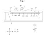
- FIG. 1 is a sectional view of the electronic device 100 viewed from the front.
- FIG. 2 is a plan view of the vibration device 10 viewed from below.
- FIG. 3 is a plan view of the support member 3 viewed from below.
- FIG. 4 is a plan view of the elastic connecting portion 33 viewed from below.
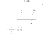
- FIG. 5 is a plan view of the actuator 4 viewed from below.
- FIG. 6 is a sectional view showing a situation in which the vibration device 1010 according to the comparative example falls and the vibration device 1010 according to the comparative example collides with the floor 6 in a state where the fixed part 31 is on the movable part 32.
- FIG. 7 is a cross-sectional view showing the directions of forces F1, F2, and F3 when the vibration device 10 collides with the floor 6 in a state where the fixed part 31 is on the movable part 32.
- FIG. 1 is a sectional view of the electronic device 100 viewed from the front.
- FIG. 2 is a plan view of the vibration device 10 viewed from below.
- FIG. 3 is a plan view of the support member 3 viewed from below.
- FIG. 4 is a plan view of the elastic connecting portion 33 viewed from below.
- FIG. 5 is a plan view of the actuator 4 viewed from below.
- FIG. 6 is a sectional view showing a situation in which the vibration device 1010 according to the comparative example falls and the vibration device 1010 according to the comparative example collides with the floor 6 in a state where the fixed part 31 is on the movable part 32.
- FIG. 7 is a cross-sectional view showing the directions of forces F1, F2, and F3 when the vibration device 10 collides with the floor 6 in a state where the fixed part 31 is on the movable part 32.
- the vibration device 10 is used, for example, in an electronic device 100 that provides tactile feedback to the user 200 by vibrating the vibrated member 2 when the user 200 presses the vibrated member 2. . Since the vibrated member 2 vibrates when the user 200 presses the vibrated member 2, the user 200 can feel that the vibrated member 2 has been pressed. In this way, the vibration device 10 is attached to the vibrated member 2.
- the housing 1 is a rectangular parallelepiped box. As shown in FIG. 1, the housing 1 is provided with an opening OP. More specifically, the opening OP has a rectangular shape when viewed in the vertical direction. As shown in FIG. 1, the opening OP passes through the upper surface of the housing 1 in the vertical direction.
- the vibrated member 2 has a plate shape, as shown in FIG. Therefore, the vibrated member 2 has an upper main surface US2 and a lower main surface LS2 that are arranged in the vertical direction.
- the upper main surface US2 is located above the lower main surface LS2.
- the upper main surface US2 and the lower main surface LS2 are parallel to each other.
- Each of the upper main surface US2 and the lower main surface LS2 has a rectangular shape with long sides extending in the left-right direction and short sides extending in the front-rear direction.
- the vertical position of the vibrated member 2 is equal to the vertical position of the upper surface of the housing 1, as shown in FIG. Further, the vibrated member 2 is located within the opening OP when viewed in the vertical direction. Thereby, the user 200 can press the upper main surface US2 of the vibrated member 2. Note that the vibrated member 2 is not in contact with the housing 1.
- the vibration device 10 includes a support member 3 and an actuator 4, as shown in FIG.
- the support member 3 includes a fixed part 31, a movable part 32, and an elastic connecting part 33, as shown in FIG.
- the movable part 32, the elastic connecting part 33, and the fixed part 31 are arranged in this order from left to right.
- the material of the support member 3 is metal such as SUS (Stainless Used Steel).
- the support member 3 is manufactured by punching a single SUS plate.
- the fixing part 31 is fixed to the housing 1, as shown in FIG. More specifically, the fixing part 31 has two screw holes 311, as shown in FIG.
- the fixing part 31 is fixed to the housing by inserting the bolts 5 from below each of the two screw holes 311 into each of the two screw holes 311 and into each of the two screw holes (not shown) of the housing 1. Fixed to body 1.
- the movable part 32 supports the vibrated member 2, as shown in FIG.
- the movable part 32 has an upper main surface US32 and a lower main surface LS32 that are arranged in the vertical direction.
- Upper main surface US32 is located above lower main surface LS32.
- the upper main surface US32 and the lower main surface LS32 are parallel to each other.
- each of the upper main surface US32 and the lower main surface LS32 has a rectangular shape with long sides extending in the left-right direction and short sides extending in the front-rear direction.
- the movable part 32 has a slit 321, as shown in FIG.
- the slit 321 passes through the movable portion 32 in the vertical direction.
- the slit 321 has a shape that extends in the front-rear direction when viewed in the up-down direction.
- the slit 321 has a rectangular shape with short sides extending in the left-right direction and long sides extending in the front-back direction.
- the slit 321 overlaps the elastic connecting portion 33 when viewed in the left-right direction.
- the elastic connecting portion 33 elastically connects the fixed portion 31 and the movable portion 32 in the left-right direction. More specifically, the movable part 32 is elastically connected to the fixed part 31 in the left-right direction via an elastic connecting part 33. Thereby, the movable part 32 can vibrate in any direction relative to the fixed part 31.
- the arbitrary direction is a left-right direction, a front-back direction, an up-down direction, or the like. Therefore, the elastic connecting portion 33 has a first elastic coefficient k1 in the left-right direction, and has a second elastic coefficient k2 in the up-down direction. Further, the second elastic coefficient k2 is smaller than the first elastic coefficient k1.
- the elastic connecting portion 33 has a first curved portion 331, a second curved portion 332, a third curved portion 333, a first connecting portion 334, and a second connecting portion 335.
- Each of the first curved section 331, the second curved section 332, and the third curved section 333 is elastically deformed.
- the first curved part 331, the second curved part 332, and the third curved part 333 are lined up in this order from left to right when viewed in the front-rear direction.
- the first curved portion 331 includes a shape that curves so as to protrude forward. Further, the left end portion of the first curved portion 331 has a shape extending in the front-rear direction. Therefore, the elastic connecting portion 33 includes a shape extending in the front-rear direction. Further, the right end portion of the first curved portion 331 has a shape extending from the front right direction to the rear left direction.
- the second curved portion 332 includes a shape that curves so as to protrude rearward. Further, the second curved portion 332 has an inner edge I332 and an outer edge O332.
- the inner edge I332 and the outer edge O332 are the inner edge of the arc and the outer edge of the arc, respectively. Therefore, the length of the outer edge O332 is longer than the length of the inner edge I332, and the radius of curvature of the outer edge O332 is equal to the radius of curvature of the inner edge I332.
- the left end portion of the second curved portion 332 has a shape extending from the front right direction to the rear left direction. Further, the right end portion of the second curved portion 332 has a shape extending from the front left direction to the rear right direction.
- the third curved portion 333 includes a shape that curves so as to protrude forward. Further, the left end portion of the third curved portion 333 has a shape extending from the front left direction to the rear right direction. Further, the right end portion of the third curved portion 333 has a shape extending in the front-rear direction.
- the shortest distance LRMIN13 in the left-right direction between the first curved part 331 and the third curved part 333 is shorter than the longest distance LRMAXO2 in the left-right direction of the outer edge O332 of the second curved part 332.
- the first connecting part 334 connects the movable part 32 and the first curved part 331, as shown in FIGS. 3 and 4. As shown in FIG. 4, the first connecting portion 334 has a shape extending in the first direction DIR1. Note that the first connecting portion 334 only needs to have a shape extending in the first direction DIR1.
- the first direction DIR1 forms a first angle ⁇ 1 counterclockwise with respect to the left-right direction when viewed in the up-down direction.
- the first angle ⁇ 1 is an angle greater than 0 degrees counterclockwise and less than 90 degrees counterclockwise. That is, the first direction DIR1 is different from the horizontal direction when viewed in the vertical direction.
- the first angle ⁇ 1 is an angle greater than 30 degrees counterclockwise and less than 90 degrees counterclockwise.
- the second connecting part 335 connects the fixed part 31 and the third curved part 333, as shown in FIGS. 3 and 4. As shown in FIG. 4, the second connecting portion 335 has a shape extending in the second direction DIR2. Note that the second connecting portion 335 only needs to have a shape extending in the second direction DIR2.
- the second direction DIR2 forms a second angle ⁇ 2 clockwise with respect to the left-right direction when viewed in the up-down direction.
- the second angle ⁇ 2 is an angle greater than 0 degrees clockwise and less than 90 degrees clockwise. That is, the second direction DIR2 is different from the left-right direction when viewed in the up-down direction.
- the second angle ⁇ 2 is an angle greater than 30 degrees clockwise and less than 90 degrees clockwise.
- the actuator 4 includes a piezoelectric film 41, a first electrode (not shown), and a second electrode (not shown).
- the actuator 4 has a film shape.
- the actuator 4 has a first main surface US4 and a second main surface LS4.
- the first main surface US4 is located on the second main surface LS4.
- the first main surface US4 and the second main surface LS4 are parallel to each other.
- the first main surface US4 is the upper surface of the first electrode.
- the second main surface LS4 is the lower surface of the second electrode.
- each of the first main surface US4 and the second main surface LS4 has a rectangular shape having a long side extending in the left-right direction and a short side extending in the front-rear direction when viewed in the vertical direction. .
- the piezoelectric film 41 is a piezoelectric body. That is, the actuator 4 includes a piezoelectric body. Moreover, the piezoelectric film 41 has an upper surface and a lower surface. The first electrode is provided on the top surface of the piezoelectric film 41 (not shown). The second electrode is provided on the lower surface of the piezoelectric film 41 (not shown). Each of the first electrode and the second electrode is a metal film formed by vapor deposition.
- the actuator 4 is attached to the fixed part 31 of the support member 3 and the movable part 32 of the support member 3, as shown in FIG. More specifically, the left end of the actuator 4 is attached to the movable part 32 via an adhesive (not shown) with the actuator 4 slightly stretched in the left and right direction, and the right end of the actuator 4 is attached to the movable part 32 via an adhesive (not shown).
- the actuator 4 is attached to the fixed part 31 via an adhesive (not shown) with the actuator 4 slightly stretched in the left and right direction.
- the actuator 4 expands and contracts in the left-right direction by applying an alternating current voltage to the actuator 4. More specifically, the piezoelectric film 41 expands and contracts in the left-right direction by applying an AC voltage between the first electrode and the second electrode. For example, the actuator 4 expands in the left-right direction when a positive voltage is applied to the actuator 4. On the other hand, the actuator 4 contracts in the left-right direction by applying a negative voltage to the actuator 4. Therefore, the actuator 4 vibrates in the left-right direction by applying an alternating current voltage to the actuator 4. Thereby, the actuator 4 vibrates the movable portion 32 of the vibrated member 2 and the support member 3 in the left-right direction.
- the AC voltage is a voltage whose polarity changes periodically.
- FIG. 6 a situation is assumed in which the vibration device 1010 according to the comparative example falls and the vibration device 1010 according to the comparative example collides with the floor 6 in a state where the fixed part 31 is on the movable part 32.
- the vertical direction in FIGS. 6 and 7 will be defined as the vertical vertical direction.
- the direction u in FIGS. 6 and 7 is defined as a vertically upward direction
- the direction d in FIGS. 6 and 7 is defined as a vertically downward direction.
- the left-right direction and the front-back direction in FIGS. 6 and 7 are defined as a horizontal left-right direction and a horizontal front-back direction, respectively.
- FIGS. 6 and 7 is defined as the horizontal left direction
- the direction r in FIGS. 6 and 7 is defined as the horizontal right direction
- the direction f in FIGS. 6 and 7 is defined as the horizontal front direction
- the direction b in FIGS. 6 and 7 is defined as the horizontal rear direction.
- the vertical up-down direction coincides with the left-right direction.
- the horizontal left-right direction coincides with the front-back direction.
- the horizontal front-back direction coincides with the up-down direction.
- the vertical up-down direction, the horizontal left-right direction, and the horizontal front-back direction are orthogonal to each other.
- the vibration device 1010 according to the comparative example differs from the vibration device 10 in that the second elastic coefficient k2 is greater than or equal to the first elastic coefficient k1.
- the shape of the vibration device 1010 according to the comparative example is an example.
- the vibration device 1010 according to the comparative example collides with the floor 6, the vibration device 1010 according to the comparative example receives the impact force F from the floor 6, and the elastic connecting portion 33 also receives the impact force F.
- the second elastic coefficient k2 is greater than or equal to the first elastic coefficient k1.
- the elastic connecting portion 33 is more easily deformed in the left-right direction than in the up-down direction. Therefore, the elastic connecting portion 33 contracts in the vertical up-down direction (left-right direction in FIGS. 1 to 5). This causes slack in the actuator 4. Therefore, the vibration of the actuator 4 is less likely to be transmitted to the vibrated member 2.
- the second elastic coefficient k2 is smaller than the first elastic coefficient k1.
- the elastic connecting portion 33 is more easily deformed in the up-down direction than in the left-right direction. Therefore, when the vibration device 10 collides with the floor 6, the elastic connecting portion 33 moves not only in the vertical up-down direction (the left-right direction in FIGS. 1 to 5), but also in the horizontal front-back direction (the up-down direction in FIGS. 1 to 5). Can be elastically deformed. Therefore, according to the vibrating device 10, the elastic range of the elastic connecting portion 33 is expanded. Therefore, in order to plastically deform the elastic connecting portion 33, a larger force is required. Therefore, according to the vibrating device 10, the elastic connecting portion 33 is less likely to be plastically deformed. As a result, according to the vibrating device 10, the drop resistance of the vibrating device can be improved.
- the elastic connecting portion 33 includes a first curved portion 331 that is elastically deformed, a second curved portion 332 that is elastically deformed, and a third curved portion 333 that is elastically deformed.
- the first curved part 331, the second curved part 332, and the third curved part 333 are lined up in this order from left to right when viewed in the front-rear direction.
- the first curved portion 331 and the third curved portion 333 include a shape that curves so as to protrude in the front direction
- the second curved portion 332 includes a shape that curves so as to protrude in the rear direction.
- the second curved portion 332 can be elastically deformed in the horizontal front-rear direction (up-down direction in FIGS. 1 to 5). More specifically, both ends of the second curved portion 332 are not fixed. Thereby, the outer edge O332 of the second curved part 332 and the inner edge I332 of the second curved part 332 are easily deformed in the vertical direction. Therefore, the elastic connecting portion 33 is easily elastically deformed and torsionally deformed in the horizontal front-rear direction (vertical direction in FIGS. 1 to 5), and the elastic range of the elastic connecting portion 33 is expanded. Therefore, in order to plastically deform the elastic connecting portion 33, a larger force is required. Therefore, according to the vibrating device 10, the elastic connecting portion 33 is less likely to be plastically deformed. As a result, according to the vibrating device 10, the drop resistance of the vibrating device can be further improved.
- the drop resistance of the vibrating device can be further improved. More specifically, the shortest distance LRMIN13 in the left-right direction between the first curved part 331 and the third curved part 333 is shorter than the longest distance LRMAXO2 in the left-right direction of the outer edge O332 of the second curved part 332. As a result, each of the right end portion of the first curved portion 331 and the left end portion of the second curved portion 332 has a shape extending from the front right direction to the rear left direction. Further, each of the right end portion of the second curved portion 332 and the left end portion of the third curved portion 333 has a shape extending from the front left direction to the rear right direction.
- the elastic connecting portion 33 is less likely to be plastically deformed.
- the drop resistance of the vibrating device can be further improved.
- the drop resistance of the vibrating device can be further improved.
- the first connecting portion 334 includes a shape extending in the first direction DIR1.
- the first direction DIR1 forms an angle greater than 0 degrees counterclockwise and less than 90 degrees counterclockwise with respect to the left and right direction when viewed in the vertical direction.
- a force F2 is applied to the first connecting portion 334, as shown in FIG.
- the force F2 causes twisting between the first connecting portion 334 and the first curved portion 331.
- the first curved portion 331 is twisted relative to the first curved portion 331, and as a result, the second curved portion 332 is easily twisted and deformed in the horizontal front-rear direction (vertical direction in FIGS. 1 to 5). Therefore, the elastic connecting portion 33 is easily elastically deformed and torsionally deformed in the horizontal front-rear direction (vertical direction in FIGS. 1 to 5), and the elastic range of the elastic connecting portion 33 is expanded. Therefore, in order to plastically deform the elastic connecting portion 33, a larger force is required. Therefore, according to the vibrating device 10, the elastic connecting portion 33 is less likely to be plastically deformed. As a result, according to the vibrating device 10, the drop resistance of the vibrating device can be further improved.
- the second connecting portion 335 includes a shape extending in the second direction DIR2.
- the second direction DIR2 forms an angle greater than 0 degrees clockwise and less than 90 degrees clockwise with respect to the left and right direction when viewed in the vertical direction.
- the third curved portion 333 is twisted relative to the second connecting portion 335, and as a result, the second curved portion 332 is easily twisted and deformed in the horizontal front-rear direction (vertical direction in FIGS. 1 to 5). Therefore, the elastic connecting portion 33 is easily elastically deformed and torsionally deformed in the horizontal front-rear direction (vertical direction in FIGS. 1 to 5), and the elastic range of the elastic connecting portion 33 is expanded. Therefore, in order to plastically deform the elastic connecting portion 33, a larger force is required. Therefore, according to the vibrating device 10, the elastic connecting portion 33 is less likely to be plastically deformed. As a result, according to the vibrating device 10, the drop resistance of the vibrating device can be further improved.
- the drop resistance of the vibrating device can be further improved.
- the movable part 32 has a slit 321 that passes through the movable part 32 in the vertical direction.
- the slit 321 has a shape that extends in the front-rear direction when viewed in the up-down direction.
- the slit 321 overlaps with the elastic connecting portion 33 when viewed in the left-right direction.
- the impact force F that the vibration device 10 receives from the floor 6 is dispersed into a force that contributes to the deformation of the elastic connecting portion 33 and a force that contributes to the deformation of the movable portion 32. Therefore, in order to plastically deform the elastic connecting portion 33, a larger force is required. Therefore, according to the vibrating device 10, the elastic connecting portion 33 is less likely to be plastically deformed. As a result, according to the vibrating device 10, the drop resistance of the vibrating device can be further improved.
- the vibration device according to the present invention is not limited to the vibration device 10, and can be modified within the scope of the gist.
- the vibrating device 10 and the vibrated member 2 may be modularized to form the vibrating device 20.
- the vibration device 10 and the housing 1 may be modularized to form the electronic device 30.
- the vibration device 10, the housing 1, and the vibrated member 2 may be modularized to form the electronic device 100.
- the use of the electronic device 100 is not limited to providing tactile feedback to the user 200.
- actuator 4 may be attached to the fixed portion 31 of the support member 3 and the vibrated member 2.
- first direction DIR1 forms a first angle ⁇ 1 that is larger than 45 degrees counterclockwise and smaller than 90 degrees counterclockwise with respect to the left and right direction when viewed in the vertical direction. You may.
- second direction DIR2 forms a second angle ⁇ 2 that is larger than 45 degrees clockwise and smaller than 90 degrees clockwise with respect to the left and right direction when viewed in the vertical direction. Good too. Also in this case, the drop resistance of the vibration device can be further improved.
- first direction DIR1 forms a first angle ⁇ 1 that is larger than 60 degrees counterclockwise and smaller than 90 degrees counterclockwise with respect to the left and right direction when viewed in the vertical direction. You may.
- second direction DIR2 forms a second angle ⁇ 2 that is larger than 60 degrees clockwise and smaller than 90 degrees clockwise with respect to the left and right direction when viewed in the vertical direction. Good too. Also in this case, the drop resistance of the vibration device can be further improved.
- vibration device 10 is not limited to being used in the electronic device 100.
- the vibrated member 2 is not limited to the user 200, and may be pressed by an operating member.
- housing 1 is not limited to being a rectangular parallelepiped box.
- the opening OP does not have to have a rectangular shape when viewed in the vertical direction.
- the vibrated member 2 does not need to have a plate shape. Furthermore, the vibrated member 2 does not need to have the upper main surface US2 and the lower main surface LS2 that are arranged in the vertical direction. Moreover, the upper main surface US2 and the lower main surface LS2 do not have to be parallel to each other.
- each of the upper main surface US2 and the lower main surface LS2 does not have to have a rectangular shape having a long side extending in the left-right direction and a short side extending in the front-back direction.
- the vertical position of the vibrated member 2 does not have to be equal to the vertical position of the upper surface of the housing 1.
- the vibrated member 2 does not need to be located within the opening OP when viewed in the vertical direction.
- vibrated member 2 may be in contact with the housing 1.
- the material of the support member 3 does not have to be metal such as SUS (Stainless Used Steel).
- the support member 3 does not have to be produced by punching a single SUS plate.
- the fixing part 31 may be fixed to the housing 1 with an adhesive. Therefore, the fixing part 31 does not need to have the screw hole 311. Further, the housing 1 does not need to have a screw hole. Further, the bolt 5 is not an essential component.
- the fixing part 31 has screw holes 311, it is preferable that there are two or more screw holes 311.
- the fixing part 31 can easily rotate around the screw hole 311 when viewed in the vertical direction due to the vibration of the actuator 4.
- the actuator 4 When the fixed part 31 rotates around the screw hole 311 when viewed in the vertical direction due to the vibration of the actuator 4, the actuator 4 generates vibration energy that causes the vibrated member 2 and the movable part 32 of the support member 3 to vibrate in the left-right direction. A part of it is consumed by the rotation of the fixed part 31. This reduces the efficiency with which the actuator 4 vibrates the movable portion 32 of the vibrated member 2 and the support member 3 in the left-right direction.
- the fixing part 31 has two or more screw holes 311, it is possible to suppress part of the vibration energy from being consumed in rotating the fixing part 31. Since the fixed part 31 has two or more screw holes 311, the actuator 4 can efficiently vibrate the movable part 32 of the vibrated member 2 and the support member 3 in the left-right direction.
- each of the upper main surface US32 and the lower main surface LS32 does not have to have a rectangular shape having a long side extending in the left-right direction and a short side extending in the front-back direction.
- the slit 321 does not have to have a rectangular shape having short sides extending in the left-right direction and long sides extending in the front-back direction.
- the actuator 4 does not need to include a piezoelectric body.
- the actuator 4 may be, for example, an LRA (Linear Resonant Actuator).
- radius of curvature of the outer edge O332 does not have to be equal to the radius of curvature of the inner edge I332.
- drop resistance means resistance to plastic deformation.
- the present invention has the following structure.
- a vibration device attached to a vibrated member is a support member; an actuator that vibrates the vibrated member in the left-right direction; It is equipped with
- the support member is a fixed part; a movable part having an upper principal surface and a lower principal surface aligned in the vertical direction; an elastic connecting part that elastically connects the fixed part and the movable part in the left-right direction; including;
- the movable part supports the vibrated member,
- the actuator is attached to the fixed part and the movable part or the vibrated member,
- the elastic connecting portion has a first elastic modulus in the left-right direction and a second elastic modulus in the up-down direction, the second elastic modulus is smaller than the first elastic modulus, Vibration device.
- the elastic connecting portion has a first curved portion that is elastically deformed, a second curved portion that is elastically deformed, and a third curved portion that is elastically deformed,
- the first curved part, the second curved part, and the third curved part are arranged in this order from left to right when viewed in the front-rear direction,
- the first curved portion and the third curved portion include a shape that curves so as to protrude forward
- the second curved portion includes a shape that curves so as to protrude in the rear direction.
- the elastic connecting portion includes a first connecting portion connecting the movable portion and the first curved portion, Furthermore, it has The first connecting portion includes a shape extending in a first direction, The first direction forms an angle greater than 0 degrees counterclockwise and less than 90 degrees counterclockwise with respect to the left and right direction when viewed in the vertical direction.
- the first direction forms an angle greater than 30 degrees counterclockwise and less than 90 degrees counterclockwise with respect to the left and right direction when viewed in the vertical direction.
- the first direction forms an angle greater than 45 degrees counterclockwise and less than 90 degrees counterclockwise with respect to the left and right direction when viewed in the vertical direction.
- the first direction forms an angle greater than 60 degrees counterclockwise and less than 90 degrees counterclockwise with respect to the left and right direction when viewed in the vertical direction.
- the elastic connecting portion includes a second connecting portion connecting the fixed portion and the third curved portion, Furthermore, it has The second connecting portion includes a shape extending in a second direction, The second direction forms an angle greater than 0 degrees clockwise and less than 90 degrees counterclockwise with respect to the left and right direction when viewed in the vertical direction.
- the vibration device according to any one of (2) to (7).
- the second direction forms an angle greater than 30 degrees clockwise and less than 90 degrees counterclockwise with respect to the left and right direction when viewed in the vertical direction.
- the second direction forms an angle greater than 45 degrees clockwise and less than 90 degrees counterclockwise with respect to the left and right direction when viewed in the vertical direction.
- the second direction forms an angle greater than 60 degrees clockwise and less than 90 degrees counterclockwise with respect to the left and right direction when viewed in the vertical direction.
- the movable part has a slit that passes through the movable part in the vertical direction,
- the slit has a shape extending in the front-rear direction when viewed in the up-down direction, The slit overlaps the elastic connecting portion when viewed in the left-right direction,
- the vibration device according to any one of (1) to (11).
- the elastic connecting portion includes a shape extending in the front-back direction.
- the vibration device according to any one of (1) to (12).
- the actuator includes a piezoelectric film.
- the vibration device according to any one of (1) to (13).
Landscapes
- Engineering & Computer Science (AREA)
- General Engineering & Computer Science (AREA)
- Theoretical Computer Science (AREA)
- Human Computer Interaction (AREA)
- Physics & Mathematics (AREA)
- General Physics & Mathematics (AREA)
- Mechanical Engineering (AREA)
- Apparatuses For Generation Of Mechanical Vibrations (AREA)
Abstract
被振動部材に取り付けられる振動装置であって、振動装置は、支持部材と、被振動部材を左右方向に振動させるアクチュエータと、を備えており、支持部材は、固定部と、上下方向に並ぶ上主面及び下主面を有する可動部と、固定部と可動部とを左右方向に弾性的に連結する弾性連結部と、を含み、可動部は、被振動部材を支持し、アクチュエータは、固定部と、可動部又は被振動部材と、に取り付けられ、弾性連結部は、左右方向において、第1弾性係数を有し、かつ、上下方向において、第2弾性係数を有し、第2弾性係数は、第1弾性係数より小さい。
Description
本発明は、振動装置及び振動装置を備える電子機器に関する。
従来の振動装置に関する発明としては、例えば、特許文献1に記載の振動構造が知られている。特許文献1に記載の振動構造は、フィルムと、枠状部材と、振動部と、支持部と、第1接続部材と、第2接続部材と、を備えている。枠状部材は、枠状部材の法線方向に視て、開口が設けられた枠形状を有している。振動部は、枠状部材の法線方向に視て、開口内に位置している。支持部は、枠状部材と振動部とを連結している。支持部が弾性変形することにより、振動部は、枠状部材に対して変位することができる。
また、フィルムは、第1端部と第2端部とを有する長方形状を有している。第1接続部材は、フィルムの第1端部と振動部とを固定している。第2接続部材は、フィルムの第2端部と枠状部材とを固定している。
以上のような構造を有する振動構造では、フィルムに電圧が印加されることにより、第1端部と第2端部との距離が変化するようにフィルムが変形する。これにより、振動部は、枠状部材に対して振動する。
ところで、特許文献1に記載の振動構造において、振動構造の落下耐性を向上させたいという要望がある。
そこで、本発明の目的は、振動装置の落下耐性を向上することができる振動装置及び電子機器を提供することである。
本発明の一形態に係る振動装置は、
被振動部材に取り付けられる振動装置であって、
前記振動装置は、
支持部材と、
前記被振動部材を左右方向に振動させるアクチュエータと、
を備えており、
前記支持部材は、
固定部と、
上下方向に並ぶ上主面及び下主面を有する可動部と、
前記固定部と前記可動部とを前記左右方向に弾性的に連結する弾性連結部と、
を含み、
前記可動部は、前記被振動部材を支持し、
前記アクチュエータは、前記固定部と、前記可動部又は前記被振動部材と、に取り付けられ、
前記弾性連結部は、前記左右方向において、第1弾性係数を有し、かつ、前記上下方向において、第2弾性係数を有し、
前記第2弾性係数は、前記第1弾性係数より小さい。
被振動部材に取り付けられる振動装置であって、
前記振動装置は、
支持部材と、
前記被振動部材を左右方向に振動させるアクチュエータと、
を備えており、
前記支持部材は、
固定部と、
上下方向に並ぶ上主面及び下主面を有する可動部と、
前記固定部と前記可動部とを前記左右方向に弾性的に連結する弾性連結部と、
を含み、
前記可動部は、前記被振動部材を支持し、
前記アクチュエータは、前記固定部と、前記可動部又は前記被振動部材と、に取り付けられ、
前記弾性連結部は、前記左右方向において、第1弾性係数を有し、かつ、前記上下方向において、第2弾性係数を有し、
前記第2弾性係数は、前記第1弾性係数より小さい。
本明細書において、方向を以下のように定義する。図1乃至図5において、上下方向は、可動部32の上主面US32の法線が延びる方向である。図1乃至図5において、左右方向は、アクチュエータ4が被振動部材2を振動させる方向である。図1乃至図5において、前後方向は、第1湾曲部331、第2湾曲部332又は第3湾曲部333が突出している方向である。上下方向、左右方向及び前後方向は、互いに直交している。なお、本明細書における方向の定義は、一例である。従って、振動装置10の実使用時における方向と本明細書における方向とが一致している必要はない。
以下では、X,Yは、電子機器100の部品又は部材である。本明細書において、特に断りのない場合には、Xの各部について以下のように定義する。Xの上部とは、Xの上半分を意味する。Xの上端とは、Xの上方向の端を意味する。Xの上端部とは、Xの上端及びその近傍を意味する。この定義は、上方向以外の方向にも適用される。
また、「Xは、Yの上に位置している。」とは、XがYの真上に位置していることを意味する。従って、上下方向に視て、Xは、Yと重なっている。「Xは、Yより上に位置している。」とは、XがYの真上に位置していること、及び、XがYの斜め上に位置していることを意味する。従って、上下方向に視て、Xは、Yと重なっていてもよいし、Yと重なっていなくてもよい。この定義は、上方向以外の方向にも適用される。
本発明に係る振動装置によれば、振動装置の落下耐性を向上することができる。
[実施形態]
以下に、本発明の一実施形態に係る振動装置10の構成について図面を参照しながら説明する。図1は、電子機器100を前方向に視た断面図である。図2は、振動装置10を下方向に視た平面図である。図3は、支持部材3を下方向に視た平面図である。図4は、弾性連結部33を下方向に視た平面図である。図5は、アクチュエータ4を下方向に視た平面図である。図6は、固定部31が可動部32の上にある状態において、比較例に係る振動装置1010が落下し、比較例に係る振動装置1010が床6に衝突する状況を示した断面図である。図7は、固定部31が可動部32の上にある状態において、振動装置10が床6に衝突したときの力F1,F2,F3の方向を示した断面図である。
以下に、本発明の一実施形態に係る振動装置10の構成について図面を参照しながら説明する。図1は、電子機器100を前方向に視た断面図である。図2は、振動装置10を下方向に視た平面図である。図3は、支持部材3を下方向に視た平面図である。図4は、弾性連結部33を下方向に視た平面図である。図5は、アクチュエータ4を下方向に視た平面図である。図6は、固定部31が可動部32の上にある状態において、比較例に係る振動装置1010が落下し、比較例に係る振動装置1010が床6に衝突する状況を示した断面図である。図7は、固定部31が可動部32の上にある状態において、振動装置10が床6に衝突したときの力F1,F2,F3の方向を示した断面図である。
振動装置10は、図1に示すように、一例として、ユーザ200が被振動部材2を押したときに被振動部材2を振動させることで、ユーザ200に触覚フィードバックを与える電子機器100に用いられる。ユーザ200が被振動部材2を押したときに被振動部材2が振動するため、ユーザ200は、被振動部材2を押したと感じることができる。このように、振動装置10は、被振動部材2に取り付けられる。
筐体1は、直方体形状の箱である。筐体1には、図1に示すように、開口OPが設けられている。より詳細には、開口OPは、上下方向に視て、矩形状を有している。開口OPは、図1に示すように、筐体1の上面を上下方向に貫通している。
被振動部材2は、図1に示すように、板形状を有している。従って、被振動部材2は、上下方向に並ぶ上主面US2及び下主面LS2を有している。上主面US2は、下主面LS2の上に位置している。上主面US2及び下主面LS2は、互いに平行である。上主面US2及び下主面LS2のそれぞれは、左右方向に延びる長辺及び前後方向に延びる短辺を有する矩形状を有している。
被振動部材2の上下方向の位置は、図1に示すように、筐体1の上面の上下方向の位置と等しい。また、被振動部材2は、上下方向に視て、開口OP内に位置している。これにより、ユーザ200は、被振動部材2の上主面US2を押すことができる。なお、被振動部材2は、筐体1に接触していない。
振動装置10は、図2に示すように、支持部材3及びアクチュエータ4を備えている。支持部材3は、図3に示すように、固定部31、可動部32及び弾性連結部33を含んでいる。可動部32、弾性連結部33及び固定部31は、左から右へとこの順に並んでいる。支持部材3の材料は、SUS(Stainless Used Steel)等の金属である。支持部材3は、1枚のSUS板を打抜き加工することにより作製される。
固定部31は、図1に示すように、筐体1に固定される。より詳細には、固定部31は、図3に示すように、2つのネジ穴311を有する。固定部31は、2つのネジ穴311のそれぞれの下から、2つのネジ穴311のそれぞれ及び筐体1の2つのネジ穴(図示せず)のそれぞれにボルト5が挿入されることにより、筐体1に固定される。
可動部32は、図1に示すように、被振動部材2を支持する。可動部32は、上下方向に並ぶ上主面US32及び下主面LS32を有している。上主面US32は、下主面LS32の上に位置している。上主面US32及び下主面LS32は、互いに平行である。上主面US32及び下主面LS32のそれぞれは、図3に示すように、左右方向に延びる長辺及び前後方向に延びる短辺を有する矩形状を有している。
可動部32は、図3に示すように、スリット321を有している。スリット321は、可動部32を上下方向に貫通している。スリット321は、上下方向に視て、前後方向に延びる形状を有している。スリット321は、左右方向に延びる短辺及び前後方向に延びる長辺を有する矩形状を有している。スリット321は、左右方向に視て、弾性連結部33と重なっている。
弾性連結部33は、図3に示すように、固定部31と可動部32とを左右方向に弾性的に連結している。より詳細には、可動部32は、弾性連結部33を介して、固定部31に左右方向に弾性的に連結されている。これにより、可動部32は、固定部31に対して任意の方向に振動することができる。任意の方向とは、左右方向、前後方向又は上下方向等である。従って、弾性連結部33は、左右方向において、第1弾性係数k1を有し、かつ、上下方向において、第2弾性係数k2を有する。また、第2弾性係数k2は、第1弾性係数k1より小さい。
弾性連結部33は、図4に示すように、第1湾曲部331、第2湾曲部332、第3湾曲部333、第1連結部334及び第2連結部335を有している。第1湾曲部331、第2湾曲部332及び第3湾曲部333のそれぞれは、弾性変形する。また、第1湾曲部331、第2湾曲部332及び第3湾曲部333は、前後方向に視て、左から右へとこの順に並んでいる。
第1湾曲部331は、図4に示すように、前方向に突出するように湾曲する形状を含んでいる。また、第1湾曲部331の左端部は、前後方向に延びる形状を有している。従って、弾性連結部33は、前後方向に延びる形状を含んでいる。また、第1湾曲部331の右端部は、右前方向から左後方向に延びる形状を有している。
第2湾曲部332は、図4に示すように、後方向に突出するように湾曲する形状を含んでいる。また、第2湾曲部332は、内縁I332及び外縁O332を有する。内縁I332及び外縁O332のそれぞれは、弧の内縁及び弧の外縁である。従って、外縁O332の長さは、内縁I332の長さよりも長く、かつ、外縁O332の曲率半径は、内縁I332の曲率半径と等しい。また、第2湾曲部332の左端部は、右前方向から左後方向に延びる形状を有している。また、第2湾曲部332の右端部は、左前方向から右後方向に延びる形状を有している。
第3湾曲部333は、図4に示すように、前方向に突出するように湾曲する形状を含んでいる。また、第3湾曲部333の左端部は、左前方向から右後方向に延びる形状を有している。また、第3湾曲部333の右端部は、前後方向に延びる形状を有している。
第1湾曲部331と第3湾曲部333との間の左右方向の最短距離LRMIN13は、図4に示すように、第2湾曲部332の外縁O332の左右方向の最長距離LRMAXO2より短い。
第1連結部334は、図3及び図4に示すように、可動部32と第1湾曲部331とを連結する。第1連結部334は、図4に示すように、第1方向DIR1に延びる形状を有している。なお、第1連結部334は、第1方向DIR1に延びる形状を含んでいればよい。
第1方向DIR1は、図4に示すように、上下方向に視て、左右方向に対して、反時計回りに第1角度θ1を形成する。第1角度θ1は、反時計回りに0度より大きい角度であって、反時計回りに90度より小さい角度である。すなわち、第1方向DIR1は、上下方向に視て、左右方向と異なる。本実施形態では、第1角度θ1は、反時計回りに30度より大きい角度であって、反時計回りに90度より小さい角度である。
第2連結部335は、図3及び図4に示すように、固定部31と第3湾曲部333とを連結する。第2連結部335は、図4に示すように、第2方向DIR2に延びる形状を有している。なお、第2連結部335は、第2方向DIR2に延びる形状を含んでいればよい。
第2方向DIR2は、図4に示すように、上下方向に視て、左右方向に対して、時計回りに第2角度θ2を形成する。第2角度θ2は、時計回りに0度より大きい角度であって、時計回りに90度より小さい角度である。すなわち、第2方向DIR2は、上下方向に視て、左右方向と異なる。本実施形態では、第2角度θ2は、時計回りに30度より大きい角度であって、時計回りに90度より小さい角度である。
アクチュエータ4は、図5に示すように、圧電フィルム41、第1電極(図示せず)及び第2電極(図示せず)を含んでいる。アクチュエータ4は、フィルム形状を有している。
アクチュエータ4は、図1に示すように、第1主面US4及び第2主面LS4を有している。第1主面US4は、第2主面LS4の上に位置している。第1主面US4及び第2主面LS4は、互いに平行である。第1主面US4は、第1電極の上面である。第2主面LS4は、第2電極の下面である。第1主面US4及び第2主面LS4のそれぞれは、図5に示すように、上下方向に視て、左右方向に延びる長辺及び前後方向に延びる短辺を有する矩形状を有している。
圧電フィルム41は、圧電体である。すなわち、アクチュエータ4は、圧電体を含んでいる。また、圧電フィルム41は、上面及び下面を有している。第1電極は、圧電フィルム41の上面に設けられている(図示せず)。第2電極は、圧電フィルム41の下面に設けられている(図示せず)。第1電極及び第2電極のそれぞれは、蒸着による金属皮膜である。
アクチュエータ4は、図2に示すように、支持部材3の固定部31と、支持部材3の可動部32と、に取り付けられる。より詳細には、アクチュエータ4の左端部は、アクチュエータ4が僅かに左右方向に伸ばされた状態で、接着材(図示せず)を介して、可動部32に取り付けられ、かつ、アクチュエータ4の右端部は、アクチュエータ4が僅かに左右方向に伸ばされた状態で、接着材(図示せず)を介して、固定部31に取り付けられる。
アクチュエータ4は、アクチュエータ4に交流電圧が印加されることにより、左右方向に伸縮する。より詳細には、圧電フィルム41は、第1電極と第2電極との間に交流電圧が印加されることにより、左右方向に伸縮する。例えば、アクチュエータ4は、アクチュエータ4に正の電圧が印加されることにより、左右方向に伸張する。一方、アクチュエータ4は、アクチュエータ4に負の電圧が印加されることにより、左右方向に収縮する。従って、アクチュエータ4は、アクチュエータ4に交流電圧が印加されることにより、左右方向に振動する。これにより、アクチュエータ4は、被振動部材2及び支持部材3の可動部32を左右方向に振動させる。なお、交流電圧は、周期的に電圧の正負が変化する電圧である。
[効果]
図6に示すように、固定部31が可動部32の上にある状態において、比較例に係る振動装置1010が落下し、比較例に係る振動装置1010が床6に衝突する状況を仮定する。以下では、図6及び図7の上下方向を鉛直上下方向と定義する。図6及び図7における方向uを鉛直上方向と定義し、図6及び図7における方向dを鉛直下方向と定義する。また、図6及び図7の左右方向及び前後方向のそれぞれを水平左右方向及び水平前後方向と定義する。図6及び図7における方向lを水平左方向と定義し、図6及び図7における方向rを水平右方向と定義する。また、図6及び図7における方向fを水平前方向と定義し、図6及び図7における方向bを水平後方向と定義する。鉛直上下方向は、左右方向と一致する。水平左右方向は、前後方向と一致する。水平前後方向は、上下方向と一致する。鉛直上下方向、水平左右方向及び水平前後方向は、互いに直交している。
図6に示すように、固定部31が可動部32の上にある状態において、比較例に係る振動装置1010が落下し、比較例に係る振動装置1010が床6に衝突する状況を仮定する。以下では、図6及び図7の上下方向を鉛直上下方向と定義する。図6及び図7における方向uを鉛直上方向と定義し、図6及び図7における方向dを鉛直下方向と定義する。また、図6及び図7の左右方向及び前後方向のそれぞれを水平左右方向及び水平前後方向と定義する。図6及び図7における方向lを水平左方向と定義し、図6及び図7における方向rを水平右方向と定義する。また、図6及び図7における方向fを水平前方向と定義し、図6及び図7における方向bを水平後方向と定義する。鉛直上下方向は、左右方向と一致する。水平左右方向は、前後方向と一致する。水平前後方向は、上下方向と一致する。鉛直上下方向、水平左右方向及び水平前後方向は、互いに直交している。
比較例に係る振動装置1010は、第2弾性係数k2が第1弾性係数k1以上である点において、振動装置10と相違する。なお、比較例に係る振動装置1010の形状は、一例である。比較例に係る振動装置1010が床6に衝突すると、比較例に係る振動装置1010が床6から衝撃力Fを受け、弾性連結部33も衝撃力Fを受ける。第2弾性係数k2は、第1弾性係数k1以上である。これにより、弾性連結部33は、上下方向よりも左右方向に変形しやすい。そのため、弾性連結部33は、鉛直上下方向(図1乃至図5における左右方向)に収縮する。これにより、アクチュエータ4に弛みが生じる。従って、アクチュエータ4の振動が、被振動部材2に伝達されにくくなる。
そこで、振動装置10では、第2弾性係数k2は、第1弾性係数k1より小さい。これにより、弾性連結部33は、左右方向よりも上下方向に変形しやすい。そのため、振動装置10が床6に衝突したとき、弾性連結部33は、鉛直上下方向(図1乃至図5における左右方向)に加えて、水平前後方向(図1乃至図5における上下方向)に弾性変形することができる。従って、振動装置10によれば、弾性連結部33の弾性域が拡大される。そのため、弾性連結部33を塑性変形させるためには、より大きい力が必要となる。従って、振動装置10によれば、弾性連結部33が塑性変形しにくくなる。その結果、振動装置10によれば、振動装置の落下耐性を向上することができる。
振動装置10によれば、振動装置の落下耐性をより向上することができる。より詳細には、弾性連結部33は、弾性変形する第1湾曲部331、弾性変形する第2湾曲部332及び弾性変形する第3湾曲部333を有している。また、第1湾曲部331、第2湾曲部332及び第3湾曲部333は、前後方向に視て、左から右へとこの順に並んでいる。第1湾曲部331及び第3湾曲部333は、前方向に突出するように湾曲する形状を含み、第2湾曲部332は、後方向に突出するように湾曲する形状を含んでいる。これにより、振動装置10が床6に衝突したとき、第2湾曲部332は、水平前後方向(図1乃至図5における上下方向)に弾性変形することができる。より詳細には、第2湾曲部332の両端は、いずれも固定されていない。これにより、第2湾曲部332の外縁O332及び第2湾曲部332の内縁I332は、上下方向に変形しやすくなる。従って、弾性連結部33は、水平前後方向(図1乃至図5における上下方向)に弾性変形及び捻れ変形しやすくなり、弾性連結部33の弾性域が拡大される。そのため、弾性連結部33を塑性変形させるためには、より大きい力が必要となる。従って、振動装置10によれば、弾性連結部33が塑性変形しにくくなる。その結果、振動装置10によれば、振動装置の落下耐性をより向上することができる。
振動装置10によれば、振動装置の落下耐性をより向上することができる。より詳細には、第1湾曲部331と第3湾曲部333との間の左右方向の最短距離LRMIN13は、第2湾曲部332の外縁O332の左右方向の最長距離LRMAXO2より短い。これにより、第1湾曲部331の右端部及び第2湾曲部332の左端部のそれぞれは、右前方向から左後方向に延びる形状を有している。また、第2湾曲部332の右端部及び第3湾曲部333の左端部のそれぞれは、左前方向から右後方向に延びる形状を有している。振動装置10が床6に衝突したとき、第1湾曲部331の右端部及び第2湾曲部332の左端部、及び、第2湾曲部332の右端部及び第3湾曲部333の左端部のそれぞれには、図7に示すように、力F1が働く。これにより、第1湾曲部331と第3湾曲部333との間の左右方向の最短距離LRMIN13が短くなり、第2湾曲部332は、水平前後方向(図1乃至図5における上下方向)に反りやすくなる。従って、第2湾曲部332は、水平前後方向(図1乃至図5における上下方向)に弾性変形しやすくなる。そのため、弾性連結部33を塑性変形させるためには、より大きい力が必要となる。従って、振動装置10によれば、弾性連結部33が塑性変形しにくくなる。その結果、振動装置10によれば、振動装置の落下耐性をより向上することができる。
振動装置10によれば、振動装置の落下耐性をより向上することができる。より詳細には、第1連結部334は、第1方向DIR1に延びる形状を含んでいる。第1方向DIR1は、上下方向に視て、左右方向に対して、反時計回りに0度より大きい角度であって、反時計回りに90度より小さい角度を形成している。これにより、振動装置10が床6に衝突したとき、第1連結部334には、図7に示すように、力F2が働く。力F2により、第1連結部334と第1湾曲部331との間に捻れが生じる。これにより、第1湾曲部331が第1湾曲部331に対して捻れ、その結果、第2湾曲部332が水平前後方向(図1乃至図5における上下方向)に捻れ変形しやすくなる。従って、弾性連結部33は、水平前後方向(図1乃至図5における上下方向)に弾性変形及び捻れ変形しやすくなり、弾性連結部33の弾性域が拡大される。そのため、弾性連結部33を塑性変形させるためには、より大きい力が必要となる。従って、振動装置10によれば、弾性連結部33が塑性変形しにくくなる。その結果、振動装置10によれば、振動装置の落下耐性をより向上することができる。
振動装置10によれば、振動装置の落下耐性をより向上することができる。より詳細には、第2連結部335は、第2方向DIR2に延びる形状を含んでいる。第2方向DIR2は、上下方向に視て、左右方向に対して、時計回りに0度より大きい角度であって、時計回りに90度より小さい角度を形成する。これにより、振動装置10が床6に衝突したとき、第2連結部335には、図7に示すように、力F3が働く。力F3により、第2連結部335と第3湾曲部333との間に捻れが生じる。これにより、第3湾曲部333が第2連結部335に対して捻れ、その結果、第2湾曲部332が水平前後方向(図1乃至図5における上下方向)に捻れ変形しやすくなる。従って、弾性連結部33は、水平前後方向(図1乃至図5における上下方向)に弾性変形及び捻れ変形しやすくなり、弾性連結部33の弾性域が拡大される。そのため、弾性連結部33を塑性変形させるためには、より大きい力が必要となる。従って、振動装置10によれば、弾性連結部33が塑性変形しにくくなる。その結果、振動装置10によれば、振動装置の落下耐性をより向上することができる。
振動装置10によれば、振動装置の落下耐性をより向上することができる。より詳細には、可動部32は、可動部32を上下方向に貫通するスリット321を有している。スリット321は、上下方向に視て、前後方向に延びる形状を有している。また、スリット321は、左右方向に視て、弾性連結部33と重なっている。これにより、可動部32において、スリット321と弾性連結部33との間に位置する部分が変形しやすくなる。これにより、振動装置10が床6から受ける衝撃力Fは、弾性連結部33の変形に寄与する力と可動部32の変形に寄与する力とに分散する。そのため、弾性連結部33を塑性変形させるためには、より大きい力が必要となる。従って、振動装置10によれば、弾性連結部33が塑性変形しにくくなる。その結果、振動装置10によれば、振動装置の落下耐性をより向上することができる。
[その他の実施形態]
本発明に係る振動装置は、振動装置10に限らず、その要旨の範囲において変更可能である。
本発明に係る振動装置は、振動装置10に限らず、その要旨の範囲において変更可能である。
なお、図1に示すように、振動装置10と、被振動部材2と、をモジュール化し、振動装置20としてもよい。
なお、図1に示すように、振動装置10と、筐体1と、をモジュール化し、電子機器30としてもよい。
なお、図1に示すように、振動装置10と、筐体1と、被振動部材2と、をモジュール化し、電子機器100としてもよい。なお、電子機器100の用途は、ユーザ200に触覚フィードバックを与えることに限られない。
なお、アクチュエータ4は、支持部材3の固定部31と、被振動部材2と、に取り付けられてもよい。
なお、第1方向DIR1は、上下方向に視て、左右方向に対して、反時計回りに45度より大きい第1角度θ1であって、反時計回りに90度より小さい第1角度θ1を形成してもよい。また、第2方向DIR2は、上下方向に視て、左右方向に対して、時計回りに45度より大きい第2角度θ2であって、時計回りに90度より小さい第2角度θ2を形成してもよい。この場合においても、振動装置の落下耐性をより向上することができる。
なお、第1方向DIR1は、上下方向に視て、左右方向に対して、反時計回りに60度より大きい第1角度θ1であって、反時計回りに90度より小さい第1角度θ1を形成してもよい。また、第2方向DIR2は、上下方向に視て、左右方向に対して、時計回りに60度より大きい第2角度θ2であって、時計回りに90度より小さい第2角度θ2を形成してもよい。この場合においても、振動装置の落下耐性をより向上することができる。
なお、振動装置10は、電子機器100に用いられることに限られない。
なお、被振動部材2は、ユーザ200に限らず、操作部材が押してもよい。
なお、筐体1は、直方体形状の箱であることに限られない。
なお、開口OPは、上下方向に視て、矩形状を有していなくてもよい。
なお、被振動部材2は、板形状を有していなくてもよい。また、被振動部材2は、上下方向に並ぶ上主面US2及び下主面LS2を有していなくてもよい。また、上主面US2及び下主面LS2は、互いに平行でなくてもよい。
なお、上主面US2及び下主面LS2のそれぞれは、左右方向に延びる長辺及び前後方向に延びる短辺を有する矩形状を有していなくてもよい。
なお、被振動部材2の上下方向の位置は、筐体1の上面の上下方向の位置と等しくなくてもよい。
なお、被振動部材2は、上下方向に視て、開口OP内に位置していなくてもよい。
なお、被振動部材2は、筐体1に接触していてもよい。
なお、支持部材3の材料は、SUS(Stainless Used Steel)等の金属でなくてもよい。
なお、支持部材3は、1枚のSUS板を打抜き加工することにより作製されなくてもよい。
なお、固定部31は、接着材により、筐体1に固定されてもよい。従って、固定部31は、ネジ穴311を有していなくてもよい。また、筐体1は、ネジ穴を有していなくてもよい。また、ボルト5は、必須の構成要件ではない。
なお、固定部31がネジ穴311を有する場合、ネジ穴311は、2つ以上であることが好ましい。ネジ穴311が1つの場合、固定部31は、アクチュエータ4の振動により、上下方向に視て、ネジ穴311を中心として回転しやすくなる。アクチュエータ4の振動により、固定部31が、上下方向に視て、ネジ穴311を中心として回転する場合、アクチュエータ4が被振動部材2及び支持部材3の可動部32を左右方向に振動させる振動エネルギーの一部は、固定部31の回転により消費される。これにより、アクチュエータ4が被振動部材2及び支持部材3の可動部32を左右方向に振動させる効率が低下する。一方、固定部31が2つ以上のネジ穴311を有することにより、振動エネルギーの一部が固定部31の回転に消費されることを抑制することができる。固定部31が2つ以上のネジ穴311を有することにより、アクチュエータ4は、被振動部材2及び支持部材3の可動部32を効率的に左右方向に振動させることができる。
なお、上主面US32及び下主面LS32は、互いに平行でなくてもよい。
なお、上主面US32及び下主面LS32のそれぞれは、左右方向に延びる長辺及び前後方向に延びる短辺を有する矩形状を有していなくてもよい。
なお、スリット321は、左右方向に延びる短辺及び前後方向に延びる長辺を有する矩形状を有していなくてもよい。
なお、アクチュエータ4は、圧電体を含んでいなくてもよい。アクチュエータ4は、例えば、LRA(Linear Resonant Actuator)であってもよい。
なお、外縁O332の曲率半径は、内縁I332の曲率半径と等しくなくてもよい。
なお、本実施形態において、落下耐性とは、塑性変形のしにくさを意味する。
本発明は、以下の構造を有する。
(1)
被振動部材に取り付けられる振動装置であって、
前記振動装置は、
支持部材と、
前記被振動部材を左右方向に振動させるアクチュエータと、
を備えており、
前記支持部材は、
固定部と、
上下方向に並ぶ上主面及び下主面を有する可動部と、
前記固定部と前記可動部とを前記左右方向に弾性的に連結する弾性連結部と、
を含み、
前記可動部は、前記被振動部材を支持し、
前記アクチュエータは、前記固定部と、前記可動部又は前記被振動部材と、に取り付けられ、
前記弾性連結部は、前記左右方向において、第1弾性係数を有し、かつ、前記上下方向において、第2弾性係数を有し、
前記第2弾性係数は、前記第1弾性係数より小さい、
振動装置。
(2)
前記弾性連結部は、弾性変形する第1湾曲部、弾性変形する第2湾曲部及び弾性変形する第3湾曲部を有し、
前記第1湾曲部、前記第2湾曲部及び前記第3湾曲部は、前後方向に視て、左から右へとこの順に並び、
前記第1湾曲部及び前記第3湾曲部は、前方向に突出するように湾曲する形状を含み、
前記第2湾曲部は、後方向に突出するように湾曲する形状を含む、
(1)に記載の振動装置。
前記弾性連結部は、弾性変形する第1湾曲部、弾性変形する第2湾曲部及び弾性変形する第3湾曲部を有し、
前記第1湾曲部、前記第2湾曲部及び前記第3湾曲部は、前後方向に視て、左から右へとこの順に並び、
前記第1湾曲部及び前記第3湾曲部は、前方向に突出するように湾曲する形状を含み、
前記第2湾曲部は、後方向に突出するように湾曲する形状を含む、
(1)に記載の振動装置。
(3)
前記第1湾曲部と前記第3湾曲部との間の前記左右方向の最短距離は、前記第2湾曲部の外縁の前記左右方向の最長距離より短い、
(2)に記載の振動装置。
前記第1湾曲部と前記第3湾曲部との間の前記左右方向の最短距離は、前記第2湾曲部の外縁の前記左右方向の最長距離より短い、
(2)に記載の振動装置。
(4)
前記弾性連結部は、前記可動部と前記第1湾曲部とを連結する第1連結部を、
更に有し、
前記第1連結部は、第1方向に延びる形状を含み、
前記第1方向は、前記上下方向に視て、前記左右方向に対して、反時計回りに0度より大きい角度であって、反時計回りに90度より小さい角度を形成する、
(2)又は(3)に記載の振動装置。
前記弾性連結部は、前記可動部と前記第1湾曲部とを連結する第1連結部を、
更に有し、
前記第1連結部は、第1方向に延びる形状を含み、
前記第1方向は、前記上下方向に視て、前記左右方向に対して、反時計回りに0度より大きい角度であって、反時計回りに90度より小さい角度を形成する、
(2)又は(3)に記載の振動装置。
(5)
前記第1方向は、前記上下方向に視て、前記左右方向に対して、反時計回りに30度より大きい角度であって、反時計回りに90度より小さい角度を形成する、
(4)に記載の振動装置。
前記第1方向は、前記上下方向に視て、前記左右方向に対して、反時計回りに30度より大きい角度であって、反時計回りに90度より小さい角度を形成する、
(4)に記載の振動装置。
(6)
前記第1方向は、前記上下方向に視て、前記左右方向に対して、反時計回りに45度より大きい角度であって、反時計回りに90度より小さい角度を形成する、
(4)に記載の振動装置。
前記第1方向は、前記上下方向に視て、前記左右方向に対して、反時計回りに45度より大きい角度であって、反時計回りに90度より小さい角度を形成する、
(4)に記載の振動装置。
(7)
前記第1方向は、前記上下方向に視て、前記左右方向に対して、反時計回りに60度より大きい角度であって、反時計回りに90度より小さい角度を形成する、
(4)に記載の振動装置。
前記第1方向は、前記上下方向に視て、前記左右方向に対して、反時計回りに60度より大きい角度であって、反時計回りに90度より小さい角度を形成する、
(4)に記載の振動装置。
(8)
前記弾性連結部は、前記固定部と前記第3湾曲部とを連結する第2連結部を、
更に有し、
前記第2連結部は、第2方向に延びる形状を含み、
前記第2方向は、前記上下方向に視て、前記左右方向に対して、時計回りに0度より大きい角度であって、反時計回りに90度より小さい角度を形成する、
(2)乃至(7)のいずれかに記載の振動装置。
前記弾性連結部は、前記固定部と前記第3湾曲部とを連結する第2連結部を、
更に有し、
前記第2連結部は、第2方向に延びる形状を含み、
前記第2方向は、前記上下方向に視て、前記左右方向に対して、時計回りに0度より大きい角度であって、反時計回りに90度より小さい角度を形成する、
(2)乃至(7)のいずれかに記載の振動装置。
(9)
前記第2方向は、前記上下方向に視て、前記左右方向に対して、時計回りに30度より大きい角度であって、反時計回りに90度より小さい角度を形成する、
(8)に記載の振動装置。
前記第2方向は、前記上下方向に視て、前記左右方向に対して、時計回りに30度より大きい角度であって、反時計回りに90度より小さい角度を形成する、
(8)に記載の振動装置。
(10)
前記第2方向は、前記上下方向に視て、前記左右方向に対して、時計回りに45度より大きい角度であって、反時計回りに90度より小さい角度を形成する、
(8)に記載の振動装置。
前記第2方向は、前記上下方向に視て、前記左右方向に対して、時計回りに45度より大きい角度であって、反時計回りに90度より小さい角度を形成する、
(8)に記載の振動装置。
(11)
前記第2方向は、前記上下方向に視て、前記左右方向に対して、時計回りに60度より大きい角度であって、反時計回りに90度より小さい角度を形成する、
(8)に記載の振動装置。
前記第2方向は、前記上下方向に視て、前記左右方向に対して、時計回りに60度より大きい角度であって、反時計回りに90度より小さい角度を形成する、
(8)に記載の振動装置。
(12)
前記可動部は、前記可動部を前記上下方向に貫通するスリットを有し、
前記スリットは、前記上下方向に視て、前後方向に延びる形状を有し、
前記スリットは、前記左右方向に視て、前記弾性連結部と重なる、
(1)乃至(11)のいずれかに記載の振動装置。
前記可動部は、前記可動部を前記上下方向に貫通するスリットを有し、
前記スリットは、前記上下方向に視て、前後方向に延びる形状を有し、
前記スリットは、前記左右方向に視て、前記弾性連結部と重なる、
(1)乃至(11)のいずれかに記載の振動装置。
(13)
前記弾性連結部は、前後方向に延びる形状を含む、
(1)乃至(12)のいずれかに記載の振動装置。
前記弾性連結部は、前後方向に延びる形状を含む、
(1)乃至(12)のいずれかに記載の振動装置。
(14)
前記アクチュエータは、圧電フィルムを含む、
(1)乃至(13)のいずれかに記載の振動装置。
前記アクチュエータは、圧電フィルムを含む、
(1)乃至(13)のいずれかに記載の振動装置。
(15)
前記被振動部材を、更に備える、
(1)乃至(14)のいずれかに記載の振動装置。
前記被振動部材を、更に備える、
(1)乃至(14)のいずれかに記載の振動装置。
(16)
(1)乃至(15)のいずれかに記載の振動装置と、
前記固定部を支持する筐体と、を備える、
電子機器。
(1)乃至(15)のいずれかに記載の振動装置と、
前記固定部を支持する筐体と、を備える、
電子機器。
1:筐体
2:被振動部材
3:支持部材
4:アクチュエータ
5:ボルト
6:床
10,20:振動装置
30,100:電子機器
31:固定部
32:可動部
33:弾性連結部
41:圧電フィルム
200:ユーザ
311:ネジ穴
321:スリット
331:第1湾曲部
332:第2湾曲部
333:第3湾曲部
334:第1連結部
335:第2連結部
DIR1:第1方向
DIR2:第2方向
F:衝撃力
F1,F2,F3:力
I332:内縁
LRMAXO2:最長距離
LRMIN13:最短距離
LS2,LS32:下主面
LS4:第2主面
O332:外縁
OP:開口
US2,US32:上主面
US4:第1主面
k1:第1弾性係数
k2:第2弾性係数
θ1:第1角度
θ2:第2角度
Claims (16)
- 被振動部材に取り付けられる振動装置であって、
前記振動装置は、
支持部材と、
前記被振動部材を左右方向に振動させるアクチュエータと、
を備えており、
前記支持部材は、
固定部と、
上下方向に並ぶ上主面及び下主面を有する可動部と、
前記固定部と前記可動部とを前記左右方向に弾性的に連結する弾性連結部と、
を含み、
前記可動部は、前記被振動部材を支持し、
前記アクチュエータは、前記固定部と、前記可動部又は前記被振動部材と、に取り付けられ、
前記弾性連結部は、前記左右方向において、第1弾性係数を有し、かつ、前記上下方向において、第2弾性係数を有し、
前記第2弾性係数は、前記第1弾性係数より小さい、
振動装置。 - 前記弾性連結部は、弾性変形する第1湾曲部、弾性変形する第2湾曲部及び弾性変形する第3湾曲部を有し、
前記第1湾曲部、前記第2湾曲部及び前記第3湾曲部は、前後方向に視て、左から右へとこの順に並び、
前記第1湾曲部及び前記第3湾曲部は、前方向に突出するように湾曲する形状を含み、
前記第2湾曲部は、後方向に突出するように湾曲する形状を含む、
請求項1に記載の振動装置。 - 前記第1湾曲部と前記第3湾曲部との間の前記左右方向の最短距離は、前記第2湾曲部の外縁の前記左右方向の最長距離より短い、
請求項2に記載の振動装置。 - 前記弾性連結部は、前記可動部と前記第1湾曲部とを連結する第1連結部を、
更に有し、
前記第1連結部は、第1方向に延びる形状を含み、
前記第1方向は、前記上下方向に視て、前記左右方向に対して、反時計回りに0度より大きい角度であって、反時計回りに90度より小さい角度を形成する、
請求項2又は請求項3に記載の振動装置。 - 前記第1方向は、前記上下方向に視て、前記左右方向に対して、反時計回りに30度より大きい角度であって、反時計回りに90度より小さい角度を形成する、
請求項4に記載の振動装置。 - 前記第1方向は、前記上下方向に視て、前記左右方向に対して、反時計回りに45度より大きい角度であって、反時計回りに90度より小さい角度を形成する、
請求項4に記載の振動装置。 - 前記第1方向は、前記上下方向に視て、前記左右方向に対して、反時計回りに60度より大きい角度であって、反時計回りに90度より小さい角度を形成する、
請求項4に記載の振動装置。 - 前記弾性連結部は、前記固定部と前記第3湾曲部とを連結する第2連結部を、
更に有し、
前記第2連結部は、第2方向に延びる形状を含み、
前記第2方向は、前記上下方向に視て、前記左右方向に対して、時計回りに0度より大きい角度であって、反時計回りに90度より小さい角度を形成する、
請求項2乃至請求項7のいずれかに記載の振動装置。 - 前記第2方向は、前記上下方向に視て、前記左右方向に対して、時計回りに30度より大きい角度であって、反時計回りに90度より小さい角度を形成する、
請求項8に記載の振動装置。 - 前記第2方向は、前記上下方向に視て、前記左右方向に対して、時計回りに45度より大きい角度であって、反時計回りに90度より小さい角度を形成する、
請求項8に記載の振動装置。 - 前記第2方向は、前記上下方向に視て、前記左右方向に対して、時計回りに60度より大きい角度であって、反時計回りに90度より小さい角度を形成する、
請求項8に記載の振動装置。 - 前記可動部は、前記可動部を前記上下方向に貫通するスリットを有し、
前記スリットは、前記上下方向に視て、前後方向に延びる形状を有し、
前記スリットは、前記左右方向に視て、前記弾性連結部と重なる、
請求項1乃至請求項11のいずれかに記載の振動装置。 - 前記弾性連結部は、前後方向に延びる形状を含む、
請求項1乃至請求項12のいずれかに記載の振動装置。 - 前記アクチュエータは、圧電フィルムを含む、
請求項1乃至請求項13のいずれかに記載の振動装置。 - 前記被振動部材を、更に備える、
請求項1乃至請求項14のいずれかに記載の振動装置。 - 請求項1乃至請求項15のいずれかに記載の振動装置と、
前記固定部を支持する筐体と、を備える、
電子機器。
Applications Claiming Priority (2)
| Application Number | Priority Date | Filing Date | Title |
|---|---|---|---|
| JP2022084341 | 2022-05-24 | ||
| JP2022-084341 | 2022-05-24 |
Publications (1)
| Publication Number | Publication Date |
|---|---|
| WO2023228703A1 true WO2023228703A1 (ja) | 2023-11-30 |
Family
ID=88919023
Family Applications (1)
| Application Number | Title | Priority Date | Filing Date |
|---|---|---|---|
| PCT/JP2023/017228 WO2023228703A1 (ja) | 2022-05-24 | 2023-05-08 | 振動装置及び電子機器 |
Country Status (1)
| Country | Link |
|---|---|
| WO (1) | WO2023228703A1 (ja) |
Citations (3)
| Publication number | Priority date | Publication date | Assignee | Title |
|---|---|---|---|---|
| WO2019013164A1 (ja) * | 2017-07-14 | 2019-01-17 | 株式会社村田製作所 | 振動構造、振動装置、および触覚提示装置 |
| WO2019059100A1 (ja) * | 2017-09-25 | 2019-03-28 | Tdk株式会社 | 振動ユニット |
| WO2021220941A1 (ja) * | 2020-04-30 | 2021-11-04 | 株式会社村田製作所 | 振動構造、振動装置および触覚提示装置 |
-
2023
- 2023-05-08 WO PCT/JP2023/017228 patent/WO2023228703A1/ja unknown
Patent Citations (3)
| Publication number | Priority date | Publication date | Assignee | Title |
|---|---|---|---|---|
| WO2019013164A1 (ja) * | 2017-07-14 | 2019-01-17 | 株式会社村田製作所 | 振動構造、振動装置、および触覚提示装置 |
| WO2019059100A1 (ja) * | 2017-09-25 | 2019-03-28 | Tdk株式会社 | 振動ユニット |
| WO2021220941A1 (ja) * | 2020-04-30 | 2021-11-04 | 株式会社村田製作所 | 振動構造、振動装置および触覚提示装置 |
Similar Documents
| Publication | Publication Date | Title |
|---|---|---|
| WO2017163939A1 (ja) | アクチュエータ及び触感呈示装置 | |
| CN103176600B (zh) | 触觉反馈装置 | |
| WO2019003873A1 (ja) | アクチュエータ | |
| JP2011091719A (ja) | 撓み振動型アクチュエータ | |
| WO2012161061A1 (ja) | 触覚提示装置 | |
| WO2015064421A1 (ja) | 音響を発生させる装置 | |
| WO2015190358A1 (ja) | 振動装置および触覚提示装置 | |
| WO2017163945A1 (ja) | アクチュエータ及び触感呈示装置 | |
| JP2017175805A (ja) | アクチュエータ及び触感呈示装置 | |
| JP6675245B2 (ja) | アクチュエータ及び触感呈示装置 | |
| WO2023228703A1 (ja) | 振動装置及び電子機器 | |
| WO2015146116A1 (ja) | 振動モジュール及び電子機器 | |
| CN112018992A (zh) | 致动器及触觉设备 | |
| JP6811297B2 (ja) | 触感呈示装置 | |
| WO2021085260A1 (ja) | 車両用表示装置 | |
| WO2023166766A1 (ja) | 振動装置 | |
| US11631389B2 (en) | Input device | |
| JP7461608B2 (ja) | 車両用表示装置 | |
| JP2020081989A (ja) | アクチュエータ及び触感呈示装置 | |
| WO2022071053A1 (ja) | 振動発生装置及び電子機器 | |
| JP7461607B2 (ja) | 車両用表示装置 | |
| JP2022026487A (ja) | エンジンマウント装置 | |
| JP7410705B2 (ja) | アクチュエータおよび触覚デバイス | |
| JP6962348B2 (ja) | 振動装置 | |
| JP7402006B2 (ja) | アクチュエータ |
Legal Events
| Date | Code | Title | Description |
|---|---|---|---|
| 121 | Ep: the epo has been informed by wipo that ep was designated in this application |
Ref document number: 23811579 Country of ref document: EP Kind code of ref document: A1 |