WO2023228693A1 - 電力伝送システムおよび電力伝送方法 - Google Patents
電力伝送システムおよび電力伝送方法 Download PDFInfo
- Publication number
- WO2023228693A1 WO2023228693A1 PCT/JP2023/017095 JP2023017095W WO2023228693A1 WO 2023228693 A1 WO2023228693 A1 WO 2023228693A1 JP 2023017095 W JP2023017095 W JP 2023017095W WO 2023228693 A1 WO2023228693 A1 WO 2023228693A1
- Authority
- WO
- WIPO (PCT)
- Prior art keywords
- radio wave
- power transmission
- control board
- wave control
- power
- Prior art date
- Legal status (The legal status is an assumption and is not a legal conclusion. Google has not performed a legal analysis and makes no representation as to the accuracy of the status listed.)
- Ceased
Links
Images






Classifications
-
- H—ELECTRICITY
- H01—ELECTRIC ELEMENTS
- H01Q—ANTENNAS, i.e. RADIO AERIALS
- H01Q15/00—Devices for reflection, refraction, diffraction or polarisation of waves radiated from an antenna, e.g. quasi-optical devices
- H01Q15/14—Reflecting surfaces; Equivalent structures
-
- H—ELECTRICITY
- H02—GENERATION; CONVERSION OR DISTRIBUTION OF ELECTRIC POWER
- H02J—ELECTRIC POWER NETWORKS; CIRCUIT ARRANGEMENTS OR SYSTEMS FOR SUPPLYING OR DISTRIBUTING ELECTRIC POWER; SYSTEMS FOR STORING ELECTRIC ENERGY
- H02J50/00—Circuit arrangements or systems for wireless supply or distribution of electric power
- H02J50/20—Circuit arrangements or systems for wireless supply or distribution of electric power using microwaves or radio frequency waves
-
- H—ELECTRICITY
- H02—GENERATION; CONVERSION OR DISTRIBUTION OF ELECTRIC POWER
- H02J—ELECTRIC POWER NETWORKS; CIRCUIT ARRANGEMENTS OR SYSTEMS FOR SUPPLYING OR DISTRIBUTING ELECTRIC POWER; SYSTEMS FOR STORING ELECTRIC ENERGY
- H02J50/00—Circuit arrangements or systems for wireless supply or distribution of electric power
- H02J50/50—Circuit arrangements or systems for wireless supply or distribution of electric power using additional energy repeaters between transmitting devices and receiving devices
Definitions
- the present disclosure relates to a power transmission system and a power transmission method.
- Patent Document 1 describes a retrodirective spatial transmission type wireless power transmission technology that determines the power transmission direction based on a pilot signal emitted from a power receiving device as a power transmission technology that avoids the human body. .
- the power transmission system of the present disclosure includes a power transmission device that transmits power, a power reception device that receives the radio waves, and a power transmission direction that changes the transmission direction of the radio waves toward the power reception device upon receiving the radio waves transmitted by the power transmission device. and a radio wave control board.
- the power transmission method of the present disclosure includes the steps of transmitting radio waves from a power transmission device, and controlling a radio wave control board that receives the radio waves transmitted by the power transmission device to change the transmission direction of the radio waves toward a power receiving device. , causing the power receiving device to receive the radio waves.
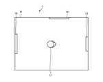
- FIG. 1 is a diagram illustrating a configuration example of a power transmission system according to a first embodiment.
- FIG. 2 is a block diagram showing a configuration example of the power transmission device according to the first embodiment.
- FIG. 3 is a block diagram illustrating a configuration example of the power receiving device according to the first embodiment.
- FIG. 4 is a diagram for explaining a method of controlling the radio wave control board according to the first embodiment.
- FIG. 5 is a diagram showing an example of the configuration of the radio wave control board according to the first embodiment.
- FIG. 6 is a diagram showing a configuration example of a unit element according to the first embodiment.
- FIG. 7 is a diagram for explaining a method of controlling the reflection and refraction angle of the radio wave control plate according to the first embodiment.
- FIG. 1 is a diagram illustrating a configuration example of a power transmission system according to a first embodiment.
- FIG. 2 is a block diagram showing a configuration example of the power transmission device according to the first embodiment.
- FIG. 3 is
- FIG. 8 is a diagram for explaining a method of controlling the reflection and refraction angle of the radio wave control plate according to the first embodiment.
- FIG. 9 is a block diagram illustrating a configuration example of a power transmission device according to a modification of the first embodiment.
- FIG. 10 is a diagram for explaining a method of installing a radio wave control board according to the second embodiment.
- FIG. 11 is a diagram for explaining the power transmission method according to the third embodiment.
- FIG. 12 is a diagram for explaining the power transmission method according to the third embodiment.
- FIG. 13 is a diagram for explaining the power transmission method according to the fourth embodiment.
- FIG. 14 is a diagram for explaining the power transmission method according to the fourth embodiment.
- FIG. 15 is a diagram for explaining the power transmission method according to the fifth embodiment.
- FIG. 16 is a diagram for explaining the power transmission method according to the fifth embodiment.
- an XYZ orthogonal coordinate system is set, and the positional relationship of each part will be explained with reference to this XYZ orthogonal coordinate system.
- the direction parallel to the X-axis in the horizontal plane is the X-axis direction
- the direction parallel to the Y-axis in the horizontal plane perpendicular to the X-axis is the Y-axis direction
- the direction parallel to the Z-axis orthogonal to the horizontal plane is the Z-axis direction.
- a plane including the X axis and the Y axis is appropriately referred to as an XY plane.
- a plane including the X axis and the Z axis is appropriately referred to as an XZ plane.
- a plane including the Y axis and the Z axis is appropriately referred to as a YZ plane.
- the XY plane is parallel to the horizontal plane.
- the XY plane, the XZ plane, and the YZ plane are orthogonal to each other.
- FIG. 1 is a diagram illustrating a configuration example of a power transmission system according to a first embodiment.
- the power transmission system 1 includes a power transmission device 10, a power reception device 12, and a radio wave control board 14.
- the power transmission system 1 is a space transmission type wireless power transmission system that transmits power using radio waves as electric power.
- the power transmission system 1 is, for example, a retrodirective spatial transmission type wireless power transmission system.
- the power transmission system 1 may be installed in a predetermined space R indoors or outdoors.
- FIG. 2 is a block diagram showing a configuration example of the power transmission device according to the first embodiment.
- the power transmission device 10 includes an antenna section 20, a storage section 22, and a control section 24.
- the antenna section 20 is configured to transmit radio waves (for example, microwaves).
- the antenna unit 20 is configured to receive a pilot signal from the power receiving device 12 for detecting the position of an obstacle that is located between the power transmitting device 10 and the power receiving device 12 and whose position changes.
- the antenna section 20 may be, for example, an array antenna including a plurality of antenna elements.
- the storage unit 22 is a memory that stores various information.
- the storage unit 22 is configured to store information such as the calculation contents and programs of the control unit 24, for example.
- the storage unit 22 stores, for example, information regarding the radio wave control board 14 included in the power transmission system 1.
- the storage unit 22 stores information regarding the installation position and size of the radio wave control board 14.
- the storage unit 22 may include, for example, at least one of a RAM (Random Access Memory), a main storage device such as a ROM (Read Only Memory), and an external storage device such as an HDD (Hard Disk Drive). .
- the control unit 24 is configured to control the operation of each part of the power transmission device 10.
- the control unit 24 is realized by, for example, a CPU (Central Processing Unit), an MPU (Micro Processing Unit), or the like executing a program stored in the storage unit 22 using a RAM or the like as a work area.
- the control unit 24 may be realized by, for example, an integrated circuit such as an ASIC (Application Specific Integrated Circuit) or an FPGA (Field Programmable Gate Array).
- the control unit 24 may be realized by a combination of hardware and software.
- the control unit 24 includes a radio wave power transmission unit 30, a signal reception unit 32, and a position detection unit 34.
- the radio wave power transmitting unit 30 is configured to generate radio waves for transmitting power to the power receiving device 12.
- the radio wave power transmission section 30 is configured to control the antenna section 20 to transmit radio waves toward the power receiving device 12 .
- the radio wave power transmission section 30 is configured to control the antenna section 20 and transmit radio waves toward the radio wave control board 14 .
- the radio wave power transmission section 30 is configured to transmit radio waves in a direction where no obstacle exists, based on the calculation result of the position of the obstacle by the position detection section 34. In the example shown in FIG. 1, the radio wave power transmission unit 30 is configured to transmit radio waves in a direction where the user U detected by the position detection unit 34 does not exist.
- the signal receiving unit 32 is configured to receive a pilot signal from the power receiving device 12.
- the signal receiving section 32 is configured to control the antenna section 20 to receive signals.
- the position detection unit 34 detects the position of an obstacle located between the power transmission device 10 and the power reception device 12.
- the position detection unit 34 detects the position of an obstacle located between the power transmission device 10 and the power reception device 12, for example, based on the pilot signal received by the signal reception unit 32. In the example shown in FIG. 1, the position detection unit 34 detects the position of the user U who is located between the power transmission device 10 and the power reception device 12.
- FIG. 3 is a block diagram illustrating a configuration example of the power receiving device according to the first embodiment.
- the power receiving device 12 includes an antenna section 40, a storage section 42, and a control section 44.
- the antenna section 40 is configured to receive radio waves transmitted from the power transmission device 10.
- the antenna section 40 is configured to transmit a pilot signal to the power transmission device 10.
- the antenna section 40 may be, for example, an array antenna including a plurality of antenna elements.
- the storage unit 42 is a memory that stores various information.
- the storage unit 42 is configured to store information such as the calculation contents and programs of the control unit 44, for example.
- the storage unit 42 stores information regarding the power transmission device 10, for example.
- the storage unit 42 may include, for example, at least one of a RAM, a main storage device such as a ROM, and an external storage device such as an HDD.
- the control unit 44 is configured to control the operation of each part of the power receiving device 12.
- the control unit 44 is realized by, for example, executing a program stored in the storage unit 42 using a RAM or the like as a work area by a CPU, an MPU, or the like.
- the control unit 44 may be realized by, for example, an integrated circuit such as an ASIC or an FPGA.
- the control unit 44 may be realized by a combination of hardware and software.
- the control unit 44 includes a radio wave receiving unit 50 and a signal transmitting unit 52.
- the radio wave receiving unit 50 is configured to control the antenna unit 40 to receive radio waves.
- the signal transmitter 52 is configured to generate a pilot signal for transmitting power to the power transmitting device 10.
- the signal transmitting unit 52 is configured to control the antenna unit 20 to transmit a pilot signal toward the power transmitting device 10.
- the radio wave control board 14 is configured to reflect, transmit, or refract received radio waves.
- the radio wave control board 14 is configured to be able to control the direction of reflection and refraction of radio waves received by applied voltage or the like.
- the radio wave control board 14 is configured to be able to change the intensity of the received radio waves when reflecting, transmitting, or refracting them.
- FIG. 4 is a diagram for explaining a method of controlling the radio wave control board according to the first embodiment. As shown in FIG. 4, a control device 60 is connected to the radio wave control board 14 via a wired or wireless network. The control device 60 is configured to be able to apply voltage to the radio wave control board 14 .
- the radio wave control board 14 is configured to be able to switch the functions of reflection, transmission, refraction, and absorption of received radio waves depending on the applied voltage.
- the radio wave control board 14 includes a radio wave refraction plate, a radio wave reflection plate, a radio wave transmission plate, a radio wave absorption plate, and the like.
- FIG. 5 is a diagram showing an example of the configuration of the radio wave control board according to the first embodiment.
- the radio wave control board 14 includes a plurality of unit elements 70.
- the unit elements 70 can be arranged two-dimensionally.
- the unit elements 70 are arranged so that the phase changes along the X-axis direction.
- the unit elements 70 are arranged so that the phase changes along the Y-axis direction.
- the radio wave control board 14 includes, for example, a plurality of unit elements 70 having different transmission phases.
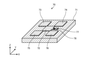
- FIG. 6 is a diagram showing a configuration example of a unit element according to the first embodiment.
- the unit element 70 includes a substrate 71, a conductor 72, a conductor 73, a conductor 74, a conductor 75, a conductor 76, a power supply section 77, and a diode 78.
- the substrate 71 is a dielectric substrate.
- the substrate 71 has, for example, a rectangular upper surface and a lower surface, but is not limited thereto.
- the conductors 72 to 76 are formed on the upper surface of the substrate 71.
- the conductor 72 and the conductors 73 to 76 are each electromagnetically connected.
- the power supply section 77 is formed on the upper surface of the substrate 71.
- the power supply section 77 is electromagnetically connected to the conductor 72.
- a diode 78 is electromagnetically connected between the power supply section 77 and the conductor 72.
- the diode 78 is, for example, a PIN diode, but is not limited thereto.
- the power supply section 77 is configured to receive voltage from the control device 60 (see FIG. 4).
- the unit element 70 is configured so that the frequency band, phase change amount, etc. of the radio wave to be controlled change by applying a voltage from the control device 60.
- the control device 60 can control the reflection angle, refraction angle, phase change amount, etc. of the unit element 70 by controlling the voltage applied to the power supply section 77 .
- FIG. 7 and FIG. 8 are diagrams for explaining a method of controlling the reflection and refraction angle of the radio wave control plate according to the first embodiment.
- the power transmission device 10 transmits radio waves W1 to the radio wave control board 14.
- the radio wave control board 14 reflects the radio wave W1 toward the power receiving device 12 as a reflected radio wave W2.
- the control device 60 sets the reflection angle of the radio wave W1 of the radio wave control board 14 in advance based on the positional relationship among the power transmitting device 10, the power receiving device 12, and the radio wave control board 14. Specifically, the control device 60 scans the reflection angle of the radio wave control board 14 and calculates the reflection angle at which the maximum power is obtained.
- the control device 60 sets the reflection angle of the radio wave control board 14 to the calculated reflection angle.
- the power receiving device 12 can appropriately receive the reflected radio waves W2 from the radio wave control board 14, so that the maximum power can be obtained.
- the radio wave control board 14 has been described as one that reflects the radio waves W1, but the present disclosure is not limited thereto. Even when the radio wave control board 14 transmits or refracts the radio wave W1, the control device 60 can control the transmission angle or refraction angle of the radio wave control board 14 so as to obtain maximum power.
- radio waves can be transmitted in a direction where user U does not exist.
- the radio waves can be appropriately transmitted from the power transmitting device to the power receiving device so that the human body is not irradiated with the radio waves.
- FIG. 9 is a block diagram illustrating a configuration example of a power transmission device according to a modification of the first embodiment.
- the power transmission device 10A differs from the power transmission device 10 shown in FIG. 2 in that the power transmission device 10A includes a sensor section 26, and that the control section 24A includes an obstacle detection section 36.
- the sensor unit 26 is a sensor that can detect a moving object (for example, a human body) that may become an obstacle to the radio waves transmitted by the power transmission device 10A.
- the sensor unit 26 may be realized, for example, by a sensor that detects a moving object around the power transmission device 10A using electromagnetic waves, ultrasonic waves, or the like.
- the sensor unit 26 may be, for example, an imaging device including at least one of an infrared camera and a visible light camera.
- the obstacle detection unit 36 causes the sensor unit 26 to detect obstacles around the power transmission device 10A.
- the obstacle detection unit 36 detects the position of an obstacle whose position changes based on the detection result of the sensor unit 26.
- the radio wave power transmission unit 30A controls the direction of power transmission of radio waves based on the obstacle detection result of the obstacle detection unit 36. Specifically, the radio wave power transmitting unit 30A transmits the power from the power transmitting device 10 to the power receiving device 12 via the radio wave control board 14 based on the obstacle detection result of the obstacle detection unit 36 so that radio waves are not irradiated to the obstacle. Calculate the radio wave transmission path to. Then, the radio wave power transmitting unit 30A transmits the radio waves according to the calculated transmission path.
- the position of the human body can be detected more accurately by the sensor unit 26.
- the sensor unit 26 it is possible to more appropriately transmit the radio waves from the power transmitting device to the power receiving device so that the human body is not irradiated with the radio waves.
- FIG. 10 is a diagram for explaining a method of installing a radio wave control board according to the second embodiment.
- the size of the radio control board 14 is determined based on the Fresnel zone defined according to the positional relationship between the power transmitting device 10, the power receiving device 12, and the radio control board 14. In this embodiment, a region where radio waves strengthen each other is called an odd-numbered Fresnel zone, and a region where radio waves weaken each other is called an even-numbered Fresnel zone.
- Fresnel zone The definition of the Fresnel zone according to the second embodiment will be explained.
- the center point (geometric center point) of the radio wave control board 14 is defined as center point C.
- the straight line distance between the power transmission device 10 and the center point C be d1 .
- the straight line distance between the power receiving device 12 and the center point C be d2 .
- a circle whose radius is defined by the following equation (1) on a plane, centering on the center point C.
- n is a natural number and ⁇ is the wavelength of the radio wave.
- the annular portion in the range from radius Rn-1 to radius Rn is defined as the n-th Fresnel zone.
- a first Fresnel zone 81, a second Fresnel zone 82, a third Fresnel zone 83, a fourth Fresnel zone 84, a fifth Fresnel zone 85, and a sixth Fresnel zone 86 are It is shown.
- the range of a circle with radius R1 becomes the first Fresnel zone 81.
- the range of the annular portion between the circle with radius R1 and the circle with radius R2 becomes the second Fresnel zone 82.
- the size of the radio wave control board 14 is set to be at least twice the radius of the first Fresnel zone 81.
- the radius of the nth Fresnel zone is also called the nth Fresnel radius.
- the size of the radio wave control board 14 may be set within a range of ⁇ 25% of twice the first Fresnel radius.
- the distance between the user U and the power receiving device 12 is short, there is a possibility that the user U will be irradiated with radio waves from the radio wave control board 14. Therefore, in this embodiment, by controlling the amount of phase change of each unit element included in the radio wave control board 14, the beam width of the radio waves from the radio wave control board 14 is narrowed, and the radio waves are irradiated to the user U. Prevent this from happening.
- control device 60 controls each component included in the radio wave control board 14 so that the phase between the power transmission device 10 and the radio wave control board 14 matches the phase between the radio wave control board 14 and the power receiving device 12.
- Control unit elements For example, the control device 60 controls the amount of phase change of each unit element included in the radio wave control board 14 so that the amount of phase change of each unit element changes concentrically.
- the control device 60 may control only the unit elements located in the even-numbered Fresnel zone among the unit elements included in the radio wave control board 14. Alternatively, the control device 60 may control the unit elements located in the even Fresnel zone and the unit elements located in the odd Fresnel zone to be out of phase by 180 degrees. In this embodiment, only the unit elements located in the even-order Fresnel zone are controlled, or the phases of the unit elements located in the multi-order Fresnel zone and the unit elements located in the odd-order Fresnel zone are shifted by 180 degrees. This is called a Fresnel zone plate. In this embodiment, each unit element included in the radio wave control board 14 is a Fresnel zone plate, so that the beam width of the radio waves can be narrowed and control can be performed so that the user U is not irradiated with the radio waves.
- FIG. 11 and FIG. 12 are diagrams for explaining the power transmission method according to the third embodiment.
- the power transmitting device 10 transmits the radio wave W1 toward the radio wave control board 14 so that the user U1 is not irradiated with the radio wave W1, and the power receiving device 12 receives the reflected radio wave W2 from the radio wave control board 14.
- the user U2 may be irradiated with the radio wave W1 that protrudes from the radio wave control board 14 and is reflected by a wall or the like.
- the power transmission device 10 makes the beam width of the radio wave W1 narrower than the radio wave control board 14 to prevent the radio wave W1 from protruding from the radio wave control board 14.
- the radio wave power transmission unit 30 refers to the size of the radio wave control board 14 stored in the storage unit 22 and controls the beam width of the radio wave W1 to be narrower than the size of the radio wave control board 14.
- the third embodiment can prevent the user U2 from being irradiated with the radio wave W1 that protrudes from the radio wave control board 14 and is reflected by a wall or the like.
- the power transmission device 10 may narrow the beam width of the radio wave W1 when detecting that the radio wave W1 has protruded from the radio wave control board 14.
- the control device 60 of the radio wave control board 14 determines that the radio wave W1 is transmitted to the radio wave control board 14. It is best to judge that it is protruding from the outside. For example, when the control device 60 determines that the radio wave W1 is protruding from the radio wave control board 14, it transmits information indicating that the radio wave W1 is protruding from the radio wave control board 14. Thereby, the power transmission device 10 can detect that the radio wave W1 has protruded from the radio wave control board 14.
- FIG. 13 and FIG. 14 are diagrams for explaining the power transmission method according to the fourth embodiment.
- FIG. 13 consider a situation where a user U1, a user U2, and a user U3 are located in a space R in which the power transmission system 1 is installed.
- the number of users located in the space R increases, there is a possibility that one of the users (for example, user U3) will be irradiated with the radio wave W1.
- a plurality of radio wave control boards are installed in the space R, such as the radio wave control board 14-1 and the radio wave control board 14-2.
- the power transmission device 10 transmits the radio wave W1 toward the radio wave control board 14-1.
- the radio wave control board 14-1 transmits a reflected radio wave W2 that has reflected the radio wave W1 to the radio wave control board 14-2.
- the radio wave control board 14-2 transmits the reflected radio wave W3, which is the reflected radio wave W2, to the power receiving device 12.
- the fourth embodiment can prevent the human body from being irradiated with radio waves between the power transmitting device 10 and the power receiving device 12.
- radio wave control board 14-1 and the radio wave control board 14-2 are installed in the space R, but the present disclosure is not limited thereto.
- Three or more radio wave control boards may be installed in the space R.
- an upper limit on the number of radio wave control boards installed in the space R may be set within a range where power attenuation is allowable.
- FIG. 15 and FIG. 16 are diagrams for explaining the power transmission method according to the fifth embodiment.
- the power transmission device 10 transmits the radio wave W1 toward the radio wave control board 14-1 and the radio wave control board 14-2.
- the radio wave control board 14-1 transmits a reflected radio wave W2 that reflects the radio wave W1 to the power receiving device 12.
- the radio wave control board 14-2 transmits a reflected radio wave W4 that reflects the radio wave W1 to the power receiving device 12.
- each unit element of the radio wave control board 14-1 is controlled to absorb the radio wave W1 so that the user U1 is not irradiated with the reflected radio wave.
- the position detection unit 34 of the control unit 24 of the power transmission device 10 detects that the user U1 is located on the straight line connecting the power reception device 12 and the radio wave control board 14-1
- the position detection unit 34 of the control unit 24 of the power transmission device 10 detects that the user Information including the position information of U1 is transmitted to the control device 60 of the radio wave control board 14-1.
- the control device 60 controls each unit element of the radio wave control board 14-1 to absorb the radio wave W1 so that the user U1 is not irradiated with the radio wave based on the position information of the user U1.
- the fifth embodiment can prevent the human body from being irradiated with radio waves between the power transmitting device 10 and the power receiving device 12.
- Power transmission system 10 Power transmission device 12
- Power reception device 14 Radio wave control board 20, 40 Antenna section 22, 42 Storage section 24, 44 Control section 30
- Radio wave power transmission section 32
- Signal reception section 34
- Position detection section 50
- Radio wave reception section 52 Signal transmission section
Landscapes
- Engineering & Computer Science (AREA)
- Computer Networks & Wireless Communication (AREA)
- Power Engineering (AREA)
- Physics & Mathematics (AREA)
- Electromagnetism (AREA)
- Mobile Radio Communication Systems (AREA)
Priority Applications (1)
| Application Number | Priority Date | Filing Date | Title |
|---|---|---|---|
| JP2024522998A JPWO2023228693A1 (https=) | 2022-05-24 | 2023-05-01 |
Applications Claiming Priority (2)
| Application Number | Priority Date | Filing Date | Title |
|---|---|---|---|
| JP2022-084326 | 2022-05-24 | ||
| JP2022084326 | 2022-05-24 |
Publications (1)
| Publication Number | Publication Date |
|---|---|
| WO2023228693A1 true WO2023228693A1 (ja) | 2023-11-30 |
Family
ID=88919013
Family Applications (1)
| Application Number | Title | Priority Date | Filing Date |
|---|---|---|---|
| PCT/JP2023/017095 Ceased WO2023228693A1 (ja) | 2022-05-24 | 2023-05-01 | 電力伝送システムおよび電力伝送方法 |
Country Status (2)
| Country | Link |
|---|---|
| JP (1) | JPWO2023228693A1 (https=) |
| WO (1) | WO2023228693A1 (https=) |
Cited By (1)
| Publication number | Priority date | Publication date | Assignee | Title |
|---|---|---|---|---|
| WO2025164732A1 (ja) * | 2024-01-31 | 2025-08-07 | 京セラ株式会社 | 電波制御板の制御方法、電波制御板の制御装置及びプログラム |
Citations (5)
| Publication number | Priority date | Publication date | Assignee | Title |
|---|---|---|---|---|
| US20180198320A1 (en) * | 2017-01-12 | 2018-07-12 | David R. Criswell | System and method for transmitting and receiving power wirelessly |
| US20190372399A1 (en) * | 2016-09-19 | 2019-12-05 | Samsung Electronics Co., Ltd. | Wireless power transmitter and control method therefor |
| CN110635582A (zh) * | 2019-08-30 | 2019-12-31 | 同济大学 | 一种电磁回波激励放大的无线能量传输系统与方法 |
| WO2021199504A1 (ja) * | 2020-03-31 | 2021-10-07 | Agc株式会社 | 無線伝達システム |
| WO2022091660A1 (ja) * | 2020-10-28 | 2022-05-05 | 住友電気工業株式会社 | 反射ユニット及び無線伝送システム |
Family Cites Families (1)
| Publication number | Priority date | Publication date | Assignee | Title |
|---|---|---|---|---|
| JP2020145790A (ja) * | 2019-03-04 | 2020-09-10 | 日本電信電話株式会社 | 無線電力伝送システム、無線電力伝送方法及び無線電力伝送装置 |
-
2023
- 2023-05-01 JP JP2024522998A patent/JPWO2023228693A1/ja active Pending
- 2023-05-01 WO PCT/JP2023/017095 patent/WO2023228693A1/ja not_active Ceased
Patent Citations (5)
| Publication number | Priority date | Publication date | Assignee | Title |
|---|---|---|---|---|
| US20190372399A1 (en) * | 2016-09-19 | 2019-12-05 | Samsung Electronics Co., Ltd. | Wireless power transmitter and control method therefor |
| US20180198320A1 (en) * | 2017-01-12 | 2018-07-12 | David R. Criswell | System and method for transmitting and receiving power wirelessly |
| CN110635582A (zh) * | 2019-08-30 | 2019-12-31 | 同济大学 | 一种电磁回波激励放大的无线能量传输系统与方法 |
| WO2021199504A1 (ja) * | 2020-03-31 | 2021-10-07 | Agc株式会社 | 無線伝達システム |
| WO2022091660A1 (ja) * | 2020-10-28 | 2022-05-05 | 住友電気工業株式会社 | 反射ユニット及び無線伝送システム |
Cited By (1)
| Publication number | Priority date | Publication date | Assignee | Title |
|---|---|---|---|---|
| WO2025164732A1 (ja) * | 2024-01-31 | 2025-08-07 | 京セラ株式会社 | 電波制御板の制御方法、電波制御板の制御装置及びプログラム |
Also Published As
| Publication number | Publication date |
|---|---|
| JPWO2023228693A1 (https=) | 2023-11-30 |
Similar Documents
| Publication | Publication Date | Title |
|---|---|---|
| US8643536B2 (en) | Radio frequency positioning system for vehicles | |
| JP7211398B2 (ja) | 導波管スロットアンテナ | |
| JP2022059609A (ja) | 高速ota生産ラインテストプラットフォーム | |
| JP2006153878A (ja) | 侵入物検知装置および電波反射器 | |
| JP2011257350A (ja) | レーダ装置 | |
| TW202224268A (zh) | 反射單元及無線傳送系統 | |
| JPWO2022091660A5 (https=) | ||
| US12095286B2 (en) | Power supply system, power supply device, and power supply method | |
| WO2023228693A1 (ja) | 電力伝送システムおよび電力伝送方法 | |
| US8830114B2 (en) | Mobile object detecting apparatus | |
| JP2024053123A (ja) | 制御装置 | |
| JP7065423B2 (ja) | アンテナ装置 | |
| JP3778056B2 (ja) | 侵入物検知装置 | |
| JP4773759B2 (ja) | 障害物検知レーダシステム | |
| JP2006133108A (ja) | レーダシステム、物体検出方法、レーダ装置、電波反射体 | |
| EP4404385B1 (en) | ANTENNA DEVICE | |
| US20240213809A1 (en) | Wireless power transmission system for acting upon mobile electronic devices | |
| JP2017125765A (ja) | 対象物検出装置 | |
| KR102951777B1 (ko) | 표적의 수직 각도를 검출하는 검출 장치 및 방법 | |
| JP2835705B2 (ja) | マイクロ波による物体検出方法 | |
| JP2013070366A (ja) | 空中線 | |
| US20250093463A1 (en) | Radar system, method, and storage medium | |
| RU2263930C1 (ru) | Лазерно-радиолокационная станция | |
| JP7379219B2 (ja) | レーダシステムの試験装置及び試験設備 | |
| CN112313531A (zh) | 一种测距装置及其扫描视场的控制方法 |
Legal Events
| Date | Code | Title | Description |
|---|---|---|---|
| 121 | Ep: the epo has been informed by wipo that ep was designated in this application |
Ref document number: 23811571 Country of ref document: EP Kind code of ref document: A1 |
|
| WWE | Wipo information: entry into national phase |
Ref document number: 2024522998 Country of ref document: JP |
|
| NENP | Non-entry into the national phase |
Ref country code: DE |
|
| 122 | Ep: pct application non-entry in european phase |
Ref document number: 23811571 Country of ref document: EP Kind code of ref document: A1 |