WO2023228693A1 - Power transmission system and power transmission method - Google Patents
Power transmission system and power transmission method Download PDFInfo
- Publication number
- WO2023228693A1 WO2023228693A1 PCT/JP2023/017095 JP2023017095W WO2023228693A1 WO 2023228693 A1 WO2023228693 A1 WO 2023228693A1 JP 2023017095 W JP2023017095 W JP 2023017095W WO 2023228693 A1 WO2023228693 A1 WO 2023228693A1
- Authority
- WO
- WIPO (PCT)
- Prior art keywords
- radio wave
- power transmission
- control board
- wave control
- power
- Prior art date
Links
- 230000005540 biological transmission Effects 0.000 title claims abstract description 126
- 238000000034 method Methods 0.000 title claims description 24
- 238000010586 diagram Methods 0.000 description 28
- 238000001514 detection method Methods 0.000 description 17
- 239000004020 conductor Substances 0.000 description 10
- 230000004048 modification Effects 0.000 description 6
- 238000012986 modification Methods 0.000 description 6
- 239000000758 substrate Substances 0.000 description 6
- 238000005516 engineering process Methods 0.000 description 4
- 238000010521 absorption reaction Methods 0.000 description 2
- 239000000470 constituent Substances 0.000 description 1
- 230000006870 function Effects 0.000 description 1
- 238000003384 imaging method Methods 0.000 description 1
- 238000009434 installation Methods 0.000 description 1
- 230000008054 signal transmission Effects 0.000 description 1
- 238000006467 substitution reaction Methods 0.000 description 1
Images


Classifications
-
- H—ELECTRICITY
- H01—ELECTRIC ELEMENTS
- H01Q—ANTENNAS, i.e. RADIO AERIALS
- H01Q15/00—Devices for reflection, refraction, diffraction or polarisation of waves radiated from an antenna, e.g. quasi-optical devices
- H01Q15/14—Reflecting surfaces; Equivalent structures
-
- H—ELECTRICITY
- H02—GENERATION; CONVERSION OR DISTRIBUTION OF ELECTRIC POWER
- H02J—CIRCUIT ARRANGEMENTS OR SYSTEMS FOR SUPPLYING OR DISTRIBUTING ELECTRIC POWER; SYSTEMS FOR STORING ELECTRIC ENERGY
- H02J50/00—Circuit arrangements or systems for wireless supply or distribution of electric power
- H02J50/20—Circuit arrangements or systems for wireless supply or distribution of electric power using microwaves or radio frequency waves
-
- H—ELECTRICITY
- H02—GENERATION; CONVERSION OR DISTRIBUTION OF ELECTRIC POWER
- H02J—CIRCUIT ARRANGEMENTS OR SYSTEMS FOR SUPPLYING OR DISTRIBUTING ELECTRIC POWER; SYSTEMS FOR STORING ELECTRIC ENERGY
- H02J50/00—Circuit arrangements or systems for wireless supply or distribution of electric power
- H02J50/50—Circuit arrangements or systems for wireless supply or distribution of electric power using additional energy repeaters between transmitting devices and receiving devices
Abstract
This power transmission system includes: a power transmitting device that transmits radio waves; a power receiving device that receives radio waves; and a radio-wave control plate that receives the radio waves transmitted by the power transmitting device, and that changes the transmission direction of the radio waves so that the same are directed toward the power receiving device.
Description
本開示は、電力伝送システムおよび電力伝送方法に関する。
The present disclosure relates to a power transmission system and a power transmission method.
空間伝送型ワイヤレス電力伝送において、強い電波が発射されることが想定されるため、人体が存在する空間内で使用する場合に、電波が人体に向けて発射されることを回避する技術が知られている。例えば、特許文献1には、人体を回避した電力伝送技術として、受電装置から発せられたパイロット信号をもとに送電方向を決定するレトロディレクティブ方式の空間伝送型ワイヤレス電力伝送技術が記載されている。
Since it is assumed that strong radio waves are emitted in space-based wireless power transmission, there are known technologies to prevent radio waves from being emitted towards the human body when used in a space where the human body is present. ing. For example, Patent Document 1 describes a retrodirective spatial transmission type wireless power transmission technology that determines the power transmission direction based on a pilot signal emitted from a power receiving device as a power transmission technology that avoids the human body. .
本開示の電力伝送システムは、電波を送電する送電装置と、前記電波を受電する受電装置と、前記送電装置が送電した前記電波を受けて、前記電波の伝送方向を前記受電装置に向けて変化させる電波制御板と、を含む。
The power transmission system of the present disclosure includes a power transmission device that transmits power, a power reception device that receives the radio waves, and a power transmission direction that changes the transmission direction of the radio waves toward the power reception device upon receiving the radio waves transmitted by the power transmission device. and a radio wave control board.
本開示の電力伝送方法は、送電装置から電波を送電させるステップと、前記送電装置が送電した前記電波を受ける電波制御板を制御して、前記電波の伝送方向を受電装置に向けて変化させるステップ、前記受電装置で前記電波を受信させるステップと、を含む。
The power transmission method of the present disclosure includes the steps of transmitting radio waves from a power transmission device, and controlling a radio wave control board that receives the radio waves transmitted by the power transmission device to change the transmission direction of the radio waves toward a power receiving device. , causing the power receiving device to receive the radio waves.
以下、添付図面を参照して、本発明に係る実施形態を詳細に説明する。なお、この実施形態により本発明が限定されるものではなく、また、以下の実施形態において、同一の部位には同一の符号を付することにより重複する説明を省略する。
Hereinafter, embodiments of the present invention will be described in detail with reference to the accompanying drawings. Note that the present invention is not limited to this embodiment, and in the following embodiments, the same parts are given the same reference numerals and redundant explanations will be omitted.
以下の説明においては、XYZ直交座標系を設定し、このXYZ直交座標系を参照しつつ各部の位置関係について説明する。水平面内のX軸と平行な方向をX軸方向とし、X軸と直交する水平面内のY軸と平行な方向をY軸方向とし、水平面と直交するZ軸と平行な方向をZ軸方向とする。X軸及びY軸を含む平面を適宜、XY平面と称する。X軸及びZ軸を含む平面を適宜、XZ平面と称する。Y軸及びZ軸を含む平面を適宜、YZ平面と称する。XY平面は、水平面と平行である。XY平面とXZ平面とYZ平面とは直交する。
In the following description, an XYZ orthogonal coordinate system is set, and the positional relationship of each part will be explained with reference to this XYZ orthogonal coordinate system. The direction parallel to the X-axis in the horizontal plane is the X-axis direction, the direction parallel to the Y-axis in the horizontal plane perpendicular to the X-axis is the Y-axis direction, and the direction parallel to the Z-axis orthogonal to the horizontal plane is the Z-axis direction. do. A plane including the X axis and the Y axis is appropriately referred to as an XY plane. A plane including the X axis and the Z axis is appropriately referred to as an XZ plane. A plane including the Y axis and the Z axis is appropriately referred to as a YZ plane. The XY plane is parallel to the horizontal plane. The XY plane, the XZ plane, and the YZ plane are orthogonal to each other.
[第1実施形態]
(電力伝送システム)
図1を用いて、第1実施形態に係る電力伝送システムの構成例について説明する。図1は、第1実施形態に係る電力伝送システムの構成例を示す図である。 [First embodiment]
(power transmission system)
A configuration example of the power transmission system according to the first embodiment will be described using FIG. 1. FIG. 1 is a diagram illustrating a configuration example of a power transmission system according to a first embodiment.
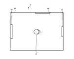
図1に示すように、電力伝送システム1は、送電装置10と、受電装置12と、電波制御板14と、を含む。本実施形態では、電力伝送システム1は、電波を電力として送電する空間伝送型のワイヤレス電力伝送システムである。電力伝送システム1は、例えば、レトロディレクティブ方式の空間伝送型のワイヤレス電力伝送システムである。電力伝送システム1は、屋内または屋外の所定の空間R内に設置され得る。
As shown in FIG. 1, the power transmission system 1 includes a power transmission device 10, a power reception device 12, and a radio wave control board 14. In this embodiment, the power transmission system 1 is a space transmission type wireless power transmission system that transmits power using radio waves as electric power. The power transmission system 1 is, for example, a retrodirective spatial transmission type wireless power transmission system. The power transmission system 1 may be installed in a predetermined space R indoors or outdoors.
(送電装置)
図2を用いて、第1実施形態に係る送電装置の構成例について説明する。図2は、第1実施形態に係る送電装置の構成例を示すブロック図である。 (Power transmission equipment)
A configuration example of the power transmission device according to the first embodiment will be described using FIG. 2. FIG. 2 is a block diagram showing a configuration example of the power transmission device according to the first embodiment.
図2に示すように、送電装置10は、アンテナ部20と、記憶部22と、制御部24と、を備える。
As shown in FIG. 2, the power transmission device 10 includes an antenna section 20, a storage section 22, and a control section 24.
アンテナ部20は、電波(例えば、マイクロ波)を送電するように構成されている。アンテナ部20は、送電装置10と受電装置12との間に位置する位置変動する障害物の位置を検出するためのパイロット信号を受電装置12から受信するように構成されている。アンテナ部20は、例えば、複数のアンテナ素子を含むアレーアンテナであり得る。
The antenna section 20 is configured to transmit radio waves (for example, microwaves). The antenna unit 20 is configured to receive a pilot signal from the power receiving device 12 for detecting the position of an obstacle that is located between the power transmitting device 10 and the power receiving device 12 and whose position changes. The antenna section 20 may be, for example, an array antenna including a plurality of antenna elements.
記憶部22は、各種の情報を記憶するメモリである。記憶部22は、例えば、制御部24の演算内容およびプログラムなどの情報を記憶するように構成されている。記憶部22は、例えば、電力伝送システム1に含まれる電波制御板14に関する情報を記憶している。記憶部22は、電波制御板14の設置位置およびサイズに関する情報を記憶している。記憶部22は、例えば、RAM(Random Access Memory)と、ROM(Read Only Memory)のような主記憶装置と、HDD(Hard Disk Drive)などの外部記憶装置とのうち、少なくとも1つを含み得る。
The storage unit 22 is a memory that stores various information. The storage unit 22 is configured to store information such as the calculation contents and programs of the control unit 24, for example. The storage unit 22 stores, for example, information regarding the radio wave control board 14 included in the power transmission system 1. The storage unit 22 stores information regarding the installation position and size of the radio wave control board 14. The storage unit 22 may include, for example, at least one of a RAM (Random Access Memory), a main storage device such as a ROM (Read Only Memory), and an external storage device such as an HDD (Hard Disk Drive). .
制御部24は、送電装置10の各部の動作を制御するように構成されている。制御部24は、例えば、CPU(Central Processing Unit)やMPU(Micro Processing Unit)等によって、記憶部22に記憶されたプログラムがRAM等を作業領域として実行されることにより実現される。制御部24は、例えば、ASIC(Application Specific Integrated Circuit)やFPGA(Field Programmable Gate Array)等の集積回路により実現されてもよい。制御部24は、ハードウェアと、ソフトウェアとの組み合わせで実現されてもよい。
The control unit 24 is configured to control the operation of each part of the power transmission device 10. The control unit 24 is realized by, for example, a CPU (Central Processing Unit), an MPU (Micro Processing Unit), or the like executing a program stored in the storage unit 22 using a RAM or the like as a work area. The control unit 24 may be realized by, for example, an integrated circuit such as an ASIC (Application Specific Integrated Circuit) or an FPGA (Field Programmable Gate Array). The control unit 24 may be realized by a combination of hardware and software.
制御部24は、電波送電部30と、信号受信部32と、位置検出部34と、を備える。
The control unit 24 includes a radio wave power transmission unit 30, a signal reception unit 32, and a position detection unit 34.
電波送電部30は、受電装置12に送電するための電波を生成するように構成されている。電波送電部30は、アンテナ部20を制御して、受電装置12に向けて電波を送電させるように構成されている。電波送電部30は、アンテナ部20を制御して、電波制御板14に向けて電波を送電するように構成されている。電波送電部30は、位置検出部34による障害物の位置の算出結果に基づいて、障害物が存在しない方向に電波を送電するように構成されている。図1に示す例でいえば、電波送電部30は、位置検出部34が検出したユーザUの存在しない方向に電波を送電するように構成されている。
The radio wave power transmitting unit 30 is configured to generate radio waves for transmitting power to the power receiving device 12. The radio wave power transmission section 30 is configured to control the antenna section 20 to transmit radio waves toward the power receiving device 12 . The radio wave power transmission section 30 is configured to control the antenna section 20 and transmit radio waves toward the radio wave control board 14 . The radio wave power transmission section 30 is configured to transmit radio waves in a direction where no obstacle exists, based on the calculation result of the position of the obstacle by the position detection section 34. In the example shown in FIG. 1, the radio wave power transmission unit 30 is configured to transmit radio waves in a direction where the user U detected by the position detection unit 34 does not exist.
信号受信部32は、受電装置12からのパイロット信号を受信するように構成されている。信号受信部32は、アンテナ部20を制御して、受信させるように構成されている。
The signal receiving unit 32 is configured to receive a pilot signal from the power receiving device 12. The signal receiving section 32 is configured to control the antenna section 20 to receive signals.
位置検出部34は、送電装置10と、受電装置12との間に位置している障害物の位置を検出する。位置検出部34は、例えば、信号受信部32が受信したパイロット信号に基づいて、送電装置10と、受電装置12との間に位置している障害物の位置を検出する。位置検出部34は、図1に示す例でいえば、送電装置10と、受電装置12との間に位置しているユーザUの位置を検出する。
The position detection unit 34 detects the position of an obstacle located between the power transmission device 10 and the power reception device 12. The position detection unit 34 detects the position of an obstacle located between the power transmission device 10 and the power reception device 12, for example, based on the pilot signal received by the signal reception unit 32. In the example shown in FIG. 1, the position detection unit 34 detects the position of the user U who is located between the power transmission device 10 and the power reception device 12.
(受電装置)
図3を用いて、第1実施形態に係る受電装置の構成例について説明する。図3は、第1実施形態に係る受電装置の構成例を示すブロック図である。 (Power receiving device)
A configuration example of the power receiving device according to the first embodiment will be described using FIG. 3. FIG. 3 is a block diagram illustrating a configuration example of the power receiving device according to the first embodiment.
図3に示すように、受電装置12は、アンテナ部40と、記憶部42と、制御部44と、を備える。
As shown in FIG. 3, the power receiving device 12 includes an antenna section 40, a storage section 42, and a control section 44.
アンテナ部40は、送電装置10から送電された電波を受電するように構成されている。アンテナ部40は、パイロット信号を送電装置10に送信するように構成されている。アンテナ部40は、例えば、複数のアンテナ素子を含むアレーアンテナであり得る。
The antenna section 40 is configured to receive radio waves transmitted from the power transmission device 10. The antenna section 40 is configured to transmit a pilot signal to the power transmission device 10. The antenna section 40 may be, for example, an array antenna including a plurality of antenna elements.
記憶部42は、各種の情報を記憶するメモリである。記憶部42は、例えば、制御部44の演算内容およびプログラムなどの情報を記憶するように構成されている。記憶部42は、例えば、送電装置10に関する情報を記憶している。記憶部42は、例えば、RAMと、ROMのような主記憶装置と、HDDなどの外部記憶装置とのうち、少なくとも1つを含み得る。
The storage unit 42 is a memory that stores various information. The storage unit 42 is configured to store information such as the calculation contents and programs of the control unit 44, for example. The storage unit 42 stores information regarding the power transmission device 10, for example. The storage unit 42 may include, for example, at least one of a RAM, a main storage device such as a ROM, and an external storage device such as an HDD.
制御部44は、受電装置12の各部の動作を制御するように構成されている。制御部44は、例えば、CPUやMPU等によって、記憶部42に記憶されたプログラムがRAM等を作業領域として実行されることにより実現される。制御部44は、例えば、ASICやFPGA等の集積回路により実現されてもよい。制御部44は、ハードウェアと、ソフトウェアとの組み合わせで実現されてもよい。
The control unit 44 is configured to control the operation of each part of the power receiving device 12. The control unit 44 is realized by, for example, executing a program stored in the storage unit 42 using a RAM or the like as a work area by a CPU, an MPU, or the like. The control unit 44 may be realized by, for example, an integrated circuit such as an ASIC or an FPGA. The control unit 44 may be realized by a combination of hardware and software.
制御部44は、電波受電部50と、信号送信部52と、を備える。
The control unit 44 includes a radio wave receiving unit 50 and a signal transmitting unit 52.
電波受電部50は、アンテナ部40を制御して、電波を受電させるように構成されている。
The radio wave receiving unit 50 is configured to control the antenna unit 40 to receive radio waves.
信号送信部52は、送電装置10に送電するためのパイロット信号を生成するように構成されている。信号送信部52は、アンテナ部20を制御して、送電装置10に向けてパイロット信号を送信させるように構成されている。
The signal transmitter 52 is configured to generate a pilot signal for transmitting power to the power transmitting device 10. The signal transmitting unit 52 is configured to control the antenna unit 20 to transmit a pilot signal toward the power transmitting device 10.
(電波制御板)
電波制御板14は、受けた電波を反射させたり、透過させたり、屈折させたりするように構成されている。電波制御板14は、印加電圧等によって受けた電波の反射方向や屈折方向を制御可能に構成されている。電波制御板14は、受けた電波を反射させたり、透過させたり、屈折させたりする際の電波の強度を変更可能に構成されている。図4は、第1実施形態に係る電波制御板を制御する方法を説明するための図である。図4に示すように、電波制御板14には、有線または無線のネットワークを介して制御装置60が接続されている。制御装置60は、電波制御板14に対して、電圧を印加可能に構成されている。電波制御板14は、印加電圧によって受けた電波の反射、透過、屈折、および吸収の機能を切り替え可能に構成されている。電波制御板14は、電波屈折板、電波反射板、電波透過板、および電波吸収板などを含む。 (Radio control board)
The radiowave control board 14 is configured to reflect, transmit, or refract received radio waves. The radio wave control board 14 is configured to be able to control the direction of reflection and refraction of radio waves received by applied voltage or the like. The radio wave control board 14 is configured to be able to change the intensity of the received radio waves when reflecting, transmitting, or refracting them. FIG. 4 is a diagram for explaining a method of controlling the radio wave control board according to the first embodiment. As shown in FIG. 4, a control device 60 is connected to the radio wave control board 14 via a wired or wireless network. The control device 60 is configured to be able to apply voltage to the radio wave control board 14 . The radio wave control board 14 is configured to be able to switch the functions of reflection, transmission, refraction, and absorption of received radio waves depending on the applied voltage. The radio wave control board 14 includes a radio wave refraction plate, a radio wave reflection plate, a radio wave transmission plate, a radio wave absorption plate, and the like.
電波制御板14は、受けた電波を反射させたり、透過させたり、屈折させたりするように構成されている。電波制御板14は、印加電圧等によって受けた電波の反射方向や屈折方向を制御可能に構成されている。電波制御板14は、受けた電波を反射させたり、透過させたり、屈折させたりする際の電波の強度を変更可能に構成されている。図4は、第1実施形態に係る電波制御板を制御する方法を説明するための図である。図4に示すように、電波制御板14には、有線または無線のネットワークを介して制御装置60が接続されている。制御装置60は、電波制御板14に対して、電圧を印加可能に構成されている。電波制御板14は、印加電圧によって受けた電波の反射、透過、屈折、および吸収の機能を切り替え可能に構成されている。電波制御板14は、電波屈折板、電波反射板、電波透過板、および電波吸収板などを含む。 (Radio control board)
The radio
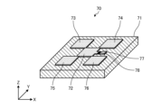
図5は、第1実施形態に係る電波制御板の構成例を示す図である。図5に示すように、電波制御板14は、複数の単位素子70を含む。
FIG. 5 is a diagram showing an example of the configuration of the radio wave control board according to the first embodiment. As shown in FIG. 5, the radio wave control board 14 includes a plurality of unit elements 70.
図5に示すように、単位素子70は、2次元に配列され得る。単位素子70は、例えば、X軸方向に沿って位相が変化するように配置されている。単位素子70は、例えば、Y軸方向に沿って位相が変化するように配置されている。単位素子70の大きさおよび形状等を変化させることで、制御する電波の周波数帯域および位相の変化量を調整し得る。本実施形態では、電波制御板14は、例えば、透過位相の異なる複数の単位素子70を含む。
As shown in FIG. 5, the unit elements 70 can be arranged two-dimensionally. For example, the unit elements 70 are arranged so that the phase changes along the X-axis direction. For example, the unit elements 70 are arranged so that the phase changes along the Y-axis direction. By changing the size, shape, etc. of the unit element 70, the amount of change in the frequency band and phase of the radio waves to be controlled can be adjusted. In this embodiment, the radio wave control board 14 includes, for example, a plurality of unit elements 70 having different transmission phases.
図6は、第1実施形態に係る単位素子の構成例を示す図である。図6に示すように、単位素子70は、基板71と、導体72と、導体73と、導体74と、導体75と、導体76と、給電部77と、ダイオード78と、を備える。
FIG. 6 is a diagram showing a configuration example of a unit element according to the first embodiment. As shown in FIG. 6, the unit element 70 includes a substrate 71, a conductor 72, a conductor 73, a conductor 74, a conductor 75, a conductor 76, a power supply section 77, and a diode 78.
基板71は、誘電体の基板である。基板71は、例えば、上面および下面が矩形形状であるが、これに限定されない。
The substrate 71 is a dielectric substrate. The substrate 71 has, for example, a rectangular upper surface and a lower surface, but is not limited thereto.
導体72から導体76は、基板71の上面に形成されている。導体72と、導体73から導体76とは、それぞれ、電磁気的に接続されている。
The conductors 72 to 76 are formed on the upper surface of the substrate 71. The conductor 72 and the conductors 73 to 76 are each electromagnetically connected.
給電部77は、基板71の上面に形成されている。給電部77は、導体72に電磁気的に接続されている。給電部77と、導体72との間には、ダイオード78が電磁気的に接続されている。ダイオード78は、例えば、PINダイオードであるが、これに限定されない。
The power supply section 77 is formed on the upper surface of the substrate 71. The power supply section 77 is electromagnetically connected to the conductor 72. A diode 78 is electromagnetically connected between the power supply section 77 and the conductor 72. The diode 78 is, for example, a PIN diode, but is not limited thereto.
給電部77は、制御装置60(図4参照)から電圧が印加されるように構成されている。単位素子70は、制御装置60から電圧が印加されることで制御する電波の周波数帯域および位相変化量等が変化するように構成されている。制御装置60は、給電部77に印加する電圧を制御することで、単位素子70の反射角度、屈折角度、および位相変化量等を制御することができる。
The power supply section 77 is configured to receive voltage from the control device 60 (see FIG. 4). The unit element 70 is configured so that the frequency band, phase change amount, etc. of the radio wave to be controlled change by applying a voltage from the control device 60. The control device 60 can control the reflection angle, refraction angle, phase change amount, etc. of the unit element 70 by controlling the voltage applied to the power supply section 77 .
図7と、図8とは、第1実施形態に係る電波制御板の反射および屈折角度を制御する方法を説明するための図である。
FIG. 7 and FIG. 8 are diagrams for explaining a method of controlling the reflection and refraction angle of the radio wave control plate according to the first embodiment.
図7に示すように、送電装置10は、電波W1を電波制御板14に対して送電する。電波制御板14は、電波W1を反射電波W2として受電装置12に向けて反射する。この際、電波制御板14の電波W1の反射角度が適切に設定されていない場合には、受電装置12は反射電波W2を受電することができないことがある。そのため、制御装置60は、予め送電装置10と、受電装置12と、電波制御板14との位置関係に基づいて、電波制御板14の電波W1の反射角度を設定する。具体的には、制御装置60は、電波制御板14の反射角度を走査して、最大電力が得られる反射角度を算出する。そして、制御装置60は、電波制御板14の反射角度を算出した反射角度に設定する。これにより、図8に示す通り、受電装置12は、電波制御板14からの反射電波W2を適切に受電することができるので、最大電力を得ることができる。なお、図7および図8に示す例では、電波制御板14は、電波W1を反射するものとして説明したが、本開示はこれに限定されない。制御装置60は、電波制御板14が電波W1を透過または屈折させる場合も、最大電力を得られるように電波制御板14の透過角度または屈折角度を制御することができる。
As shown in FIG. 7, the power transmission device 10 transmits radio waves W1 to the radio wave control board 14. The radio wave control board 14 reflects the radio wave W1 toward the power receiving device 12 as a reflected radio wave W2. At this time, if the reflection angle of the radio wave W1 of the radio wave control board 14 is not set appropriately, the power receiving device 12 may not be able to receive the reflected radio wave W2. Therefore, the control device 60 sets the reflection angle of the radio wave W1 of the radio wave control board 14 in advance based on the positional relationship among the power transmitting device 10, the power receiving device 12, and the radio wave control board 14. Specifically, the control device 60 scans the reflection angle of the radio wave control board 14 and calculates the reflection angle at which the maximum power is obtained. Then, the control device 60 sets the reflection angle of the radio wave control board 14 to the calculated reflection angle. Thereby, as shown in FIG. 8, the power receiving device 12 can appropriately receive the reflected radio waves W2 from the radio wave control board 14, so that the maximum power can be obtained. Note that in the examples shown in FIGS. 7 and 8, the radio wave control board 14 has been described as one that reflects the radio waves W1, but the present disclosure is not limited thereto. Even when the radio wave control board 14 transmits or refracts the radio wave W1, the control device 60 can control the transmission angle or refraction angle of the radio wave control board 14 so as to obtain maximum power.
上述のとおり、第1実施形態は、ユーザUの存在しない方向に電波を送電することができる。これにより、第1実施形態は、人体に電波が照射されないように、適切に送電装置から受電装置へと電波を送電することができる。
As described above, in the first embodiment, radio waves can be transmitted in a direction where user U does not exist. Thereby, in the first embodiment, the radio waves can be appropriately transmitted from the power transmitting device to the power receiving device so that the human body is not irradiated with the radio waves.
[第1実施形態の変形例]
第1実施形態の変形例について説明する。図9は、第1実施形態の変形例に係る送電装置の構成例を示すブロック図である。 [Modification of the first embodiment]
A modification of the first embodiment will be described. FIG. 9 is a block diagram illustrating a configuration example of a power transmission device according to a modification of the first embodiment.
図9に示すように、送電装置10Aは、センサ部26を備える点と、制御部24Aが障害物検出部36を備える点が、図2に示す送電装置10と異なる。
As shown in FIG. 9, the power transmission device 10A differs from the power transmission device 10 shown in FIG. 2 in that the power transmission device 10A includes a sensor section 26, and that the control section 24A includes an obstacle detection section 36.
センサ部26は、送電装置10Aが送電する電波の障害物となり得る動体(例えば、人体)を検出可能なセンサである。センサ部26は、例えば、送電装置10Aの周囲の動体を電磁波または超音波などのより検出するセンサで実現され得る。センサ部26は、例えば、赤外線カメラおよび可視光カメラの少なくとも1つを含む撮像装置であってもよい。
The sensor unit 26 is a sensor that can detect a moving object (for example, a human body) that may become an obstacle to the radio waves transmitted by the power transmission device 10A. The sensor unit 26 may be realized, for example, by a sensor that detects a moving object around the power transmission device 10A using electromagnetic waves, ultrasonic waves, or the like. The sensor unit 26 may be, for example, an imaging device including at least one of an infrared camera and a visible light camera.
障害物検出部36は、センサ部26に送電装置10Aの周囲の障害物を検出させる。障害物検出部36は、センサ部26の検出結果に基づいて、位置変動する障害物の位置を検出する。
The obstacle detection unit 36 causes the sensor unit 26 to detect obstacles around the power transmission device 10A. The obstacle detection unit 36 detects the position of an obstacle whose position changes based on the detection result of the sensor unit 26.
電波送電部30Aは、障害物検出部36の障害物の検出結果に基づいて、電波の送電方向を制御する。具体的には、電波送電部30Aは、障害物検出部36の障害物の検出結果に基づいて、障害物に電波が照射されないように、電波制御板14を介した送電装置10から受電装置12までの電波の伝送路を算出する。そして、電波送電部30Aは、算出した伝送路に従って電波を送電する。
The radio wave power transmission unit 30A controls the direction of power transmission of radio waves based on the obstacle detection result of the obstacle detection unit 36. Specifically, the radio wave power transmitting unit 30A transmits the power from the power transmitting device 10 to the power receiving device 12 via the radio wave control board 14 based on the obstacle detection result of the obstacle detection unit 36 so that radio waves are not irradiated to the obstacle. Calculate the radio wave transmission path to. Then, the radio wave power transmitting unit 30A transmits the radio waves according to the calculated transmission path.
第1実施形態の変形例では、センサ部26により人体の位置をより正確に検出することができる。これにより、第1実施形態の変形例では、人体に電波が照射されないように、より適切に送電装置から受電装置へと電波を送電することができる。
In the modified example of the first embodiment, the position of the human body can be detected more accurately by the sensor unit 26. Thereby, in the modification of the first embodiment, it is possible to more appropriately transmit the radio waves from the power transmitting device to the power receiving device so that the human body is not irradiated with the radio waves.
[第2実施形態]
図10を用いて、第2実施形態に係る電波制御板の設置方法について説明する。図10は、第2実施形態に係る電波制御板の設置方法を説明するための図である。 [Second embodiment]
A method for installing a radio wave control board according to the second embodiment will be described using FIG. 10. FIG. 10 is a diagram for explaining a method of installing a radio wave control board according to the second embodiment.
ワイヤレス電力伝送技術において、電波制御板14を用いた場合、受電装置12と、電波制御板14の距離に対して、電波制御板14のサイズが小さい場合には、受信電力が小さくなり効果的な電力ができなくなる可能性がある。そこで、第2実施形態では、送電装置10と、受電装置12と、電波制御板14との位置関係に応じて定義されるフレネルゾーンに基づいて、電波制御板14のサイズを決定する。本実施形態では、電波が強め合う領域を奇数次フレネルゾーンと呼び、電波が弱め合う領域を偶数次フレネルゾーンと呼ぶ。
In wireless power transmission technology, when using the radio wave control board 14, if the size of the radio wave control board 14 is small relative to the distance between the power receiving device 12 and the radio wave control board 14, the received power will be small and the effective There is a possibility of power outage. Therefore, in the second embodiment, the size of the radio control board 14 is determined based on the Fresnel zone defined according to the positional relationship between the power transmitting device 10, the power receiving device 12, and the radio control board 14. In this embodiment, a region where radio waves strengthen each other is called an odd-numbered Fresnel zone, and a region where radio waves weaken each other is called an even-numbered Fresnel zone.
(フレネルゾーン)
第2実施形態に係るフレネルゾーンの定義について説明する。図10に示すように、送電装置10からの電波が、電波制御板14を通過して、受電装置12に到達する状況を考える。図10において、電波制御板14の中心点(幾何中心点)を中心点Cとする。送電装置10と、中心点Cとの間の直線距離をd1とする。受電装置12と、中心点Cとの間の直線距離をd2する。中心点Cを通り、送電装置10と受電装置12とを結ぶ直線に垂直な平面を考える。ここで、平面上において、中心点Cを中心として、半径が以下の式(1)で定義される円を考える。 (Fresnel zone)
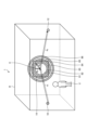
The definition of the Fresnel zone according to the second embodiment will be explained. As shown in FIG. 10, consider a situation in which radio waves from thepower transmitting device 10 pass through the radio wave control board 14 and reach the power receiving device 12. In FIG. 10, the center point (geometric center point) of the radio wave control board 14 is defined as center point C. Let the straight line distance between the power transmission device 10 and the center point C be d1 . Let the straight line distance between the power receiving device 12 and the center point C be d2 . Consider a plane that passes through the center point C and is perpendicular to a straight line connecting the power transmitting device 10 and the power receiving device 12. Here, consider a circle whose radius is defined by the following equation (1) on a plane, centering on the center point C.
第2実施形態に係るフレネルゾーンの定義について説明する。図10に示すように、送電装置10からの電波が、電波制御板14を通過して、受電装置12に到達する状況を考える。図10において、電波制御板14の中心点(幾何中心点)を中心点Cとする。送電装置10と、中心点Cとの間の直線距離をd1とする。受電装置12と、中心点Cとの間の直線距離をd2する。中心点Cを通り、送電装置10と受電装置12とを結ぶ直線に垂直な平面を考える。ここで、平面上において、中心点Cを中心として、半径が以下の式(1)で定義される円を考える。 (Fresnel zone)
The definition of the Fresnel zone according to the second embodiment will be explained. As shown in FIG. 10, consider a situation in which radio waves from the

式(1)において、nは自然数、λは電波の波長である。
In formula (1), n is a natural number and λ is the wavelength of the radio wave.
本実施形態では、式(1)において、半径Rn-1から半径Rnの範囲の円環部を第nフレネルゾーンと定義する。図10に示す例では、第1フレネルゾーン81と、第2フレネルゾーン82と、第3フレネルゾーン83と、第4フレネルゾーン84と、第5フレネルゾーン85と、第6フレネルゾーン86と、が示されている。例えば、半径R1の円の範囲が第1フレネルゾーン81となる。例えば、半径R1の円と、半径R2の円との間の円環部の範囲が第2フレネルゾーン82となる。
In this embodiment, in equation (1), the annular portion in the range from radius Rn-1 to radius Rn is defined as the n-th Fresnel zone. In the example shown in FIG. 10, a first Fresnel zone 81, a second Fresnel zone 82, a third Fresnel zone 83, a fourth Fresnel zone 84, a fifth Fresnel zone 85, and a sixth Fresnel zone 86 are It is shown. For example, the range of a circle with radius R1 becomes the first Fresnel zone 81. For example, the range of the annular portion between the circle with radius R1 and the circle with radius R2 becomes the second Fresnel zone 82.
本実施形態では、電波制御板14のサイズを、第1フレネルゾーン81の半径の2倍以上に設定する。第nフレネルゾーンの半径は、第nフレネル半径とも呼ばれる。本実施形態では、電波制御板14のサイズを第1フレネル半径の2倍以上に設定することで、効果的なワイヤレス電力伝送が可能となる。本実施形態では、電波制御板14のサイズは、第1フレネル半径の2倍の±25%の範囲に設定してもよい。
In this embodiment, the size of the radio wave control board 14 is set to be at least twice the radius of the first Fresnel zone 81. The radius of the nth Fresnel zone is also called the nth Fresnel radius. In this embodiment, by setting the size of the radio wave control board 14 to be twice or more the first Fresnel radius, effective wireless power transmission is possible. In this embodiment, the size of the radio wave control board 14 may be set within a range of ±25% of twice the first Fresnel radius.
本実施形態では、ユーザUと、受電装置12との距離が近い場合には、電波制御板14からの電波がユーザUに照射されてしまう可能性がある。そのため、本実施形態では、電波制御板14に含まれる各単位素子の位相変化量を制御することで、電波制御板14からの電波のビーム幅を狭くすることで、ユーザUに電波が照射されてしまうことを防止する。
In this embodiment, if the distance between the user U and the power receiving device 12 is short, there is a possibility that the user U will be irradiated with radio waves from the radio wave control board 14. Therefore, in this embodiment, by controlling the amount of phase change of each unit element included in the radio wave control board 14, the beam width of the radio waves from the radio wave control board 14 is narrowed, and the radio waves are irradiated to the user U. Prevent this from happening.
制御装置60は、例えば、送電装置10と電波制御板14との間の位相と、電波制御板14と受電装置12との間の位相とが一致するように、電波制御板14に含まれる各単位素子を制御する。制御装置60は、例えば、電波制御板14に含まれる各単位素子の位相変化量が同心円状に変化するように各単位素子の位相変化量を制御する。
For example, the control device 60 controls each component included in the radio wave control board 14 so that the phase between the power transmission device 10 and the radio wave control board 14 matches the phase between the radio wave control board 14 and the power receiving device 12. Control unit elements. For example, the control device 60 controls the amount of phase change of each unit element included in the radio wave control board 14 so that the amount of phase change of each unit element changes concentrically.
制御装置60は、電波制御板14に含まれる各単位素子のうち、偶数次フレネルゾーンに位置する単位素子のみを制御してもよい。または、制御装置60は、偶数次フレネルゾーンに位置する単位素子と、奇数次フレネルゾーンに位置する単位素子の位相を180°ずれるように制御してもよい。本実施形態では、偶数次フレネルゾーンに位置する単位素子のみを制御したもの、または数次フレネルゾーンに位置する単位素子と、奇数次フレネルゾーンに位置する単位素子の位相を180°ずれるようにしたものをフレネルゾーンプレートと呼ぶ。本実施形態では、電波制御板14に含まれる各単位素子をフレネルゾーンプレートとすることで、電波のビーム幅を狭くして、ユーザUに電波が照射されないように制御することができる。
The control device 60 may control only the unit elements located in the even-numbered Fresnel zone among the unit elements included in the radio wave control board 14. Alternatively, the control device 60 may control the unit elements located in the even Fresnel zone and the unit elements located in the odd Fresnel zone to be out of phase by 180 degrees. In this embodiment, only the unit elements located in the even-order Fresnel zone are controlled, or the phases of the unit elements located in the multi-order Fresnel zone and the unit elements located in the odd-order Fresnel zone are shifted by 180 degrees. This is called a Fresnel zone plate. In this embodiment, each unit element included in the radio wave control board 14 is a Fresnel zone plate, so that the beam width of the radio waves can be narrowed and control can be performed so that the user U is not irradiated with the radio waves.
[第3実施形態]
図11と、図12とを用いて、第3実施形態に係る電力伝送方法について説明する。図11と、図12とは、第3実施形態に係る電力伝送方法を説明するための図である。 [Third embodiment]
A power transmission method according to the third embodiment will be described using FIG. 11 and FIG. 12. FIG. 11 and FIG. 12 are diagrams for explaining the power transmission method according to the third embodiment.
図11に示すように、電力伝送システム1が設置されている空間R内に、ユーザU1と、ユーザU2とが位置している状況を考える。この場合、送電装置10は、ユーザU1に電波W1が照射されないように、電波制御板14に向けて電波W1を送電し、受電装置12は、電波制御板14から反射電波W2を受電する。しかしながら、この場合、電波W1のビーム幅が広い場合等には、電波制御板14をはみ出して壁などで反射した電波W1がユーザU2に照射されてしまう可能性がある。
As shown in FIG. 11, consider a situation where a user U1 and a user U2 are located in a space R in which the power transmission system 1 is installed. In this case, the power transmitting device 10 transmits the radio wave W1 toward the radio wave control board 14 so that the user U1 is not irradiated with the radio wave W1, and the power receiving device 12 receives the reflected radio wave W2 from the radio wave control board 14. However, in this case, if the beam width of the radio wave W1 is wide, the user U2 may be irradiated with the radio wave W1 that protrudes from the radio wave control board 14 and is reflected by a wall or the like.
そこで、第3実施形態では、図12に示すように、送電装置10は、電波W1のビーム幅を電波制御板14よりも狭くして電波W1が電波制御板14からはみ出してしまうことを防止する。具体的には、電波送電部30は、記憶部22に記憶されている電波制御板14のサイズを参照し、電波制御板14のサイズよりも電波W1のビーム幅を狭くなるように制御する。これにより、第3実施形態は、電波制御板14をはみ出して壁などで反射した電波W1がユーザU2に照射されてしまうことを防止することができる。
Therefore, in the third embodiment, as shown in FIG. 12, the power transmission device 10 makes the beam width of the radio wave W1 narrower than the radio wave control board 14 to prevent the radio wave W1 from protruding from the radio wave control board 14. . Specifically, the radio wave power transmission unit 30 refers to the size of the radio wave control board 14 stored in the storage unit 22 and controls the beam width of the radio wave W1 to be narrower than the size of the radio wave control board 14. Thereby, the third embodiment can prevent the user U2 from being irradiated with the radio wave W1 that protrudes from the radio wave control board 14 and is reflected by a wall or the like.
送電装置10は、電波W1が電波制御板14からはみ出したことを検出した場合に、電波W1のビーム幅を狭くしてもよい。この場合、例えば、電波制御板14の制御装置60が、電波制御板14が送電装置10から受けている電波W1の電力が予め定められた閾値よりも小さい場合に、電波W1が電波制御板14からはみ出していると判定するとよい。制御装置60は、例えば、電波W1が電波制御板14からはみ出していると判定した場合には、電波W1が電波制御板14からはみ出していることを示す情報を送信する。これにより、送電装置10は、電波W1が電波制御板14からはみ出したことを検出することができる。
The power transmission device 10 may narrow the beam width of the radio wave W1 when detecting that the radio wave W1 has protruded from the radio wave control board 14. In this case, for example, when the power of the radio wave W1 that the radio wave control board 14 receives from the power transmission device 10 is smaller than a predetermined threshold, the control device 60 of the radio wave control board 14 determines that the radio wave W1 is transmitted to the radio wave control board 14. It is best to judge that it is protruding from the outside. For example, when the control device 60 determines that the radio wave W1 is protruding from the radio wave control board 14, it transmits information indicating that the radio wave W1 is protruding from the radio wave control board 14. Thereby, the power transmission device 10 can detect that the radio wave W1 has protruded from the radio wave control board 14.
[第4実施形態]
図13と、図14とを用いて、第4実施形態に係る電力伝送方法について説明する。図13と、図14とは、第4実施形態に係る電力伝送方法を説明するための図である。 [Fourth embodiment]
A power transmission method according to the fourth embodiment will be described using FIG. 13 and FIG. 14. FIG. 13 and FIG. 14 are diagrams for explaining the power transmission method according to the fourth embodiment.
図13に示すように、電力伝送システム1が設置されている空間R内に、ユーザU1と、ユーザU2、ユーザU3とが位置している状況を考える。空間R内に位置するユーザの数が多くなると、いずれかのユーザ(例えば、ユーザU3)に電波W1が照射されてしまう可能性がある。
As shown in FIG. 13, consider a situation where a user U1, a user U2, and a user U3 are located in a space R in which the power transmission system 1 is installed. When the number of users located in the space R increases, there is a possibility that one of the users (for example, user U3) will be irradiated with the radio wave W1.
そこで、第4実施形態では、図14に示すように、空間R内に、電波制御板14-1および電波制御板14-2のように複数の電波制御板を設置する。この場合、送電装置10は、電波W1を電波制御板14-1に向けて送電する。電波制御板14-1は、電波W1を反射した反射電波W2を電波制御板14-2に送電する。電波制御板14-2は、反射電波W2を反射した反射電波W3を受電装置12に送電する。これにより、第4実施形態は、送電装置10から受電装置12の間において、人体に電波が照射されてしまうことを防止することができる。
Therefore, in the fourth embodiment, as shown in FIG. 14, a plurality of radio wave control boards are installed in the space R, such as the radio wave control board 14-1 and the radio wave control board 14-2. In this case, the power transmission device 10 transmits the radio wave W1 toward the radio wave control board 14-1. The radio wave control board 14-1 transmits a reflected radio wave W2 that has reflected the radio wave W1 to the radio wave control board 14-2. The radio wave control board 14-2 transmits the reflected radio wave W3, which is the reflected radio wave W2, to the power receiving device 12. Thereby, the fourth embodiment can prevent the human body from being irradiated with radio waves between the power transmitting device 10 and the power receiving device 12.
なお、図14に示す例では、空間R内には電波制御板14-1および電波制御板14-2の2枚の電波制御板が設置されているが、本開示はこれに限定されない。空間R内には、3枚以上の電波制御板が設置されていてもよい。空間R内に設置する電波制御板の数を増やすことで、送電装置10から受電装置12までの電波の伝送路の数を増やすことができる。なお、複数の電波制御板で反射が繰り返されることで損失が大きくなり、電波が送電装置10から受電装置12に到達するまでに電力が小さくなってしまうことも想定される。そのため、第4実施形態では、電力の減衰が許容できる範囲内において、空間R内に設置する電波制御板の数の上限を設定してもよい。
Note that in the example shown in FIG. 14, two radio wave control boards, the radio wave control board 14-1 and the radio wave control board 14-2, are installed in the space R, but the present disclosure is not limited thereto. Three or more radio wave control boards may be installed in the space R. By increasing the number of radio wave control boards installed in the space R, the number of radio wave transmission paths from the power transmitting device 10 to the power receiving device 12 can be increased. Note that it is also assumed that the loss increases due to repeated reflections by a plurality of radio wave control boards, and that the electric power becomes small by the time the radio waves reach the power receiving device 12 from the power transmitting device 10. Therefore, in the fourth embodiment, an upper limit on the number of radio wave control boards installed in the space R may be set within a range where power attenuation is allowable.
[第5実施形態]
図15と、図16とを用いて、第5実施形態に係る電力伝送方法について説明する。図15と、図16とは、第5実施形態に係る電力伝送方法を説明するための図である。 [Fifth embodiment]
The power transmission method according to the fifth embodiment will be described using FIG. 15 and FIG. 16. FIG. 15 and FIG. 16 are diagrams for explaining the power transmission method according to the fifth embodiment.
図15に示すように、電力伝送システム1が設置されている空間R内に、ユーザU1と、ユーザU2とが位置している状況を考える。図15に示す例では、送電装置10は、電波制御板14-1および電波制御板14-2に向けて電波W1を送電する。電波制御板14-1は、電波W1を反射した反射電波W2を受電装置12に送電する。電波制御板14-2は、電波W1を反射した反射電波W4を受電装置12に送電する。この際、ユーザU1が受電装置12と、電波制御板14-1とを結ぶ直線上に位置している場合には、ユーザU1に反射電波W2が照射されてしまう可能性があった。
As shown in FIG. 15, consider a situation where a user U1 and a user U2 are located in a space R in which the power transmission system 1 is installed. In the example shown in FIG. 15, the power transmission device 10 transmits the radio wave W1 toward the radio wave control board 14-1 and the radio wave control board 14-2. The radio wave control board 14-1 transmits a reflected radio wave W2 that reflects the radio wave W1 to the power receiving device 12. The radio wave control board 14-2 transmits a reflected radio wave W4 that reflects the radio wave W1 to the power receiving device 12. At this time, if the user U1 is located on a straight line connecting the power receiving device 12 and the radio wave control board 14-1, there is a possibility that the reflected radio wave W2 will be irradiated to the user U1.
そこで、第5実施形態では、図16に示すように、ユーザU1に反射した電波が照射されないように、電波W1を吸収するように電波制御板14-1の各単位素子を制御する。この場合、送電装置10の制御部24の位置検出部34は、受電装置12と、電波制御板14-1とを結ぶ直線上にユーザU1が位置していることを検出した場合には、ユーザU1の位置情報を含む情報を電波制御板14-1の制御装置60に送信する。そして、制御装置60は、ユーザU1の位置情報に基づいてユーザU1に電波が照射されないように、電波W1を吸収するように電波制御板14-1の各単位素子を制御する。これにより、第5実施形態は、送電装置10から受電装置12の間において、人体に電波が照射されてしまうことを防止することができる。
Therefore, in the fifth embodiment, as shown in FIG. 16, each unit element of the radio wave control board 14-1 is controlled to absorb the radio wave W1 so that the user U1 is not irradiated with the reflected radio wave. In this case, when the position detection unit 34 of the control unit 24 of the power transmission device 10 detects that the user U1 is located on the straight line connecting the power reception device 12 and the radio wave control board 14-1, the position detection unit 34 of the control unit 24 of the power transmission device 10 detects that the user Information including the position information of U1 is transmitted to the control device 60 of the radio wave control board 14-1. Then, the control device 60 controls each unit element of the radio wave control board 14-1 to absorb the radio wave W1 so that the user U1 is not irradiated with the radio wave based on the position information of the user U1. Thereby, the fifth embodiment can prevent the human body from being irradiated with radio waves between the power transmitting device 10 and the power receiving device 12.
以上、本開示の実施形態を説明したが、これら実施形態の内容により本開示が限定されるものではない。また、前述した構成要素には、当業者が容易に想定できるもの、実質的に同一のもの、いわゆる均等の範囲のものが含まれる。さらに、前述した構成要素は適宜組み合わせることが可能である。さらに、前述した実施形態の要旨を逸脱しない範囲で構成要素の種々の省略、置換又は変更を行うことができる。
Although the embodiments of the present disclosure have been described above, the present disclosure is not limited by the contents of these embodiments. Furthermore, the above-mentioned components include those that can be easily assumed by those skilled in the art, those that are substantially the same, and those that are in a so-called equivalent range. Furthermore, the aforementioned components can be combined as appropriate. Furthermore, various omissions, substitutions, or modifications of the constituent elements can be made without departing from the gist of the embodiments described above.
1 電力伝送システム
10 送電装置
12 受電装置
14 電波制御板
20,40 アンテナ部
22,42 記憶部
24,44 制御部
30 電波送電部
32 信号受信部
34 位置検出部
50 電波受電部
52 信号送信部 1Power transmission system 10 Power transmission device 12 Power reception device 14 Radio wave control board 20, 40 Antenna section 22, 42 Storage section 24, 44 Control section 30 Radio wave power transmission section 32 Signal reception section 34 Position detection section 50 Radio wave reception section 52 Signal transmission section
10 送電装置
12 受電装置
14 電波制御板
20,40 アンテナ部
22,42 記憶部
24,44 制御部
30 電波送電部
32 信号受信部
34 位置検出部
50 電波受電部
52 信号送信部 1
Claims (13)
- 電波を送電する送電装置と、
前記電波を受電する受電装置と、
前記送電装置が送電した前記電波を受けて、前記電波の伝送方向を前記受電装置に向けて変化させる電波制御板と、
を含む、電力伝送システム。 A power transmission device that transmits radio waves,
a power receiving device that receives the radio waves;
a radio wave control board that receives the radio waves transmitted by the power transmission device and changes the transmission direction of the radio waves toward the power reception device;
including power transmission systems. - 前記送電装置と、前記受電装置と、前記電波制御板とを制御する制御装置とを含み、
前記制御装置は、前記受電装置から送信されるパイロット信号に基づいて、前記電波制御板からの前記電波の出射角度を前記受電装置において最大電力が得られる角度に設定する、
請求項1に記載の電力伝送システム。 A control device that controls the power transmission device, the power reception device, and the radio control board,
The control device sets an emission angle of the radio waves from the radio wave control board to an angle at which maximum power is obtained in the power receiving device, based on a pilot signal transmitted from the power receiving device.
The power transmission system according to claim 1. - 前記電波制御板のサイズは、第1フレネル半径の2倍以上である、
請求項1または2に記載の電力伝送システム。 The size of the radio wave control board is at least twice the first Fresnel radius,
The power transmission system according to claim 1 or 2. - 前記電波制御板は、それぞれ透過位相の異なる複数の素子を備え、
前記制御装置は、複数の前記素子を制御して、前記電波制御板から出射される電波のビーム幅を狭くする、
請求項2に記載の電力伝送システム。 The radio wave control board includes a plurality of elements each having a different transmission phase,
The control device controls the plurality of elements to narrow the beam width of radio waves emitted from the radio wave control board.
The power transmission system according to claim 2. - 前記制御装置は、位相変化量が同心円状に変化するように複数の前記素子を制御する、
請求項4に記載の電力伝送システム。 The control device controls the plurality of elements so that the amount of phase change changes concentrically.
The power transmission system according to claim 4. - 前記制御装置は、位相変化量が受電装置のアンテナ位置で位相が一致するように複数の前記素子を制御する、
請求項5に記載の電力伝送システム。 The control device controls the plurality of elements so that the amount of phase change matches the phase at the antenna position of the power receiving device.
The power transmission system according to claim 5. - 前記送電装置と前記電波制御板の幾何中心との間の直線距離をd1、前記電波制御板の幾何中心との間の直線距離をd2としたとき、前記電波制御板の幾何中心を中心として、半径が以下の式(1)で定義される円を考え、

半径Rn-1から半径Rnの範囲の円環部を第nフレネルゾーンと定義したとき、
前記制御装置は、偶数次フレネルゾーンに位置する前記素子のみを前記電波の伝送方向を制御し、または前記偶数次フレネルゾーンに位置する前記素子と、奇数次フレネルゾーンに位置する前記素子の位相を180°ずれるように制御する、
請求項4に記載の電力伝送システム。 When the straight line distance between the power transmission device and the geometric center of the radio wave control board is d1 , and the straight line distance between the geometric center of the radio wave control board is d2 , the center is the geometric center of the radio wave control board. Considering a circle whose radius is defined by the following equation (1),
When the annular part in the range from radius Rn-1 to radius Rn is defined as the n-th Fresnel zone,
The control device controls the transmission direction of the radio waves only for the element located in an even-numbered Fresnel zone, or controls the phase of the element located in the even-numbered Fresnel zone and the element located in an odd-numbered Fresnel zone. Control to shift by 180°,
The power transmission system according to claim 4. - 前記制御装置は、前記送電装置が送電する前記電波のビーム幅を、前記電波制御板のサイズよりも狭くする、
請求項2に記載の電力伝送システム。 The control device makes the beam width of the radio waves transmitted by the power transmission device narrower than the size of the radio wave control board.
The power transmission system according to claim 2. - 前記制御装置は、前記送電装置が送電する前記電波が前記電波制御板からはみ出している場合に、前記送電装置が送電する前記電波のビーム幅を、前記電波制御板のサイズよりも狭くする、
請求項8に記載の電力伝送システム。 The control device makes the beam width of the radio wave transmitted by the power transmission device narrower than the size of the radio wave control board when the radio wave transmitted by the power transmission device protrudes from the radio wave control board.
The power transmission system according to claim 8. - 前記電波制御板を複数含み、
前記制御装置は、複数の前記電波制御板を制御して、前記送電装置からの前記電波を複数の前記電波制御板を介して前記受電装置まで伝送する、
請求項2に記載の電力伝送システム。 including a plurality of the radio wave control boards;
The control device controls the plurality of radio wave control boards to transmit the radio waves from the power transmission device to the power receiving device via the plurality of radio wave control boards.
The power transmission system according to claim 2. - 前記制御装置は、前記電波制御板と、前記受電装置とを結ぶ直線状に動体が存在している場合には、複数の前記素子を制御して、前記電波制御板が前記電波を吸収するように制御する、
請求項4に記載の電力伝送システム。 The control device controls the plurality of elements so that the radio wave control board absorbs the radio waves when a moving object exists in a straight line connecting the radio wave control board and the power receiving device. to control,
The power transmission system according to claim 4. - 前記電波制御板は、整流器と、バッテリとを備え、
前記整流器は、前記電波制御板が吸収した前記電波を用いて前記バッテリを充電する、
請求項11に記載の電力伝送システム。 The radio wave control board includes a rectifier and a battery,
The rectifier charges the battery using the radio waves absorbed by the radio wave control board.
The power transmission system according to claim 11. - 送電装置から電波を送電させるステップと、
前記送電装置が送電した前記電波を受ける電波制御板を制御して、前記電波の伝送方向を受電装置に向けて変化させるステップ、
前記受電装置で前記電波を受信させるステップと、
を含む、電力伝送方法。 a step of transmitting radio waves from the power transmission device;
controlling a radio wave control board that receives the radio waves transmitted by the power transmitting device to change the transmission direction of the radio waves toward the power receiving device;
a step of causing the power receiving device to receive the radio waves;
including power transmission methods.
Applications Claiming Priority (2)
| Application Number | Priority Date | Filing Date | Title |
|---|---|---|---|
| JP2022084326 | 2022-05-24 | ||
| JP2022-084326 | 2022-05-24 |
Publications (1)
| Publication Number | Publication Date |
|---|---|
| WO2023228693A1 true WO2023228693A1 (en) | 2023-11-30 |
Family
ID=88919013
Family Applications (1)
| Application Number | Title | Priority Date | Filing Date |
|---|---|---|---|
| PCT/JP2023/017095 WO2023228693A1 (en) | 2022-05-24 | 2023-05-01 | Power transmission system and power transmission method |
Country Status (1)
| Country | Link |
|---|---|
| WO (1) | WO2023228693A1 (en) |
Citations (5)
| Publication number | Priority date | Publication date | Assignee | Title |
|---|---|---|---|---|
| US20180198320A1 (en) * | 2017-01-12 | 2018-07-12 | David R. Criswell | System and method for transmitting and receiving power wirelessly |
| US20190372399A1 (en) * | 2016-09-19 | 2019-12-05 | Samsung Electronics Co., Ltd. | Wireless power transmitter and control method therefor |
| CN110635582A (en) * | 2019-08-30 | 2019-12-31 | 同济大学 | Wireless energy transmission system and method for exciting and amplifying electromagnetic echo |
| WO2021199504A1 (en) * | 2020-03-31 | 2021-10-07 | Agc株式会社 | Wireless transmission system |
| WO2022091660A1 (en) * | 2020-10-28 | 2022-05-05 | 住友電気工業株式会社 | Reflection unit and wireless transmission system |
-
2023
- 2023-05-01 WO PCT/JP2023/017095 patent/WO2023228693A1/en unknown
Patent Citations (5)
| Publication number | Priority date | Publication date | Assignee | Title |
|---|---|---|---|---|
| US20190372399A1 (en) * | 2016-09-19 | 2019-12-05 | Samsung Electronics Co., Ltd. | Wireless power transmitter and control method therefor |
| US20180198320A1 (en) * | 2017-01-12 | 2018-07-12 | David R. Criswell | System and method for transmitting and receiving power wirelessly |
| CN110635582A (en) * | 2019-08-30 | 2019-12-31 | 同济大学 | Wireless energy transmission system and method for exciting and amplifying electromagnetic echo |
| WO2021199504A1 (en) * | 2020-03-31 | 2021-10-07 | Agc株式会社 | Wireless transmission system |
| WO2022091660A1 (en) * | 2020-10-28 | 2022-05-05 | 住友電気工業株式会社 | Reflection unit and wireless transmission system |
Similar Documents
| Publication | Publication Date | Title |
|---|---|---|
| US8643536B2 (en) | Radio frequency positioning system for vehicles | |
| US7142147B2 (en) | Method and apparatus for detecting, locating, and identifying microwave transmitters and receivers at distant locations | |
| JP2006153878A (en) | Intruder detecting device and radiowave reflector | |
| US20070070358A1 (en) | Object information sensing apparatus, pointing device, and interface system | |
| JP2011257350A (en) | Radar device | |
| JP7211398B2 (en) | waveguide slot antenna | |
| JP4773759B2 (en) | Obstacle detection radar system | |
| JPH09191213A (en) | Opening surface antenna | |
| US11056766B2 (en) | Antenna apparatus | |
| JP2006242844A (en) | Radar apparatus and transmitted beam controlling technique | |
| WO2023228693A1 (en) | Power transmission system and power transmission method | |
| TW202224268A (en) | Reflection unit and wireless transmission system | |
| US20230088273A1 (en) | Power supply system, power supply device, and power supply method | |
| JPWO2022091660A5 (en) | ||
| JP3778056B2 (en) | Intruder detection device | |
| US20120235850A1 (en) | Mobile object detecting apparatus | |
| JP2006133108A (en) | Radar system, object detection method, radar device and radio reflector | |
| CN216434361U (en) | Distance measuring system | |
| WO2019159802A1 (en) | Control device, irradiation system, control method, and program | |
| JPH09304517A (en) | Millimeter-wave imaging radar | |
| JP2007240184A (en) | Radar device | |
| CN114578380A (en) | Detection device, control method and control device thereof, laser radar system and terminal | |
| JP2013070366A (en) | Aerial wire | |
| CN112313531A (en) | Distance measuring device and control method for scanning view field thereof | |
| JP2835705B2 (en) | Object detection method by microwave |
Legal Events
| Date | Code | Title | Description |
|---|---|---|---|
| 121 | Ep: the epo has been informed by wipo that ep was designated in this application |
Ref document number: 23811571 Country of ref document: EP Kind code of ref document: A1 |