WO2023228548A1 - ビーム整形装置、および加工装置 - Google Patents
ビーム整形装置、および加工装置 Download PDFInfo
- Publication number
- WO2023228548A1 WO2023228548A1 PCT/JP2023/012269 JP2023012269W WO2023228548A1 WO 2023228548 A1 WO2023228548 A1 WO 2023228548A1 JP 2023012269 W JP2023012269 W JP 2023012269W WO 2023228548 A1 WO2023228548 A1 WO 2023228548A1
- Authority
- WO
- WIPO (PCT)
- Prior art keywords
- light modulator
- spatial light
- pattern
- focal length
- beam shaping
- Prior art date
Links
- 238000007493 shaping process Methods 0.000 title claims abstract description 126
- 238000012545 processing Methods 0.000 title claims description 44
- 230000003287 optical effect Effects 0.000 claims abstract description 54
- 239000004973 liquid crystal related substance Substances 0.000 claims description 30
- 230000004075 alteration Effects 0.000 claims description 14
- 239000000463 material Substances 0.000 claims description 14
- 238000012937 correction Methods 0.000 claims description 9
- 239000007788 liquid Substances 0.000 claims description 5
- 230000004048 modification Effects 0.000 description 66
- 238000012986 modification Methods 0.000 description 66
- 238000010586 diagram Methods 0.000 description 24
- 238000000034 method Methods 0.000 description 21
- 238000003754 machining Methods 0.000 description 18
- 230000007423 decrease Effects 0.000 description 13
- 230000008569 process Effects 0.000 description 8
- 230000000052 comparative effect Effects 0.000 description 7
- 238000009826 distribution Methods 0.000 description 6
- 230000000694 effects Effects 0.000 description 6
- 230000008859 change Effects 0.000 description 5
- 238000005516 engineering process Methods 0.000 description 4
- 238000003672 processing method Methods 0.000 description 4
- 230000001678 irradiating effect Effects 0.000 description 3
- 238000005476 soldering Methods 0.000 description 3
- 235000012431 wafers Nutrition 0.000 description 3
- 230000000295 complement effect Effects 0.000 description 2
- 238000013461 design Methods 0.000 description 2
- 230000005684 electric field Effects 0.000 description 2
- 239000004986 Cholesteric liquid crystals (ChLC) Substances 0.000 description 1
- XUIMIQQOPSSXEZ-UHFFFAOYSA-N Silicon Chemical compound [Si] XUIMIQQOPSSXEZ-UHFFFAOYSA-N 0.000 description 1
- 230000008901 benefit Effects 0.000 description 1
- 230000000670 limiting effect Effects 0.000 description 1
- 230000001151 other effect Effects 0.000 description 1
- 238000004904 shortening Methods 0.000 description 1
- 229910052710 silicon Inorganic materials 0.000 description 1
- 239000010703 silicon Substances 0.000 description 1
- 238000003466 welding Methods 0.000 description 1
Images


Classifications
-
- B—PERFORMING OPERATIONS; TRANSPORTING
- B23—MACHINE TOOLS; METAL-WORKING NOT OTHERWISE PROVIDED FOR
- B23K—SOLDERING OR UNSOLDERING; WELDING; CLADDING OR PLATING BY SOLDERING OR WELDING; CUTTING BY APPLYING HEAT LOCALLY, e.g. FLAME CUTTING; WORKING BY LASER BEAM
- B23K26/00—Working by laser beam, e.g. welding, cutting or boring
- B23K26/02—Positioning or observing the workpiece, e.g. with respect to the point of impact; Aligning, aiming or focusing the laser beam
- B23K26/06—Shaping the laser beam, e.g. by masks or multi-focusing
- B23K26/064—Shaping the laser beam, e.g. by masks or multi-focusing by means of optical elements, e.g. lenses, mirrors or prisms
-
- B—PERFORMING OPERATIONS; TRANSPORTING
- B23—MACHINE TOOLS; METAL-WORKING NOT OTHERWISE PROVIDED FOR
- B23K—SOLDERING OR UNSOLDERING; WELDING; CLADDING OR PLATING BY SOLDERING OR WELDING; CUTTING BY APPLYING HEAT LOCALLY, e.g. FLAME CUTTING; WORKING BY LASER BEAM
- B23K26/00—Working by laser beam, e.g. welding, cutting or boring
- B23K26/08—Devices involving relative movement between laser beam and workpiece
-
- G—PHYSICS
- G02—OPTICS
- G02B—OPTICAL ELEMENTS, SYSTEMS OR APPARATUS
- G02B27/00—Optical systems or apparatus not provided for by any of the groups G02B1/00 - G02B26/00, G02B30/00
- G02B27/09—Beam shaping, e.g. changing the cross-sectional area, not otherwise provided for
-
- G—PHYSICS
- G02—OPTICS
- G02F—OPTICAL DEVICES OR ARRANGEMENTS FOR THE CONTROL OF LIGHT BY MODIFICATION OF THE OPTICAL PROPERTIES OF THE MEDIA OF THE ELEMENTS INVOLVED THEREIN; NON-LINEAR OPTICS; FREQUENCY-CHANGING OF LIGHT; OPTICAL LOGIC ELEMENTS; OPTICAL ANALOGUE/DIGITAL CONVERTERS
- G02F1/00—Devices or arrangements for the control of the intensity, colour, phase, polarisation or direction of light arriving from an independent light source, e.g. switching, gating or modulating; Non-linear optics
- G02F1/01—Devices or arrangements for the control of the intensity, colour, phase, polarisation or direction of light arriving from an independent light source, e.g. switching, gating or modulating; Non-linear optics for the control of the intensity, phase, polarisation or colour
- G02F1/13—Devices or arrangements for the control of the intensity, colour, phase, polarisation or direction of light arriving from an independent light source, e.g. switching, gating or modulating; Non-linear optics for the control of the intensity, phase, polarisation or colour based on liquid crystals, e.g. single liquid crystal display cells
Definitions
- the present disclosure relates to a beam shaping device and a processing device that use a phase modulation spatial light modulator (SLM).
- SLM phase modulation spatial light modulator
- a method using a phase modulation spatial light modulator has been proposed (see, for example, Patent Documents 1 and 2).
- a spatial light modulator displays a phase pattern that corresponds to an irradiation pattern applied to an object to be processed. It has also been proposed to have the ability to adjust the position in the depth direction (vertical direction) of irradiating the irradiation pattern by superimposing a phase distribution that provides a lens function as the phase pattern displayed on the spatial light modulator. .
- a beam shaping device includes a phase modulation spatial light modulator that displays a phase pattern according to an irradiation pattern irradiated onto a target object, and a beam shaping device that targets light modulated by the spatial light modulator. and an optical device with a variable focal length that focuses light onto an object.
- a processing apparatus includes a phase modulation spatial light modulator that displays a phase pattern according to an irradiation pattern irradiated onto an object to be processed, and light modulated by the spatial light modulator. and an optical device with a variable focal length that focuses the light toward the object.
- a spatial light modulator displays a phase pattern according to an irradiation pattern irradiating a target object, and an optical device with a variable focal length displays The light modulated by the spatial light modulator is focused toward the target.
- FIG. 1 is an explanatory diagram showing an overview of dielectric anisotropy of liquid crystal.
- FIG. 2 is an explanatory diagram showing an overview of the refractive index anisotropy of liquid crystal.
- FIG. 3 is a configuration diagram showing an outline of a phase modulation type spatial light modulator.
- FIG. 4 is a configuration diagram schematically showing a first configuration example of a beam shaping device according to a comparative example.
- FIG. 5 is a configuration diagram schematically showing a second configuration example of a beam shaping device according to a comparative example.
- FIG. 6 is a configuration diagram schematically showing a configuration example of a beam shaping device according to an embodiment of the present disclosure.
- FIG. 7 is an explanatory diagram schematically showing the effect of a variable focus lens in a beam shaping device according to an embodiment.
- FIG. 8 is an explanatory diagram schematically showing an example of a processing method using a beam shaping device according to an embodiment.
- FIG. 9 is an explanatory diagram schematically showing an example of a processing method using a beam shaping device according to an embodiment.
- FIG. 10 is a configuration diagram schematically showing a configuration example of a beam shaping device according to Modification 1.
- FIG. 11 is a configuration diagram schematically showing a configuration example of a beam shaping device according to a second modification.
- FIG. 12 is a configuration diagram schematically showing a configuration example of a beam shaping device according to modification 3.
- FIG. 13 is a configuration diagram schematically showing a configuration example of a beam shaping device according to modification 4.
- FIG. 14 is a configuration diagram schematically showing a configuration example of a beam shaping device according to modification 5.
- FIG. 15 is a configuration diagram schematically showing a configuration example of a beam shaping device according to modification 6.
- FIG. 16 is a configuration diagram schematically showing a configuration example of a beam shaping device according to Modification Example 7.
- FIG. 17 is a configuration diagram schematically showing a first configuration example of a beam shaping device according to modification 8.
- FIG. 18 is a configuration diagram schematically showing a second configuration example of a beam shaping device according to modification example 8.
- FIG. 19 is a configuration diagram schematically showing a configuration example of a beam shaping device according to modification 9.
- FIG. 19 is a configuration diagram schematically showing a configuration example of a beam shaping device according to modification 9.
- FIG. 20 is a configuration diagram schematically showing a configuration example of a beam shaping device according to modification 10.
- FIG. 21 is a configuration diagram schematically showing a configuration example of a beam shaping device according to Modification Example 11.
- FIG. 22 is a configuration diagram schematically showing a configuration example of a beam shaping device according to modification 12.
- FIG. 23 is a configuration diagram schematically showing a configuration example of a beam shaping device according to modification 13.
- FIG. 24 is a configuration diagram schematically showing an example of application of a beam shaping device according to an embodiment to a processing device.
- FIG. 1 shows an overview of the dielectric anisotropy of liquid crystals.
- FIG. 2 shows an overview of the refractive index anisotropy of liquid crystal.
- FIG. 3 shows an overview of a phase modulation spatial light modulator.
- Liquid crystal has dielectric anisotropy. As shown in FIG. 1, when an electric field E is applied to a liquid crystal molecule 100, the long axis is parallel to the electric field direction as positive dielectric anisotropy, and the short axis is parallel as negative dielectric anisotropy. It's called sex. Further, the liquid crystal has refractive index anisotropy, in which the refractive index differs depending on the direction of the liquid crystal molecules 100. As shown in FIG.
- a phase modulation spatial light modulator is a device that modulates only the phase of light by utilizing the properties of liquid crystal described above.
- FIG. 3 shows an example of the configuration of a reflective spatial light modulator.
- the spatial light modulator has a structure in which a liquid crystal layer containing liquid crystal molecules 100 is sandwiched between a common electrode 111 and a pixel electrode 121 that are arranged to face each other.
- the common electrode 111 is a transparent electrode, and an alignment film is formed on the surface facing the liquid crystal layer.
- a reflective film and an alignment film are formed on the surface of the pixel electrode 121 on the liquid crystal layer side.
- a pretilt angle is given to the liquid crystal molecules 100, and when no voltage is applied between the common electrode 111 and the pixel electrode 121 (voltage OFF), the liquid crystal molecules 100 are in a standing state at the pretilt angle. Become. By applying a voltage (voltage ON) between the common electrode 111 and the pixel electrode 121, the liquid crystal molecules 100 fall down. Therefore, the state of the liquid crystal molecules 100 when the light passes is different between the reflected light L21 from the pixel electrode 121 with the voltage OFF and the reflected light L22 from the pixel electrode 121 with the voltage ON. , a phase difference occurs between them. Thereby, in the spatial light modulator, by controlling the voltage applied to the liquid crystal layer, it is possible to control the phase of the incident light L1 in an analog manner.
- FIG. 4 schematically shows a first configuration example of a beam shaping device according to a comparative example.
- FIG. 5 schematically shows a second configuration example of a beam shaping device according to a comparative example.
- phase modulation spatial light modulators in the fields of beam shaping and processing machines.
- FIG. 10 There is a method of irradiating the irradiated surface 50 (object to be processed, etc.) as a pattern.
- the spatial light modulator 10 displays, as a display pattern, a phase pattern that corresponds to the irradiation pattern that irradiates the object.
- a focused spot point P1 is formed on the irradiated surface 50 using only the spatial light modulator 10.
- the phase pattern displayed on the spatial light modulator 10 becomes complex and the diffraction efficiency is low.
- the focused spot point P1 is applied to the irradiated surface 50 via the Fourier transform lens 20 with a fixed focal length.
- the in-plane position (distance x from the center of the irradiation area) and two-dimensional distribution of the focused spot point P1 are controlled by the spatial light modulator 10.
- the phase pattern displayed on the spatial light modulator 10 is complicated and the diffraction efficiency is low.
- the second method collects light using the focusing power of the Fourier transform lens 20, so it has the advantage of being able to efficiently collect light into a minute spot. If the light spot shifts, the phase pattern becomes complicated and the diffraction efficiency decreases.
- the spatial light modulator 10 is utilized in dicing silicon wafers.
- a modified layer is formed by focusing laser light inside the wafer, and then the wafer is cut.
- the spatial light modulator 10 plays a role in correcting aberrations occurring in the base material.
- processing using the current spatial light modulator 10 is limited to forming a simple focal point, so in the second method, the focal point of the Fourier transform lens 20 is The focal length f may be such that the spot size can be obtained.
- the spatial light modulator 10 can form an arbitrary two-dimensional distribution of light, it can be expected to realize processing and welding of more complex shapes.
- a complex shape refers to machining in which machining points are distributed in the depth direction or in which various sizes are mixed.
- the minimum spot size and irradiation range are fixed, making it difficult to meet diversifying needs for irradiation shapes.
- the position of the focal spot point P1 in the depth direction is fixed to the focal length f (FIG. 5). It is also possible to move the focal spot point P1 before and after the focal length f by superimposing a lens-shaped phase pattern such as a Fresnel lens pattern on the spatial light modulator 10, but the spatial light modulation increases as the distance from the focal plane increases. Since the Fresnel lens pattern displayed on the instrument 10 becomes finer, the diffraction efficiency decreases.
- Patent Document 1 Japanese Unexamined Patent Publication No. 2006-119427 discloses that when phase modulating light emitted from a laser light source using a phase modulation type spatial light modulator, a phase distribution for position movement is added to input data. A superimposed laser processing method has been proposed.
- Patent Document 2 Japanese Unexamined Patent Publication No. 2016-75810 discloses that Bessel light is generated by superimposing a phase distribution for moving a focal point on a phase distribution that forms Bessel light on a spatial light modulator. It has been proposed to move the irradiation position.
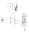
- FIG. 6 schematically shows a configuration example of a beam shaping device according to an embodiment of the present disclosure.
- a beam shaping device includes a phase modulation spatial light modulator 10 and a variable focus lens 21 as an optical device with a variable focal length f.
- the spatial light modulator 10 modulates the phase of the incident light L10 to display, as a display pattern, a phase pattern corresponding to the irradiation pattern irradiated onto the irradiation surface 50 (the surface to be processed, the object to be processed, etc.). .
- the spatial light modulator 10 forms, as an irradiation pattern, a hologram that forms one or more focused spot points P1 on the irradiated surface 50, for example.
- Light from a light source 30 having a certain degree of coherency enters the spatial light modulator 10 as incident light L10.
- the light source 30 may be a laser light source, or an LED (Light Emitting Diode) having a certain degree of spatial coherency.
- the spatial light modulator 10 can modulate the phase of the light from the light source 30, form an arbitrary shape by interference of the light, and modulate the direction in which the light travels.
- Spatial light modulator 10 has a two-dimensional pixel array.
- the spatial light modulator 10 may be of a reflective type or a transmissive type.
- the variable focus lens 21 focuses the light modulated by the spatial light modulator 10 toward the object, and forms a focused spot point P1 on the irradiated surface 50.
- the variable focus lens 21 may be a liquid crystal lens 22, a revolver type variable focus lens 24, a liquid lens 25, etc., as shown in modified examples (FIGS. 20 to 23) to be described later. Further, a phase modulation type spatial light modulator 23 may be provided separately from the spatial light modulator 10 that forms the irradiation pattern.
- the spatial frequency of the phase pattern displayed on the spatial light modulator 10 increases, the diffraction efficiency decreases.
- the spatial frequency of the phase pattern displayed on the spatial light modulator 10 is reduced, and a decrease in diffraction efficiency is suppressed. do.
- the spatial frequency of the phase pattern displayed on the spatial light modulator 10 can be reduced by leaving focus movement in the depth direction to the variable focus lens 21. Since the focus can be modulated by the variable focus lens 21, it is possible to control the combination of the range in which the condensed spot point P1 can be formed and the resolution.
- the focal plane is shifted by replacing the Fourier transform lens 20 with a fixed focal length with a variable focal length lens 21, compared to the configuration of the beam shaping device according to the comparative example (FIG. 5).
- This function can be realized by the variable focus lens 21.
- FIG. 7 schematically shows the effect of the variable focus lens 21 in the beam shaping device according to one embodiment.
- the focal length f can be modulated by the variable focus lens 21, it becomes possible to change the resolution of laser shaping and the range in which light can be irradiated.
- ⁇ is the wavelength of the incident light L10. The smaller the focal length f, the larger the NA becomes, so the spot diameter can be made smaller.
- x max f ⁇ tan ⁇ max
- ⁇ max is the maximum diffraction angle of the spatial light modulator 10. From this equation, it can be seen that the longer the focal length f, the larger the range that can be irradiated.
- the functions of the variable focus lens 21 from the viewpoint of processing applications include a function of modulating the position in the depth direction where a processing pattern is formed, and a function of modulating the size and resolution of the processing pattern.
- the processing proceeds while changing the focal length f of the variable focus lens 21 during the processing.
- the driving speed of the variable focus lens 21 is slower than the driving speed of the spatial light modulator 10. Therefore, by reducing the number of times the focal length f of the variable focus lens 21 is switched, it is possible to maximize the processing throughput.
- FIGS. 8 and 9 schematically show an example of a processing method using a beam shaping device according to an embodiment.
- throughput can be maximized by sequentially processing the machining points P2 at the same depth. That is, after processing all processing points P2 at a certain depth, the focal length f is sequentially changed and processing points P2 at different depths are sequentially processed, thereby changing the focal length of the variable focus lens 21. The number of times f is switched can be reduced and throughput can be maximized.
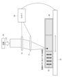
- FIG. 10 schematically shows a configuration example of a beam shaping device according to Modification 1.
- the focal position by the variable focus lens 21 is set in the vertical direction (depth direction) in a pattern (spot position control pattern) corresponding to the irradiation pattern. ) displays a pattern in which the focus movement pattern to be moved is superimposed.
- the spatial light modulator 10 superimposes a focus movement pattern to an extent that the diffraction efficiency does not decrease, thereby making it possible to shift the focus of the variable focus lens 21 in the depth direction. Furthermore, since the 0th order diffracted light on the irradiated surface 50 is defocused, it is possible to prevent the object from being processed at the focal point of the 0th order diffracted light. Further, for example, when the variable focus lens 21 is a revolver type variable focus lens 24 (FIG. 22), which will be described later, the variable focal length f becomes intermittently.
- the spatial light modulator 10 corresponds to the focal length f that is not included in the revolver type variable focus lens 24 as a phase pattern.
- FIG. 11 schematically shows a configuration example of a beam shaping device according to modification 2.
- a correction pattern for correcting aberrations caused by the variable focus lens 21 is added to the pattern corresponding to the irradiation pattern (spot position control pattern). Display the superimposed pattern.
- variable focus lens 21 has aberrations. If the aberration is known, by superimposing a correction pattern for correcting the aberration as a phase pattern, the aberration caused by the variable focus lens 21 can be canceled out by the correction pattern displayed on the spatial light modulator 10, It is possible to minimize the focused spot diameter. Thereby, it is possible to improve the resolution of the focused spot point P1.
- FIG. 12 schematically shows a configuration example of a beam shaping device according to modification 3.
- the base material of the irradiated surface 50 (object to be processed, etc.) is added to the pattern (spot position control pattern) corresponding to the irradiation pattern.
- a pattern in which a correction pattern for correcting aberrations caused by the image forming apparatus 40 is superimposed is displayed.
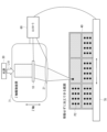
- FIG. 13 schematically shows a configuration example of a beam shaping device according to modification 4.
- the beam shaping device further includes a controller 60 that performs switching control of the phase pattern displayed on the spatial light modulator 10 and switching control of the focal length f of the variable focus lens 21.
- the controller 60 performs control to give priority to the switching control of the phase pattern displayed on the spatial light modulator 10 over the switching control of the focal length f in the variable focus lens 21.
- the driving speed of the spatial light modulator 10 is faster than the driving speed of the variable focus lens 21. switching time). For this reason, it is better to give priority to driving the spatial light modulator 10, change all the phase patterns of the spatial light modulator 10 at a certain focal length f, and then change the focal length f. It is possible to reduce this and maximize the overall throughput. This is effective when, for example, as shown in FIG. 13, there are a plurality of processing points P2 in the horizontal plane and in the depth direction of the base material 40, and the processing points P2 are hierarchical.
- phase patterns 1, 2,...n are displayed on the spatial light modulator 10 in each hierarchical plane. If necessary, perform switching control in the following order.
- FIG. 14 schematically shows a configuration example of a beam shaping device according to modification 5.
- the configuration of the beam shaping device according to Modification Example 5 is similar to the beam shaping device according to Modification Example 4, and includes switching control of the phase pattern displayed on the spatial light modulator 10 and switching control of the focal length f in the variable focus lens 21.
- the apparatus further includes a controller 60 that performs the following.
- the controller 60 performs control to give priority to the switching control of the phase pattern displayed on the spatial light modulator 10 over the switching control of the focal length f in the variable focus lens 21.
- FIG. 15 schematically shows a configuration example of a beam shaping device according to modification 6.
- the beam shaping device according to Modification 6 further includes an XY stage 70 as a horizontal movement device capable of moving the object in the horizontal direction (XY direction).
- the beam shaping device according to the sixth modification includes a controller that controls switching of the phase pattern displayed on the spatial light modulator 10, controls switching of the focal length f in the variable focus lens 21, and controls the movement of the XY stage 70. 60.
- the range in which the focal spot point P1 can be moved by the spatial light modulator 10 is limited to the maximum diffraction angle of the spatial light modulator 10.
- FIG. 16 schematically shows a configuration example of a beam shaping device according to modification 7.
- the beam shaping device according to Modification Example 7 like the beam shaping device according to Modification Example 6, further includes an XY stage 70 as a horizontal movement device capable of moving the object in the horizontal direction (XY direction). Further, the beam shaping device according to the seventh modification, like the beam shaping device according to the sixth modification, controls switching of the phase pattern displayed on the spatial light modulator 10 and controlling switching of the focal length f in the variable focus lens 21. and a controller 60 that controls the movement of the XY stage 70.
- the controller 60 controls switching of the phase pattern displayed on the spatial light modulator 10, switching of the focal length f of the variable focus lens 21, and movement control of the XY stage 70, in this order.
- the spatial light modulator 10, the variable focus lens 21, and the XY stage 70 have faster driving speeds in this order. f switching time) ⁇ driving time of the XY stage 70. Therefore, by prioritizing driving in the order of controlling the switching of the phase pattern displayed on the spatial light modulator 10, controlling the switching of the focal length f in the variable focus lens 21, and controlling the movement of the XY stage 70, the processing area can be improved while , it is possible to maximize the overall throughput. For example, as shown in FIG.
- FIG. 17 schematically shows a first configuration example of a beam shaping device according to modification 8.
- FIG. 18 schematically shows a second configuration example of a beam shaping device according to modification example 8.
- the beam shaping device according to Modification 8 further includes a vertical movement device capable of moving the object or the spatial light modulator 10 and the variable focus lens 21 in the vertical direction (Z-axis direction).
- the first configuration example shown in FIG. 17 shows an example including an XY stage 70 as a horizontal movement device capable of moving an object in the horizontal direction (XY direction) and a Z-axis drive device 71.
- the Z-axis drive device 71 is a vertical movement device that can move the spatial light modulator 10 and the variable focus lens 21 in the vertical direction (Z-axis direction).
- the switching control of the phase pattern displayed on the spatial light modulator 10 the switching control of the focal length f in the variable focus lens 21, the Z-axis drive device 71 and the XY stage
- the controller 60 further includes a controller 60 that controls the movement of the controller 70.
- an XYZ stage 72 is used as a horizontal movement device and a vertical movement device that can move the object in the horizontal direction (XY direction) and the vertical direction (Z axis direction).
- switching control of the phase pattern displayed on the spatial light modulator 10 switching control of the focal length f in the variable focus lens 21, and movement control of the XYZ stage 72 are performed.
- the apparatus further includes a controller 60 for performing the operations.
- the irradiable range and resolution of light also change at the same time, but there are some applications where it is problematic if the processing voxel size changes in the depth direction. Furthermore, when the spot is moved to a position significantly away from the focal length f of the variable focus lens 21, the diffraction efficiency decreases.
- a device that moves the optical system in the Z-axis direction or a Z-axis stage it is possible to change the distance between the spatial light modulator 10 and variable focus lens 21 and the workpiece. It becomes possible to process the workpiece while maintaining high diffraction efficiency without significantly changing the focal length f of the focusing lens 21. Further, it is possible to improve the range of light irradiation and the degree of freedom in resolution.
- FIG. 19 schematically shows a configuration example of a beam shaping device according to modification 9.
- the controller 60 controls switching of the phase pattern displayed on the spatial light modulator 10, controls switching of the focal length f in the variable focus lens 21, and controls vertical movement. Control may be prioritized in the order of device movement control.
- FIG. 19 shows a configuration example corresponding to the second configuration example of the beam shaping device according to Modification Example 8 shown in FIG. 18.
- the control when the vertical movement device is the XYZ stage 72 will be explained as an example.
- the spatial light modulator 10, the variable focus lens 21, and the XYZ stage 72 have faster driving speeds in this order. f switching time) ⁇ driving time of the XYZ stage 72. Therefore, by prioritizing driving in the order of controlling the switching of the phase pattern displayed on the spatial light modulator 10, controlling the switching of the focal length f in the variable focus lens 21, and controlling the movement of the XYZ stage 72, the machining area can be improved. , it is possible to maximize the overall throughput. For example, as shown in FIG.
- FIG. 20 schematically shows a configuration example of a beam shaping device according to Modification 10.
- the beam shaping device according to Modification 10 includes a liquid crystal lens 22 with a variable focal length f as an optical device with a variable focal length f.
- liquid crystal lens 22 as an optical device with a variable focal length f, it is possible to make the optical device with a variable focal length f thinner, the optical system lighter, and smaller. Further, continuous adjustment of the focal length f becomes possible.
- FIG. 21 schematically shows a configuration example of a beam shaping device according to modification 11.
- the beam shaping device includes a spatial light modulator 23 with a variable focal length f as an optical device with a variable focal length f.
- the spatial light modulator 10 displays, as a display pattern, a phase pattern that corresponds to the irradiation pattern that irradiates the object.
- the spatial light modulator 23 displays, as a phase pattern, a lens pattern for functioning as an optical device with a variable focal length f.
- the liquid crystal lens 22 (FIG. 20) and the spatial light modulator 23 have the same configuration in which the liquid crystal is driven by voltage, but in the liquid crystal lens 22, the electrode shape is, for example, circular in order to realize only the lens function. It has become.
- the spatial light modulator 23 is composed of, for example, a rectangular pixel array. Note that, as the configuration of the liquid crystal lens 22, there are a system combining Fresnel lenses, a system using cholesteric liquid crystal, etc., but the types of the liquid crystal lens 22 used as an optical device with a variable focal length f are not limited to these.
- FIG. 22 schematically shows a configuration example of a beam shaping device according to modification 12.
- the beam shaping device includes a revolver-type variable focal length lens 24 having a plurality of lenses with different focal lengths f, as an optical device with a variable focal length f.
- the revolver type variable focal length lens 24 As an optical device with variable focal length f, it becomes possible to employ a refractive lens with accumulated design know-how, and it becomes easy to suppress aberrations.
- focus adjustment is discrete, but when it is desired to focus light on a position of focal length f that is not included in the revolver, a spatial light modulator is used as a phase pattern.
- a spatial light modulator is used as a phase pattern.
- FIG. 23 schematically shows a configuration example of a beam shaping device according to modification 13.
- the beam shaping device includes a liquid lens 25 with a variable focal length f as an optical device with a variable focal length f.
- liquid lens 25 As an optical device with a variable focal length f, it becomes possible to continuously adjust the focal length f.
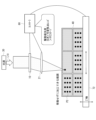
- FIG. 24 shows an example of application of the beam shaping device according to one embodiment to a processing device.
- FIG. 24 shows a configuration example in which the beam shaping device according to modification 8 shown in FIG. 17 is used as the beam shaping device.
- the beam shaping device is applicable to a processing device such as a laser soldering device, for example.
- FIG. 24 shows an example in which parts 81 of various sizes and shapes are soldered onto an electronic circuit board 80.
- a beam shaping device constitutes a laser soldering device that combines the spatial light modulator 10 and the variable focus lens 21.
- the size of the parts 81 changes significantly from several tens of micrometers to several millimeters, and the required resolution and light irradiation range vary depending on the type of parts 81 to be soldered.
- a single focus (fixed focus) lens FIG. 5
- the spatial light modulator 10 displays a phase pattern according to the irradiation pattern irradiated onto the target object, and the optical The device focuses the light modulated by the spatial light modulator 10 toward an object. This makes it possible to modulate the irradiation pattern over a wide range and with high precision.
- the focal spot size and the degree of freedom of the irradiation range are improved, meeting the needs of various irradiation shapes. You will be able to do it.
- the focal length f of the Fourier transform lens variable the focal length f can be made longer in situations where a wide range of steering is required while maintaining diffraction efficiency. In situations where high resolution is required, this can be achieved by shortening the focal length f.
- the present technology can also take the following configuration.
- a spatial light modulator displays a phase pattern corresponding to an irradiation pattern irradiated onto a target object
- an optical device with a variable focal length displays a phase pattern that is modulated by the spatial light modulator. Focuses light onto an object. This makes it possible to modulate the irradiation pattern over a wide range and with high precision.
- a phase modulation spatial light modulator that displays a phase pattern according to the irradiation pattern applied to the target object;
- a beam shaping device comprising: an optical device with a variable focal length that focuses the light modulated by the spatial light modulator toward the target object.
- the spatial light modulator displays, as the phase pattern, a pattern in which a pattern corresponding to the irradiation pattern is superimposed with a focus movement pattern that moves the focus position of the optical device in the vertical direction. beam shaping device.
- the spatial light modulator displays, as the phase pattern, a pattern in which a correction pattern for correcting aberrations caused by the optical device is superimposed on a pattern corresponding to the irradiation pattern. beam shaping device.
- the spatial light modulator displays, as the phase pattern, a pattern in which a correction pattern for correcting aberrations caused by the base material of the object is superimposed on a pattern corresponding to the irradiation pattern.
- the beam shaping device according to any one of the above. (5) further comprising a controller that performs switching control of the phase pattern displayed on the spatial light modulator and switching control of the focal length in the optical device, The controller performs control to give priority to switching control of the phase pattern displayed on the spatial light modulator over control of switching the focal length in the optical device.
- Beam shaping device described in. (6) The beam shaping device according to any one of (1) to (5) above, further comprising a horizontal movement device capable of horizontally moving the object.
- (7) further comprising a controller that performs switching control of the phase pattern displayed on the spatial light modulator, switching control of the focal length in the optical device, and movement control of the horizontal movement device, The controller prioritizes control in the order of switching control of the phase pattern displayed on the spatial light modulator, switching control of the focal length in the optical device, and movement control of the horizontal movement device.
- Beam shaping device The beam shaping device according to any one of (1) to (7) above, further comprising a vertical movement device capable of vertically moving the object, or the spatial light modulator and the optical device. .
- (9) further comprising a controller that performs switching control of the phase pattern displayed on the spatial light modulator, switching control of the focal length in the optical device, and movement control of the vertical movement device, The controller prioritizes control in the order of switching control of the phase pattern displayed on the spatial light modulator, switching control of the focal length in the optical device, and movement control of the vertical movement device.
- Beam shaping device (10) The beam shaping device according to any one of (1) to (9) above, wherein the optical device is a liquid crystal lens with a variable focal length. (11) The beam shaping device according to any one of (1) to (9) above, wherein the optical device is a spatial light modulator with a variable focal length.
- the beam shaping device according to any one of (1) to (9) above, wherein the optical device is a revolver type variable focal length lens.
- the optical device is a liquid lens with a variable focal length.
- a phase modulation spatial light modulator that displays a phase pattern according to the irradiation pattern applied to the object to be processed;
- a processing device comprising: an optical device with a variable focal length that focuses light modulated by the spatial light modulator toward the target object.
Abstract
本開示の一実施の形態に係るビーム整形装置によれば、広範囲かつ高精度な照射パターンの変調を行うことが可能となる。 本開示のビーム整形装置は、対象物(50)に照射する照射パターンに応じた位相パターンを表示する位相変調型の空間光変調器(10)と、空間光変調器によって変調された光を対象物に向けて集光する、焦点距離が可変の光学装置(21)とを備える。
Description
本開示は、位相変調型の空間光変調器(SLM)を用いるビーム整形装置、および加工装置に関する。
例えばレーザ加工の分野において、位相変調型の空間光変調器を用いる方法が提案されている(例えば特許文献1,2参照)。この方法では、空間光変調器に、加工対象の対象物に照射する照射パターンに応じた位相パターンを表示する。また、空間光変調器に表示する位相パターンとしてレンズ機能を与える位相分布を重畳することで、照射パターンを照射する深さ方向(垂直方向)の位置の調整機能を持たせることも提案されている。
空間光変調器にレンズ機能を持たせた場合、位相パターンの空間周波数が上昇し、回折効率が低下する。
広範囲かつ高精度な照射パターンの変調を行うことが可能なビーム整形装置、および加工装置を提供することが望ましい。
本開示の一実施の形態に係るビーム整形装置は、対象物に照射する照射パターンに応じた位相パターンを表示する位相変調型の空間光変調器と、空間光変調器によって変調された光を対象物に向けて集光する、焦点距離が可変の光学装置とを備える。
本開示の一実施の形態に係る加工装置は、加工対象の対象物に照射する照射パターンに応じた位相パターンを表示する位相変調型の空間光変調器と、空間光変調器によって変調された光を対象物に向けて集光する、焦点距離が可変の光学装置とを備える。
本開示の一実施の形態に係るビーム整形装置、または加工装置では、空間光変調器によって、対象物に照射する照射パターンに応じた位相パターンを表示すると共に、焦点距離が可変の光学装置によって、空間光変調器によって変調された光を対象物に向けて集光する。
以下、本開示の実施の形態について図面を参照して詳細に説明する。なお、説明は以下の順序で行う。
0.比較例(図1~図5)
1.一実施の形態
1.1 基本構成および作用(図6~図9)
1.2 変形例および応用例(図10~図24)
1.3 効果
2.その他の実施の形態
0.比較例(図1~図5)
1.一実施の形態
1.1 基本構成および作用(図6~図9)
1.2 変形例および応用例(図10~図24)
1.3 効果
2.その他の実施の形態
<0.比較例>
(位相変調型の空間光変調器(SLM)の概要)
図1に、液晶の誘電異方性の概要を示す。図2に、液晶の屈折率異方性の概要を示す。図3に、位相変調型の空間光変調器の概要を示す。
(位相変調型の空間光変調器(SLM)の概要)
図1に、液晶の誘電異方性の概要を示す。図2に、液晶の屈折率異方性の概要を示す。図3に、位相変調型の空間光変調器の概要を示す。
液晶は誘電異方性を有している。図1に示したように、液晶分子100に電界Eを印加した際に長軸が電界方向に平行になるものを正の誘電異方性、短軸が平行になるものを負の誘電異方性と呼ぶ。また、液晶は液晶分子100の方向によって屈折率が異なる屈折率異方性を有している。図2に示したように、液晶分子100の長軸に平行な方向の屈折率をne、液晶分子100の短軸に平行な方向の屈折率をnoとしたとき、ne>noであり、屈折率neと屈折率noとの差は、屈折率異方性Δn(=ne-no)と呼ばれる。この屈折率異方性があると、入射方向に応じて光に位相差が生じる。
位相変調型の空間光変調器は、上記した液晶の性質を利用して、光の位相のみを変調するデバイスである。図3には、反射型の空間光変調器の一構成例を示す。
空間光変調器は、互いに対向配置された共通電極111と画素電極121との間に、液晶分子100を含む液晶層を挟んだ構造となっている。共通電極111は透明電極であり、液晶層側の面には、配向膜が形成されている。画素電極121における液晶層側の面には、反射膜と配向膜とが形成されている。
液晶分子100にはプレチルト角が付与されており、共通電極111と画素電極121との間に電圧を印加していない(電圧OFF)状態では、プレチルト角の状態で液晶分子100は立った状態となる。共通電極111と画素電極121との間に電圧を印加(電圧ON)することで、液晶分子100が倒れていく。このため、電圧OFFされた状態の画素電極121からの反射光L21と、電圧ONされた状態の画素電極121からの反射光L22とでは、光が通過する際の液晶分子100の状態が異なるため、互いに位相差が生じる。これにより、空間光変調器では、液晶層に印加する電圧を制御することによって、入射光L1の位相をアナログ的に制御することが可能である。
(位相変調型の空間光変調器を利用したビーム整形装置の概要と課題)
図4に、比較例に係るビーム整形装置の第1の構成例を概略的に示す。図5に、比較例に係るビーム整形装置の第2の構成例を概略的に示す。
図4に、比較例に係るビーム整形装置の第1の構成例を概略的に示す。図5に、比較例に係るビーム整形装置の第2の構成例を概略的に示す。
近年、ビーム整形や加工機の分野において位相変調型の空間光変調器を適用することで、性能向上を図ることが期待されている。空間光変調器の利用方法の第1の方法として、図4に示したように、光源30からの入射光L10の位相を空間光変調器10によって変調することによって得られる光分布をそのまま、照射パターンとして被照射面50(加工等の対象物)に照射する方法がある。空間光変調器10は、対象物に照射する照射パターンに応じた位相パターンを表示パターンとして表示する。第1の方法では、空間光変調器10のみによって被照射面50に集光スポット点P1を形成する。この際、空間光変調器10に表示した位相パターンを変化させることのみにより、照射領域中心からの距離xを変化させて照射範囲を変化させる。このため、空間光変調器10に表示する位相パターンが複雑となり、回折効率が低い。
また、第2の方法として、光源30からの入射光L10の位相を空間光変調器10によって変調した後、焦点距離が固定のフーリエ変換レンズ20を介して被照射面50に集光スポット点P1を形成する方法がある。第2の方法では、集光スポット点P1の面内位置(照射領域中心からの距離x)や2次元分布を空間光変調器10によって制御する。上記第1の方法では、空間光変調器10に表示させる位相パターンが複雑となり、回折効率が低い。これに対し、第2の方法では、フーリエ変換レンズ20の集光力によって光を集めるため、効率よく微細なスポットに光を集められるという利点を有しているが、一方で、焦点面から集光点がずれると位相パターンが複雑化し、回折効率が低下する。
実際に、シリコンウエハのダイシングにおいて空間光変調器10が活用されている。この用途では、ウエハ内部にレーザ光を集光することで改質層を形成し、ウエハを切断するというものである。空間光変調器10は基材で発生する収差を補正する役割を担う。この例のように、現状の空間光変調器10を用いた加工は単純な集光点を形成することに限られているため、上記第2の方法では、フーリエ変換レンズ20の焦点は所望のスポットサイズが得られるような焦点距離fであればよい。一方で、空間光変調器10は任意の光2次元分布を形成できることから、より複雑な形状の加工や溶接を実現することが期待できる。複雑な形状とは、深さ方向に加工点が分布していたり、様々なサイズが入り混じった加工を指す。より複雑な加工に空間光変調器10を適用しようとすると、フーリエ変換レンズ20の焦点が固定であることが加工自由度を低下させる要因となる。
固定焦点のフーリエ変換レンズ20を用いた場合、最小スポットサイズと照射範囲とが固定となるため、多様化する照射形状ニーズに応えることは困難である。また、集光スポット点P1の深さ方向の位置は焦点距離fに固定される(図5)。空間光変調器10にフレネルレンズパターン等のレンズ形状の位相パターンを重畳することで焦点距離fの前後に集光スポット点P1を移動させることも可能であるが、焦点面から遠ざかるほど空間光変調器10に表示するフレネルレンズパターンは細かくなるため、回折効率は低下する。
上記第1の方法および上記第2の方法のような空間光変調器10によるビーム整形では、加工などの用途において、すべての照射形状ニーズに応えることは困難である。また、空間光変調器10に表示する位相パターンのみによって深さ方向に焦点を大きく移動させると回折効率が低下し、集光スポット点P1の光強度が低下する。
特許文献1(特開2006-119427号公報)には、レーザ光源から出射された光を位相変調型の空間光変調器によって位相変調を行う際に、入力データに位置移動のための位相分布を重畳するレーザ加工方法が提案されている。また、特許文献2(特開2016-75810号公報)には、空間光変調器上にベッセル光を形成する位相分布に、集光点を移動させるための位相分布を重畳することにより、ベッセル光の照射位置の移動を実現することが提案されている。
しかしながら、特許文献1,2で提案されている光学系において、空間光変調器に焦点移動を行う位相パターンを表示すると、位相パターンの空間周波数が上昇し、回折効率が低下する。これに対し、本開示の技術では、後述するように、焦点距離fが可変の光学装置によって焦点を深さ方向に移動させることが可能であるため、回折効率の低下を抑制することが可能である。
<1.一実施の形態>
[1.1 基本構成および作用]
(概要)
図6に、本開示の一実施の形態に係るビーム整形装置の一構成例を概略的に示す。
[1.1 基本構成および作用]
(概要)
図6に、本開示の一実施の形態に係るビーム整形装置の一構成例を概略的に示す。
一実施の形態に係るビーム整形装置は、位相変調型の空間光変調器10と、焦点距離fが可変の光学装置としての可変焦点レンズ21とを備えている。
空間光変調器10は、入射光L10の位相を変調することにより、表示パターンとして、被照射面50(被加工面、加工等の対象物)に照射する照射パターンに応じた位相パターンを表示する。空間光変調器10は、照射パターンとして、例えば集光スポット点P1を1個以上形成するホログラムを被照射面50に形成する。空間光変調器10には、入射光L10として、ある程度のコヒーレンシーを有する光源30からの光が入射する。光源30としては、レーザ光源はもちろん、ある程度の空間コヒーレンシーを有するLED(Light Emitting Diode)等であってもよい。空間光変調器10は、光源30からの光の位相を変調し、光の干渉によって任意の形状を形成したり、光の進む方向を変調可能である。空間光変調器10は、2次元の画素アレイを有する。空間光変調器10は、反射型でも透過型であってもよい。
可変焦点レンズ21は、空間光変調器10によって変調された光を対象物に向けて集光し、被照射面50に集光スポット点P1を形成する。可変焦点レンズ21は、後述する変形例(図20~図23)に示すように、液晶レンズ22、レボルバー式可変焦点レンズ24、および液体レンズ25などであってもよい。また、照射パターンを形成する空間光変調器10とは別途配置された位相変調型の空間光変調器23であってもよい。
空間光変調器10に表示する位相パターンの空間周波数が上昇すると、回折効率が低下する。一実施の形態に係るビーム整形装置では、空間光変調器10と可変焦点レンズ21とを組み合わせることで、空間光変調器10に表示する位相パターンの空間周波数を低減し、回折効率の低下を抑制する。
一実施の形態に係るビーム整形装置では、深さ方向の焦点移動を可変焦点レンズ21に任せることで、空間光変調器10に表示する位相パターンの空間周波数を低減可能となる。可変焦点レンズ21によって焦点が変調可能であることから、集光スポット点P1を形成できる範囲と解像度との組み合わせを制御可能となる。
一実施の形態に係るビーム整形装置では、比較例に係るビーム整形装置(図5)の構成に対し、焦点距離が固定のフーリエ変換レンズ20を可変焦点レンズ21にしたことにより、焦点面をシフトさせる機能を可変焦点レンズ21によって実現することが可能となる。これにより、空間光変調器10に表示する位相パターンの空間周波数を抑制することが可能である。このため、高い回折効率を実現したまま焦点面を変えることができる。
(分解能と照射可能範囲)
図7に、一実施の形態に係るビーム整形装置における可変焦点レンズ21による作用を概略的に示す。
図7に、一実施の形態に係るビーム整形装置における可変焦点レンズ21による作用を概略的に示す。
ビーム整形装置において、可変焦点レンズ21によって焦点距離fを変調可能である場合、レーザ整形の分解能と光の照射可能範囲とを変えることが可能となる。例えば、入射光L10がガウシアンビームの場合、最小集光スポット径ωminは可変焦点レンズ21に照射するビームの径Dと焦点距離fとで求めることができ、
ωmin=4λf/πD
となる。ただし、λは入射光L10の波長である。焦点距離fが小さいほどNAが大きくなるため、スポット径を小さくすることができる。
ωmin=4λf/πD
となる。ただし、λは入射光L10の波長である。焦点距離fが小さいほどNAが大きくなるため、スポット径を小さくすることができる。
また、集光スポット点P1を形成できる範囲については以下の式で示される。
xmax=f・tanθmax
ただし、θmaxは空間光変調器10の最大回折角である。この式から、焦点距離fが長いほど照射可能な範囲が大きくなることが分かる。
xmax=f・tanθmax
ただし、θmaxは空間光変調器10の最大回折角である。この式から、焦点距離fが長いほど照射可能な範囲が大きくなることが分かる。
集光スポット径と光の照射可能範囲はトレードオフの関係にあり、この関係自体を解決することは難しいが、可変焦点レンズ21を用いることで、所望の集光スポット径か、所望の照射範囲のどちらかを状況に応じて実現することが可能となる。この機能は、例えば様々なサイズの加工パターンが混ざった加工において、加工パターンの大きさに応じて焦点距離fを変えながら加工を行うことで対応することを可能とする。
(空間光変調器10と可変焦点レンズ21との制御方法)
空間光変調器10と可変焦点レンズ21とを組み合わせた場合、制御の順番を工夫することで、例えば加工用途の場合はスループットを最大にすることが可能となる。
空間光変調器10と可変焦点レンズ21とを組み合わせた場合、制御の順番を工夫することで、例えば加工用途の場合はスループットを最大にすることが可能となる。
加工用途の観点での可変焦点レンズ21の機能としては、加工パターンを形成する深さ方向の位置を変調する機能と、加工パターンのサイズおよび分解能を変調する機能とがある。加工対象物が立体であったり、加工形状の大きさが様々である場合、加工の最中に可変焦点レンズ21の焦点距離fを変化させながら加工を進めることになる。一般的に、可変焦点レンズ21の駆動速度は空間光変調器10の駆動速度よりも遅い。このため、可変焦点レンズ21の焦点距離fを切り替える回数を低減することで、加工スループットを最大化することが可能である。
図8および図9に、一実施の形態に係るビーム整形装置を用いた加工方法の一例を概略的に示す。
図8に示したように、加工点P2が深さ方向に分布する場合、同じ深さの加工点P2を順々に処理していくことでスループットを最大化することができる。すなわち、ある深さの加工点P2をすべて処理した後に、焦点距離fを順々に切り替え、別の深さの加工点P2を順々に処理していくことで、可変焦点レンズ21の焦点距離fを切り替える回数を低減し、スループットを最大化することができる。
また、図9に示したように、加工対象物として同一面内において加工サイズが異なる様々なものがある場合、サイズが同等であるものに分けて加工を行うことで、スループットを最大化することができる。例えば、図9において、サイズが同等の加工対象物として、対象物S1、対象物S2、対象物S3、対象物S4があり、サイズがS1>S2>S3>S4の関係にある場合、各サイズの加工対象物ごとに焦点を決めて、まとめて加工することで、可変焦点レンズ21の焦点距離fを切り替える回数を低減し、スループットを最大化することができる。
[1.2 変形例および応用例]
(変形例1)
図10に、変形例1に係るビーム整形装置の一構成例を概略的に示す。
(変形例1)
図10に、変形例1に係るビーム整形装置の一構成例を概略的に示す。
変形例1に係るビーム整形装置では、空間光変調器10が表示する位相パターンとして、照射パターンに対応するパターン(スポット位置制御パターン)に、可変焦点レンズ21による焦点位置を垂直方向(深さ方向)に移動させる焦点移動用パターンを重畳したパターンを表示する。
位相パターンとして、空間光変調器10が回折効率が低下しない程度の焦点移動用パターンを重畳することにより、可変焦点レンズ21の焦点を深さ方向にシフトさせることが可能となる。さらに、被照射面50における0次回折光がデフォーカスされるため、0次回折光の集光点で対象物が加工されることを防ぐことが可能となる。また、例えば、可変焦点レンズ21を、後述するレボルバー式可変焦点レンズ24(図22)にした場合、可変可能な焦点距離fは間欠的になる。この場合、レボルバーの中に含まれていない焦点距離fの位置に光を集光したい場合には、位相パターンとして空間光変調器10にレボルバー式可変焦点レンズ24に含まれない焦点距離fに対応するレンズのパターンを重畳することで、レボルバー式可変焦点レンズ24に含まれない焦点距離fを補完することが可能となる。
その他の構成および作用は、上記一実施の形態に係るビーム整形装置の構成(図6)と略同様であってもよい。
(変形例2)
図11に、変形例2に係るビーム整形装置の一構成例を概略的に示す。
図11に、変形例2に係るビーム整形装置の一構成例を概略的に示す。
変形例2に係るビーム整形装置では、空間光変調器10が表示する位相パターンとして、照射パターンに対応するパターン(スポット位置制御パターン)に、可変焦点レンズ21によって生ずる収差を補正する補正用パターンを重畳したパターンを表示する。
一般的に可変焦点レンズ21は収差を有する。その収差が既知である場合、位相パターンとして収差を補正する補正用パターンを重畳することにより、可変焦点レンズ21で生じる収差を空間光変調器10に表示する補正用パターンよって相殺することができ、集光スポット径を最小化することが可能である。これにより、集光スポット点P1の解像度の向上を図ることができる。
その他の構成および作用は、上記一実施の形態に係るビーム整形装置の構成(図6)と略同様であってもよい。
(変形例3)
図12に、変形例3に係るビーム整形装置の一構成例を概略的に示す。
図12に、変形例3に係るビーム整形装置の一構成例を概略的に示す。
変形例3に係るビーム整形装置では、空間光変調器10が表示する位相パターンとして、照射パターンに対応するパターン(スポット位置制御パターン)に、被照射面50(加工等の対象物)の基材40によって生ずる収差を補正する補正用パターンを重畳したパターンを表示する。
屈折率nを有する厚みのある基材40の内部の被照射面50に加工を施す場合、基材40の中を収束光が伝搬するため、収差が生じる。この収差を補正するため、照射パターンに対応するパターンに、基材40の屈折率nと基材40の厚みとに応じた補正用パターンを重畳することにより、基材40の内部でも集光スポット径を最小化することが可能となる。これにより、集光スポット点P1の解像度の向上を図ることができる。上
その他の構成および作用は、上記一実施の形態に係るビーム整形装置の構成(図6)と略同様であってもよい。
(変形例4)
図13に、変形例4に係るビーム整形装置の一構成例を概略的に示す。
図13に、変形例4に係るビーム整形装置の一構成例を概略的に示す。
変形例4に係るビーム整形装置では、空間光変調器10に表示する位相パターンの切り替え制御と可変焦点レンズ21における焦点距離fの切り替え制御とを行うコントローラ60をさらに備える。コントローラ60は、可変焦点レンズ21における焦点距離fの切り替え制御よりも、空間光変調器10に表示する位相パターンの切り替え制御を優先させる制御を行う。
一般的に、可変焦点レンズ21の駆動速度よりも空間光変調器10の駆動速度の方が速いため、「空間光変調器10に表示する位相パターンの切り替え時間<焦点移動時間(焦点距離fの切り替え時間)」となる。このため、空間光変調器10の駆動を優先し、ある焦点距離fにおける空間光変調器10の位相パターンをすべて変化させたのち、焦点距離fを変更した方が、可変焦点レンズ21の駆動回数を低減し、全体としてのスループットを最大化することが可能である。これは、例えば、図13に示したように、基材40の水平面内と深さ方向とに加工点P2が複数存在し、加工点P2が階層的となっている場合に効果的である。例えば、各階層面内の加工点P2を加工するために、焦点距離をf1,f2,…fmに切り替え、各階層面において空間光変調器10に複数の位相パターン1,2,…nを表示する必要がある場合、以下のような順番で切り替え制御を行う。
位相パターン1→位相パターン2→…位相パターンn
→焦点距離f1に切り替え
→位相パターン1→位相パターン2→…位相パターンn
→焦点距離f2に切り替え
…
→位相パターン1→位相パターン2→…位相パターンn
→焦点距離fmに切り替え
位相パターン1→位相パターン2→…位相パターンn
→焦点距離f1に切り替え
→位相パターン1→位相パターン2→…位相パターンn
→焦点距離f2に切り替え
…
→位相パターン1→位相パターン2→…位相パターンn
→焦点距離fmに切り替え
その他の構成および作用は、上記一実施の形態に係るビーム整形装置の構成(図6)と略同様であってもよい。
(変形例5)
図14に、変形例5に係るビーム整形装置の一構成例を概略的に示す。
図14に、変形例5に係るビーム整形装置の一構成例を概略的に示す。
変形例5に係るビーム整形装置の構成は、変形例4に係るビーム整形装置と同様に、空間光変調器10に表示する位相パターンの切り替え制御と可変焦点レンズ21における焦点距離fの切り替え制御とを行うコントローラ60をさらに備える。コントローラ60は、可変焦点レンズ21における焦点距離fの切り替え制御よりも、空間光変調器10に表示する位相パターンの切り替え制御を優先させる制御を行う。
変形例4(図13)では、深さの異なる位置に存在する加工点P2を加工するために、可変焦点レンズ21における焦点距離fの切り替え制御を行う例を挙げたが、加工サイズが異なる加工対象物が同一面内に複数存在する場合においても、焦点距離fの切り替え制御を行う場合が生じ得る。そのような場合、ある大きさの加工パターンをすべて処理したのち、焦点距離fを変更した方が、可変焦点レンズ21の焦点距離fを切り替える回数を低減し、スループットを最大化することができる。図14の例では、同一の被照射面50に、50μmの加工パターンと1mmの加工パターンとが存在し、50μmの加工パターンと1mmの加工パターンとで焦点距離fを切り替える場合の例を示す。例えば、同一の被照射面50において、複数の大きさの加工パターンを処理するために、焦点距離をf1,f2,…fmに切り替える必要がある場合、以下のような順番で切り替え制御を行う。
例えば、
10μm~100μmの加工パターンを処理
→焦点距離f1に切り替え
→100μm~1mmの加工パターンを処理
→焦点距離f2に切り替え
…
→焦点可変m
例えば、
10μm~100μmの加工パターンを処理
→焦点距離f1に切り替え
→100μm~1mmの加工パターンを処理
→焦点距離f2に切り替え
…
→焦点可変m
その他の構成および作用は、上記一実施の形態に係るビーム整形装置の構成(図6)と略同様であってもよい。
(変形例6)
図15に、変形例6に係るビーム整形装置の一構成例を概略的に示す。
図15に、変形例6に係るビーム整形装置の一構成例を概略的に示す。
変形例6に係るビーム整形装置は、対象物を水平方向(XY方向)に移動させることが可能な水平移動装置としてのXYステージ70をさらに備える。また、変形例6に係るビーム整形装置は、空間光変調器10に表示する位相パターンの切り替え制御と、可変焦点レンズ21における焦点距離fの切り替え制御と、XYステージ70の移動制御とを行うコントローラ60をさらに備える。
空間光変調器10によって集光スポット点P1を移動できる範囲は空間光変調器10の最大回折角に制限される。空間光変調器10とXYステージ70とを組み合わせることで、加工対象物を動かしながら大面積への加工が可能となり、加工面積を向上させることができる。
その他の構成および作用は、上記一実施の形態に係るビーム整形装置の構成(図6)と略同様であってもよい。
(変形例7)
図16に、変形例7に係るビーム整形装置の一構成例を概略的に示す。
図16に、変形例7に係るビーム整形装置の一構成例を概略的に示す。
変形例7に係るビーム整形装置は、変形例6に係るビーム整形装置と同様に、対象物を水平方向(XY方向)に移動させることが可能な水平移動装置としてのXYステージ70をさらに備える。また、変形例7に係るビーム整形装置は、変形例6に係るビーム整形装置と同様に、空間光変調器10に表示する位相パターンの切り替え制御と、可変焦点レンズ21における焦点距離fの切り替え制御と、XYステージ70の移動制御とを行うコントローラ60をさらに備える。
変形例7に係るビーム整形装置では、コントローラ60は、空間光変調器10に表示する位相パターンの切り替え制御、可変焦点レンズ21における焦点距離fの切り替え制御、XYステージ70の移動制御の順に制御を優先させる。一般的に、空間光変調器10と可変焦点レンズ21とXYステージ70とでは、この順に駆動速度が速いため、「空間光変調器10に表示する位相パターンの切り替え時間<焦点移動時間(焦点距離fの切り替え時間)<XYステージ70の駆動時間」となる。このため、空間光変調器10に表示する位相パターンの切り替え制御、可変焦点レンズ21における焦点距離fの切り替え制御、XYステージ70の移動制御の順に駆動を優先させることで、加工面積を向上させつつ、全体としてのスループットを最大化することが可能である。例えば、図16に示したように、基材40の水平面内と深さ方向とに加工点P2が複数存在し、加工点P2が階層的となっている場合において、各階層面内の加工点P2を加工するために、焦点距離をf1,f2,…fmに切り替え、各階層面において空間光変調器10に複数の位相パターン1,2,…nを表示する必要があり、さらにXYステージ70によって基材40を移動させる必要がある場合、以下のような順番で切り替え制御を行う。
例えば、
位相パターン1→位相パターン2→…位相パターンn
→焦点距離f1に切り替え
→位相パターン1→位相パターン2→…位相パターンn
→焦点距離f2に切り替え
…
→位相パターン1→位相パターン2→…位相パターンn
→焦点距離fmに切り替え
→XYステージ70による移動
→位相パターン1→位相パターン2→…位相パターンn
→焦点距離f1に切り替え
→…
例えば、
位相パターン1→位相パターン2→…位相パターンn
→焦点距離f1に切り替え
→位相パターン1→位相パターン2→…位相パターンn
→焦点距離f2に切り替え
…
→位相パターン1→位相パターン2→…位相パターンn
→焦点距離fmに切り替え
→XYステージ70による移動
→位相パターン1→位相パターン2→…位相パターンn
→焦点距離f1に切り替え
→…
その他の構成および作用は、上記一実施の形態に係るビーム整形装置の構成(図6)と略同様であってもよい。
(変形例8)
図17に、変形例8に係るビーム整形装置の第1の構成例を概略的に示す。図18に、変形例8に係るビーム整形装置の第2の構成例を概略的に示す。
図17に、変形例8に係るビーム整形装置の第1の構成例を概略的に示す。図18に、変形例8に係るビーム整形装置の第2の構成例を概略的に示す。
変形例8に係るビーム整形装置は、対象物、または空間光変調器10および可変焦点レンズ21を垂直方向(Z軸方向)に移動させることが可能な垂直移動装置をさらに備える。
図17に示した第1の構成例では、対象物を水平方向(XY方向)に移動させることが可能な水平移動装置としてのXYステージ70と、Z軸駆動装置71とを備えた例を示す。Z軸駆動装置71は、空間光変調器10および可変焦点レンズ21を垂直方向(Z軸方向)に移動させることが可能な垂直移動装置である。また、図17に示した第1の構成例では、空間光変調器10に表示する位相パターンの切り替え制御と、可変焦点レンズ21における焦点距離fの切り替え制御と、Z軸駆動装置71およびXYステージ70の移動制御とを行うコントローラ60をさらに備える。
図18に示した第2の構成例では、対象物を水平方向(XY方向)と垂直方向(Z軸方向)とに移動させることが可能な水平移動装置、かつ垂直移動装置としてのXYZステージ72を備えた例を示す。また、図18に示した第2の構成例では、空間光変調器10に表示する位相パターンの切り替え制御と、可変焦点レンズ21における焦点距離fの切り替え制御と、XYZステージ72の移動制御とを行うコントローラ60をさらに備える。
可変焦点レンズ21によって焦点距離fを変化させた場合、光の照射可能範囲や分解能も同時に変化するが、加工ボクセルサイズが深さ方向に変化すると困る用途もある。また、可変焦点レンズ21の焦点距離fから大幅に離れた位置にスポットを移動すると、回折効率が低下する。この課題に対して、Z軸方向に光学系を移動する装置やZ軸ステージを用いることで、空間光変調器10および可変焦点レンズ21と加工対象物との距離を変化させることができ、可変焦点レンズ21の焦点距離fを大きく変えることなく、高い回折効率を維持したまま、加工対象物を加工することが可能となる。また、光の照射可能範囲と解像度の自由度を向上させることができる。
その他の構成および作用は、上記一実施の形態に係るビーム整形装置の構成(図6)と略同様であってもよい。
(変形例9)
図19に、変形例9に係るビーム整形装置の一構成例を概略的に示す。
図19に、変形例9に係るビーム整形装置の一構成例を概略的に示す。
図17および図18に示した変形例8に係るビーム整形装置において、コントローラ60は、空間光変調器10に表示する位相パターンの切り替え制御、可変焦点レンズ21における焦点距離fの切り替え制御、垂直移動装置の移動制御の順に制御を優先させるようにしてもよい。
図19には、図18に示した変形例8に係るビーム整形装置の第2の構成例に対応する構成例を示す。以下では、垂直移動装置がXYZステージ72である場合の制御を例に説明する。一般的に、空間光変調器10と可変焦点レンズ21とXYZステージ72とでは、この順に駆動速度が速いため、「空間光変調器10に表示する位相パターンの切り替え時間<焦点移動時間(焦点距離fの切り替え時間)<XYZステージ72の駆動時間」となる。このため、空間光変調器10に表示する位相パターンの切り替え制御、可変焦点レンズ21における焦点距離fの切り替え制御、XYZステージ72の移動制御の順に駆動を優先させることで、加工面積を向上させつつ、全体としてのスループットを最大化することが可能である。例えば、図19に示したように、基材40の水平面内と深さ方向とに加工点P2が複数存在し、加工点P2が階層的となっている場合において、各階層面内の加工点P2を加工するために、焦点距離をf1,f2,…fmに切り替え、各階層面において空間光変調器10に複数の位相パターン1,2,…nを表示する必要があり、さらにXYZステージ72によって基材40を移動させる必要がある場合、以下のような順番で切り替え制御を行う。
例えば、
位相パターン1→位相パターン2→…位相パターンn
→焦点距離f1に切り替え
→位相パターン1→位相パターン2→…位相パターンn
→焦点距離f2に切り替え
…
→位相パターン1→位相パターン2→…位相パターンn
→焦点距離fmに切り替え
→XYZステージ72による移動
→位相パターン1→位相パターン2→…位相パターンn
→焦点距離f1に切り替え
→…
例えば、
位相パターン1→位相パターン2→…位相パターンn
→焦点距離f1に切り替え
→位相パターン1→位相パターン2→…位相パターンn
→焦点距離f2に切り替え
…
→位相パターン1→位相パターン2→…位相パターンn
→焦点距離fmに切り替え
→XYZステージ72による移動
→位相パターン1→位相パターン2→…位相パターンn
→焦点距離f1に切り替え
→…
その他の構成および作用は、上記一実施の形態に係るビーム整形装置の構成(図6)と略同様であってもよい。
(変形例10)
図20に、変形例10に係るビーム整形装置の一構成例を概略的に示す。
図20に、変形例10に係るビーム整形装置の一構成例を概略的に示す。
変形例10に係るビーム整形装置は、焦点距離fが可変の光学装置として、焦点距離fが可変の液晶レンズ22を備えている。
焦点距離fが可変の光学装置として液晶レンズ22を用いることで、焦点距離fが可変の光学装置の薄型化、光学系の軽量化、および小型化を図ることができる。また、連続的な焦点距離fの調整が可能となる。
その他の構成および作用は、上記一実施の形態に係るビーム整形装置の構成(図6)と略同様であってもよい。
(変形例11)
図21に、変形例11に係るビーム整形装置の一構成例を概略的に示す。
図21に、変形例11に係るビーム整形装置の一構成例を概略的に示す。
変形例11に係るビーム整形装置は、焦点距離fが可変の光学装置として、焦点距離fが可変の空間光変調器23を備えている。
空間光変調器10は、対象物に照射する照射パターンに応じた位相パターンを表示パターンとして表示する。一方、空間光変調器23は、位相パターンとして、焦点距離fが可変の光学装置として機能させるためのレンズパターンを表示する。焦点距離fが可変の光学装置として空間光変調器23を用いることで、焦点距離fが可変の光学装置の薄型化、光学系の軽量化、および小型化を図ることができる。また、連続的な焦点距離fの調整が可能となる。
なお、液晶レンズ22(図20)と空間光変調器23は、液晶を電圧駆動する構成であることは同じであるが、液晶レンズ22ではレンズ機能のみを実現するために電極形状が例えば円形になっている。空間光変調器23の場合は、例えば矩形の画素アレイで構成される。なお、液晶レンズ22の構成としては、フレネルレンズを組み合わせた方式や、コレステリック液晶を用いる方式などが存在するが、焦点距離fが可変の光学装置として用いる液晶レンズ22の種類はこれらに限らない。
その他の構成および作用は、上記一実施の形態に係るビーム整形装置の構成(図6)と略同様であってもよい。
(変形例12)
図22に、変形例12に係るビーム整形装置の一構成例を概略的に示す。
図22に、変形例12に係るビーム整形装置の一構成例を概略的に示す。
変形例12に係るビーム整形装置は、焦点距離fが可変の光学装置として、焦点距離fが異なる複数のレンズを有するレボルバー式焦点距離可変レンズ24を備えている。
焦点距離fが可変の光学装置としてレボルバー式焦点距離可変レンズ24を用いることで、設計ノウハウが蓄積された屈折レンズを採用することが可能となり、収差を抑えることが容易となる。なお、レボルバー式焦点距離可変レンズ24では、焦点調節が離散的となるが、レボルバーの中に含まれていない焦点距離fの位置に光を集光したい場合には、位相パターンとして空間光変調器10にレボルバー式可変焦点レンズ24に含まれない焦点距離fに対応するレンズのパターンを重畳することで、レボルバー式可変焦点レンズ24に含まれない焦点距離fを補完することが可能となる。この場合、空間光変調器10に表示する位相パターンの空間周波数が高くなり、回折効率が低下することが予想されるが、空間光変調器10のみによって光変調を行う場合(図4)や固定焦点のフーリエ変換レンズ20を用いる場合(図5)と比較して、位相パターンの空間周波数を低減することが可能であるため、回折効率が向上する。
その他の構成および作用は、上記一実施の形態に係るビーム整形装置の構成(図6)と略同様であってもよい。
(変形例13)
図23に、変形例13に係るビーム整形装置の一構成例を概略的に示す。
図23に、変形例13に係るビーム整形装置の一構成例を概略的に示す。
変形例10に係るビーム整形装置は、焦点距離fが可変の光学装置として、焦点距離fが可変の液体レンズ25を備えている。
焦点距離fが可変の光学装置として液体レンズ25を用いることで、連続的な焦点距離fの調整が可能となる。
その他の構成および作用は、上記一実施の形態に係るビーム整形装置の構成(図6)と略同様であってもよい。
(応用例)
図24に、一実施の形態に係るビーム整形装置の加工装置への応用例を示す。図24には、ビーム整形装置として、図17に示した変形例8に係るビーム整形装置を用いた場合の構成例を示す。
図24に、一実施の形態に係るビーム整形装置の加工装置への応用例を示す。図24には、ビーム整形装置として、図17に示した変形例8に係るビーム整形装置を用いた場合の構成例を示す。
一実施の形態に係るビーム整形装置は、例えばレーザはんだ装置等の加工装置に適用可能である。図24には、電子回路基板80上に様々な大きさや形状のパーツ81をはんだ付け加工する場合の例を示す。例えば、一実施の形態に係るビーム整形装置によって、空間光変調器10と可変焦点レンズ21とを組み合わせたレーザはんだ装置を構成する。はんだ付けではパーツ81の大きさが数十μmから数ミリまで大幅に変化し、はんだ付けするパーツ81の種類によって、要求される解像度や光の照射範囲は異なる。単一焦点(固定焦点)のレンズを用いた場合(図5)、様々な大きさや形状のパーツ81に対応することは困難である。可変焦点レンズ21を用いることで、様々な大きさや形状のパーツ81に対応することが可能となる。
その他の構成および作用は、上記一実施の形態に係るビーム整形装置の構成(図6)と略同様であってもよい。
[1.3 効果]
以上説明したように、一実施の形態に係るビーム整形装置によれば、空間光変調器10によって、対象物に照射する照射パターンに応じた位相パターンを表示すると共に、焦点距離fが可変の光学装置によって、空間光変調器10によって変調された光を対象物に向けて集光する。これにより、広範囲かつ高精度な照射パターンの変調を行うことが可能となる。
以上説明したように、一実施の形態に係るビーム整形装置によれば、空間光変調器10によって、対象物に照射する照射パターンに応じた位相パターンを表示すると共に、焦点距離fが可変の光学装置によって、空間光変調器10によって変調された光を対象物に向けて集光する。これにより、広範囲かつ高精度な照射パターンの変調を行うことが可能となる。
一実施の形態に係るビーム整形装置によれば、空間光変調器10と可変焦点レンズ21とを組み合わせることにより、焦点スポットサイズと照射範囲の自由度が向上し、様々な照射形状のニーズに応えられるようになる。深さ方向の焦点移動を可変焦点レンズ21に任せることで回折効率の低下を抑制可能となる。また、一実施の形態に係るビーム整形装置によれば、フーリエ変換レンズの焦点距離fを可変にすることで、回折効率を維持したまま広範囲のステアリングが必要な場面では焦点距離fを長くすることで対応し、分解能が必要な場面では焦点距離fを短くすることで対応することが可能となる。
なお、本明細書に記載された効果はあくまでも例示であって限定されるものではなく、また他の効果があってもよい。以降の他の実施の形態の効果についても同様である。
<2.その他の実施の形態>
本開示による技術は、上記一実施の形態の説明に限定されず種々の変形実施が可能である。
本開示による技術は、上記一実施の形態の説明に限定されず種々の変形実施が可能である。
例えば、本技術は以下のような構成を取ることもできる。
以下の構成の本技術によれば、空間光変調器によって、対象物に照射する照射パターンに応じた位相パターンを表示すると共に、焦点距離が可変の光学装置によって、空間光変調器によって変調された光を対象物に向けて集光する。これにより、広範囲かつ高精度な照射パターンの変調を行うことが可能となる。
以下の構成の本技術によれば、空間光変調器によって、対象物に照射する照射パターンに応じた位相パターンを表示すると共に、焦点距離が可変の光学装置によって、空間光変調器によって変調された光を対象物に向けて集光する。これにより、広範囲かつ高精度な照射パターンの変調を行うことが可能となる。
(1)
対象物に照射する照射パターンに応じた位相パターンを表示する位相変調型の空間光変調器と、
前記空間光変調器によって変調された光を前記対象物に向けて集光する、焦点距離が可変の光学装置と
を備える
ビーム整形装置。
(2)
前記空間光変調器は、前記位相パターンとして、前記照射パターンに対応するパターンに、前記光学装置による焦点位置を垂直方向に移動させる焦点移動用パターンを重畳したパターンを表示する
上記(1)に記載のビーム整形装置。
(3)
前記空間光変調器は、前記位相パターンとして、前記照射パターンに対応するパターンに、前記光学装置によって生ずる収差を補正する補正用パターンを重畳したパターンを表示する
上記(1)または(2)に記載のビーム整形装置。
(4)
前記空間光変調器は、前記位相パターンとして、前記照射パターンに対応するパターンに、前記対象物の基材によって生ずる収差を補正する補正用パターンを重畳したパターンを表示する
上記(1)ないし(3)のいずれか1つに記載のビーム整形装置。
(5)
前記空間光変調器に表示する前記位相パターンの切り替え制御と前記光学装置における前記焦点距離の切り替え制御とを行うコントローラ、をさらに備え、
前記コントローラは、前記光学装置における前記焦点距離の切り替え制御よりも、前記空間光変調器に表示する前記位相パターンの切り替え制御を優先させる制御を行う
上記(1)ないし(4)のいずれか1つに記載のビーム整形装置。
(6)
前記対象物を水平方向に移動させることが可能な水平移動装置、をさらに備える
上記(1)ないし(5)のいずれか1つに記載のビーム整形装置。
(7)
前記空間光変調器に表示する前記位相パターンの切り替え制御と、前記光学装置における前記焦点距離の切り替え制御と、前記水平移動装置の移動制御とを行うコントローラ、をさらに備え、
前記コントローラは、前記空間光変調器に表示する前記位相パターンの切り替え制御、前記光学装置における前記焦点距離の切り替え制御、前記水平移動装置の移動制御の順に制御を優先させる
上記(6)に記載のビーム整形装置。
(8)
前記対象物、または前記空間光変調器および前記光学装置を垂直方向に移動させることが可能な垂直移動装置、をさらに備える
上記(1)ないし(7)のいずれか1つに記載のビーム整形装置。
(9)
前記空間光変調器に表示する前記位相パターンの切り替え制御と、前記光学装置における前記焦点距離の切り替え制御と、前記垂直移動装置の移動制御とを行うコントローラ、をさらに備え、
前記コントローラは、前記空間光変調器に表示する前記位相パターンの切り替え制御、前記光学装置における前記焦点距離の切り替え制御、前記垂直移動装置の移動制御の順に制御を優先させる
上記(8)に記載のビーム整形装置。
(10)
前記光学装置は、焦点距離が可変の液晶レンズである
上記(1)ないし(9)のいずれか1つに記載のビーム整形装置。
(11)
前記光学装置は、焦点距離が可変の空間光変調器である
上記(1)ないし(9)のいずれか1つに記載のビーム整形装置。
(12)
前記光学装置は、レボルバー式焦点距離可変レンズである
上記(1)ないし(9)のいずれか1つに記載のビーム整形装置。
(13)
前記光学装置は、焦点距離が可変の液体レンズである
上記(1)ないし(9)のいずれか1つに記載のビーム整形装置。
(14)
加工対象の対象物に照射する照射パターンに応じた位相パターンを表示する位相変調型の空間光変調器と、
前記空間光変調器によって変調された光を前記対象物に向けて集光する、焦点距離が可変の光学装置と
を備える
加工装置。
本出願は、日本国特許庁において2022年5月24日に出願された日本特許出願番号第2022-084837号を基礎として優先権を主張するものであり、この出願のすべての内容を参照によって本出願に援用する。
当業者であれば、設計上の要件や他の要因に応じて、種々の修正、コンビネーション、サブコンビネーション、および変更を想到し得るが、それらは添付の請求の範囲やその均等物の範囲に含まれるものであることが理解される。
Claims (14)
- 対象物に照射する照射パターンに応じた位相パターンを表示する位相変調型の空間光変調器と、
前記空間光変調器によって変調された光を前記対象物に向けて集光する、焦点距離が可変の光学装置と
を備える
ビーム整形装置。 - 前記空間光変調器は、前記位相パターンとして、前記照射パターンに対応するパターンに、前記光学装置による焦点位置を垂直方向に移動させる焦点移動用パターンを重畳したパターンを表示する
請求項1に記載のビーム整形装置。 - 前記空間光変調器は、前記位相パターンとして、前記照射パターンに対応するパターンに、前記光学装置によって生ずる収差を補正する補正用パターンを重畳したパターンを表示する
請求項1に記載のビーム整形装置。 - 前記空間光変調器は、前記位相パターンとして、前記照射パターンに対応するパターンに、前記対象物の基材によって生ずる収差を補正する補正用パターンを重畳したパターンを表示する
請求項1に記載のビーム整形装置。 - 前記空間光変調器に表示する前記位相パターンの切り替え制御と前記光学装置における前記焦点距離の切り替え制御とを行うコントローラ、をさらに備え、
前記コントローラは、前記光学装置における前記焦点距離の切り替え制御よりも、前記空間光変調器に表示する前記位相パターンの切り替え制御を優先させる制御を行う
請求項1に記載のビーム整形装置。 - 前記対象物を水平方向に移動させることが可能な水平移動装置、をさらに備える
請求項1に記載のビーム整形装置。 - 前記空間光変調器に表示する前記位相パターンの切り替え制御と、前記光学装置における前記焦点距離の切り替え制御と、前記水平移動装置の移動制御とを行うコントローラ、をさらに備え、
前記コントローラは、前記空間光変調器に表示する前記位相パターンの切り替え制御、前記光学装置における前記焦点距離の切り替え制御、前記水平移動装置の移動制御の順に制御を優先させる
請求項6に記載のビーム整形装置。 - 前記対象物、または前記空間光変調器および前記光学装置を垂直方向に移動させることが可能な垂直移動装置、をさらに備える
請求項1に記載のビーム整形装置。 - 前記空間光変調器に表示する前記位相パターンの切り替え制御と、前記光学装置における前記焦点距離の切り替え制御と、前記垂直移動装置の移動制御とを行うコントローラ、をさらに備え、
前記コントローラは、前記空間光変調器に表示する前記位相パターンの切り替え制御、前記光学装置における前記焦点距離の切り替え制御、前記垂直移動装置の移動制御の順に制御を優先させる
請求項8に記載のビーム整形装置。 - 前記光学装置は、焦点距離が可変の液晶レンズである
請求項1に記載のビーム整形装置。 - 前記光学装置は、焦点距離が可変の空間光変調器である
請求項1に記載のビーム整形装置。 - 前記光学装置は、レボルバー式焦点距離可変レンズである
請求項1に記載のビーム整形装置。 - 前記光学装置は、焦点距離が可変の液体レンズである
請求項1に記載のビーム整形装置。 - 加工対象の対象物に照射する照射パターンに応じた位相パターンを表示する位相変調型の空間光変調器と、
前記空間光変調器によって変調された光を前記対象物に向けて集光する、焦点距離が可変の光学装置と
を備える
加工装置。
Applications Claiming Priority (2)
| Application Number | Priority Date | Filing Date | Title |
|---|---|---|---|
| JP2022084837 | 2022-05-24 | ||
| JP2022-084837 | 2022-05-24 |
Publications (1)
| Publication Number | Publication Date |
|---|---|
| WO2023228548A1 true WO2023228548A1 (ja) | 2023-11-30 |
Family
ID=88919050
Family Applications (1)
| Application Number | Title | Priority Date | Filing Date |
|---|---|---|---|
| PCT/JP2023/012269 WO2023228548A1 (ja) | 2022-05-24 | 2023-03-27 | ビーム整形装置、および加工装置 |
Country Status (1)
| Country | Link |
|---|---|
| WO (1) | WO2023228548A1 (ja) |
Citations (7)
| Publication number | Priority date | Publication date | Assignee | Title |
|---|---|---|---|---|
| JP2011051011A (ja) * | 2009-08-03 | 2011-03-17 | Hamamatsu Photonics Kk | レーザ加工方法及び半導体装置の製造方法 |
| JP2013043204A (ja) * | 2011-08-24 | 2013-03-04 | Hamamatsu Photonics Kk | レーザ加工方法 |
| WO2013157606A1 (ja) * | 2012-04-20 | 2013-10-24 | 浜松ホトニクス株式会社 | ビームエクスパンダ |
| JP2015024428A (ja) * | 2013-07-26 | 2015-02-05 | 住友大阪セメント株式会社 | 加工装置 |
| JP2016055319A (ja) * | 2014-09-10 | 2016-04-21 | 浜松ホトニクス株式会社 | 光照射装置および光照射方法 |
| CN108161250A (zh) * | 2018-01-30 | 2018-06-15 | 苏州德龙激光股份有限公司 | 多焦点动态分布激光加工脆性透明材料的方法及装置 |
| JP2019512397A (ja) * | 2016-03-17 | 2019-05-16 | エレクトロ サイエンティフィック インダストリーズ インコーポレーテッド | レーザ加工システムにおける像平面の配置 |
-
2023
- 2023-03-27 WO PCT/JP2023/012269 patent/WO2023228548A1/ja unknown
Patent Citations (7)
| Publication number | Priority date | Publication date | Assignee | Title |
|---|---|---|---|---|
| JP2011051011A (ja) * | 2009-08-03 | 2011-03-17 | Hamamatsu Photonics Kk | レーザ加工方法及び半導体装置の製造方法 |
| JP2013043204A (ja) * | 2011-08-24 | 2013-03-04 | Hamamatsu Photonics Kk | レーザ加工方法 |
| WO2013157606A1 (ja) * | 2012-04-20 | 2013-10-24 | 浜松ホトニクス株式会社 | ビームエクスパンダ |
| JP2015024428A (ja) * | 2013-07-26 | 2015-02-05 | 住友大阪セメント株式会社 | 加工装置 |
| JP2016055319A (ja) * | 2014-09-10 | 2016-04-21 | 浜松ホトニクス株式会社 | 光照射装置および光照射方法 |
| JP2019512397A (ja) * | 2016-03-17 | 2019-05-16 | エレクトロ サイエンティフィック インダストリーズ インコーポレーテッド | レーザ加工システムにおける像平面の配置 |
| CN108161250A (zh) * | 2018-01-30 | 2018-06-15 | 苏州德龙激光股份有限公司 | 多焦点动态分布激光加工脆性透明材料的方法及装置 |
Similar Documents
| Publication | Publication Date | Title |
|---|---|---|
| JP6258787B2 (ja) | レーザ加工装置及びレーザ加工方法 | |
| US7157661B2 (en) | Method and apparatus for laser machining | |
| JP6272145B2 (ja) | レーザ加工装置及びレーザ加工方法 | |
| US10228552B2 (en) | Structured illuminating microscopy and structured illuminating observation method | |
| KR102250704B1 (ko) | 레이저 가공 장치 및 레이저 가공 방법 | |
| JP5836415B2 (ja) | レーザ加工方法及び半導体装置の製造方法 | |
| CN111014947A (zh) | 基于空间光调制器和扫描振镜的高速激光加工装置和方法 | |
| JP4729883B2 (ja) | 基板の加工方法、マイクロレンズシートの製造方法、透過型スクリーン、プロジェクタ、表示装置並びに基板の加工装置 | |
| WO2011016296A1 (ja) | レーザ加工方法 | |
| US9146393B2 (en) | Structured illumination apparatus, structured illumination microscopy, and structured illumination method | |
| KR20220079949A (ko) | 세그먼트화된 빔 정형 요소 및 레이저 가공 시스템 | |
| US11465235B2 (en) | Laser light irradiating device | |
| WO2023228548A1 (ja) | ビーム整形装置、および加工装置 | |
| EP2683516B1 (en) | Laser fabrication system and method | |
| JPS63249125A (ja) | 可変焦点光学系 | |
| CN111913313A (zh) | 一种参数可调轴向余弦结构光产生装置及方法 | |
| WO2020009079A1 (ja) | レーザ加工装置 | |
| WO2022265046A1 (ja) | レーザ加工装置及びレーザ加工方法 | |
| CN215698845U (zh) | 利用空间光调制器的激光加工装置 | |
| JP2010020098A (ja) | 光制御装置および光制御方法 | |
| JP3712626B2 (ja) | 集光線位置微調装置 |
Legal Events
| Date | Code | Title | Description |
|---|---|---|---|
| 121 | Ep: the epo has been informed by wipo that ep was designated in this application |
Ref document number: 23811427 Country of ref document: EP Kind code of ref document: A1 |