WO2023228548A1 - Dispositif de mise en forme de faisceau et dispositif de traitement - Google Patents
Dispositif de mise en forme de faisceau et dispositif de traitement Download PDFInfo
- Publication number
- WO2023228548A1 WO2023228548A1 PCT/JP2023/012269 JP2023012269W WO2023228548A1 WO 2023228548 A1 WO2023228548 A1 WO 2023228548A1 JP 2023012269 W JP2023012269 W JP 2023012269W WO 2023228548 A1 WO2023228548 A1 WO 2023228548A1
- Authority
- WO
- WIPO (PCT)
- Prior art keywords
- light modulator
- spatial light
- pattern
- focal length
- beam shaping
- Prior art date
Links
- 238000007493 shaping process Methods 0.000 title claims abstract description 126
- 238000012545 processing Methods 0.000 title claims description 44
- 230000003287 optical effect Effects 0.000 claims abstract description 54
- 239000004973 liquid crystal related substance Substances 0.000 claims description 30
- 230000004075 alteration Effects 0.000 claims description 14
- 239000000463 material Substances 0.000 claims description 14
- 238000012937 correction Methods 0.000 claims description 9
- 239000007788 liquid Substances 0.000 claims description 5
- 230000004048 modification Effects 0.000 description 66
- 238000012986 modification Methods 0.000 description 66
- 238000010586 diagram Methods 0.000 description 24
- 238000000034 method Methods 0.000 description 21
- 238000003754 machining Methods 0.000 description 18
- 230000007423 decrease Effects 0.000 description 13
- 230000008569 process Effects 0.000 description 8
- 230000000052 comparative effect Effects 0.000 description 7
- 238000009826 distribution Methods 0.000 description 6
- 230000000694 effects Effects 0.000 description 6
- 230000008859 change Effects 0.000 description 5
- 238000005516 engineering process Methods 0.000 description 4
- 238000003672 processing method Methods 0.000 description 4
- 230000001678 irradiating effect Effects 0.000 description 3
- 238000005476 soldering Methods 0.000 description 3
- 235000012431 wafers Nutrition 0.000 description 3
- 230000000295 complement effect Effects 0.000 description 2
- 238000013461 design Methods 0.000 description 2
- 230000005684 electric field Effects 0.000 description 2
- 239000004986 Cholesteric liquid crystals (ChLC) Substances 0.000 description 1
- XUIMIQQOPSSXEZ-UHFFFAOYSA-N Silicon Chemical compound [Si] XUIMIQQOPSSXEZ-UHFFFAOYSA-N 0.000 description 1
- 230000008901 benefit Effects 0.000 description 1
- 230000000670 limiting effect Effects 0.000 description 1
- 230000001151 other effect Effects 0.000 description 1
- 238000004904 shortening Methods 0.000 description 1
- 229910052710 silicon Inorganic materials 0.000 description 1
- 239000010703 silicon Substances 0.000 description 1
- 238000003466 welding Methods 0.000 description 1
Images


Classifications
-
- B—PERFORMING OPERATIONS; TRANSPORTING
- B23—MACHINE TOOLS; METAL-WORKING NOT OTHERWISE PROVIDED FOR
- B23K—SOLDERING OR UNSOLDERING; WELDING; CLADDING OR PLATING BY SOLDERING OR WELDING; CUTTING BY APPLYING HEAT LOCALLY, e.g. FLAME CUTTING; WORKING BY LASER BEAM
- B23K26/00—Working by laser beam, e.g. welding, cutting or boring
- B23K26/02—Positioning or observing the workpiece, e.g. with respect to the point of impact; Aligning, aiming or focusing the laser beam
- B23K26/06—Shaping the laser beam, e.g. by masks or multi-focusing
- B23K26/064—Shaping the laser beam, e.g. by masks or multi-focusing by means of optical elements, e.g. lenses, mirrors or prisms
-
- B—PERFORMING OPERATIONS; TRANSPORTING
- B23—MACHINE TOOLS; METAL-WORKING NOT OTHERWISE PROVIDED FOR
- B23K—SOLDERING OR UNSOLDERING; WELDING; CLADDING OR PLATING BY SOLDERING OR WELDING; CUTTING BY APPLYING HEAT LOCALLY, e.g. FLAME CUTTING; WORKING BY LASER BEAM
- B23K26/00—Working by laser beam, e.g. welding, cutting or boring
- B23K26/08—Devices involving relative movement between laser beam and workpiece
-
- G—PHYSICS
- G02—OPTICS
- G02B—OPTICAL ELEMENTS, SYSTEMS OR APPARATUS
- G02B27/00—Optical systems or apparatus not provided for by any of the groups G02B1/00 - G02B26/00, G02B30/00
- G02B27/09—Beam shaping, e.g. changing the cross-sectional area, not otherwise provided for
-
- G—PHYSICS
- G02—OPTICS
- G02F—OPTICAL DEVICES OR ARRANGEMENTS FOR THE CONTROL OF LIGHT BY MODIFICATION OF THE OPTICAL PROPERTIES OF THE MEDIA OF THE ELEMENTS INVOLVED THEREIN; NON-LINEAR OPTICS; FREQUENCY-CHANGING OF LIGHT; OPTICAL LOGIC ELEMENTS; OPTICAL ANALOGUE/DIGITAL CONVERTERS
- G02F1/00—Devices or arrangements for the control of the intensity, colour, phase, polarisation or direction of light arriving from an independent light source, e.g. switching, gating or modulating; Non-linear optics
- G02F1/01—Devices or arrangements for the control of the intensity, colour, phase, polarisation or direction of light arriving from an independent light source, e.g. switching, gating or modulating; Non-linear optics for the control of the intensity, phase, polarisation or colour
- G02F1/13—Devices or arrangements for the control of the intensity, colour, phase, polarisation or direction of light arriving from an independent light source, e.g. switching, gating or modulating; Non-linear optics for the control of the intensity, phase, polarisation or colour based on liquid crystals, e.g. single liquid crystal display cells
Definitions
- the present disclosure relates to a beam shaping device and a processing device that use a phase modulation spatial light modulator (SLM).
- SLM phase modulation spatial light modulator
- a method using a phase modulation spatial light modulator has been proposed (see, for example, Patent Documents 1 and 2).
- a spatial light modulator displays a phase pattern that corresponds to an irradiation pattern applied to an object to be processed. It has also been proposed to have the ability to adjust the position in the depth direction (vertical direction) of irradiating the irradiation pattern by superimposing a phase distribution that provides a lens function as the phase pattern displayed on the spatial light modulator. .
- a beam shaping device includes a phase modulation spatial light modulator that displays a phase pattern according to an irradiation pattern irradiated onto a target object, and a beam shaping device that targets light modulated by the spatial light modulator. and an optical device with a variable focal length that focuses light onto an object.
- a processing apparatus includes a phase modulation spatial light modulator that displays a phase pattern according to an irradiation pattern irradiated onto an object to be processed, and light modulated by the spatial light modulator. and an optical device with a variable focal length that focuses the light toward the object.
- a spatial light modulator displays a phase pattern according to an irradiation pattern irradiating a target object, and an optical device with a variable focal length displays The light modulated by the spatial light modulator is focused toward the target.
- FIG. 1 is an explanatory diagram showing an overview of dielectric anisotropy of liquid crystal.
- FIG. 2 is an explanatory diagram showing an overview of the refractive index anisotropy of liquid crystal.
- FIG. 3 is a configuration diagram showing an outline of a phase modulation type spatial light modulator.
- FIG. 4 is a configuration diagram schematically showing a first configuration example of a beam shaping device according to a comparative example.
- FIG. 5 is a configuration diagram schematically showing a second configuration example of a beam shaping device according to a comparative example.
- FIG. 6 is a configuration diagram schematically showing a configuration example of a beam shaping device according to an embodiment of the present disclosure.
- FIG. 7 is an explanatory diagram schematically showing the effect of a variable focus lens in a beam shaping device according to an embodiment.
- FIG. 8 is an explanatory diagram schematically showing an example of a processing method using a beam shaping device according to an embodiment.
- FIG. 9 is an explanatory diagram schematically showing an example of a processing method using a beam shaping device according to an embodiment.
- FIG. 10 is a configuration diagram schematically showing a configuration example of a beam shaping device according to Modification 1.
- FIG. 11 is a configuration diagram schematically showing a configuration example of a beam shaping device according to a second modification.
- FIG. 12 is a configuration diagram schematically showing a configuration example of a beam shaping device according to modification 3.
- FIG. 13 is a configuration diagram schematically showing a configuration example of a beam shaping device according to modification 4.
- FIG. 14 is a configuration diagram schematically showing a configuration example of a beam shaping device according to modification 5.
- FIG. 15 is a configuration diagram schematically showing a configuration example of a beam shaping device according to modification 6.
- FIG. 16 is a configuration diagram schematically showing a configuration example of a beam shaping device according to Modification Example 7.
- FIG. 17 is a configuration diagram schematically showing a first configuration example of a beam shaping device according to modification 8.
- FIG. 18 is a configuration diagram schematically showing a second configuration example of a beam shaping device according to modification example 8.
- FIG. 19 is a configuration diagram schematically showing a configuration example of a beam shaping device according to modification 9.
- FIG. 19 is a configuration diagram schematically showing a configuration example of a beam shaping device according to modification 9.
- FIG. 20 is a configuration diagram schematically showing a configuration example of a beam shaping device according to modification 10.
- FIG. 21 is a configuration diagram schematically showing a configuration example of a beam shaping device according to Modification Example 11.
- FIG. 22 is a configuration diagram schematically showing a configuration example of a beam shaping device according to modification 12.
- FIG. 23 is a configuration diagram schematically showing a configuration example of a beam shaping device according to modification 13.
- FIG. 24 is a configuration diagram schematically showing an example of application of a beam shaping device according to an embodiment to a processing device.
- FIG. 1 shows an overview of the dielectric anisotropy of liquid crystals.
- FIG. 2 shows an overview of the refractive index anisotropy of liquid crystal.
- FIG. 3 shows an overview of a phase modulation spatial light modulator.
- Liquid crystal has dielectric anisotropy. As shown in FIG. 1, when an electric field E is applied to a liquid crystal molecule 100, the long axis is parallel to the electric field direction as positive dielectric anisotropy, and the short axis is parallel as negative dielectric anisotropy. It's called sex. Further, the liquid crystal has refractive index anisotropy, in which the refractive index differs depending on the direction of the liquid crystal molecules 100. As shown in FIG.
- a phase modulation spatial light modulator is a device that modulates only the phase of light by utilizing the properties of liquid crystal described above.
- FIG. 3 shows an example of the configuration of a reflective spatial light modulator.
- the spatial light modulator has a structure in which a liquid crystal layer containing liquid crystal molecules 100 is sandwiched between a common electrode 111 and a pixel electrode 121 that are arranged to face each other.
- the common electrode 111 is a transparent electrode, and an alignment film is formed on the surface facing the liquid crystal layer.
- a reflective film and an alignment film are formed on the surface of the pixel electrode 121 on the liquid crystal layer side.
- a pretilt angle is given to the liquid crystal molecules 100, and when no voltage is applied between the common electrode 111 and the pixel electrode 121 (voltage OFF), the liquid crystal molecules 100 are in a standing state at the pretilt angle. Become. By applying a voltage (voltage ON) between the common electrode 111 and the pixel electrode 121, the liquid crystal molecules 100 fall down. Therefore, the state of the liquid crystal molecules 100 when the light passes is different between the reflected light L21 from the pixel electrode 121 with the voltage OFF and the reflected light L22 from the pixel electrode 121 with the voltage ON. , a phase difference occurs between them. Thereby, in the spatial light modulator, by controlling the voltage applied to the liquid crystal layer, it is possible to control the phase of the incident light L1 in an analog manner.
- FIG. 4 schematically shows a first configuration example of a beam shaping device according to a comparative example.
- FIG. 5 schematically shows a second configuration example of a beam shaping device according to a comparative example.
- phase modulation spatial light modulators in the fields of beam shaping and processing machines.
- FIG. 10 There is a method of irradiating the irradiated surface 50 (object to be processed, etc.) as a pattern.
- the spatial light modulator 10 displays, as a display pattern, a phase pattern that corresponds to the irradiation pattern that irradiates the object.
- a focused spot point P1 is formed on the irradiated surface 50 using only the spatial light modulator 10.
- the phase pattern displayed on the spatial light modulator 10 becomes complex and the diffraction efficiency is low.
- the focused spot point P1 is applied to the irradiated surface 50 via the Fourier transform lens 20 with a fixed focal length.
- the in-plane position (distance x from the center of the irradiation area) and two-dimensional distribution of the focused spot point P1 are controlled by the spatial light modulator 10.
- the phase pattern displayed on the spatial light modulator 10 is complicated and the diffraction efficiency is low.
- the second method collects light using the focusing power of the Fourier transform lens 20, so it has the advantage of being able to efficiently collect light into a minute spot. If the light spot shifts, the phase pattern becomes complicated and the diffraction efficiency decreases.
- the spatial light modulator 10 is utilized in dicing silicon wafers.
- a modified layer is formed by focusing laser light inside the wafer, and then the wafer is cut.
- the spatial light modulator 10 plays a role in correcting aberrations occurring in the base material.
- processing using the current spatial light modulator 10 is limited to forming a simple focal point, so in the second method, the focal point of the Fourier transform lens 20 is The focal length f may be such that the spot size can be obtained.
- the spatial light modulator 10 can form an arbitrary two-dimensional distribution of light, it can be expected to realize processing and welding of more complex shapes.
- a complex shape refers to machining in which machining points are distributed in the depth direction or in which various sizes are mixed.
- the minimum spot size and irradiation range are fixed, making it difficult to meet diversifying needs for irradiation shapes.
- the position of the focal spot point P1 in the depth direction is fixed to the focal length f (FIG. 5). It is also possible to move the focal spot point P1 before and after the focal length f by superimposing a lens-shaped phase pattern such as a Fresnel lens pattern on the spatial light modulator 10, but the spatial light modulation increases as the distance from the focal plane increases. Since the Fresnel lens pattern displayed on the instrument 10 becomes finer, the diffraction efficiency decreases.
- Patent Document 1 Japanese Unexamined Patent Publication No. 2006-119427 discloses that when phase modulating light emitted from a laser light source using a phase modulation type spatial light modulator, a phase distribution for position movement is added to input data. A superimposed laser processing method has been proposed.
- Patent Document 2 Japanese Unexamined Patent Publication No. 2016-75810 discloses that Bessel light is generated by superimposing a phase distribution for moving a focal point on a phase distribution that forms Bessel light on a spatial light modulator. It has been proposed to move the irradiation position.
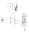
- FIG. 6 schematically shows a configuration example of a beam shaping device according to an embodiment of the present disclosure.
- a beam shaping device includes a phase modulation spatial light modulator 10 and a variable focus lens 21 as an optical device with a variable focal length f.
- the spatial light modulator 10 modulates the phase of the incident light L10 to display, as a display pattern, a phase pattern corresponding to the irradiation pattern irradiated onto the irradiation surface 50 (the surface to be processed, the object to be processed, etc.). .
- the spatial light modulator 10 forms, as an irradiation pattern, a hologram that forms one or more focused spot points P1 on the irradiated surface 50, for example.
- Light from a light source 30 having a certain degree of coherency enters the spatial light modulator 10 as incident light L10.
- the light source 30 may be a laser light source, or an LED (Light Emitting Diode) having a certain degree of spatial coherency.
- the spatial light modulator 10 can modulate the phase of the light from the light source 30, form an arbitrary shape by interference of the light, and modulate the direction in which the light travels.
- Spatial light modulator 10 has a two-dimensional pixel array.
- the spatial light modulator 10 may be of a reflective type or a transmissive type.
- the variable focus lens 21 focuses the light modulated by the spatial light modulator 10 toward the object, and forms a focused spot point P1 on the irradiated surface 50.
- the variable focus lens 21 may be a liquid crystal lens 22, a revolver type variable focus lens 24, a liquid lens 25, etc., as shown in modified examples (FIGS. 20 to 23) to be described later. Further, a phase modulation type spatial light modulator 23 may be provided separately from the spatial light modulator 10 that forms the irradiation pattern.
- the spatial frequency of the phase pattern displayed on the spatial light modulator 10 increases, the diffraction efficiency decreases.
- the spatial frequency of the phase pattern displayed on the spatial light modulator 10 is reduced, and a decrease in diffraction efficiency is suppressed. do.
- the spatial frequency of the phase pattern displayed on the spatial light modulator 10 can be reduced by leaving focus movement in the depth direction to the variable focus lens 21. Since the focus can be modulated by the variable focus lens 21, it is possible to control the combination of the range in which the condensed spot point P1 can be formed and the resolution.
- the focal plane is shifted by replacing the Fourier transform lens 20 with a fixed focal length with a variable focal length lens 21, compared to the configuration of the beam shaping device according to the comparative example (FIG. 5).
- This function can be realized by the variable focus lens 21.
- FIG. 7 schematically shows the effect of the variable focus lens 21 in the beam shaping device according to one embodiment.
- the focal length f can be modulated by the variable focus lens 21, it becomes possible to change the resolution of laser shaping and the range in which light can be irradiated.
- ⁇ is the wavelength of the incident light L10. The smaller the focal length f, the larger the NA becomes, so the spot diameter can be made smaller.
- x max f ⁇ tan ⁇ max
- ⁇ max is the maximum diffraction angle of the spatial light modulator 10. From this equation, it can be seen that the longer the focal length f, the larger the range that can be irradiated.
- the functions of the variable focus lens 21 from the viewpoint of processing applications include a function of modulating the position in the depth direction where a processing pattern is formed, and a function of modulating the size and resolution of the processing pattern.
- the processing proceeds while changing the focal length f of the variable focus lens 21 during the processing.
- the driving speed of the variable focus lens 21 is slower than the driving speed of the spatial light modulator 10. Therefore, by reducing the number of times the focal length f of the variable focus lens 21 is switched, it is possible to maximize the processing throughput.
- FIGS. 8 and 9 schematically show an example of a processing method using a beam shaping device according to an embodiment.
- throughput can be maximized by sequentially processing the machining points P2 at the same depth. That is, after processing all processing points P2 at a certain depth, the focal length f is sequentially changed and processing points P2 at different depths are sequentially processed, thereby changing the focal length of the variable focus lens 21. The number of times f is switched can be reduced and throughput can be maximized.
- FIG. 10 schematically shows a configuration example of a beam shaping device according to Modification 1.
- the focal position by the variable focus lens 21 is set in the vertical direction (depth direction) in a pattern (spot position control pattern) corresponding to the irradiation pattern. ) displays a pattern in which the focus movement pattern to be moved is superimposed.
- the spatial light modulator 10 superimposes a focus movement pattern to an extent that the diffraction efficiency does not decrease, thereby making it possible to shift the focus of the variable focus lens 21 in the depth direction. Furthermore, since the 0th order diffracted light on the irradiated surface 50 is defocused, it is possible to prevent the object from being processed at the focal point of the 0th order diffracted light. Further, for example, when the variable focus lens 21 is a revolver type variable focus lens 24 (FIG. 22), which will be described later, the variable focal length f becomes intermittently.
- the spatial light modulator 10 corresponds to the focal length f that is not included in the revolver type variable focus lens 24 as a phase pattern.
- FIG. 11 schematically shows a configuration example of a beam shaping device according to modification 2.
- a correction pattern for correcting aberrations caused by the variable focus lens 21 is added to the pattern corresponding to the irradiation pattern (spot position control pattern). Display the superimposed pattern.
- variable focus lens 21 has aberrations. If the aberration is known, by superimposing a correction pattern for correcting the aberration as a phase pattern, the aberration caused by the variable focus lens 21 can be canceled out by the correction pattern displayed on the spatial light modulator 10, It is possible to minimize the focused spot diameter. Thereby, it is possible to improve the resolution of the focused spot point P1.
- FIG. 12 schematically shows a configuration example of a beam shaping device according to modification 3.
- the base material of the irradiated surface 50 (object to be processed, etc.) is added to the pattern (spot position control pattern) corresponding to the irradiation pattern.
- a pattern in which a correction pattern for correcting aberrations caused by the image forming apparatus 40 is superimposed is displayed.
- FIG. 13 schematically shows a configuration example of a beam shaping device according to modification 4.
- the beam shaping device further includes a controller 60 that performs switching control of the phase pattern displayed on the spatial light modulator 10 and switching control of the focal length f of the variable focus lens 21.
- the controller 60 performs control to give priority to the switching control of the phase pattern displayed on the spatial light modulator 10 over the switching control of the focal length f in the variable focus lens 21.
- the driving speed of the spatial light modulator 10 is faster than the driving speed of the variable focus lens 21. switching time). For this reason, it is better to give priority to driving the spatial light modulator 10, change all the phase patterns of the spatial light modulator 10 at a certain focal length f, and then change the focal length f. It is possible to reduce this and maximize the overall throughput. This is effective when, for example, as shown in FIG. 13, there are a plurality of processing points P2 in the horizontal plane and in the depth direction of the base material 40, and the processing points P2 are hierarchical.
- phase patterns 1, 2,...n are displayed on the spatial light modulator 10 in each hierarchical plane. If necessary, perform switching control in the following order.
- FIG. 14 schematically shows a configuration example of a beam shaping device according to modification 5.
- the configuration of the beam shaping device according to Modification Example 5 is similar to the beam shaping device according to Modification Example 4, and includes switching control of the phase pattern displayed on the spatial light modulator 10 and switching control of the focal length f in the variable focus lens 21.
- the apparatus further includes a controller 60 that performs the following.
- the controller 60 performs control to give priority to the switching control of the phase pattern displayed on the spatial light modulator 10 over the switching control of the focal length f in the variable focus lens 21.
- FIG. 15 schematically shows a configuration example of a beam shaping device according to modification 6.
- the beam shaping device according to Modification 6 further includes an XY stage 70 as a horizontal movement device capable of moving the object in the horizontal direction (XY direction).
- the beam shaping device according to the sixth modification includes a controller that controls switching of the phase pattern displayed on the spatial light modulator 10, controls switching of the focal length f in the variable focus lens 21, and controls the movement of the XY stage 70. 60.
- the range in which the focal spot point P1 can be moved by the spatial light modulator 10 is limited to the maximum diffraction angle of the spatial light modulator 10.
- FIG. 16 schematically shows a configuration example of a beam shaping device according to modification 7.
- the beam shaping device according to Modification Example 7 like the beam shaping device according to Modification Example 6, further includes an XY stage 70 as a horizontal movement device capable of moving the object in the horizontal direction (XY direction). Further, the beam shaping device according to the seventh modification, like the beam shaping device according to the sixth modification, controls switching of the phase pattern displayed on the spatial light modulator 10 and controlling switching of the focal length f in the variable focus lens 21. and a controller 60 that controls the movement of the XY stage 70.
- the controller 60 controls switching of the phase pattern displayed on the spatial light modulator 10, switching of the focal length f of the variable focus lens 21, and movement control of the XY stage 70, in this order.
- the spatial light modulator 10, the variable focus lens 21, and the XY stage 70 have faster driving speeds in this order. f switching time) ⁇ driving time of the XY stage 70. Therefore, by prioritizing driving in the order of controlling the switching of the phase pattern displayed on the spatial light modulator 10, controlling the switching of the focal length f in the variable focus lens 21, and controlling the movement of the XY stage 70, the processing area can be improved while , it is possible to maximize the overall throughput. For example, as shown in FIG.
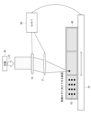
- FIG. 17 schematically shows a first configuration example of a beam shaping device according to modification 8.
- FIG. 18 schematically shows a second configuration example of a beam shaping device according to modification example 8.
- the beam shaping device according to Modification 8 further includes a vertical movement device capable of moving the object or the spatial light modulator 10 and the variable focus lens 21 in the vertical direction (Z-axis direction).
- the first configuration example shown in FIG. 17 shows an example including an XY stage 70 as a horizontal movement device capable of moving an object in the horizontal direction (XY direction) and a Z-axis drive device 71.
- the Z-axis drive device 71 is a vertical movement device that can move the spatial light modulator 10 and the variable focus lens 21 in the vertical direction (Z-axis direction).
- the switching control of the phase pattern displayed on the spatial light modulator 10 the switching control of the focal length f in the variable focus lens 21, the Z-axis drive device 71 and the XY stage
- the controller 60 further includes a controller 60 that controls the movement of the controller 70.
- an XYZ stage 72 is used as a horizontal movement device and a vertical movement device that can move the object in the horizontal direction (XY direction) and the vertical direction (Z axis direction).
- switching control of the phase pattern displayed on the spatial light modulator 10 switching control of the focal length f in the variable focus lens 21, and movement control of the XYZ stage 72 are performed.
- the apparatus further includes a controller 60 for performing the operations.
- the irradiable range and resolution of light also change at the same time, but there are some applications where it is problematic if the processing voxel size changes in the depth direction. Furthermore, when the spot is moved to a position significantly away from the focal length f of the variable focus lens 21, the diffraction efficiency decreases.
- a device that moves the optical system in the Z-axis direction or a Z-axis stage it is possible to change the distance between the spatial light modulator 10 and variable focus lens 21 and the workpiece. It becomes possible to process the workpiece while maintaining high diffraction efficiency without significantly changing the focal length f of the focusing lens 21. Further, it is possible to improve the range of light irradiation and the degree of freedom in resolution.
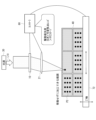
- FIG. 19 schematically shows a configuration example of a beam shaping device according to modification 9.
- the controller 60 controls switching of the phase pattern displayed on the spatial light modulator 10, controls switching of the focal length f in the variable focus lens 21, and controls vertical movement. Control may be prioritized in the order of device movement control.
- FIG. 19 shows a configuration example corresponding to the second configuration example of the beam shaping device according to Modification Example 8 shown in FIG. 18.
- the control when the vertical movement device is the XYZ stage 72 will be explained as an example.
- the spatial light modulator 10, the variable focus lens 21, and the XYZ stage 72 have faster driving speeds in this order. f switching time) ⁇ driving time of the XYZ stage 72. Therefore, by prioritizing driving in the order of controlling the switching of the phase pattern displayed on the spatial light modulator 10, controlling the switching of the focal length f in the variable focus lens 21, and controlling the movement of the XYZ stage 72, the machining area can be improved. , it is possible to maximize the overall throughput. For example, as shown in FIG.
- FIG. 20 schematically shows a configuration example of a beam shaping device according to Modification 10.
- the beam shaping device according to Modification 10 includes a liquid crystal lens 22 with a variable focal length f as an optical device with a variable focal length f.
- liquid crystal lens 22 as an optical device with a variable focal length f, it is possible to make the optical device with a variable focal length f thinner, the optical system lighter, and smaller. Further, continuous adjustment of the focal length f becomes possible.
- FIG. 21 schematically shows a configuration example of a beam shaping device according to modification 11.
- the beam shaping device includes a spatial light modulator 23 with a variable focal length f as an optical device with a variable focal length f.
- the spatial light modulator 10 displays, as a display pattern, a phase pattern that corresponds to the irradiation pattern that irradiates the object.
- the spatial light modulator 23 displays, as a phase pattern, a lens pattern for functioning as an optical device with a variable focal length f.
- the liquid crystal lens 22 (FIG. 20) and the spatial light modulator 23 have the same configuration in which the liquid crystal is driven by voltage, but in the liquid crystal lens 22, the electrode shape is, for example, circular in order to realize only the lens function. It has become.
- the spatial light modulator 23 is composed of, for example, a rectangular pixel array. Note that, as the configuration of the liquid crystal lens 22, there are a system combining Fresnel lenses, a system using cholesteric liquid crystal, etc., but the types of the liquid crystal lens 22 used as an optical device with a variable focal length f are not limited to these.
- FIG. 22 schematically shows a configuration example of a beam shaping device according to modification 12.
- the beam shaping device includes a revolver-type variable focal length lens 24 having a plurality of lenses with different focal lengths f, as an optical device with a variable focal length f.
- the revolver type variable focal length lens 24 As an optical device with variable focal length f, it becomes possible to employ a refractive lens with accumulated design know-how, and it becomes easy to suppress aberrations.
- focus adjustment is discrete, but when it is desired to focus light on a position of focal length f that is not included in the revolver, a spatial light modulator is used as a phase pattern.
- a spatial light modulator is used as a phase pattern.
- FIG. 23 schematically shows a configuration example of a beam shaping device according to modification 13.
- the beam shaping device includes a liquid lens 25 with a variable focal length f as an optical device with a variable focal length f.
- liquid lens 25 As an optical device with a variable focal length f, it becomes possible to continuously adjust the focal length f.
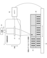
- FIG. 24 shows an example of application of the beam shaping device according to one embodiment to a processing device.
- FIG. 24 shows a configuration example in which the beam shaping device according to modification 8 shown in FIG. 17 is used as the beam shaping device.
- the beam shaping device is applicable to a processing device such as a laser soldering device, for example.
- FIG. 24 shows an example in which parts 81 of various sizes and shapes are soldered onto an electronic circuit board 80.
- a beam shaping device constitutes a laser soldering device that combines the spatial light modulator 10 and the variable focus lens 21.
- the size of the parts 81 changes significantly from several tens of micrometers to several millimeters, and the required resolution and light irradiation range vary depending on the type of parts 81 to be soldered.
- a single focus (fixed focus) lens FIG. 5
- the spatial light modulator 10 displays a phase pattern according to the irradiation pattern irradiated onto the target object, and the optical The device focuses the light modulated by the spatial light modulator 10 toward an object. This makes it possible to modulate the irradiation pattern over a wide range and with high precision.
- the focal spot size and the degree of freedom of the irradiation range are improved, meeting the needs of various irradiation shapes. You will be able to do it.
- the focal length f of the Fourier transform lens variable the focal length f can be made longer in situations where a wide range of steering is required while maintaining diffraction efficiency. In situations where high resolution is required, this can be achieved by shortening the focal length f.
- the present technology can also take the following configuration.
- a spatial light modulator displays a phase pattern corresponding to an irradiation pattern irradiated onto a target object
- an optical device with a variable focal length displays a phase pattern that is modulated by the spatial light modulator. Focuses light onto an object. This makes it possible to modulate the irradiation pattern over a wide range and with high precision.
- a phase modulation spatial light modulator that displays a phase pattern according to the irradiation pattern applied to the target object;
- a beam shaping device comprising: an optical device with a variable focal length that focuses the light modulated by the spatial light modulator toward the target object.
- the spatial light modulator displays, as the phase pattern, a pattern in which a pattern corresponding to the irradiation pattern is superimposed with a focus movement pattern that moves the focus position of the optical device in the vertical direction. beam shaping device.
- the spatial light modulator displays, as the phase pattern, a pattern in which a correction pattern for correcting aberrations caused by the optical device is superimposed on a pattern corresponding to the irradiation pattern. beam shaping device.
- the spatial light modulator displays, as the phase pattern, a pattern in which a correction pattern for correcting aberrations caused by the base material of the object is superimposed on a pattern corresponding to the irradiation pattern.
- the beam shaping device according to any one of the above. (5) further comprising a controller that performs switching control of the phase pattern displayed on the spatial light modulator and switching control of the focal length in the optical device, The controller performs control to give priority to switching control of the phase pattern displayed on the spatial light modulator over control of switching the focal length in the optical device.
- Beam shaping device described in. (6) The beam shaping device according to any one of (1) to (5) above, further comprising a horizontal movement device capable of horizontally moving the object.
- (7) further comprising a controller that performs switching control of the phase pattern displayed on the spatial light modulator, switching control of the focal length in the optical device, and movement control of the horizontal movement device, The controller prioritizes control in the order of switching control of the phase pattern displayed on the spatial light modulator, switching control of the focal length in the optical device, and movement control of the horizontal movement device.
- Beam shaping device The beam shaping device according to any one of (1) to (7) above, further comprising a vertical movement device capable of vertically moving the object, or the spatial light modulator and the optical device. .
- (9) further comprising a controller that performs switching control of the phase pattern displayed on the spatial light modulator, switching control of the focal length in the optical device, and movement control of the vertical movement device, The controller prioritizes control in the order of switching control of the phase pattern displayed on the spatial light modulator, switching control of the focal length in the optical device, and movement control of the vertical movement device.
- Beam shaping device (10) The beam shaping device according to any one of (1) to (9) above, wherein the optical device is a liquid crystal lens with a variable focal length. (11) The beam shaping device according to any one of (1) to (9) above, wherein the optical device is a spatial light modulator with a variable focal length.
- the beam shaping device according to any one of (1) to (9) above, wherein the optical device is a revolver type variable focal length lens.
- the optical device is a liquid lens with a variable focal length.
- a phase modulation spatial light modulator that displays a phase pattern according to the irradiation pattern applied to the object to be processed;
- a processing device comprising: an optical device with a variable focal length that focuses light modulated by the spatial light modulator toward the target object.
Abstract
Un dispositif de mise en forme de faisceau selon un mode de réalisation de la présente divulgation permet la modulation d'un motif d'irradiation avec une précision élevée sur une large plage. Le dispositif de mise en forme de faisceau selon la présente divulgation comprend : un modulateur spatial de lumière à modulation de phase (10) qui affiche un motif de phase correspondant à un motif d'irradiation avec lequel un objet (50) doit être irradié; et un dispositif optique (21) qui a une distance focale variable et condense la lumière modulée par le modulateur spatial de lumière sur l'objet.
Applications Claiming Priority (2)
| Application Number | Priority Date | Filing Date | Title |
|---|---|---|---|
| JP2022084837 | 2022-05-24 | ||
| JP2022-084837 | 2022-05-24 |
Publications (1)
| Publication Number | Publication Date |
|---|---|
| WO2023228548A1 true WO2023228548A1 (fr) | 2023-11-30 |
Family
ID=88919050
Family Applications (1)
| Application Number | Title | Priority Date | Filing Date |
|---|---|---|---|
| PCT/JP2023/012269 WO2023228548A1 (fr) | 2022-05-24 | 2023-03-27 | Dispositif de mise en forme de faisceau et dispositif de traitement |
Country Status (1)
| Country | Link |
|---|---|
| WO (1) | WO2023228548A1 (fr) |
Citations (7)
| Publication number | Priority date | Publication date | Assignee | Title |
|---|---|---|---|---|
| JP2011051011A (ja) * | 2009-08-03 | 2011-03-17 | Hamamatsu Photonics Kk | レーザ加工方法及び半導体装置の製造方法 |
| JP2013043204A (ja) * | 2011-08-24 | 2013-03-04 | Hamamatsu Photonics Kk | レーザ加工方法 |
| WO2013157606A1 (fr) * | 2012-04-20 | 2013-10-24 | 浜松ホトニクス株式会社 | Dilatateur de faisceau |
| JP2015024428A (ja) * | 2013-07-26 | 2015-02-05 | 住友大阪セメント株式会社 | 加工装置 |
| JP2016055319A (ja) * | 2014-09-10 | 2016-04-21 | 浜松ホトニクス株式会社 | 光照射装置および光照射方法 |
| CN108161250A (zh) * | 2018-01-30 | 2018-06-15 | 苏州德龙激光股份有限公司 | 多焦点动态分布激光加工脆性透明材料的方法及装置 |
| JP2019512397A (ja) * | 2016-03-17 | 2019-05-16 | エレクトロ サイエンティフィック インダストリーズ インコーポレーテッド | レーザ加工システムにおける像平面の配置 |
-
2023
- 2023-03-27 WO PCT/JP2023/012269 patent/WO2023228548A1/fr unknown
Patent Citations (7)
| Publication number | Priority date | Publication date | Assignee | Title |
|---|---|---|---|---|
| JP2011051011A (ja) * | 2009-08-03 | 2011-03-17 | Hamamatsu Photonics Kk | レーザ加工方法及び半導体装置の製造方法 |
| JP2013043204A (ja) * | 2011-08-24 | 2013-03-04 | Hamamatsu Photonics Kk | レーザ加工方法 |
| WO2013157606A1 (fr) * | 2012-04-20 | 2013-10-24 | 浜松ホトニクス株式会社 | Dilatateur de faisceau |
| JP2015024428A (ja) * | 2013-07-26 | 2015-02-05 | 住友大阪セメント株式会社 | 加工装置 |
| JP2016055319A (ja) * | 2014-09-10 | 2016-04-21 | 浜松ホトニクス株式会社 | 光照射装置および光照射方法 |
| JP2019512397A (ja) * | 2016-03-17 | 2019-05-16 | エレクトロ サイエンティフィック インダストリーズ インコーポレーテッド | レーザ加工システムにおける像平面の配置 |
| CN108161250A (zh) * | 2018-01-30 | 2018-06-15 | 苏州德龙激光股份有限公司 | 多焦点动态分布激光加工脆性透明材料的方法及装置 |
Similar Documents
| Publication | Publication Date | Title |
|---|---|---|
| JP6258787B2 (ja) | レーザ加工装置及びレーザ加工方法 | |
| US7157661B2 (en) | Method and apparatus for laser machining | |
| JP6272145B2 (ja) | レーザ加工装置及びレーザ加工方法 | |
| US10228552B2 (en) | Structured illuminating microscopy and structured illuminating observation method | |
| KR102250704B1 (ko) | 레이저 가공 장치 및 레이저 가공 방법 | |
| JP5836415B2 (ja) | レーザ加工方法及び半導体装置の製造方法 | |
| CN111014947A (zh) | 基于空间光调制器和扫描振镜的高速激光加工装置和方法 | |
| JP4729883B2 (ja) | 基板の加工方法、マイクロレンズシートの製造方法、透過型スクリーン、プロジェクタ、表示装置並びに基板の加工装置 | |
| WO2011016296A1 (fr) | Procédé d'usinage au laser | |
| US9146393B2 (en) | Structured illumination apparatus, structured illumination microscopy, and structured illumination method | |
| KR20220079949A (ko) | 세그먼트화된 빔 정형 요소 및 레이저 가공 시스템 | |
| US11465235B2 (en) | Laser light irradiating device | |
| WO2023228548A1 (fr) | Dispositif de mise en forme de faisceau et dispositif de traitement | |
| EP2683516B1 (fr) | Système et procédé de fabrication laser | |
| JPS63249125A (ja) | 可変焦点光学系 | |
| CN111913313A (zh) | 一种参数可调轴向余弦结构光产生装置及方法 | |
| WO2020009079A1 (fr) | Dispositif d'usinage au laser | |
| WO2022265046A1 (fr) | Dispositif de traitement laser et procédé de traitement laser | |
| CN215698845U (zh) | 利用空间光调制器的激光加工装置 | |
| JP2010020098A (ja) | 光制御装置および光制御方法 | |
| JP3712626B2 (ja) | 集光線位置微調装置 |
Legal Events
| Date | Code | Title | Description |
|---|---|---|---|
| 121 | Ep: the epo has been informed by wipo that ep was designated in this application |
Ref document number: 23811427 Country of ref document: EP Kind code of ref document: A1 |