WO2023228401A1 - 加工システム - Google Patents
加工システム Download PDFInfo
- Publication number
- WO2023228401A1 WO2023228401A1 PCT/JP2022/021729 JP2022021729W WO2023228401A1 WO 2023228401 A1 WO2023228401 A1 WO 2023228401A1 JP 2022021729 W JP2022021729 W JP 2022021729W WO 2023228401 A1 WO2023228401 A1 WO 2023228401A1
- Authority
- WO
- WIPO (PCT)
- Prior art keywords
- processing
- optical system
- light
- irradiation
- measurement
- Prior art date
- Legal status (The legal status is an assumption and is not a legal conclusion. Google has not performed a legal analysis and makes no representation as to the accuracy of the status listed.)
- Ceased
Links
Images


Classifications
-
- B—PERFORMING OPERATIONS; TRANSPORTING
- B23—MACHINE TOOLS; METAL-WORKING NOT OTHERWISE PROVIDED FOR
- B23K—SOLDERING OR UNSOLDERING; WELDING; CLADDING OR PLATING BY SOLDERING OR WELDING; CUTTING BY APPLYING HEAT LOCALLY, e.g. FLAME CUTTING; WORKING BY LASER BEAM
- B23K26/00—Working by laser beam, e.g. welding, cutting or boring
- B23K26/08—Devices involving relative movement between laser beam and workpiece
- B23K26/082—Scanning systems, i.e. devices involving movement of the laser beam relative to the laser head
-
- B—PERFORMING OPERATIONS; TRANSPORTING
- B23—MACHINE TOOLS; METAL-WORKING NOT OTHERWISE PROVIDED FOR
- B23K—SOLDERING OR UNSOLDERING; WELDING; CLADDING OR PLATING BY SOLDERING OR WELDING; CUTTING BY APPLYING HEAT LOCALLY, e.g. FLAME CUTTING; WORKING BY LASER BEAM
- B23K26/00—Working by laser beam, e.g. welding, cutting or boring
- B23K26/02—Positioning or observing the workpiece, e.g. with respect to the point of impact; Aligning, aiming or focusing the laser beam
- B23K26/03—Observing, e.g. monitoring, the workpiece
- B23K26/032—Observing, e.g. monitoring, the workpiece using optical means
-
- B—PERFORMING OPERATIONS; TRANSPORTING
- B23—MACHINE TOOLS; METAL-WORKING NOT OTHERWISE PROVIDED FOR
- B23K—SOLDERING OR UNSOLDERING; WELDING; CLADDING OR PLATING BY SOLDERING OR WELDING; CUTTING BY APPLYING HEAT LOCALLY, e.g. FLAME CUTTING; WORKING BY LASER BEAM
- B23K26/00—Working by laser beam, e.g. welding, cutting or boring
- B23K26/02—Positioning or observing the workpiece, e.g. with respect to the point of impact; Aligning, aiming or focusing the laser beam
- B23K26/06—Shaping the laser beam, e.g. by masks or multi-focusing
- B23K26/064—Shaping the laser beam, e.g. by masks or multi-focusing by means of optical elements, e.g. lenses, mirrors or prisms
- B23K26/0648—Shaping the laser beam, e.g. by masks or multi-focusing by means of optical elements, e.g. lenses, mirrors or prisms comprising lenses
-
- B—PERFORMING OPERATIONS; TRANSPORTING
- B23—MACHINE TOOLS; METAL-WORKING NOT OTHERWISE PROVIDED FOR
- B23K—SOLDERING OR UNSOLDERING; WELDING; CLADDING OR PLATING BY SOLDERING OR WELDING; CUTTING BY APPLYING HEAT LOCALLY, e.g. FLAME CUTTING; WORKING BY LASER BEAM
- B23K26/00—Working by laser beam, e.g. welding, cutting or boring
- B23K26/02—Positioning or observing the workpiece, e.g. with respect to the point of impact; Aligning, aiming or focusing the laser beam
- B23K26/06—Shaping the laser beam, e.g. by masks or multi-focusing
- B23K26/0665—Shaping the laser beam, e.g. by masks or multi-focusing by beam condensation on the workpiece, e.g. for focusing
-
- B—PERFORMING OPERATIONS; TRANSPORTING
- B23—MACHINE TOOLS; METAL-WORKING NOT OTHERWISE PROVIDED FOR
- B23K—SOLDERING OR UNSOLDERING; WELDING; CLADDING OR PLATING BY SOLDERING OR WELDING; CUTTING BY APPLYING HEAT LOCALLY, e.g. FLAME CUTTING; WORKING BY LASER BEAM
- B23K26/00—Working by laser beam, e.g. welding, cutting or boring
- B23K26/12—Working by laser beam, e.g. welding, cutting or boring in a special environment or atmosphere, e.g. in an enclosure
- B23K26/1224—Working by laser beam, e.g. welding, cutting or boring in a special environment or atmosphere, e.g. in an enclosure in vacuum
-
- B—PERFORMING OPERATIONS; TRANSPORTING
- B23—MACHINE TOOLS; METAL-WORKING NOT OTHERWISE PROVIDED FOR
- B23K—SOLDERING OR UNSOLDERING; WELDING; CLADDING OR PLATING BY SOLDERING OR WELDING; CUTTING BY APPLYING HEAT LOCALLY, e.g. FLAME CUTTING; WORKING BY LASER BEAM
- B23K26/00—Working by laser beam, e.g. welding, cutting or boring
- B23K26/12—Working by laser beam, e.g. welding, cutting or boring in a special environment or atmosphere, e.g. in an enclosure
- B23K26/123—Working by laser beam, e.g. welding, cutting or boring in a special environment or atmosphere, e.g. in an enclosure in an atmosphere of particular gases
-
- B—PERFORMING OPERATIONS; TRANSPORTING
- B23—MACHINE TOOLS; METAL-WORKING NOT OTHERWISE PROVIDED FOR
- B23K—SOLDERING OR UNSOLDERING; WELDING; CLADDING OR PLATING BY SOLDERING OR WELDING; CUTTING BY APPLYING HEAT LOCALLY, e.g. FLAME CUTTING; WORKING BY LASER BEAM
- B23K26/00—Working by laser beam, e.g. welding, cutting or boring
- B23K26/12—Working by laser beam, e.g. welding, cutting or boring in a special environment or atmosphere, e.g. in an enclosure
- B23K26/127—Working by laser beam, e.g. welding, cutting or boring in a special environment or atmosphere, e.g. in an enclosure in an enclosure
-
- B—PERFORMING OPERATIONS; TRANSPORTING
- B23—MACHINE TOOLS; METAL-WORKING NOT OTHERWISE PROVIDED FOR
- B23K—SOLDERING OR UNSOLDERING; WELDING; CLADDING OR PLATING BY SOLDERING OR WELDING; CUTTING BY APPLYING HEAT LOCALLY, e.g. FLAME CUTTING; WORKING BY LASER BEAM
- B23K26/00—Working by laser beam, e.g. welding, cutting or boring
- B23K26/70—Auxiliary operations or equipment
-
- B—PERFORMING OPERATIONS; TRANSPORTING
- B23—MACHINE TOOLS; METAL-WORKING NOT OTHERWISE PROVIDED FOR
- B23K—SOLDERING OR UNSOLDERING; WELDING; CLADDING OR PLATING BY SOLDERING OR WELDING; CUTTING BY APPLYING HEAT LOCALLY, e.g. FLAME CUTTING; WORKING BY LASER BEAM
- B23K2101/00—Articles made by soldering, welding or cutting
- B23K2101/001—Turbines
Definitions
- the present invention relates, for example, to the technical field of processing systems capable of processing objects.
- Patent Document 1 describes a processing system that processes an object by irradiating the object with laser light. This type of processing system is required to process objects appropriately.
- an irradiation optical system capable of irradiating the object with an energy beam for processing the object
- a mounting device capable of mounting the object on a mounting surface, and the mounting device.
- a first changing device capable of changing at least one of a positional relationship and a posture relationship between the placed object and the irradiation optical system; and a light receiving device capable of receiving the energy beam emitted from the irradiation optical system.
- a second changing device capable of changing the positional relationship between the light receiving device and the irradiation optical system, and a control device, and under the control of the control device, the second changing device changes the light receiving device.
- a processing system is provided that is repositioned from a second position different from the first position to a first position capable of receiving the energy beam.
- the object it is possible to irradiate the object with a processing beam for processing the object, and to irradiate the object with a measurement beam for measuring the object, and at least an irradiation optical system including an objective optical system; a light receiving device capable of receiving the processing beam and the measurement beam emitted from the irradiation optical system; a position changing device capable of changing at least one of the irradiation position of the measurement beam; and a control device, the control device configured to change the reception result of the processed beam by the light receiving device and the reception of the measurement beam by the light receiving device.
- a processing system is provided that controls the position changing device based on the results.
- a deflection optical system capable of deflecting an energy beam for processing or measuring an object to change the irradiation position of the energy beam on the object;
- the light receiving device capable of receiving the energy beam emitted from the irradiation optical system, and the deflection optical system
- the light receiving device includes a position changing device that can change the irradiation position of the energy beam on the top, and a control device that controls the position changing device based on the result of reception of the energy beam by the light receiving device, the light receiving device a beam passing member formed with a plurality of passing regions through which the energy beam emitted from the irradiation optical system can pass; and a light receiving section capable of receiving each of the energy beams that have passed through each of the plurality of passing regions.
- the deflection optical system deflects the energy beam so that the energy beam scans the plurality of passing regions along one direction along the surface of the beam passing member;
- a processing system is provided that controls the position changing device based on a result of reception of the energy beam by a light receiving device.
- an exit optical system including a position adjustment optical system; the exit optical system is capable of irradiating the object with the energy beam emitted from the exit optical system; and the exit optical system is removable from the exit optical system; identifying a plurality of irradiation optical systems including an objective optical system, an exchange device capable of replacing the irradiation optical system attached to the emission optical system, and the type of the irradiation optical system attached to the emission optical system; One of the plurality of light collection position adjustment optical systems is selected based on the identified type, and the selected one light collection position adjustment optical system is positioned in the optical path of the energy beam.
- a processing system is provided, comprising: a control device that moves the first focusing position adjusting optical system so as to move the first focusing position adjusting optical system.
- an irradiation optical system capable of irradiating an energy beam onto an object; a first changing device capable of changing at least one of a positional relationship and an attitude relationship between the object and the irradiation optical system; A light receiving device capable of receiving the energy beam emitted from the irradiation optical system, a second changing device capable of changing a positional relationship between the light receiving device and the irradiation optical system, and a control device, the control device A processing system is provided in which, under the control of the second changing device, the light receiving device is changed in position from a second position different from the first position to a first position where the light receiving device can receive the energy beam.
- an irradiation optical system capable of irradiating an object with a first beam and a second beam different from the first beam; a light receiving device capable of receiving the first beam and the second beam; and changing at least one of the irradiation position of the first beam on the object and the irradiation position of the second beam on the object. and a control device, the control device controlling the position change device based on the light reception result of the first beam by the light receiving device and the light reception result of the second beam by the light receiving device.
- a processing system is provided for controlling.
- a deflection optical system capable of deflecting an energy beam to change the irradiation position of the energy beam on an object; and a deflection optical system capable of irradiating the object with the energy beam emitted from the deflection optical system.
- the control device includes a beam passing member formed with a plurality of passing regions through which the energy beam can pass, and a light receiving section capable of receiving each of the energy beams that have passed through each of the plurality of passing regions, and the control device A processing system is provided that controls the position changing device based on a result of reception of the energy beam by the device.
- the injection optical system includes a plurality of focusing position adjusting optical systems capable of emitting an energy beam, adjusting a focusing position of the energy beam, and having different focal lengths.
- a plurality of irradiation systems capable of irradiating the object with the energy beam emitted from the emission optical system, detachable from the emission optical system, and including at least an objective optical system;
- One of the plurality of light focusing position adjusting optical systems is selected, and the one light focusing position is adjusted so that the selected one light focusing position adjusting optical system is located in the optical path of the energy beam.
- a processing system is provided that includes a control device that moves a position adjustment optical system.
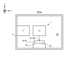
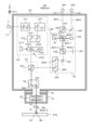
- FIG. 1 is a cross-sectional view schematically showing an example of the configuration of a processing system according to the first embodiment.
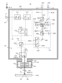
- FIG. 2 is a block diagram showing an example of the configuration of the processing system in the first embodiment.
- FIG. 3 is a sectional view showing the configuration of the processing head in the first embodiment.
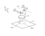
- FIG. 4 is a perspective view showing a processing shot area.
- FIG. 5 is a perspective view showing the measurement shot area.
- FIG. 6 is a sectional view showing an example of the configuration of a mounting adapter used to attach the irradiation optical system to the exit optical system.
- FIGS. 7(a) to 7(c) is a cross-sectional view showing the process of attaching the irradiation optical system to the exit optical system.
- FIG. 7(a) to 7(c) is a cross-sectional view showing the process of attaching the irradiation optical system to the exit optical system.
- FIG. 8 is a cross-sectional view conceptually showing an example of the configuration of the head exchange device.
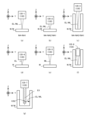
- FIGS. 9(a) to 9(g) is a cross-sectional view showing an example of an irradiation optical system.
- FIG. 10 is a block diagram showing an example of the configuration of a processing system in the second embodiment.
- FIG. 11(a) is a sectional view showing the calibration position where the optical measurement device is located when the calibration operation is performed
- FIG. 11(b) is a sectional view showing the calibration position where the optical measurement device is located when the calibration operation is not performed.
- FIG. 3 is a cross-sectional view showing a non-calibration position where is located.
- FIG. 12 is a sectional view showing the configuration of the optical measurement device.
- FIG. 13 is a plan view showing a search mark formed by a light passage area.
- FIG. 14 is a plan view showing a beam passing member on which a plurality of search marks are formed.
- FIG. 15 is a plan view showing a beam passing member on which a plurality of search marks are formed.
- FIG. 16 is a plan view showing a plurality of search marks irradiated with processing light.
- FIG. 17 shows light reception information output by the light receiving element.
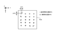
- FIG. 18 is a plan view showing the reference irradiation position of the processing light and the actual irradiation position of the processing light within the processing shot area.
- FIGS. 19(a) to 19(c) shows light reception information output by the light receiving element.
- FIG. 19(a) to 19(c) shows light reception information output by the light receiving element.
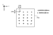
- FIG. 20 is a plan view showing the reference irradiation position of the measurement light and the actual irradiation position of the measurement light within the measurement shot area.
- FIG. 21 is a plan view showing the actual irradiation position of the processing light and the actual irradiation position of the measurement light in the processing shot area and the measurement shot area.
- FIGS. 22(a) to 22(c) shows light reception information output by the light receiving element.
- FIG. 23 is a sectional view showing the configuration of a processing head in the third embodiment.
- FIG. 24 is a sectional view showing the configuration of a processing head in the fourth embodiment.
- FIG. 25 is a sectional view showing the configuration of a processing head in the fifth embodiment.
- FIG. 26 is a cross-sectional view showing the configuration of a processing head in the fifth embodiment.
- each of the X-axis direction and the Y-axis direction is a horizontal direction (that is, a predetermined direction within a horizontal plane), and the Z-axis direction is a vertical direction (that is, a direction perpendicular to the horizontal plane). (and substantially in the vertical direction).
- the rotation directions (in other words, the tilt directions) around the X-axis, Y-axis, and Z-axis are referred to as the ⁇ X direction, the ⁇ Y direction, and the ⁇ Z direction, respectively.
- the Z-axis direction may be the direction of gravity.
- the XY plane may be set in the horizontal direction.
- processing system SYS Processing system SYS of the first embodiment
- processing system SYSa Processing system SYS in the first embodiment
- processing system SYSa the processing system SYS in the first embodiment
- FIG. 1 is a cross-sectional view schematically showing an example of the configuration of the processing system SYSa in the first embodiment.
- FIG. 2 is a block diagram showing an example of the configuration of the processing system SYSa in the first embodiment.
- the processing system SYSa includes a processing unit 1 and a control unit 2.
- the processing unit 1 may be called a processing device, and the control unit 2 may be called a control device.
- At least a portion of the processing unit 1 may be accommodated in the internal space SP of the housing 3.
- the internal space SP of the housing 3 may be purged with a purge gas (that is, gas) such as nitrogen gas, or may not be purged with a purge gas.
- the internal space SP of the housing 3 may or may not be evacuated.
- the processing unit 1 may not be housed in the internal space SP of the housing 3.
- a local space surrounding only a part of the processing unit 1 may be purged with a purge gas or may be evacuated.
- the processing unit 1 is capable of processing a workpiece W, which is a workpiece (which may also be referred to as a base material), under the control of the control unit 2.
- the workpiece W may be made of metal, an alloy (such as duralumin), a semiconductor (such as silicon), a resin, or a CFRP. It may be a composite material such as (Carbon Fiber Reinforced Plastic), a paint (as an example, a paint layer applied to a base material), a glass, or any other material. It may also be an object made of material.
- the processing unit 1 irradiates the workpiece W with processing light EL in order to process the workpiece W.
- the processing light EL may be any type of light as long as the workpiece W can be processed by being irradiated onto the workpiece W. In the first embodiment, the description will be given using an example in which the processing light EL is a laser beam, but the processing light EL may be a different type of light from the laser beam.
- the wavelength of the processing light EL may be any wavelength as long as the workpiece W can be processed by being irradiated with the processing light EL.
- the processing light EL may be visible light or invisible light (for example, at least one of infrared light, ultraviolet light, extreme ultraviolet light, etc.).
- the processing light EL may include pulsed light. Alternatively, the processing light EL may not include pulsed light. In other words, the processing light EL may be continuous light. Note that since the light is an example of an energy beam, the processing light EL may also be referred to as a processing beam.
- the processing unit 1 may perform additional processing on the workpiece W. That is, the processing unit 1 may perform additional processing to form a shaped object on the workpiece W.
- the processing unit 1 may perform removal processing on the workpiece W. That is, the processing unit 1 may perform removal processing to remove a part of the workpiece W.
- the processing unit 1 may perform marking processing to form a desired mark on the surface of the workpiece W.
- the processing unit 1 may perform peening processing to change the surface characteristics of the workpiece W.
- the processing unit 1 may perform a peeling process to peel off the surface of the workpiece W.
- the processing unit 1 may perform welding processing to join one work W and another work W.
- the processing unit 1 may perform cutting processing to cut the workpiece W.
- the processing unit 1 may perform planar processing (in other words, remelting processing) for making the surface of the workpiece W close to a flat surface by melting the surface of the workpiece W and solidifying the melted surface.
- the processing unit 1 may form a desired structure on the surface of the workpiece W by processing the workpiece W. However, the processing unit 1 may perform processing different from the processing for forming a desired structure on the surface of the workpiece W.
- the riblet structure may include a structure capable of reducing resistance (particularly, at least one of frictional resistance and turbulent flow frictional resistance) on the surface of the work W against fluid. For this reason, the riblet structure may be formed on the workpiece W having a member installed (in other words, located) in the fluid.
- the term "fluid” used herein means a medium (for example, at least one of gas and liquid) flowing toward the surface of the workpiece W. For example, if the surface of the workpiece W moves relative to the medium while the medium itself is stationary, this medium may be referred to as a fluid.
- the state in which the medium is stationary may mean a state in which the medium is not moving relative to a predetermined reference object (for example, the ground surface).
- An example of the workpiece W on which the riblet structure is formed is at least one of an aircraft, a windmill, an engine turbine, and a power generation turbine.
- the workpiece W becomes easier to move relative to the fluid. Therefore, the resistance that prevents movement of the workpiece W relative to the fluid is reduced, leading to energy savings.
- the resistance that impedes movement (typically, rotation) of the windmill is reduced, so that the efficiency of the windmill can be improved.
- the workpiece W is an engine turbine (for example, at least a part of the engine turbine)
- the resistance that prevents movement (typically, rotation) of the engine turbine is reduced; This leads to higher efficiency or energy saving of engine turbines.
- the workpiece W is a power generation turbine (for example, at least a part of the power generation turbine)
- the resistance that prevents movement (typically, rotation) of the power generation turbine is reduced; This leads to higher efficiency of power generation turbines (in other words, improved power generation efficiency).
- Processing Unit 1 is committed to achieving Goal 13 of the Sustainable Development Goals (SDGs) led by the United Nations: ⁇ Take urgent action to combat climate change and its impacts.'' It has the potential to contribute to ⁇ 13.2.2 Reduction of Total Greenhouse Gas Emissions per Year'', which is one of the goals set forth in ⁇ and its impact''.
- SDGs Sustainable Development Goals
- the processing unit 1 is further capable of measuring the measurement object M under the control of the control unit 2.
- the processing unit 1 irradiates the measurement object M with measurement light ML for measuring the measurement object M, in order to measure the measurement object M.
- the processing unit 1 irradiates the measurement object M with the measurement light ML, and detects at least a portion of the return light RL that returns from the measurement object M irradiated with the measurement light ML ( In other words, the object M to be measured is measured by receiving light.
- the light that returns from the measurement object M that has been irradiated with the measurement light ML is light from the measurement object M that is generated by the irradiation of the measurement light ML.
- the measurement light ML may be any type of light as long as the measurement target M can be measured by being irradiated onto the measurement target M.
- the measurement light ML is a laser light.
- the measurement light ML may be a different type of light from laser light.
- the wavelength of the measurement light ML may be any wavelength as long as the measurement target M can be measured by being irradiated onto the measurement target M.
- the measurement light ML may be visible light or invisible light (for example, at least one of infrared light, ultraviolet light, extreme ultraviolet light, etc.).
- the measurement light ML may include pulsed light (for example, pulsed light whose emission time is picoseconds or less). Alternatively, the measurement light ML does not need to include pulsed light. In other words, the measurement light ML may be continuous light. Note that since light is an example of an energy beam, the measurement light ML may also be referred to as a measurement beam.
- the processing unit 1 may be able to measure the characteristics of the measurement target M using the measurement light ML.
- the characteristics of the measurement target M include, for example, the position of the measurement target M, the shape of the measurement target M, the reflectance of the measurement target M, the transmittance of the measurement target M, the temperature of the measurement target M, and the measurement It may include at least one of the surface roughness of the object M.
- the processing unit 1 measures at least the position of the measurement target object M.
- the position of the measurement target M may include the position of the surface of the measurement target M.
- the position of the surface of the measurement target M may include the position of at least a portion of the surface of the measurement target M.
- the position of the measurement object M may mean the position (that is, relative position) of the measurement object M with respect to the processing head 13. That is, the position of the measurement object M may mean the position of the measurement object M in the measurement coordinate system with the processing head 13 as a reference.
- the operation of measuring the position of the measurement object M may include the operation of measuring the shape of the measurement object M. This is because the shape of the measurement target M can be calculated from the position of the measurement target M.
- the measurement object M may include, for example, a workpiece W that is processed by the processing unit 1.
- the measurement object M may include, for example, any object placed on a stage 15, which will be described later.
- the measurement object M may include a stage 15, for example.
- the measurement object M may include, for example, an optical measurement device 18b used in a calibration operation described later in the second embodiment.
- the processing unit 1 includes a processing light source 11, a measurement light source 12, a processing head 13, a head drive system 141, a position measuring device 142, and a stage 15. , a stage drive system 161 , a position measurement device 162 , and a head exchange device 17 .
- the processing light source 11 generates processing light EL.
- the processing light source 11 may include, for example, a laser diode.
- the processing light source 11 may be a light source capable of pulse oscillation. In this case, the processing light source 11 can generate pulsed light as the processing light EL.
- the processing light source 11 may be a CW light source that generates CW (continuous wave).
- the measurement light source 12 generates measurement light ML.
- the measurement light source 12 may include, for example, a laser diode.
- the measurement light source 12 may be a light source capable of pulse oscillation.
- the measurement light source 12 can generate pulsed light as the processing light EL.
- the measurement light source 12 may be a CW light source that generates CW (continuous wave).
- the processing head 13 irradiates the workpiece W with the processing light EL generated by the processing light source 11 and irradiates the measurement object M with the measurement light ML generated by the measurement light source 12.
- the machining head 13 includes a machining optical system 131, a measurement optical system 132, a combining optical system 133, and a deflection optical system. 134 and an irradiation optical system 135.
- the processing head 13 irradiates the workpiece W with processing light EL via a processing optical system 131, a combining optical system 133, a deflection optical system 134, and an irradiation optical system 135.
- the processing head 13 irradiates the measurement object M with the measurement light ML via the measurement optical system 132, the synthesis optical system 133, the deflection optical system 134, and the irradiation optical system 135. Note that the details of the configuration of the processing head 13 will be described in detail later with reference to FIG. 3.
- the head drive system 141 moves the processing head 13. That is, the head drive system 141 moves the position of the processing head 13. For this reason, the head drive system 141 may be referred to as a moving device.
- the head drive system 141 may move the processing head 13 (that is, linearly move) along a movement axis along at least one of the X-axis direction, the Y-axis direction, and the Z-axis direction, for example.
- the head drive system 141 moves the processing head 13 along at least one of the ⁇ X direction, the ⁇ Y direction, and the ⁇ Z direction, in addition to or instead of at least one of the X-axis direction, Y-axis direction, and Z-axis direction. may be moved.
- the head drive system 141 has a rotation axis along the X-axis direction (namely, the A-axis), a rotation axis along the Y-axis direction (namely, the B-axis), and a rotation axis along the Z-axis direction (namely, the C-axis).
- the processing head 13 may be rotated (that is, rotationally moved) around at least one of the axes).
- the processing unit 1 may process the workpiece W while moving the processing head 13. Specifically, the processing unit 1 may set the processing shot area PSA at a desired position of the workpiece W by moving the processing head 13, and may process the desired position of the workpiece W.
- the head drive system 141 moves the processing head 13
- the relative positional relationship between the measurement shot area MSA (see FIG. 5 described later) where the processing head 13 performs measurement and the measurement target M changes. That is, the measurement shot area MSA moves with respect to the measurement object M.
- the processing unit 1 may measure the measurement object M while moving the processing head 13. Specifically, the processing unit 1 may set the measurement shot area MSA at a desired position of the measurement target M by moving the processing head 13, and measure the desired position of the measurement target M.
- the positional relationship between the processing head 13 (in particular, the irradiation optical system 135 included in the processing head 13) and the workpiece W placed on the stage 15 changes.
- the positional relationship between the processing head 13 (in particular, the irradiation optical system 135) and the workpiece W along at least one of the X-axis direction, the Y-axis direction, and the Z-axis direction may change.
- the positional relationship between the processing head 13 (in particular, the irradiation optical system 135) and the workpiece W along at least one of the ⁇ X direction, the ⁇ Y direction, and the ⁇ Z direction may change.
- the head drive system 141 may be considered to function as a changing device that can change at least one of the positional relationship and posture relationship between the processing head 13 (particularly the irradiation optical system 135) and the workpiece W.
- the position measuring device 142 can measure the position of the processing head 13.
- the position measuring device 142 may include, for example, an interferometer (eg, a laser interferometer).
- the position measuring device 142 may include, for example, an encoder (for example, at least one of a linear encoder and a rotary encoder).
- Position measuring device 142 may include, for example, a potentiometer.
- the position measuring device 142 may include, for example, an open-loop control type position detecting device.
- the open-loop control type position detection device is a position detection device that measures the position of the processing head 13 by estimating the amount of movement of the processing head 13 from the integrated value of the number of pulses for driving the stepping motor.
- the operation of measuring the position of the processing head 13 is considered to be equivalent to the operation of measuring the position of the irradiation optical system 135 that the processing head 13 is equipped with.
- the position measuring device 142 may be considered to be measuring the position of the irradiation optical system 135 included in the processing head 13.
- the stage 15 may be referred to as a mounting device. Specifically, the workpiece W is placed on a placement surface 151 that is at least a portion of the upper surface of the stage 15 .
- the stage 15 can support the work W placed on the stage 15.
- the stage 15 may be able to hold the work W placed on the stage 15.
- the stage 15 may include at least one of a mechanical chuck, an electrostatic chuck, a vacuum chuck, etc. to hold the workpiece W.
- a jig for holding the work W may hold the work W, and the stage 15 may hold the jig holding the work W.
- the stage 15 does not need to hold the work W placed on the stage 15. In this case, the workpiece W may be placed on the stage 15 without a clamp.
- stage drive system 161 moves the stage 15.
- stage drive system 161 moves the position of the stage 15.
- stage drive system 161 may be referred to as a moving device.
- the stage drive system 161 may move the stage 15 (that is, linearly move) along a movement axis along at least one of the X-axis direction, the Y-axis direction, and the Z-axis direction, for example.
- the stage drive system 161 moves the stage 15 along at least one of the ⁇ X direction, the ⁇ Y direction, and the ⁇ Z direction, in addition to or instead of at least one of the X-axis direction, Y-axis direction, and Z-axis direction. You may move it.
- the stage drive system 161 has a rotation axis along the X-axis direction (namely, the A-axis), a rotation axis along the Y-axis direction (namely, the B-axis), and a rotation axis along the Z-axis direction (namely, the C-axis).
- the stage 15 may be rotated (that is, rotated) around at least one of the following axes.
- the processing unit 1 may process the work W while moving the stage 15. Specifically, the processing unit 1 may set the processing shot area PSA at a desired position of the workpiece W by moving the stage 15, and may process the desired position of the workpiece W.
- the processing unit 1 may measure the measurement object M while moving the stage 15. Specifically, the processing unit 1 may set the measurement shot area MSA at a desired position of the measurement target M by moving the stage 15, and measure the desired position of the measurement target M.
- the positional relationship between the processing head 13 (in particular, the irradiation optical system 135 included in the processing head 13) and the workpiece W placed on the stage 15 changes.
- the positional relationship between the processing head 13 (in particular, the irradiation optical system 135) and the workpiece W along at least one of the X-axis direction, the Y-axis direction, and the Z-axis direction may change.
- the positional relationship between the processing head 13 (in particular, the irradiation optical system 135) and the workpiece W along at least one of the ⁇ X direction, the ⁇ Y direction, and the ⁇ Z direction may change.
- the stage drive system 161 may be considered to function as a changing device that can change at least one of the positional relationship and posture relationship between the processing head 13 (particularly the irradiation optical system 135) and the workpiece W.
- Position measuring device 162 can measure the position of the stage 15.
- Position measurement device 162 may include, for example, an interferometer (eg, a laser interferometer).
- the position measuring device 162 may include, for example, an encoder (for example, at least one of a linear encoder and a rotary encoder).
- Position measuring device 162 may include, for example, a potentiometer.
- the position measuring device 162 may include, for example, a position detecting device using an open loop control method.
- the open-loop control type position detection device is a position detection device that measures the position of the stage 15 by estimating the amount of movement of the stage 15 from the integrated value of the number of pulses for driving the stepping motor.
- the head exchange device 17 is a device that can replace the irradiation optical system 135 included in the processing head 13.
- the head exchange device 17 may remove the irradiation optical system 135 attached to the processing head 13.
- the head exchange device 17 may attach the irradiation optical system 135 to the processing head 13 to which the irradiation optical system 135 is not attached.
- the head exchange device 17 removes the first irradiation optical system 135 attached to the processing head 13, and then installs a second irradiation optical system different from the first irradiation optical system 135 on the processing head 13. 135 may be attached.
- the head exchange device 17 may replace the first irradiation optical system 135 attached to the processing head 13 with the second irradiation optical system 135. For this reason, the irradiation optical system 135 may be detachable from the processing head 13. Note that the configuration of the irradiation optical system 135 that is detachable from the processing head 13 and the configuration of the head exchange device 17 will be described in detail later with reference to FIGS. 6 to 9.
- the control unit 2 controls the operation of the processing unit 1.
- the control unit 2 may control the operation of the processing head 13 included in the processing unit 1.
- the control unit 2 may control the operation of at least one of the processing optical system 131, the measurement optical system 132, the combining optical system 133, the deflection optical system 134, and the irradiation optical system 135 included in the processing head 13.
- the control unit 2 may control the operation of the head drive system 141 included in the processing unit 1 (for example, movement of the processing head 13).
- the control unit 2 may control the operation of the stage drive system 161 included in the processing unit 1 (for example, movement of the stage 15).
- the control unit 2 may control the operation of the head exchange device 17 included in the processing unit 1.
- the control unit 2 may control the operation of the processing unit 1 based on the measurement results of the measurement target M by the processing unit 1. Specifically, the control unit 2 generates measurement data of the measurement object M (for example, data regarding at least one of the position and shape of the measurement object M) based on the measurement results of the measurement object M, and The operation of the processing unit 1 may be controlled based on the measured data. For example, the control unit 2 generates measurement data for at least a portion of the workpiece W based on the measurement results of the workpiece W, which is an example of the measurement target M (for example, the position and shape of at least a portion of the workpiece W). (at least one of them may be calculated), and the operation of the processing unit 1 may be controlled to process the workpiece W based on the measurement data.
- the control unit 2 generates measurement data for at least a portion of the workpiece W based on the measurement results of the workpiece W, which is an example of the measurement target M (for example, the position and shape of at least a portion of the workpiece W).
- the control unit 2 may include, for example, a calculation device and a storage device.
- the arithmetic device may include, for example, at least one of a CPU (Central Processing Unit) and a GPU (Graphics Processing Unit).
- the storage device may include, for example, memory.
- the control unit 2 functions as a device that controls the operation of the processing unit 1 by a calculation device executing a computer program.
- This computer program is a computer program for causing the arithmetic device to perform (that is, execute) the operation to be performed by the control unit 2, which will be described later. That is, this computer program is a computer program for causing the control unit 2 to function so as to cause the processing unit 1 to perform the operations described below.
- the computer program executed by the arithmetic device may be recorded in a storage device (that is, a recording medium) provided in the control unit 2, or may be stored in any storage device built into the control unit 2 or externally attachable to the control unit 2. It may be recorded on a medium (for example, a hard disk or a semiconductor memory). Alternatively, the computing device may download the computer program to be executed from a device external to the control unit 2 via the network interface.
- a storage device that is, a recording medium
- the computing device may download the computer program to be executed from a device external to the control unit 2 via the network interface.
- the control unit 2 does not need to be provided inside the processing unit 1.
- the control unit 2 may be provided outside the processing unit 1 as a server or the like.
- the control unit 2 and the processing unit 1 may be connected via a wired and/or wireless network (or a data bus and/or a communication line).
- a wired network for example, a network using a serial bus type interface represented by at least one of IEEE1394, RS-232x, RS-422, RS-423, RS-485, and USB may be used.
- a network using a parallel bus interface may be used.
- a network using an interface compliant with Ethernet typified by at least one of 10BASE-T, 100BASE-TX, and 1000BASE-T may be used.
- a network using radio waves may be used.
- An example of a network using radio waves is a network compliant with IEEE802.1x (for example, at least one of a wireless LAN and Bluetooth (registered trademark)).
- a network using infrared rays may be used.
- a network using optical communication may be used as the wireless network.
- the control unit 2 and the processing unit 1 may be configured to be able to transmit and receive various information via a network.
- control unit 2 may be able to transmit information such as commands and control parameters to the processing unit 1 via a network.
- the processing unit 1 may include a receiving device that receives information such as commands and control parameters from the control unit 2 via the network.
- the processing unit 1 may include a transmitting device (that is, an output device outputting information to the control unit 2) that transmits information such as commands and control parameters to the control unit 2 via the network. good.
- a first control device that performs some of the processing performed by the control unit 2 is provided inside the processing unit 1, while a second control device that performs another part of the processing performed by the control unit 2 is provided inside the processing unit 1.
- the control device may be provided outside the processing unit 1.
- a calculation model that can be constructed by machine learning may be implemented by a calculation device executing a computer program.
- An example of a calculation model that can be constructed by machine learning is a calculation model that includes a neural network (so-called artificial intelligence (AI)).
- learning the computational model may include learning parameters (eg, at least one of weights and biases) of the neural network.
- the control unit 2 may control the operation of the processing unit 1 using the calculation model. That is, the operation of controlling the operation of the processing unit 1 may include the operation of controlling the operation of the processing unit 1 using a calculation model.
- the control unit 2 may be equipped with an arithmetic model that has been constructed by offline machine learning using teacher data.
- the calculation model installed in the control unit 2 may be updated by online machine learning on the control unit 2.
- the control unit 2 may use a calculation model installed in a device external to the control unit 2 (that is, a device provided outside the processing unit 1) in addition to or in place of the calculation model installed in the control unit 2. may be used to control the operation of the processing unit 1.
- the recording medium for recording the computer program executed by the control unit 2 includes CD-ROM, CD-R, CD-RW, flexible disk, MO, DVD-ROM, DVD-RAM, DVD-R, DVD+R, and DVD.
- At least one of optical disks such as RW, DVD+RW and Blu-ray (registered trademark), magnetic media such as magnetic tape, magneto-optical disks, semiconductor memories such as USB memory, and any other arbitrary medium capable of storing programs is used. It's okay to be hit.
- the recording medium may include a device capable of recording a computer program (for example, a general-purpose device or a dedicated device in which a computer program is implemented in an executable state in the form of at least one of software and firmware).
- each process or function included in the computer program may be realized by a logical processing block that is realized within the control unit 2 when the control unit 2 (that is, the computer) executes the computer program, or It may be realized by hardware such as a predetermined gate array (FPGA (Field Programmable Gate Array), ASIC (Application Specific Integrated Cricut)) included in the control unit 2, or it may be realized by a logical processing block. some of the hardware It may also be realized in a mixed format with partial hardware modules that realize the elements.
- FPGA Field Programmable Gate Array
- ASIC Application Specific Integrated Cricut
- FIG. 3 is a cross-sectional view showing an example of the configuration of the processing head 13.
- processing light EL generated by the processing light source 11 is incident on the processing head 13 via a light transmission member 111 such as an optical fiber.
- the processing light source 11 may be placed outside the processing head 13.
- the processing light source 11 may be arranged inside the processing head 13.
- the processing head 13 includes a processing optical system 131, a measurement optical system 132, a combining optical system 133, a deflection optical system 134, and an irradiation optical system 135.
- the processing optical system 131 is an optical system into which the processing light EL from the processing light source 11 is incident.
- the processing optical system 131 is an optical system that emits the processing light EL that has entered the processing optical system 131 toward the combining optical system 133.
- the processing light EL emitted by the processing optical system 131 is irradiated onto the workpiece W via the combining optical system 133, the deflection optical system 134, and the irradiation optical system 135.
- the processing optical system 131 may include, for example, a position adjustment optical system 1311, an angle adjustment optical system 1312, and a galvanometer mirror 1313. However, the processing optical system 131 does not need to include at least one of the position adjustment optical system 1311, the angle adjustment optical system 1312, and the galvanometer mirror 1313.
- the position adjustment optical system 1311 can adjust the emission position of the processing light EL from the processing optical system 131.
- the position adjustment optical system 1311 may include, for example, a parallel plane plate that can be tilted with respect to the traveling direction of the processing light EL, and change the emission position of the processing light EL by changing the inclination angle of the parallel plane plate.
- the angle adjustment optical system 1312 can adjust the emission angle (that is, the emission direction) of the processing light EL from the processing optical system 131.
- the angle adjustment optical system 1312 may include, for example, a mirror that can be tilted with respect to the traveling direction of the processing light EL, and the emission angle of the processing light EL may be changed by changing the inclination angle of this mirror.
- the galvanometer mirror 1313 deflects the processing light EL (that is, changes the emission angle of the processing light EL).
- the galvanometer mirror 1313 changes the focusing position of the processing light EL in a plane intersecting the optical axis EX of the irradiation optical system 135 (that is, in a plane along the XY plane) by deflecting the processing light EL.
- the processing head 13 irradiates the workpiece W with the processing light EL in a state where the optical axis EX and the surface of the workpiece W intersect.
- the irradiation position PA of the processing light EL on the surface of the workpiece W is changed in the direction along the surface of the workpiece W. (i.e. move). That is, the irradiation position PA of the processing light EL is changed along at least one of the X-axis direction and the Y-axis direction.
- the galvano mirror 1341 can change the irradiation position PA of the processing light EL, it may be called a position changing optical system or a position changing device.
- the galvanometer mirror 1313 includes an X scanning mirror 1313X and a Y scanning mirror 1313Y.
- Each of the X scanning mirror 1313X and the Y scanning mirror 1313Y is a variable tilt angle mirror whose angle with respect to the optical path of the processing light EL incident on the galvanometer mirror 1313 is changed.
- the X scanning mirror 1313X deflects the processing light EL so as to change the irradiation position PA of the processing light EL on the workpiece W along the X-axis direction.
- the X scanning mirror 1313X may be rotatable or swingable around the Y axis.
- the galvanometer mirror 1313 changes the irradiation position PA of the processing light EL on the workpiece W along the X-axis direction by changing the position of the X-scanning mirror 1313X in the ⁇ Y direction (or the posture around the Y-axis). It may be changeable.
- the Y scanning mirror 1313Y deflects the processing light EL so as to change the irradiation position PA of the processing light EL on the workpiece W along the Y-axis direction.
- the Y scanning mirror 1313Y may be rotatable or swingable around the X axis.
- the galvanometer mirror 1313 changes the irradiation position PA of the processing light EL on the workpiece W along the Y-axis direction by changing the position of the Y-scanning mirror 1313Y in the ⁇ X direction (or the posture around the X-axis). It may be changeable.
- the processing light EL emitted from the processing optical system 131 enters the combining optical system 133.
- the combining optical system 133 includes a beam splitter (eg, a polarizing beam splitter) 1331.
- the beam splitter 1331 emits the processing light EL that has entered the beam splitter 1331 toward the deflection optical system 134 .
- the processing light EL incident on the beam splitter 1331 is emitted toward the deflection optical system 134 by passing through the polarization separation surface of the beam splitter 1331. Therefore, in the example shown in FIG.
- the processing light EL is polarized by the beam splitter 1331 in a state where it has a polarization direction that can pass through the polarization separation surface (for example, a polarization direction that is p-polarized light with respect to the polarization separation surface). incident on the surface.
- a polarization direction that can pass through the polarization separation surface for example, a polarization direction that is p-polarized light with respect to the polarization separation surface.
- the processing light EL emitted from the synthesis optical system 133 enters the deflection optical system 134.
- the deflection optical system 134 emits the processing light EL that has entered the deflection optical system 134 toward the irradiation optical system 135 .
- the deflection optical system 134 includes a galvanometer mirror 1341.
- the processing light EL that has entered the deflection optical system 134 enters the galvano mirror 1341.
- the galvanometer mirror 1341 deflects the processing light EL (that is, changes the emission angle of the processing light EL).
- the galvanometer mirror 1341 changes the focusing position of the processing light EL in a plane intersecting the optical axis EX of the irradiation optical system 135 (that is, in a plane along the XY plane) by deflecting the processing light EL.
- the processing head 13 irradiates the workpiece W with the processing light EL in a state where the optical axis EX and the surface of the workpiece W intersect.
- the galvanometer mirror 1341 can change the irradiation position PA of the processing light EL, and therefore may be referred to as a position changing device.
- the galvanometer mirror 1341 includes an X scanning mirror 1341X and a Y scanning mirror 1341Y.
- Each of the X scanning mirror 1341X and the Y scanning mirror 1341Y is a variable tilt angle mirror whose angle with respect to the optical path of the processing light EL incident on the galvanometer mirror 1341 is changed.
- the X scanning mirror 1341X deflects the processing light EL so as to change the irradiation position PA of the processing light EL on the workpiece W along the X-axis direction.
- the X scanning mirror 1341X may be rotatable or swingable around the Y axis.
- the galvanometer mirror 1341 changes the irradiation position PA of the processing light EL on the workpiece W along the X-axis direction by changing the position of the X-scanning mirror 1341X in the ⁇ Y direction (or the posture around the Y-axis). It may be changeable.
- the Y scanning mirror 1341Y deflects the processing light EL so as to change the irradiation position PA of the processing light EL on the workpiece W along the Y-axis direction.
- the Y scanning mirror 1341Y may be rotatable or swingable around the X axis.
- the galvanometer mirror 1341 changes the irradiation position PA of the processing light EL on the workpiece W along the Y-axis direction by changing the position in the ⁇ X direction (or the posture around the X-axis) of the Y-scanning mirror 1341Y. It may be changeable.
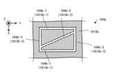
- At least one of the galvano mirrors 1341 and 1313 allows the processing light EL to scan the processing shot area PSA determined with the processing head 13 as a reference. That is, at least one of the galvanometer mirrors 1341 and 1313 allows the irradiation position PA to move within the processing shot area PSA determined with the processing head 13 as a reference.
- An example of the processing shot area PSA is shown in FIG. 4.
- the machining shot area PSA is an area (in other words, an area) where machining is performed by the machining head 13 while the positional relationship between the machining head 13 and the workpiece W is fixed (that is, without changing). ) is shown.
- the processing shot area PSA coincides with the scanning range of the processing light EL deflected by at least one of the galvanometer mirrors 1341 and 1313 with the positional relationship between the processing head 13 and the workpiece W being fixed, or the processing shot area PSA coincides with the scanning range of the processing light EL deflected by at least one of the galvano mirrors 1341 and 1313.
- the area is set to be narrower than the range.
- the processing shot area PSA irradiation position PA
- the scanning range of the processing light EL mentioned above may be the maximum range among the ranges scanned by the processing light EL.
- each of the galvano mirrors 1341 and 1313 may be considered to function as a position changing device that can change the incident position of the processing light EL into the irradiation optical system 135 by deflecting the processing light EL. .
- the incident angle typically The angle of incidence of the optical system 135 with respect to the optical axis EX may be changed.
- the irradiation optical system 135 is an optical system that can irradiate the workpiece W with the processing light EL.
- the irradiation optical system 135 includes an f ⁇ lens 1351 that can function as an objective optical system. Processing light EL emitted from the deflection optical system 134 enters the f ⁇ lens 1351 .
- the f ⁇ lens 1351 irradiates the work W with the processing light EL emitted from the deflection optical system 134. Specifically, the f ⁇ lens 1351 emits the processing light EL in a direction along the optical axis EX of the irradiation optical system 135.
- the processing light EL emitted by the f ⁇ lens 1351 enters the workpiece W by traveling along the direction along the optical axis EX.
- the optical axis EX of the irradiation optical system 135 may be the optical axis of the f ⁇ lens 1351.
- the f ⁇ lens 1351 may focus the processing light EL from the galvano mirror 1341 onto the workpiece W.
- the processing light EL emitted from the f ⁇ lens 1351 may be irradiated onto the work W without passing through another optical element (in other words, an optical member, such as a lens) having power.
- the f ⁇ lens 1351 is the optical element having the final stage power (that is, the optical element closest to the workpiece W) among the plurality of optical elements arranged on the optical path of the processing light EL, so the f ⁇ lens 1351 is the final optical element. It may also be called an element.
- the power of the optical element may be the reciprocal of the focal length of the optical element.
- the processing light EL from the galvanometer mirror 1341 may be a parallel light beam.
- the irradiation optical system 135 may include an objective optical system having a projection characteristic different from f ⁇ .
- At least one of the X scanning mirror 1341X and Y scanning mirror 1341Y that constitute the galvano mirror 1341, and the X scanning mirror 1313X and Y scanning mirror 1313Y that constitute the galvano mirror 1313 is an f ⁇ lens as an irradiation optical system. 1351 and/or its conjugate position.
- a relay optical system for making each scanning mirror optically conjugate with each other may be arranged between the scanning mirrors.
- the measurement light ML generated by the measurement light source 12 is incident on the processing head 13 via an optical transmission member 121 such as an optical fiber.
- the measurement light source 12 may be placed outside the processing head 13.
- the measurement light source 12 may be placed inside the processing head 13.
- the measurement light source 12 may include an optical comb light source.
- An optical comb light source is a light source that can generate pulsed light containing frequency components arranged at equal intervals on a frequency axis (hereinafter referred to as "optical frequency comb").
- the measurement light source 12 emits pulsed light including frequency components arranged at equal intervals on the frequency axis as the measurement light ML.
- the measurement light source 12 may include a light source different from the optical comb light source.
- the processing system SYSa includes a plurality of measurement light sources 12.
- the processing system SYSa may include a measurement light source 12#1 and a measurement light source 12#2.
- the plurality of measurement light sources 12 may each emit a plurality of measurement lights ML that are phase-synchronized and coherent with each other.
- the plurality of measurement light sources 12 may have different oscillation frequencies. Therefore, the plurality of measurement lights ML emitted by the plurality of measurement light sources 12 are different from each other in pulse frequency (for example, the number of pulsed lights per unit time, which is the reciprocal of the pulsed light emission period). It may be .
- the processing system SYSa may include a single measurement light source 12.
- the measurement light ML emitted from the measurement light source 12 enters the measurement optical system 132.
- the measurement optical system 132 is an optical system that emits the measurement light ML that has entered the measurement optical system 132 toward the synthesis optical system 133.
- the measurement light ML emitted by the measurement optical system 132 is irradiated onto the measurement object M via the synthesis optical system 133, the deflection optical system 134, and the irradiation optical system 135.
- the measurement optical system 132 includes, for example, a mirror 1320, a beam splitter 1321, a beam splitter 1322, a detector 1323, a beam splitter 1324, a mirror 1325, a detector 1326, a mirror 1327, and a galvano mirror 1328. Be prepared.
- the measurement light ML emitted from the measurement light source 12 enters the beam splitter 1321.
- measurement light ML emitted from measurement light source 12 #1 (hereinafter referred to as “measurement light ML #1”) enters beam splitter 1321.
- Measurement light ML emitted from measurement light source 12#2 (hereinafter referred to as “measurement light ML#2”) enters beam splitter 1321 via mirror 1320.
- Beam splitter 1321 emits measurement lights ML#1 and ML#2 that have entered beam splitter 1321 toward beam splitter 1322. In other words, the beam splitter 1321 emits the measurement lights ML#1 and ML#2, which are incident on the beam splitter 1321 from different directions, in the same direction (that is, the direction in which the beam splitter 1322 is arranged).
- Beam splitter 1322 reflects measurement light ML#1-1, which is a part of measurement light ML#1 incident on beam splitter 1322, toward detector 1323. Beam splitter 1322 emits measurement light ML#1-2, which is another part of measurement light ML#1 that has entered beam splitter 1322, toward beam splitter 1324. Beam splitter 1322 reflects measurement light ML#2-1, which is part of measurement light ML#2 that has entered beam splitter 1322, toward detector 1323. Beam splitter 1322 emits measurement light ML#2-2, which is another part of measurement light ML#2 that has entered beam splitter 1322, toward beam splitter 1324.
- the detector 1323 receives (that is, detects) measurement light ML#1-1 and measurement light ML#2-1.
- the detector 1323 receives interference light generated by interference between measurement light ML#1-1 and measurement light ML#2-1.
- the operation of receiving interference light generated by interference between measurement light ML#1-1 and measurement light ML#2-1 is performed by measurement light ML#1-1 and measurement light ML#2-1. may be considered to be equivalent to the operation of receiving light.
- the detection result of the detector 1323 is output to the control unit 2.
- Beam splitter 1324 emits at least a portion of measurement light ML#1-2 that has entered beam splitter 1324 toward mirror 1325.
- Beam splitter 1324 emits at least a portion of measurement light ML#2-2 that has entered beam splitter 1324 toward mirror 1327.
- Measurement light ML#1-2 emitted from beam splitter 1324 enters mirror 1325.
- Measurement light ML#1-2 incident on mirror 1325 is reflected by a reflective surface of mirror 1325 (the reflective surface may be referred to as a reference surface).
- the mirror 1325 reflects the measurement light ML#1-2 that has entered the mirror 1325 toward the beam splitter 1324. That is, the mirror 1325 emits the measurement light ML#1-2 that has entered the mirror 1325 toward the beam splitter 1324 as the measurement light ML#1-3 that is reflected light.
- measurement lights ML#1-3 may be referred to as reference lights.
- Measurement light ML#1-3 emitted from mirror 1325 enters beam splitter 1324.
- the beam splitter 1324 emits the measurement lights ML#1-3 that have entered the beam splitter 1324 toward the beam splitter 1322. Measurement light ML#1-3 emitted from beam splitter 1324 enters beam splitter 1322. Beam splitter 1322 emits measurement light ML#1-3 that has entered beam splitter 1322 toward detector 1326.
- measurement light ML#2-2 emitted from beam splitter 1324 enters mirror 1327.
- Mirror 1327 reflects measurement light ML#2-2 that has entered mirror 1327 toward galvano mirror 1328.
- the mirror 1327 emits the measurement light ML#2-2 that has entered the mirror 1327 toward the galvanometer mirror 1328.
- the galvanometer mirror 1328 deflects the measurement light ML#2-2 (that is, changes the emission angle of the measurement light ML#2-2).
- the galvanometer mirror 1328 deflects the measurement light ML#2-2 in a plane intersecting the optical axis EX of the irradiation optical system 135 (that is, in a plane along the XY plane). Change the light focusing position.
- the processing head 13 directs the measurement beam ML to the measurement object M in a state where the optical axis EX intersects the surface of the measurement object M (workpiece W in the example shown in FIG. 3). Irradiate #2-2.
- the irradiation position MA of measurement light ML#2-2 on the surface of measurement target M changes It is changed (that is, moved) in the direction along the surface of the object M. That is, the irradiation position MA of the measurement light ML#2-2 is changed along at least one of the X-axis direction and the Y-axis direction.
- the galvano mirror 1328 can change the irradiation position MA of the measurement light ML#2-2, and therefore may be referred to as a position changing optical system or a position changing device.
- the galvanometer mirror 1328 includes an X scanning mirror 1328X and a Y scanning mirror 1328Y.
- Each of the X scanning mirror 1328X and the Y scanning mirror 1328Y is a variable tilt angle mirror whose angle with respect to the optical path of the measurement light ML#2-2 incident on the galvanometer mirror 1328 is changed.
- the X scanning mirror 1328X deflects the measurement light ML#2-2 so as to change the irradiation position MA of the measurement light ML#2-2 on the measurement target M along the X-axis direction.
- the X scanning mirror 1328X may be rotatable or swingable around the Y axis.
- the galvanometer mirror 1328 changes the irradiation position MA of the measurement light ML#2-2 on the measurement object M by changing the position of the X scanning mirror 1328X in the ⁇ Y direction (or the posture around the Y axis). It may be changeable along the X-axis direction.
- the Y scanning mirror 1328Y deflects the processing light EL so as to change the irradiation position MA of the measurement light ML#2-2 on the measurement object M along the Y-axis direction.
- the Y scanning mirror 1328Y may be rotatable or swingable around the X axis.
- the galvanometer mirror 1328 changes the irradiation position MA of the measurement light ML#2-2 on the measurement target M by changing the position in the ⁇ X direction (or the posture around the X axis) of the Y scanning mirror 1328Y. It may be changeable along the Y-axis direction.
- Measurement light ML#2-2 emitted from the measurement optical system 132 enters the synthesis optical system 133.
- the beam splitter 1331 of the combining optical system 133 emits the measurement light ML#2-2 that has entered the beam splitter 1331 toward the deflection optical system 134.
- the measurement light ML#2-2 that has entered the combining optical system 133 is reflected by the polarization separation surface and is emitted toward the deflection optical system 134. Therefore, in the example shown in FIG.
- the measurement light ML#2-2 is sent to the beam splitter in a state where it has a polarization direction that can be reflected by the polarization separation surface (for example, a polarization direction that becomes s-polarized light with respect to the polarization separation surface).
- the light is incident on the polarization separation surface of 1331.
- the processing light EL enters the beam splitter 1331 in addition to the measurement light ML#2-2. That is, both the measurement light ML#2-2 and the processing light EL pass through the beam splitter 1331.
- the beam splitter 1331 directs the processing light EL and the measurement light ML#2-2, which have entered the beam splitter 1331 from different directions, in the same direction (that is, toward the same deflection optical system 134). Therefore, the beam splitter 1331 substantially functions as a combining optical member that combines the processing light EL and the measurement light ML#2-2.
- the combining optical system 133 may include a dichroic mirror instead of the beam splitter 1331 as a combining optical member. Even in this case, the combining optical system 133 uses a dichroic mirror to combine the processing light EL and the measurement light ML#2-2 (that is, the optical path of the processing light EL and the measurement light ML#2-2). can be combined with the optical path).
- Measurement light ML#2-2 emitted from the combining optical system 133 enters the deflection optical system 134.
- the deflection optical system 134 emits the measurement light ML#2-2 that has entered the deflection optical system 134 toward the irradiation optical system 135.
- the measurement light ML#2-2 that entered the deflection optical system 134 enters the galvanometer mirror 1341.
- the galvanometer mirror 1341 deflects the measurement light ML#2-2 in the same way as when deflecting the processing light EL. Therefore, the galvanometer mirror 1341 can change the irradiation position MA of the measurement light ML#2-2 on the surface of the measurement object M in the direction along the surface of the measurement object M. In other words, the galvanometer mirror 1341 changes the irradiation position MA of the measurement light ML#2-2 on the measurement target M by changing the position of the X scanning mirror 1341X in the ⁇ Y direction (or the posture around the Y axis). It may be changeable along the X-axis direction.
- the galvanometer mirror 1341 changes the irradiation position MA of the measurement light ML#2-2 on the measurement target M on the Y axis by changing the position in the ⁇ X direction (or the posture around the X axis) of the Y scanning mirror 1341Y. It may be changeable along the direction. In this way, the galvano mirror 1341 can change the irradiation position MA of the measurement light ML#2-2, and therefore may be referred to as a position changing optical system or a position changing device.
- the processing light EL is incident on the galvanometer mirror 1341 in addition to the measurement light ML#2-2. That is, the processing light EL and measurement light ML#2-2 combined by the beam splitter 1331 are incident on the galvanometer mirror 1341. Therefore, both the measurement light ML#2-2 and the processing light EL pass through the same galvanometer mirror 1341. Therefore, the galvanometer mirror 1341 can synchronize and change the irradiation position PA of the processing light EL and the irradiation position MA of the measurement light ML#2-2. In other words, the galvanometer mirror 1341 can change the irradiation position PA of the processing light EL and the irradiation position MA of the measurement light ML#2-2 in conjunction with each other.
- the processing system SYSa can use the galvano mirror 1328 to move the irradiation position MA of the measurement light ML#2-2 independently with respect to the irradiation position PA of the processing light EL. That is, the processing system SYSa can use the galvanometer mirror 1328 to change the relative positional relationship between the irradiation position PA of the processing light EL and the irradiation position MA of the measurement light ML#2-2.
- the processing system SYSa uses the galvanometer mirror 1328 to determine the relative positional relationship between the irradiation position PA of the processing light EL and the irradiation position MA of the measurement light ML#2-2. It can be changed along the direction intersecting the irradiation direction (in the example shown in FIG. 3, at least one of the X-axis direction and the Y-axis direction).
- the processing system SYSa can independently move the irradiation position PA of the processing light EL with respect to the irradiation position MA of the measurement light ML#2-2 using the galvanometer mirror 1313. That is, the processing system SYSa can use the galvanometer mirror 1313 to change the relative positional relationship between the irradiation position PA of the processing light EL and the irradiation position MA of the measurement light ML#2-2.
- the processing system SYSa uses a galvanometer mirror 1328 to adjust the relative positional relationship between the irradiation position PA of the processing light EL and the irradiation position MA of the measurement light ML#2-2, such that the direction intersects the irradiation direction of the processing light EL. (in the example shown in FIG. 3, at least one of the X-axis direction and the Y-axis direction).
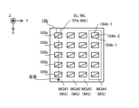
- At least one of the galvanometer mirrors 1341 and 1328 allows the measurement light ML#2-2 to scan the measurement shot area MSA determined with the processing head 13 as a reference. That is, at least one of the galvanometer mirrors 1341 and 1328 allows the irradiation position MA to be moved within the measurement shot area MSA determined with the processing head 13 as a reference.
- An example of the measurement shot area MSA is shown in FIG. As shown in FIG. 5, the measurement shot area MSA is an area where the processing head 13 performs measurement while the positional relationship between the processing head 13 and the measurement target M is fixed (that is, without changing). , range).
- the measurement shot area MSA coincides with the scanning range of the measurement light ML deflected by at least one of the galvano mirrors 1341 and 1328 while the positional relationship between the processing head 13 and the measurement target M is fixed.
- the area is set to be narrower than the scanning range.
- the measurement shot area MSA irradiation position MA
- the scanning range of the measurement light ML mentioned above may be the maximum range among the ranges scanned by the measurement light ML.
- measurement light ML#2-2 emitted from the deflection optical system 134 enters the irradiation optical system 135.
- the irradiation optical system 135 of the measurement light ML#2-2 The incident position changes. Therefore, each of the galvano mirrors 1341 and 1328 functions as a position changing device that can change the incident position of the measurement light ML#2-2 onto the irradiation optical system 135 by deflecting the measurement light ML#2-2. It may be assumed that
- the irradiation optical system 135 is an optical system that can irradiate the measurement target M (in the example shown in FIG. 3, the workpiece W) with the measurement light ML#2-2.
- the f ⁇ lens 1351 irradiates the measurement object M with the measurement light ML#2-2 emitted from the deflection optical system 134.
- the f ⁇ lens 1351 emits the measurement light ML#2-2 in the direction along the optical axis EX of the irradiation optical system 135.
- the measurement light ML#2-2 emitted by the f ⁇ lens 1351 travels in the direction along the optical axis EX and enters the measurement target M.
- the f ⁇ lens 1351 may focus the measurement light ML#2-2 emitted from the deflection optical system 134 onto the measurement target M.
- the measurement light ML#2-2 emitted from the f ⁇ lens 1351 reaches the measurement target M without passing through another optical element having power (in other words, an optical member such as a lens). It may be irradiated.
- the f ⁇ lens 1351 is the optical element having the power of the final stage (that is, the optical element closest to the workpiece W) among the plurality of optical elements arranged on the optical path of the measurement light ML#2-2. Therefore, it may also be referred to as the final optical element.
- the measurement light ML#2-2 that is emitted from the deflection optical system 134 and enters the f ⁇ lens 1351 may be a parallel light beam.
- the measurement object M When the measurement object M is irradiated with the measurement light ML#2-2, light resulting from the irradiation of the measurement light ML#2-2 is generated from the measurement object M. That is, when the measurement object M is irradiated with the measurement light ML#2-2, light resulting from the irradiation of the measurement light ML#2-2 is emitted from the measurement object M.
- the light caused by the irradiation of the measurement light ML#2-2 (in other words, the light emitted from the measurement object M due to the irradiation of the measurement light ML#2-2) is reflected by the measurement object M.
- Measurement light ML#2-2 (that is, reflected light), measurement light ML#2-2 scattered by measurement object M (that is, scattered light), measurement light ML#2-2 that was diffracted by measurement object M 2 (that is, diffracted light), and measurement light ML#2-2 that has passed through the measurement object M (that is, transmitted light).
- the optical path of the measurement light ML#2-2 that is emitted from the irradiation optical system 135 and enters the measurement object M, and the optical path of the return light RL that is emitted from the measurement object M and enters the irradiation optical system 135. may be the same.
- the return light RL that has entered the irradiation optical system 135 enters the deflection optical system 134 via the f ⁇ lens 1351.
- the return light RL that has entered the deflection optical system 134 enters the combining optical system 133 via the galvano mirror 1341.
- the beam splitter 1331 of the combining optical system 133 emits the return light RL that has entered the beam splitter 1331 toward the measurement optical system 132.
- the return light RL that has entered the beam splitter 1331 is reflected on the polarization separation surface and is emitted toward the measurement optical system 132. Therefore, in the example shown in FIG. 3, the returned light RL enters the polarization separation surface of the beam splitter 1331 in a state where it has a polarization direction that can be reflected by the polarization separation surface.
- the return light RL emitted from the beam splitter 1331 enters the galvanometer mirror 1328 of the measurement optical system 132.
- the galvano mirror 1328 emits the return light RL that has entered the galvano mirror 1328 toward the mirror 1327 .
- Mirror 1327 reflects the return light RL that has entered mirror 1327 toward beam splitter 1324 .
- Beam splitter 1324 emits at least a portion of the return light RL that has entered beam splitter 1324 toward beam splitter 1322 .
- Beam splitter 1322 emits at least a portion of the return light RL that has entered beam splitter 1322 toward detector 1326.
- the measurement light ML#1-3 enters the detector 1326 in addition to the return light RL. That is, the return light RL directed toward the detector 1326 via the measurement target M and the measurement light ML#1-3 directed toward the detector 1326 without passing through the measurement target M enter the detector 1326.
- the detector 1326 receives (that is, detects) the measurement light ML#1-3 and the return light RL.
- the detector 1326 receives interference light generated by interference between measurement light ML#1-3 and return light RL.
- the operation of receiving interference light generated by interference between measurement light ML#1-3 and return light RL is equivalent to the operation of receiving measurement light ML#1-3 and return light RL. It may be considered as
- the detection result of the detector 1326 is output to the control unit 2.
- the control unit 2 acquires the detection results of the detector 1323 and the detection results of the detector 1326.
- the control unit 2 generates measurement data of the measurement target M (for example, measurement data regarding at least one of the position and shape of the measurement target M) based on the detection results of the detector 1323 and the detection result of the detector 1326. You can.
- the pulse frequency of measurement light ML#1 and the pulse frequency of measurement light ML#2 are different, the pulse frequency of measurement light ML#1-1 and the pulse frequency of measurement light ML#2-1 are different. different. Therefore, the interference light between measurement light ML#1-1 and measurement light ML#2-1 is such that the pulsed light forming measurement light ML#1-1 and the pulsed light forming measurement light ML#2-1 are different from each other. At the same time, pulsed light appears in synchronization with the timing of incidence on the detector 1323, resulting in interference light. Similarly, the pulse frequency of the measurement lights ML#1-3 and the pulse frequency of the return light RL are different.
- the interference light between the measurement light ML#1-3 and the return light RL is generated at the timing when the pulsed light forming the measurement light ML#1-3 and the pulsed light forming the return light RL simultaneously enter the detector 1326.
- the result is interference light in which pulsed light appears in synchronization with .
- the position (position on the time axis) of the pulsed interference light detected by the detector 1326 varies depending on the positional relationship between the processing head 13 and the measurement target M. This is because the interference light detected by the detector 1326 includes the return light RL that goes to the detector 1326 via the measurement object M, and the measurement light ML#1-3 that goes to the detector 1326 without going through the measurement object M.
- the position (position on the time axis) of the pulsed interference light detected by the detector 1323 is determined by the positional relationship between the processing head 13 and the measurement target M (that is, the position between the processing head 13 and the measurement object M). It does not change depending on the positional relationship with the object M). Therefore, the time difference between the pulsed interference light detected by the detector 1326 and the pulsed interference light detected by the detector 1323 indirectly indicates the positional relationship between the processing head 13 and the measurement target M. I can say that.
- the time difference between the pulsed interference light detected by the detector 1326 and the pulsed interference light detected by the detector 1323 is determined by the time difference in the direction along the optical path of the measurement light ML (that is, the direction along the optical path of the measurement light ML). It can be said that the distance between the processing head 13 and the measurement object M in the direction (along the direction) is indirectly indicated. Therefore, the control unit 2 controls the direction along the optical path of the measurement light ML (for example, based on the time difference between the pulsed interference light detected by the detector 1326 and the pulsed interference light detected by the detector 1323 The distance between the processing head 13 and the object to be measured M in the Z-axis direction can be calculated.
- the control unit 2 can calculate the position of the measurement target object M in the direction (for example, the Z-axis direction) along the optical path of the measurement light ML. More specifically, the control unit 2 can calculate the distance between the processing head 13 and the irradiated portion of the measurement target M that is irradiated with the measurement light ML#2-2. The control unit 2 can calculate the position of the irradiated portion in the direction along the optical path of the measurement light ML (for example, the Z-axis direction). Furthermore, since the irradiation position of the measurement light ML#2-2 on the measurement target M is determined by the driving states of the galvano mirrors 1341 and 1328, the control unit 2 controls the driving states of the galvano mirrors 1341 and 1328.
- the control unit 2 can generate measurement data indicating the position of the irradiated portion in the measurement coordinate system based on the processing head 13 (for example, the position in a three-dimensional coordinate space).
- the processing head 13 may irradiate measurement light ML#2-2 onto multiple parts of the measurement target M.
- at least one of the galvanometer mirrors 1341 and 1328 is configured to irradiate the measurement light ML#2 on the measurement target M so that the processing head 13 irradiates the measurement light ML#2-2 onto multiple parts of the measurement target M.
- -2 irradiation position may be changed.
- at least one of the processing head 13 and the stage 15 may be moved so that the processing head 13 irradiates the measurement light ML#2-2 onto a plurality of parts of the measurement target M.
- the control unit 2 can generate measurement data indicating the positions of the plurality of parts of the measurement object M.
- the control unit 2 can generate measurement data indicating the shape of the measurement target M based on measurement data indicating the positions of the plurality of parts. For example, the control unit 2 calculates, as the shape of the measurement object M, a three-dimensional shape composed of a virtual plane (or curved surface) connecting a plurality of parts whose positions have been specified. Measurement data indicating the shape of M can be generated.
- FIG. 1 (1-3) Structure of processing head 13 with replaceable irradiation optical system 135
- the processing light EL is irradiated onto the workpiece W
- the measurement light ML is irradiated onto the measurement target M.
- the irradiation optical system 135 is replaceable.
- the configuration of the processing head 13 in which the irradiation optical system 135 is replaceable will be further described below with reference to FIG.
- the processing optical system 131, the measurement optical system 132, the combining optical system 133, and the deflection optical system 134 may be housed in a head housing 136 of the processing head 13.
- the irradiation optical system 135 may be housed in a head housing 137 of the processing head 13 that is different from the head housing 136. Note that at least one of the head housings 136 and 137 may be referred to as a lens barrel.
- the processing light EL is transmitted to the irradiation optical system 135 housed in the head housing 137 via the processing optical system 131, measurement optical system 132, synthesis optical system 133, and deflection optical system 134 housed in the head housing 136. and measurement light ML are incident. That is, the optical system including the processing optical system 131, the measurement optical system 132, the combining optical system 133, and the deflection optical system 134 housed in the head housing 136 emits the processing light EL and the measurement light ML to the irradiation optical system 135. .
- an optical system including a processing optical system 131, a measurement optical system 132, a combining optical system 133, and a deflection optical system 134 will be described, and a processing light EL and a measurement light ML will be used in an irradiation optical system 135. It is called an exit optical system 130 for emitting light.
- the head housing 137 can be attached to the head housing 136.
- the head housing 137 attached to the head housing 136 is removable from the head housing 136. That is, the head housing 137 is removable from the head housing 136.
- the irradiation optical system 135 housed in the head housing 137 can be attached to the emission optical system 130 housed in the head housing 136.
- Illumination optics 135 attached to exit optics 130 may be considered removable from exit optics 130 .
- the irradiation optical system 135 may be considered to be detachable from the emission optical system 130.
- the head housing 137 may be removably attached to the head housing 136 via the mounting adapter 138. That is, the irradiation optical system 135 may be detachable from the injection optical system 130 via the mounting adapter 138. However, the head housing 137 may be detachable from the head housing 136 without using the attachment adapter 138. That is, the irradiation optical system 135 may be detachable from the injection optical system 130 without using the attachment adapter 138.
- FIG. 6 An example of the mounting adapter 138 is shown in FIG. As shown in FIG. 6, the mounting adapter 138 may be attached to the head housing 136.
- the mounting adapter 138 has a top surface (specifically, the surface facing the +Z side) of the mounting adapter 138 that is connected to a bottom surface of the head housing 136 (specifically, the surface facing the -Z side).
- the head casing 136 may be attached to the head housing 136 so as to face the head casing 136 .
- the lower surface of the mounting adapter 138 (specifically, the surface facing the -Z side) may be used as the mounting surface 1380 to which the head housing 137 is attached. That is, the head housing 137 may be attached to the attachment adapter 138 such that the attachment surface 1370, which is the upper surface of the head housing 137, faces the attachment surface 1380 of the attachment adapter 138. As a result, head housing 137 is attached to head housing 136 via attachment adapter 138.
- At least one attachment pin 1381 may be formed on the attachment surface 1380 of the attachment adapter 138.
- At least one attachment pin 1382 may be formed on the side surface of each attachment pin 1381. As shown in the enlarged view of the mounting pin 1381 on the right side of FIG. 1381) and a state in which each mounting pin 1382 is not housed inside the mounting pin 1381 (as a result, each mounting pin 1382 protrudes from the side of the mounting pin 1381). It may be switchable.
- each mounting pin 1382 is such that each mounting pin 1382 is accommodated inside the mounting pin 1381 using the force that moves the mounting pin 1382, and the state where each mounting pin 1382 is accommodated inside the mounting pin 1381. It is possible to switch between the state where it is not
- the force that moves the attachment pin 1382 may be a force applied to the attachment pin 1382 from the head housing 137.
- the attachment pin 1382 may come into contact with the surface of the head housing 137 (for example, the surface forming the attachment hole 1371 described later). In this case, a force is applied to the mounting pin 1382 that pushes out the mounting pin 1382 from the surface of the head housing 137.
- the attachment pin 1382 may be moved by a force that pushes out the attachment pin 1382 from the surface of the head housing 137.
- the mounting pin 1382 may be accommodated inside the mounting pin 1381 by a force that pushes out the mounting pin 1382 from the surface of the head housing 137.
- the curvature of at least a portion of the surface of the mounting pin 1382 may be set to an appropriate curvature so that force is appropriately applied to the mounting pin 1382 from the surface of the head housing 137.
- At least a portion of the surface of the attachment pin 1382 may be a curved surface.
- the force that moves the attachment pin 1382 may be, for example, a force caused by gas (for example, air).
- the force that moves the attachment pin 1382 may be, for example, a force due to gas (eg, air) pressure.
- a pneumatic device supplying gas may move the mounting pin 1382.
- a purge gas may be used as the gas for moving the attachment pin 1382, or a gas different from the purge gas may be used.
- the two mounting pins 1381 are arranged on a straight line intersecting the optical axis EX of the irradiation optical system 135.
- the number of attachment pins 1381 is not limited to two.
- a single mounting pin 1381 may be formed.
- Three or more attachment pins 1381 may be formed.
- a mounting hole 1371 may be formed in the mounting surface 1370 of the head housing 137 into which a mounting pin 1381 of the mounting adapter 138 can be inserted.
- the number of attachment holes 1371 formed in the head housing 137 may be the same as the number of attachment pins 1381 formed in the attachment adapter 138.
- the mounting hole 1371 may be connected to a mounting hole 1372 into which a mounting pin 1382 of the mounting adapter 138 can be inserted.
- the number of attachment holes 1372 connected to each attachment hole 1371 may be the same as the number of attachment pins 1382 formed in each attachment pin 1381.
- each attachment pin 1382 in order to attach the head housing 137 to the attachment adapter 138, the state of each attachment pin 1382 is changed to a state in which each attachment pin 1382 is housed inside the attachment pin 1381, as shown in FIG. 7(a). may be switched to Thereafter, the head housing 137 may be aligned with the mounting adapter 138 so that each mounting pin 1381 is inserted into each mounting hole 1371, as shown in FIG. 7(b). Thereafter, as shown in FIG. 7C, the state of each mounting pin 1382 may be switched to a state in which each mounting pin 1382 is not housed inside the mounting pin 1381. As a result, as shown in FIG.
- the mounting pin 1382 is inserted into the mounting hole 1372, and the head housing 137 is fixed to the mounting adapter 138. That is, the head housing 137 is attached to the head housing 136. In other words, the irradiation optical system 135 is attached to the exit optical system 130.
- each mounting pin 1381 may be removed from each mounting hole 1371, as shown in FIG. 7(a).
- the head housing 137 is removed from the mounting adapter 138, as shown in FIG. 7(a). That is, the head housing 137 is removed from the head housing 136.
- the irradiation optical system 135 is removed from the exit optical system 130.
- a groove may be formed in at least one of the mounting surface 1380 of the mounting adapter 138 and the mounting surface 1370 of the head housing 137.
- the groove may be evacuated.
- the control unit 2 may determine whether the head housing 137 is properly attached to the attachment adapter 138 based on the air pressure of the evacuated groove.
- the force that moves the attachment pin 1382 may include a force caused by a spring (or any elastic body) in addition to the force caused by the gas described above.
- the state of the mounting pin 1382 may be set such that the mounting pin 1382 protrudes from the side surface of the mounting pin 1381 due to a force applied to the mounting pin 1382 from a spring. In this state, the state of the mounting pin 1382 may be switched to a state in which the mounting pin 1382 is housed inside the mounting pin 1381 by the force caused by the gas.
- the mounting pin 1382 protrudes from the side surface of the mounting pin 1381, while when the pneumatic device is in the ON state, the mounting pin 1382 protrudes from the side surface of the mounting pin 1381.
- 1382 may be housed inside the mounting pin 1381. In this case, even if the pneumatic device breaks down due to an unexpected situation (that is, even if the pneumatic device is turned off), the head housing 137 can be attached to the mounting adapter 138. It will never come off. Therefore, damage to the irradiation optical system 135 due to falling can be prevented.
- the mounting pin 1381 and the mounting hole 1371 can function as a fall prevention mechanism that prevents the head housing 137 from falling from the mounting adapter 138.
- the mounting pin 1381 and the mounting hole 1371 can function as a drop-off prevention mechanism that prevents the head housing 137 from falling off the mounting adapter 138.
- the processing head 13 may include other fall prevention mechanisms (fall prevention mechanisms) in addition to the fall prevention mechanisms (fall prevention mechanisms) including the mounting pins 1381 and the attachment holes 1371.
- the mounting adapter 138 is attached to the head housing 136.
- the attachment adapter 138 may be attached to the head housing 137.
- a plurality of head housings 137 are selectively attached to the head housing 136, as described later.
- a mounting adapter 138 may be attached to each of the plurality of head housings 137.
- FIG. 8 is a cross-sectional view conceptually showing an example of the configuration of the head exchanging device 17. As shown in FIG.
- the head exchange device 17 includes a storage device 171, a transport device 172, and a housing 173.
- the housing device 171 can house the irradiation optical system 135 that can be attached to the processing head 13.
- the housing device 171 may be capable of housing a plurality of irradiation optical systems 135, each of which can be attached to the processing head 13.
- the housing device 171 includes N (N is a variable representing an integer of 2 or more) irradiation optical systems 135 (specifically, irradiation optical systems 135#1 to 135). #N) is accommodated.
- the housing device 171 may be capable of housing the irradiation optical system 135 housed in the head housing 137.
- the housing device 171 may be capable of housing the head housing 137 in which the irradiation optical system 135 is housed.
- the housing device 171 may house a plurality of irradiation optical systems 135 having mutually different optical characteristics. Examples of a plurality of irradiation optical systems 135 having different optical characteristics are shown in FIGS. 9(a) to 9(g). FIGS. 9(a) to 9(g) each show seven irradiation optical systems 135 having different optical characteristics.
- the housing device 171 may house a plurality of irradiation optical systems 135 having different numerical apertures NA (Numerial Apertures).
- NA numerical aperture
- NA numerical aperture
- the numerical aperture NA of the irradiation optical system 135 increases, processing accuracy and measurement accuracy become higher, but the possibility that the irradiation optical system 135 collides with the workpiece W (or the object to be measured M) increases.
- the storage device 171 has the effect of improving processing accuracy and measurement accuracy (hereinafter referred to as accuracy improvement effect), and the effect of preventing collision between the irradiation optical system 135 and the workpiece W (or measurement target M). (hereinafter referred to as collision prevention effect), a plurality of irradiation optical systems 135 having different numerical apertures NA may be accommodated.
- the working distance may be the distance along the optical axis EX from the final optical element of the irradiation optical system 135 to the focusing position of the processing light EL.
- the working distance may be the distance along the optical axis EX from the optical element disposed closest to the exit side among the one or more optical elements constituting the irradiation optical system 135 to the condensing position of the processing light EL. .
- the working distance may be the distance along the direction parallel to the optical axis EX from the part of the head housing 137 that accommodates the irradiation optical system 135 located closest to the work W to the condensing position of the processing light EL. good.
- the focusing position of the processing light EL may be the rear focal position of the irradiation optical system 135.
- the housing device 171 may house an irradiation optical system 135-1 in which the numerical aperture NA is set to the first numerical aperture NA1 in order to achieve both an accuracy improvement effect and a collision prevention effect.
- the housing device 171 in addition to or in place of the irradiation optical system 135-1, the housing device 171 has a numerical aperture NA larger than the first numerical aperture NA1 in order to give priority to the accuracy improvement effect over the collision prevention effect.
- An irradiation optical system 135-2 set to a second numerical aperture NA2 may be accommodated.
- the housing device 171 may have a first numerical aperture NA in order to prioritize the collision prevention effect over the accuracy improvement effect.
- An irradiation optical system 135-3 may be accommodated, which is set to a third numerical aperture NA3 smaller than the numerical aperture NA1.
- the processing system SYSa when the irradiation optical system 135-1 is attached to the processing head 13, the processing system SYSa reduces the possibility of collision between the irradiation optical system 135 and the workpiece W (or the measurement object M). It is possible to process the workpiece W with the first processing accuracy and measure the measurement object M with the first measurement accuracy. Further, when the irradiation optical system 135-2 is attached to the processing head 13, the processing system SYSa processes the workpiece W with a second processing accuracy higher than the first processing accuracy, and The measurement target M can be measured with a second measurement accuracy higher than the measurement accuracy of .
- the processing system SYSa when the irradiation optical system 135-3 is attached to the processing head 13, compared to the case where the irradiation optical system 135-1 is attached to the processing head 13, the processing system SYSa is Collision between the workpiece 135 and the workpiece W (or the measurement object M) can be further prevented. Furthermore, since the working distance becomes longer, the processing system SYSa appropriately processes the workpiece W so as to form a deep hole in the workpiece W, as shown in FIG. It is possible to properly measure the inside of a deep hole formed in a hole.
- the housing device 171 may house an irradiation optical system 135-4 specialized for processing the workpiece W using the processing light EL.
- the housing device 171 may house an irradiation optical system 135-4 that prioritizes improving processing accuracy over improving measurement accuracy.
- the housing device 171 may house the irradiation optical system 135-4 designed only to improve processing accuracy without giving any consideration to improving measurement accuracy. In this case, when the irradiation optical system 135-4 is attached to the processing head 13, the processing system SYSa can process the workpiece W more appropriately.
- the housing device 171 may house an irradiation optical system 135-5 specialized for measuring the measurement target M using the measurement light ML.
- the housing device 171 may house an irradiation optical system 135-5 that prioritizes improving measurement accuracy over improving processing accuracy.
- the accommodating device 171 may house the irradiation optical system 135-5 designed only to improve measurement accuracy without giving any consideration to improving processing accuracy. In this case, if the irradiation optical system 135-5 is attached to the processing head 13, the processing system SYSa can measure the measurement object M more appropriately.
- the accommodation device 171 includes an irradiation optical system whose size (so-called width) in a direction intersecting the irradiation direction of the processing light EL and the measurement light ML is limited to a certain size or less.
- 135-6 may be accommodated. Since the irradiation optical system 135-6 is housed in the head housing 137, the accommodating device 171 has a size (so-called width) in a direction intersecting the irradiation direction of the processing light EL and the measurement light ML that is below a certain size. An irradiation optical system 135-6 may be housed in a restricted head housing 137.
- the processing system SYSa can insert the Irradiation optics 135-6 can be advanced. Therefore, the processing system SYSa can appropriately process the workpiece W so as to form a deep hole in the workpiece W, and can appropriately measure the inside of the deep hole formed in the measurement target M.
- the processing light EL and the measurement light ML are provided in the accommodation device 171 in a direction intersecting the optical axis EX of the irradiation optical system 135 (for example, the optical axis of the f ⁇ lens 1351).
- An irradiation optical system 135-7 capable of emitting at least one of the above may be housed.
- the irradiation optical system 135-7 changes the traveling direction of at least one of the processing light EL and measurement light ML emitted from the f ⁇ lens 1351.
- a mirror 1352 that can reflect at least one of the MLs may be provided.
- the mirror 1352 may be rotatable around the optical axis EX of the irradiation optical system 135 (for example, the optical axis of the f ⁇ lens 1351).
- the processing system SYSa emits processing light onto the surface of the workpiece W or measurement target M along the optical axis EX of the irradiation optical system 135.
- EL or measurement light ML can be irradiated.
- the transport device 172 can transport the irradiation optical system 135 between the head exchange device 17 and the processing head 13. Specifically, the transport device 172 may take out the irradiation optical system 135 housed in the housing device 171 from the housing device 171 . Thereafter, the transport device 172 may transport the irradiation optical system 135 taken out from the storage device 171 from the storage device 171 to the processing head 13. Thereafter, the transport device 172 may attach the irradiation optical system 135 transported to the processing head 13 to the processing head 13. Furthermore, the transport device 172 may remove the irradiation optical system 135 attached to the processing head 13 from the processing head 13.
- the transport device 172 may transport the irradiation optical system 135 removed from the processing head 13 from the processing head 13 to the storage device 171. Thereafter, the transport device 172 may store the irradiation optical system 135 transported to the storage device 171 in the storage device 171.
- the control unit 2 controls which one of the irradiation optical systems 135 to be attached to the processing head 13. may be selected as the irradiation optical system 135.
- the control unit 2 selects any one of the plurality of irradiation optical systems 135 as the one irradiation optical system 135 to be attached to the processing head 13 based on instructions from the user of the processing system SYSa. You may choose.
- the control unit 2 selects any one of the plurality of irradiation optical systems 135 as the one irradiation optical system 135 to be attached to the processing head 13 based on the processing mode performed by the processing system SYSa. You may choose.
- control unit 2 selects any one of the plurality of irradiation optical systems 135 as the one irradiation optical system 135 to be attached to the processing head 13 based on the measurement mode performed by the processing system SYSa. You may choose. Thereafter, the transport device 172 may transport the one irradiation optical system 135 selected by the control unit 2 from the storage device 171 to the processing head 13.
- the transport device 172 may include a transport arm 1721 that can grasp or temporarily hold the irradiation optical system 135 in order to transport the irradiation optical system 135. In this case, the transport device 172 may transport the irradiation optical system 135 between the head exchange device 17 and the processing head 13 using the transport arm 1721.
- a magazine-type auto tool changer used in machine tools may be used as the head exchange device 17. good.
- the storage device 171 may be referred to as a magazine.
- a magazine of an auto tool changer may be used as the storage device 171.
- the cutting tools that are normally housed in the magazine may not be housed in the magazine that functions as the housing device 171 for housing the plurality of irradiation optical systems 135.
- a turret-type auto tool changer used in machine tools may be used as the head changing device 17.
- the storage device 171 may function as a tool pot having a drum shape.
- a tool pot of an auto tool changer may be used as the storage device 171.
- the cutting tool that is normally housed in the tool pot may not be housed in the tool pot that functions as the housing device 171 for housing the plurality of irradiation optical systems 135.
- the transport device 172 directly rotates the tool pot used as the storage device 171 so that the desired irradiation optical system 135 is located at the position closest to the transport device 172, and The irradiation optical system 135 located at the irradiation optical system 135 may be held or temporarily held.
- the tool pot used as the storage device 171 may be rotated so that the desired irradiation optical system 135 is located at the desired position without using the force of the transport device 172.
- the tool pot used as the storage device 171 may be rotated so that the desired irradiation optical system 135 to be attached to the processing head 13 is located closest to the +Y side.
- the desired irradiation optical system 135 moves so as to protrude from the transport port 1731 toward the +Y side, and the processing head 13 is moved so that the irradiation optical system 135 that has protruded from the transport port 1731 can be attached to the processing head 13.
- the irradiation optical system 135 that protrudes from the transport port 1731 may be approached.
- the machining system SYSa may be manufactured using the machine tool.
- the machining system SYSa may be manufactured using a machine tool by attaching the machining head 13 to the main shaft of the machine tool.
- a device inside the housing of a machine tool that has already been designed, developed, or mass-produced may be used as a component of the processing system SYSa.
- a stage of a machine tool may be used as the stage 15 of the processing system SYSa.
- a guide mechanism of a machine tool may be used as at least one of the head drive system 141 and the stage drive system 161 of the processing system SYSa.
- the device inside the housing of the machine tool may be at least partially improved, and the partially improved device may be used as a component of the machining system SYSa.
- the cost of the processing system SYSa can be reduced compared to the case where the components of the processing system SYSa are newly designed from scratch.
- the machining system SYS may use devices inside the housing of a machine tool that have already been designed, developed, or mass-produced (for example, an auto tool changer, a stage, and a guide mechanism for the head) as components of the machining system SYS.
- the housing 173 accommodates at least a portion of the storage device 171 and the transport device 172. Specifically, at least a portion of the storage device 171 and the transport device 172 are stored in a storage space 1730 inside the housing 173.
- a transport port 1731 may be formed in the casing 173.
- the transport device 172 may transport the irradiation optical system 135 between the head exchange device 17 and the processing head 13 via the transport port 1731.
- a gas supply port 1732 may be formed in the housing 173.
- a purge gas that is, gas
- nitrogen gas may be supplied to the accommodation space 1730 inside the housing 173 through a gas supply port 1732. That is, the processing system SYS may supply purge gas to the accommodation space 1730 inside the housing 173 via the gas supply port 1732 using a gas supply device (not shown).
- the atmospheric pressure of the housing space 1730 is supplied to the housing space 1730 through the gas supply port 1732 to the space outside the housing 173 (specifically, the internal space SP inside the housing 3 housing the processing unit 1).
- the purge gas may be supplied so that the pressure is higher than that of the air pressure. That is, purge gas is supplied to the accommodation space 1730 through the gas supply port 1732 so that the air pressure in the accommodation space 1730 is higher than the air pressure in the internal space SP in which the workpiece W is placed on the stage 15. Good too.
- purge gas may be supplied to the accommodation space 1730 via the gas supply port 1732 so that the air pressure in the accommodation space 1730 is higher than the air pressure in the internal space SP in which the workpiece W is processed.
- the head exchange device 17 can prevent unnecessary substances from adhering to the irradiation optical system 135 housed in the housing space 1730.
- unnecessary substances is fume generated during processing of the workpiece W.
- the purge gas may be supplied toward the irradiation optical system 135 housed in the accommodation space 1730 via the gas supply port 1732.
- the purge gas may be supplied through the gas supply port 1732 toward at least one of the plurality of irradiation optical systems 135 accommodated in the accommodation space 1730.
- the purge gas supplied toward the irradiation optical system 135 will cause the substances to adhere to the irradiation optical system 135. unnecessary substances are removed. Therefore, the head exchange device 17 can prevent unnecessary substances from adhering to the irradiation optical system 135 housed in the housing space 1730.
- purge gas may be supplied to the mounting surface 1380 of the mounting adapter 138 during at least part of the period when the head housing 137 is removed from the mounting adapter 138 (head housing 136). In this case, it is possible to prevent unnecessary substances from adhering to the mounting surface 1380.
- the period during which the purge gas is supplied to the mounting surface 1380 of the mounting adapter 138 may be the entire period during which the head housing 137 is removed from the mounting adapter 138 (head housing 136).
- the irradiation optical system 135 attached to the processing head 13 can be replaced. Therefore, compared to the case where the irradiation optical system 135 attached to the processing head 13 cannot be replaced, the processing system SYSa uses one irradiation optical system 135 that matches the processing purpose to more appropriately target the workpiece W. It can be processed into Furthermore, compared to the case where the irradiation optical system 135 attached to the processing head 13 cannot be replaced, the processing system SYSa uses one irradiation optical system 135 that matches the measurement purpose to more easily measure the measurement target M. Can be measured appropriately.
- processing system SYS in the second embodiment will be explained.
- the processing system SYS in the second embodiment will be referred to as a "processing system SYSb.”
- FIG. 10 is a block diagram showing an example of the configuration of the processing system SYSb in the second embodiment.
- the same reference numerals are given to the same components as already explained components, and detailed explanation thereof will be omitted.
- the processing system SYSb in the second embodiment differs from the processing system SYSa in the first embodiment in that it includes a processing unit 1b instead of the processing unit 1 described above. It's different.
- Other characteristics of the processing system SYSb may be the same as other characteristics of the processing system SYSa.
- the processing unit 1b differs from the processing unit 1 in that it further includes an optical measurement device 18b, a measurement drive system 191b, and a position measurement device 192b. Other features of the processing unit 1b may be the same as other features of the processing unit 1.
- the optical measurement device 18b is a member used for calibration operation.
- the calibration operation is an operation for calibrating (in other words, controlling or adjusting) at least one of the irradiation position PA of the processing light EL and the irradiation position MA of the measurement light ML.
- the calibration operation is performed under the control of the control unit 2. That is, the processing system SYSb performs a calibration operation under the control of the control unit 2.
- the details of the calibration operation and the optical measurement device 18b will be described in detail later, but the outline thereof will be briefly described below.
- the processing head 13 irradiates the optical measurement device 18b with at least one of the processing light EL and the measurement light ML under the control of the control unit 2. That is, the processing head 13 emits at least one of the processing light EL and the measurement light ML toward the optical measurement device 18b via the irradiation optical system 135.
- the optical measurement device 18b measures at least one of the processing light EL and the measurement light ML irradiated onto the optical measurement device 18b under the control of the control unit 2. That is, the optical measurement device 18b measures at least one of the processing light EL and the measurement light ML emitted from the irradiation optical system 135.
- the optical measurement device 18b receives at least one of the processing light EL and the measurement light ML irradiated onto the optical measurement device 18b. That is, the optical measurement device 18b receives at least one of the processing light EL and the measurement light ML emitted from the irradiation optical system 135. For this reason, the optical measurement device 18b may be called a light receiving device. Light reception information indicating the result of reception of at least one of the processing light EL and the measurement light ML by the optical measurement device 18b is output from the optical measurement device 18b to the control unit 2.
- the control unit 2 calibrates at least one of the irradiation position PA of the processing light EL and the irradiation position MA of the measurement light ML based on the light reception information. Specifically, the control unit 2 calculates (in other words, acquires) at least one of the irradiation position PA of the processing light EL and the irradiation position MA of the measurement light ML based on the light reception information. That is, the control unit 2 acquires irradiation position information regarding at least one of the irradiation position PA of the processing light EL and the irradiation position MA of the measurement light ML, based on the light reception information. After that, the control unit 2 calibrates at least one of the irradiation position PA of the processing light EL and the irradiation position MA of the measurement light ML based on the irradiation position information.
- the measurement drive system 191b moves the optical measurement device 18b under the control of the control unit 2. That is, the measurement drive system 191b moves the position of the optical measurement device 18b. Therefore, the measurement drive system 191b may be referred to as a moving device.
- the measurement drive system 191b may move the optical measurement device 18b (that is, linearly move) along a movement axis along at least one of the X-axis direction, the Y-axis direction, and the Z-axis direction, for example.
- the measurement drive system 191b operates an optical measurement device along at least one of the ⁇ X direction, the ⁇ Y direction, and the ⁇ Z direction, in addition to or instead of at least one of the X-axis direction, Y-axis direction, and Z-axis direction. 18b may be moved.
- the measurement drive system 191b has a rotation axis along the X-axis direction (that is, the A-axis), a rotation axis along the Y-axis direction (that is, the B-axis), and a rotation axis along the Z-axis direction (that is, the C-axis).
- the optical measurement device 18b may be rotated (that is, rotationally moved) around at least one of the axes).
- the positional relationship between the processing head 13 (in particular, the irradiation optical system 135 included in the processing head 13) and the optical measurement device 18b changes.
- the positional relationship between the processing head 13 (in particular, the irradiation optical system 135) and the optical measurement device 18b along at least one of the X-axis direction, the Y-axis direction, and the Z-axis direction may be changed.
- the positional relationship between the processing head 13 (in particular, the irradiation optical system 135) and the optical measurement device 18b along at least one of the ⁇ X direction, the ⁇ Y direction, and the ⁇ Z direction may be changed.
- the positional relationship between the processing head 13 (especially the irradiation optical system 135) and the optical measuring device 18b along at least one of the ⁇ X direction, ⁇ Y direction, and ⁇ Z direction is determined by the positional relationship between the processing head 13 (especially the irradiation optical system 135) and the optical measurement device 18b. It may be considered that this is the attitude relationship between the optical measuring device 18b and the optical measuring device 18b. Therefore, the measurement drive system 191b may be regarded as functioning as a changing device capable of changing at least one of the positional relationship and posture relationship between the processing head 13 (in particular, the irradiation optical system 135) and the optical measurement device 18b. good.
- the measurement drive system 191b moves the optical measurement device 18b so that the optical measurement device 18b is located at the calibration position CP1, as shown in FIG. may be moved.
- the calibration position CP1 is a position where the optical measurement device 18b can receive at least one of the processing light EL and the measurement light ML.
- the measurement drive system 191b is configured such that the optical measurement device 18b is located at the non-calibration position CP2 as shown in FIG. Alternatively, the optical measuring device 18b may be moved.
- the non-calibration position CP2 is a position where the optical measurement device 18b cannot receive at least one of the processing light EL and the measurement light ML.
- the measurement drive system 191b moves the optical measurement device 18b so that the optical measurement device 18b is located at the non-calibration position CP2 during at least part of the measurement period during which the processing unit 1 measures the measurement target M. You may let them.
- the measurement drive system 191b moves the optical measurement device 18b so that the optical measurement device 18b is located at the non-calibration position CP2, which is different from the calibration position CP1, during at least part of the processing period and the measurement period. You can. That is, the measurement drive system 191b may move the optical measurement device 18b between the calibration position CP1 and the non-calibration position CP2.
- the optical measurement device 18b located at the non-calibration position CP2 does not receive the processing light EL. Therefore, the processing light EL emitted toward the workpiece W in order to process the workpiece W is not blocked by the optical measurement device 18b. Therefore, even if the processing unit 1b includes the optical measurement device 18b, the processing unit 1b can appropriately process the workpiece W.
- the optical measurement device 18b located at the non-calibration position CP2 does not receive the measurement light ML. The measurement light ML emitted toward the measurement object M to measure the measurement object M is not blocked by the optical measurement device 18b.
- the processing unit 1b can appropriately measure the measurement target M. Further, typically, the light intensity of the processing light EL received by the optical measurement device 18b is lower than the light intensity of the processing light EL when processing the workpiece W. Since the processing light EL with high light intensity is not irradiated to the optical measurement device 18b during the processing period, deterioration and damage of the optical measurement device 18b can be prevented.
- the optical measurement device 18b located at the calibration position CP1 can receive at least one of the processing light EL and the measurement light ML. That is, the processing unit 1b can irradiate the optical measurement device 18b with at least one of the processing light EL and the measurement light ML. Therefore, during the calibration period, the processing system SYSb can appropriately perform the calibration operation.
- the measurement drive system 191b moves the optical measurement device 18b along a direction intersecting the direction in which at least one of the processing light EL and the measurement light ML is irradiated, thereby moving the optical measurement device 18b to a position different from the calibration position CP1. It may be moved between the calibration position CP2 and the calibration position CP2. In other words, the measurement drive system 191b moves the optical measurement device 18b and the processing head 13 (in particular, the irradiation optical system 135) relative to each other along the direction intersecting the direction in which at least one of the processing light EL and the measurement light ML is irradiated. By changing the positional relationship, the optical measuring device 18b may be moved between the calibration position CP1 and the non-calibration position CP2.
- the direction in which at least one of the processing light EL and the measurement light ML is irradiated is the Z-axis direction. Therefore, the measurement drive system 191b may move the optical measurement device 18b along the direction intersecting the Z-axis direction. In this case, the calibration position CP1 and the non-calibration position CP2 may be separated from each other along the direction intersecting the direction in which at least one of the processing light EL and the measurement light ML is irradiated.
- the calibration position CP1 may be a position on the optical path of at least one of the processing light EL and the measurement light ML.
- the calibration position CP1 may be a position where the processing head 13 (in particular, the irradiation optical system 135) can irradiate at least one of the processing light EL and the measurement light ML.
- the non-calibration position CP2 may be a position away from the respective optical paths of the processing light EL and the measurement light ML.
- the non-calibration position CP2 may be a position where the processing head 13 (in particular, the irradiation optical system 135) cannot irradiate each of the processing light EL and the measurement light ML.
- the non-calibration position CP2 may be a position where the processing head 13 (in particular, the irradiation optical system 135) is prohibited from irradiating each of the processing light EL and the measurement light ML.
- the non-calibration position CP2 may be a position outside the area that can be processed by the processing unit 1b (for example, the above-mentioned processing shot area PSA).
- the non-calibration position CP2 may be a position outside the area (for example, the above-mentioned measurement shot area MSA) that can be measured by the processing unit 1b.
- the calibration position CP1 may be a position on the stage 15.
- the optical measurement device 18b located at the calibration position CP1 may be placed on the stage 15.
- the stage 15 may hold an optical measurement device 18b.
- the stage 15 does not need to hold the optical measurement device 18b.
- the non-calibration position CP2 may be a position away from the stage 15.
- the non-calibration position CP2 may be a position away from the stage 15 along the direction intersecting the direction in which at least one of the processing light EL and the measurement light ML is irradiated.
- the non-calibration position CP2 may be a position in the accommodation device 171 of the head exchange device 17 described above. That is, the non-calibration position CP2 may be a position within the housing 173 that houses the housing device 171 (that is, a position within the housing space 1730). In this case, the optical measurement device 18b located at the non-calibration position CP2 may be accommodated in the accommodation device 171. The optical measurement device 18b located at the non-calibration position CP2 may be accommodated in the accommodation space 1730. The optical measurement device 18b located at the non-calibration position CP2 may be housed in a housing space different from the housing space 1730.
- the calibration position CP1 may be a position outside the accommodation device 171. That is, the calibration position CP1 may be a position outside the housing 173 (that is, a position outside the accommodation space 1730).
- the head drive system 141 may be considered to function as a changing device capable of changing at least one of the positional relationship and posture relationship between the processing head 13 (in particular, the irradiation optical system 135) and the optical measurement device 18b. good.
- the processing system SYSb moves the processing head 13 using the head drive system 141 in addition to or instead of moving the optical measurement device 18b using the measurement drive system 191b. may be relatively moved between the calibration position CP1 and the non-calibration position CP2.
- the position measuring device 192b can measure the position of the optical measuring device 18b under the control of the control unit 2.
- the position measuring device 192b may include, for example, an interferometer (eg, a laser interferometer).
- the position measuring device 192b may include, for example, an encoder (for example, at least one of a linear encoder and a rotary encoder).
- the position measuring device 192b may include, for example, a potentiometer.
- the position measurement device 192b may include, for example, a position detection device using an open loop control method.
- the open-loop control type position detection device measures the position of the optical measurement device 18b by estimating the amount of movement of the optical measurement device 18b from the integrated value of the number of pulses for driving the stepping motor. be.
- FIG. 12 is a cross-sectional view showing the configuration of the optical measurement device 18b.
- the optical measurement device 18b includes a beam passing member 181b, a light receiving element 182b, and a light receiving optical system 183b.
- the beam passing member 181b is a member in which a light passing region 184b through which at least one of the processing light EL and the measurement light ML can pass is formed.
- the light receiving element 182b can receive at least one of the processing light EL and the measurement light ML that have passed through the light passing region 184b of the beam passing member 181b.
- the light receiving element 182b is a sensor that corresponds to the wavelength of the processing light EL and the wavelength of the measurement light ML.
- the light receiving element 182b examples include a photodetector, a CCD (Charge Coupled Device) sensor, a CMOS (Complementary Metal Oxide Semiconductor) sensor, and an InGaAs (Indium Gallium Arsenide) element. At least one of the sensors used is mentioned.
- the light receiving element 182b may be able to receive at least one of the processing light EL and the measurement light ML that have passed through the light passing region 184b of the beam passing member 181b via the light receiving optical system 183b. . Therefore, the beam passing member 181b may be arranged above the light receiving optical system 183b, and the light receiving optical system 183b may be arranged above the light receiving element 182b.
- the beam passing member 181b may be arranged between the processing head 13 and the light receiving optical system 183b, and the light receiving optical system 183b may be arranged between the beam passing member 181b and the light receiving element 182b.
- the beam passing member 181b, the light receiving element 182b, and the light receiving optical system 183b may be arranged inside a recess 1801b (that is, a recess) formed in the base member 180b of the optical measurement device 18b. However, at least one of the beam passing member 181b, the light receiving element 182b, and the light receiving optical system 183b may be arranged at an arbitrary position different from the recess 1801b.
- the beam passing member 181b includes a glass substrate 1811b and an attenuation film 1812b formed on at least a portion of the surface of the glass substrate 1811b.
- the attenuation film 1812b is a member capable of attenuating the processing light EL and measurement light ML that are incident on the attenuation film 1812b.
- Attenuation film 1812b may include, for example, a chromium film or a chromium oxide film.
- Attenuation of the processing light EL by the attenuation film 1812b does not mean only making the intensity of the processing light EL that has passed through the attenuation film 1812b smaller than the intensity of the processing light EL that has entered the attenuation film 1812b.
- it may include blocking (that is, shielding) the processing light EL incident on the attenuation film 1812b.
- attenuation of the measurement light ML by the attenuation film 1812b" in the second embodiment only means making the intensity of the measurement light ML that has passed through the attenuation film 1812b smaller than the intensity of the measurement light ML that has entered the attenuation film 1812b.
- the processing light EL may include blocking (that is, shielding) the measurement light ML that has entered the attenuation film 1812b. Therefore, when the processing light EL enters the attenuation film 1812b, the processing light EL attenuated by the attenuation film 1812b may enter the light receiving element 182b via the attenuation film 1812b, or the processing light EL may enter the light receiving element 182b through the attenuation film 1812b. Since the processing light EL is blocked by the light receiving element 1812b, the processing light EL does not have to enter the light receiving element 182b.
- the measurement light ML attenuated by the attenuation film 1812b may be incident on the light receiving element 182b via the attenuation film 1812b, or the measurement light ML may be attenuated.
- the measurement light ML does not need to enter the light receiving element 182b because it is blocked by the film 1812b. Therefore, the attenuation film 1812b may be referred to as a light shielding film.
- At least one opening 1813b is formed in the damping film 1812b.
- a plurality of openings 1813b are formed in the damping film 1812b.
- the opening 1813b is a through hole that penetrates the damping film 1812b in the Z-axis direction. Therefore, when the processing light EL enters the opening 1813b formed in the attenuation film 1812b, the processing light EL passes through the beam passing member 181b via the opening 1813b. That is, the processing light EL enters the light receiving element 182b through the opening 1813b without being attenuated or blocked by the attenuation film 1812b.
- the measurement light ML when the measurement light ML enters the aperture 1813b formed in the attenuation film 1812b, the measurement light ML passes through the beam passing member 181b via the aperture 1813b. That is, the measurement light ML enters the light receiving element 182b through the opening 1813b without being attenuated or blocked by the attenuation film 1812b.
- the portion of the beam passing member 181b where the attenuation film 1812b is not formed serves as the light passing region 184b through which the processing light EL and the measurement light ML pass. Function. Therefore, a light passing region 184b is formed in the beam passing member 181b by the opening 1813b.
- a plurality of apertures 1813b are formed, a plurality of light passage regions 184b may be respectively formed in the beam passage member 181b by the plurality of apertures 1813b.
- the light passing region 184b may have a predetermined shape in a plane (typically, an XY plane) along the surface of the beam passing member 181b. That is, the opening 1813b forming the light passing region 184b may have a predetermined shape in a plane (typically, an XY plane) along the surface of the beam passing member 181b.
- the light passing region 184b is a mark (i.e., a pattern) having a predetermined shape corresponding to the shape of the light passing region 184b within a plane (typically an XY plane) along the surface of the beam passing member 181b. ) may be formed.
- a mark (that is, a pattern) having a predetermined shape may be formed on the beam passing member 181b by the light passing region 184b formed by the aperture 1813b having a predetermined shape.
- a light passing region 184b forming a search mark 185b which is an example of a mark, may be formed in the beam passing member 181b.
- the light passage area 184b forming the search mark 185b may include two first linear light passage areas 184b-1 and one second linear light passage area 184b-2. Each of the two first linear light passing regions 184b-1 may extend along the first direction.
- the two first linear light passing regions 184b-1 may be separated along a third direction orthogonal to the first direction.
- One second linear light passing region 184b-2 may be located between two first linear light passing regions 184b-1.
- One second linear light passage region 184b-2 may extend along a second direction that is inclined (that is, diagonally intersects) with respect to the first direction.
- the light passing region 184b forming the search mark 185b is formed by two first linear openings each extending along the first direction and separated along the third direction orthogonal to the first direction.
- 1813b-1 and a second linear opening 1813b-1 located between the two first linear openings 1813b-1 and extending along a second direction that is inclined (that is, diagonally intersects) with respect to the first direction. It may be formed by a linear opening 1813b-2.
- the light passing region 184b forming the search mark 185b is formed by two first linear regions each extending along the Y-axis direction and spaced apart along the X-axis direction orthogonal to the Y-axis direction. , and a second linear light passing region 184b-2 extending along a direction inclined (that is, obliquely intersecting) with respect to the X-axis direction. That is, in the example shown in FIG. 13, the light passing regions 184b forming the search mark 185b are divided into two first regions each extending along the Y-axis direction and separated along the X-axis direction orthogonal to the Y-axis direction. It is formed by a linear opening 1813b-1 and a second linear opening 1813b-2 extending along a direction inclined (that is, obliquely intersecting) with respect to the X-axis direction.
- an example of the angle between the second linear opening 1813b-2 and the X-axis is at least one of 75 degrees, 60 degrees, 45 degrees, 30 degrees, and 15 degrees.
- the angle between the second linear opening 1813b-2 and the X-axis may be different from the angle illustrated here.
- the second linear opening 1813b-2 extending along a direction that is inclined (that is, diagonally intersects) with respect to the X-axis direction is also inclined with respect to the Y-axis direction.
- An example of the angle between the second linear opening 1813b-2 and the Y axis is at least one of 75 degrees, 60 degrees, 45 degrees, 30 degrees, and 15 degrees.
- the angle between the second linear opening 1813b-2 and the Y-axis may be different from the angle illustrated here.
- the angle between the second linear opening 1813b-2 and the Y-axis may be the same as the angle between the second linear opening 1813b-2 and the X-axis.
- the angle between the second linear opening 1813b-2 and the Y-axis may be different from the angle between the second linear opening 1813b-2 and the X-axis.
- the light passing region 184b forming the search mark 185b further includes two third linear light passing regions 184b arranged in a direction that intersects the direction in which the two first linear light passing regions 184b-1 are arranged. -3 may be included. That is, the light passing region 184b may further include two linear openings 1813b-3 forming two third linear light passing regions 184b-3. Each of the two third linear light passing regions 184b-3 may extend along a direction intersecting the direction in which the first linear light passing region 184b-1 extends. The two third linear light passing regions 184b-3 may be separated along the direction in which the first linear light passing region 184b-1 extends. The second linear light passing region 184b-2 may be located between the two third linear light passing regions 184b-3.
- the length (that is, the size in the longitudinal direction) of the first linear light passing region 184b-1 forming the search mark 185b is, for example, from 0.1 mm to 1.0 mm, but may be any other length. Good too.
- the width of the first linear light passing region 184b-1 forming the search mark 185b (that is, the size in the lateral direction) is, for example, several ⁇ m, but it may be any other width.
- the width of the second linear light passing region 184b-1 forming the search mark 185b (that is, the size in the lateral direction) is, for example, several ⁇ m, but it may be any other width.
- the size of the search mark 185b (for example, the size in at least one of the X-axis direction and the Y-axis direction) is, for example, from 0.1 mm to several mm, but may be other sizes.
- the distance between the two first linear light passing regions 184b-1 forming the search mark 185b is, for example, from 0.1 mm to several mm, but may be any other distance.
- the angle between the first linear light passing region 184b-1 and the second linear light passing region 184b-2 that is inclined with respect to the first linear light passing region 184b-1 is 10 degree to 20 degrees (for example, 15 degrees), but other angles may be used.
- a plurality of search marks 185b may be formed on the beam passing member 181b. That is, a plurality of light passage regions 184b forming a plurality of search marks 185b (or a plurality of arbitrary marks) may be formed in the beam passage member 181b. For example, as shown in FIG. 14, a plurality of search marks 185b distributed in a matrix may be formed on the beam passing member 181b. In the example shown in FIG. 14, a plurality of search marks 185b are formed on the beam passing member 181b, which are regularly arranged along each of the X-axis direction and the Y-axis direction.
- the plurality of search marks 185b may include at least two search marks 185b whose angles between the second linear opening 1813b-2 and the X-axis are different.
- the plurality of search marks 185b may include at least two search marks 185b whose angles between the second linear opening 1813b-2 and the Y-axis are different.
- the plurality of search marks 185b may include at least two search marks 185b in which the second linear opening 1813b-2 and the X-axis form the same angle.
- the plurality of search marks 185b may include at least two search marks 185b in which the second linear opening 1813b-2 and the Y-axis form the same angle.
- the processing unit 1b sequentially searches at least two different search marks 185b during the calibration period. Processing light EL may be irradiated. Similarly, during the calibration period, the processing unit 1b may sequentially irradiate at least two different search marks 185b with the measurement light ML.
- the size of the mark forming area 186b where the plurality of search marks 185b are formed on the beam passing member 181b is smaller than or the same as the size of at least one of the processing shot area PSA and the measurement shot area MSA.
- the processing unit 1b uses at least one of the galvanometer mirrors 1313 and 1341 to generate multiple search marks 185b while keeping the positional relationship between the processing head 13 (in particular, the irradiation optical system 135) and the optical measurement device 18b fixed.
- the processing light EL can be sequentially irradiated with the processing light EL.
- the processing unit 1b changes the irradiation position PA of the processing light EL within the processing shot area PSA set on the beam passing member 181b, and uses at least one of the galvanometer mirrors 1313 and 1341 to control the processing light EL.
- the processing light EL can be sequentially irradiated onto a plurality of search marks 185b distributed in the mark forming area 186b where the irradiation position PA can be set.
- the processing unit 1b uses at least one of the galvanometer mirrors 1328 and 1341 to form a plurality of search marks 185b while fixing the positional relationship between the processing head 13 (in particular, the irradiation optical system 135) and the optical measurement device 18b.
- the measurement light ML can be sequentially irradiated with the measurement light ML.
- the processing unit 1b changes the irradiation position MA of the measurement light ML within the measurement shot area MSA set on the beam passing member 181b, and uses at least one of the galvano mirrors 1328 and 1341 to irradiate the measurement light ML.
- the measurement light ML can be sequentially irradiated onto a plurality of search marks 185b distributed in the mark forming area 186b where the irradiation position MA can be set.
- the size of the mark forming area 186b where the plurality of search marks 185b are formed on the beam passing member 181b may be larger than the size of at least one of the processing shot area PSA and the measurement shot area MSA.
- the position of the optical measuring device 18b when at least one of the processing shot area PSA and the measurement shot area MSA and the mark forming area 186b overlap at least partially may be referred to as a calibration position CP1.
- the position of the optical measurement device 18b when the processing shot area PSA and the measurement shot area MSA do not overlap with the mark forming area 186b may be referred to as a non-calibration position CP2.
- the light receiving element 182b may receive the processing light EL that has passed through each of the at least two search marks 185b.
- FIG. 15 is a cross-sectional view taken along the line AA' in FIG. ) is a cross-sectional view showing the.
- the light receiving element 182b receives the processed light EL that has passed through the search mark 185b#1, the processed light EL that has passed through the search mark 185b#2, and the processed light EL that has passed through the search mark 185b#3.
- the processing light EL may be received, the processing light EL that has passed through the search mark 185b#4 may be received, and the processing light EL that has passed through the search mark 185b#5 may be received.
- the processing unit 1b sequentially irradiates the measurement light ML to at least two search marks 185b, the light receiving element 182b 185b may be received.
- the light-receiving optical system 183b performs at least two search marks so that the processing light EL that has passed through each of the at least two search marks 185b formed at different positions on the beam passing member 181b is directed to the same light-receiving element 182b.
- the traveling direction of the processing light EL that has passed through each of the marks 185b may be changed.
- the light receiving optical system 183b emits the processed light EL that has passed through the search mark 185b#1 from the first emission portion RP#1 of the light receiving optical system 183b toward the light receiving element 182b. Good too.
- the processed light EL emitted from the first emission portion RP#1 of the light receiving optical system 183b passes through the optical path from the first emission portion RP#1 toward the light receiving element 182b and enters the light receiving element 182b. good. Further, the light receiving optical system 183b directs the processed light EL that has passed through the search mark 185b#2 from a second exit portion RP#2 of the light receiving optical system 183b, which is different from the first exit portion RP#1, toward the light receiving element 182b. May be ejected.
- the processed light EL emitted from the second emission portion RP#2 of the light receiving optical system 183b passes through the optical path from the second emission portion RP#2 toward the light receiving element 182b and enters the light receiving element 182b. good. Further, the light receiving optical system 183b transfers the processed light EL that has passed through the search mark 185b#3 from the first emitting portion RP#1 to the third emitting portion RP# of the light receiving optical system 183b which is different from the second emitting portion RP#2. 3 may be emitted toward the light receiving element 182b.
- the processed light EL emitted from the third emission portion RP#3 of the light receiving optical system 183b passes through the optical path from the third emission portion RP#3 toward the light receiving element 182b and enters the light receiving element 182b. good. Further, the light receiving optical system 183b transfers the processed light EL that has passed through the search mark 185b#4 to a fourth emitting portion RP# of the light receiving optical system 183b which is different from the first emitting portion RP#1 to the third emitting portion RP#3. 4 may be emitted toward the light receiving element 182b.
- the light receiving optical system 183b transfers the processed light EL that has passed through the search mark 185b#5 to a fifth emitting portion RP# of the light receiving optical system 183b which is different from the first emitting portion RP#1 to the fourth emitting portion RP#4. 5 may be emitted toward the light receiving element 182b.
- the optical measuring device 18b does not need to include at least two light receiving elements 182b for respectively receiving the processed light EL that has passed through the at least two search marks 185b.
- the optical measuring device 18b only needs to include a single light receiving element 182b for receiving the processing light EL that has passed through each of the at least two search marks 185b.
- the light receiving optical system 183b may be considered to function as a focusing optical system that focuses the processing light EL that has passed through the beam passing member 181b onto the light receiving element 182b.
- the light (processing light EL, measurement light ML) from a plurality of search marks 185b at different spatial positions is guided to the same position on the light receiving element 182b by the light receiving optical system 183b, This makes it less susceptible to in-plane differences in sensitivity, etc.
- the processing unit 1b sequentially irradiates the measurement light ML onto at least two search marks 185b
- the light receiving optical system 183b The traveling direction of the measurement light ML that has passed through each of the at least two search marks 185b such that the measurement light ML that has passed through each of the at least two search marks 185b, which are respectively formed at different positions above, heads toward the same light receiving element 182b. may be changed.
- the optical measurement device 18b may include an optical member for reducing the influence of chromatic aberration.
- An achromatic lens is an example of an optical member for reducing the influence of chromatic aberration.
- a dichroic mirror is an example of an optical member for reducing the influence of chromatic aberration. When a dichroic mirror is used, the dichroic mirror may separate the processing light EL that has passed through the light receiving optical system 183b and the measurement light ML that has passed through the light receiving optical system 183b. The processing light EL and measurement light ML separated by the dichroic mirror may be received by two different light receiving elements 182b, respectively.
- the optical measurement device 18b does not need to include a single light receiving element as the light receiving element 182b.
- the optical measuring device 18b can be equipped with any type of light receiving element 182b as long as one search mark 185b irradiated with each of the processing light EL and the measurement light ML can be specified from the light reception result by the light receiving element 182b.
- the optical measurement device 18b may include a two-dimensional sensor as the light receiving element 182b.
- the optical measurement device 18b may include a two-dimensional sensor in which a plurality of light receiving elements are arranged in a matrix as the light receiving element 182b.
- the optical measurement device 18b may include a two-dimensional sensor including a light-receiving surface that extends two-dimensionally as the light-receiving element 182b.
- the control unit 2 controls the intensity of the processing light EL irradiated onto the optical measuring device 18b (for example, the amount of energy per unit area on the light receiving surface of the light receiving element 182b) to be applied to the workpiece W in order to process the workpiece W.
- the intensity of the processing light EL (for example, within a plane intersecting the traveling direction of the processing light EL) is set so that the intensity of the processing light EL to be irradiated is smaller than the intensity of the processing light EL (for example, the amount of energy per unit area on the surface of the workpiece W).
- the amount of energy per unit area may also be controlled.
- the control unit 2 may control the processing light source 11 itself to control the intensity of the processing light EL.
- the control unit 2 may control the intensity of the processing light EL by controlling a light attenuation member (not shown) arranged on the emission side of the processing light source 11. As a result, the possibility that the optical measurement device 18b will be destroyed by irradiation with the processing light EL is reduced or eliminated.
- the calibration position CP1 may be set at or near the processing surface that is the surface of the workpiece W that is irradiated with the processing light EL in order to process the workpiece W.
- the processing surface of the workpiece W is It is located above (that is, on the +Z side). Therefore, the calibration position CP1 where the optical measurement device 18b is located may be a position above the mounting surface 151 of the stage 15. That is, the calibration position CP1 may be a position between the mounting surface 151 of the stage 15 and the processing head 13 (in particular, the irradiation optical system 135).
- the calibration position CP1 may be the same position as the mounting surface 151 of the stage 15.
- the calibration position CP1 may be a position lower than the mounting surface 151 of the stage 15 (that is, on the ⁇ Z side).
- the processing system SYSb rotates around at least one of the rotation axis along the X-axis direction (i.e., the A-axis) and the rotation axis along the Y-axis direction (i.e., the B-axis). By rotating the stage 15, the calibration position CP1 where the optical measurement device 18b is located can be changed along the Z-axis direction.
- the processing system SYSb can change the calibration position CP1 where the optical measurement device 18b is located along the Z-axis direction by moving the stage 15 along the Z-axis direction. Therefore, the processing system SYSb can bring the calibration position CP1 close to the processing surface of the workpiece W during at least part of the calibration period.
- the calibration position CP1 may be the same position as the reference position of the stage 15 in at least one of the X-axis direction and the Y-axis direction.
- the calibration position CP1 may be a position different from the reference position of the stage 15.
- the reference position of the stage 15 may be the center position of the movement stroke of the stage 15.
- the reference position of the stage 15 may be a position on the C-axis.
- the reference position of the stage 15 may be the position of the processing origin of the processing head 13.
- the processing light EL when the irradiation optical system 135 emits the processing light EL by reflecting the processing light EL using a mirror, the processing light EL emitted from the irradiation optical system 135 via at least one of the galvanometer mirrors 1313 and 1341
- the irradiation position PA of the light EL may vary depending on the positional relationship between the processing head 13 (particularly the irradiation optical system 135) and the workpiece W.
- the irradiation optical system 135 when the irradiation optical system 135 emits the measurement light ML by reflecting the measurement light ML using a mirror, the irradiation optical system 135 emits the measurement light ML via at least one of the galvanometer mirrors 1328 and 1341.
- the irradiation position MA of the measurement light ML may vary depending on the positional relationship between the processing head 13 (particularly the irradiation optical system 135) and the workpiece W.
- the calibration position CP1 may be the same position as the reference position of the stage 15 in at least one of the X-axis direction and the Y-axis direction.
- the irradiation position PA of the processing light EL and the irradiation position MA of the measurement light ML may vary depending on the positional relationship between the processing head 13 (in particular, the irradiation optical system 135) and the workpiece W. Even in this case, the processing system SYSb can appropriately perform the calibration operation.
- the processing system SYSb may include a regulating member 4b that regulates the optical measuring device 18b so that the optical measuring device 18b is located at the calibration position CP1.
- An example of the regulating member 4b is a stopper that restricts the movement of the optical measuring device 18b by coming into contact with the optical measuring device 18b located at the calibration position CP1.
- the measurement drive system 191b can appropriately move the optical measurement device 18b so that the optical measurement device 18b is located at the calibration position CP1.
- the head drive system 141 moves the processing head so that the processing head 13 is located at a position where the processing head 13 can irradiate the processing light EL to the optical measurement device 18b located at the calibration position CP1. Move 13.
- the control unit 2 calculates the position of the optical measuring device 18b based on the measurement result of the position measuring device 192b, and the processing head 13 irradiates the processing light EL to the optical measuring device 18b located at the calculated position.
- the head drive system 141 may be controlled so that the processing head 13 moves toward a position where it can be moved.
- the optical measurement device 18b may be moved to the space below the stage 15.
- the optical measurement device 18b may be placed in a space below the stage 15.
- the stage 15 may move at the timing when the processing head 13 irradiates the optical measurement device 18b with at least one of the processing light EL and the measurement light ML.
- the stage 15 may be moved from a position above the optical measurement device 18b to another position.
- the stage 15 may move from a position above the optical measurement device 18b to another position by moving along at least one of the X-axis direction and the Y-axis direction.
- the stage 15 may move from a position above the optical measurement device 18b to another position by rotating around a rotation axis along at least one of the X-axis direction and the Y-axis direction.
- the optical measuring device 18b hidden in the stage 15 is exposed. Therefore, the processing head 13 can irradiate the optical measurement device 18b with at least one of the processing light EL and the measurement light ML.
- the processing head 13 may irradiate the processing light EL to the optical measurement device 18b under the control of the control unit 2. . Specifically, the processing head 13 may irradiate the processing light EL to at least one search mark 185b formed on the optical measurement device 18b.
- the processing head 13 applies the processing light EL to at least one search mark 185b while the positional relationship between the processing head 13 (in particular, the irradiation optical system 135) and the optical measurement device 18b is fixed. It may be irradiated.
- the processing head 13 irradiates the desired search mark 185b with the processing light EL by moving the irradiation position PA of the processing light EL on the beam passing member 181b using at least one of the galvanometer mirrors 1313 and 1341. You can.
- control unit 2 may generate a galvano control signal for controlling at least one of the galvano mirrors 1313 and 1341 so as to irradiate the desired search mark 185b with the processing light EL. Thereafter, the processing head 13 may irradiate the desired search mark 185b with the processing light EL by controlling at least one of the galvano mirrors 1313 and 1341 based on the galvano control signal.
- the processing head 13 has a first linear light passing region 184b-1 and a second linear light passing region 184b-2 forming a search mark 185b.
- the search mark 185b may be irradiated with the processing light EL along the first scanning direction. That is, the processing head 13 may irradiate the search mark 185b with the processing light EL along the first scanning direction by moving the irradiation position PA of the processing light EL along the first scanning direction.
- the first scanning direction is the X-axis direction. Therefore, the processing head 13 may irradiate the search mark 185b with the processing light EL by moving the irradiation position PA of the processing light EL along the X-axis direction.
- the processing head 13 moves along a second scanning direction in which two third linear light passing regions 184b-3 and one second linear light passing region 184b-2 forming the search mark 185b are lined up.
- the processing light EL may be irradiated onto the search mark 185b. That is, the processing head 13 may irradiate the search mark 185b with the processing light EL along the second scanning direction by moving the irradiation position PA of the processing light EL along the second scanning direction.
- the second scanning direction is the Y-axis direction. Therefore, the processing head 13 may irradiate the search mark 185b with the processing light EL by moving the irradiation position PA of the processing light EL along the Y-axis direction.
- the processing head 13 While the irradiation position PA is moved along either one of the scanning directions, it is not necessary to move the irradiation position PA along the other of the first and second scanning directions.
- the irradiation position information (described below) generated when the irradiation position PA is moved along either the first or second scanning direction is related to the irradiation position PA moving along the first scanning direction. It may be used as information, or as information regarding the irradiation position PA moving along the second scanning direction.
- the angle between the second linear opening 1813b-2 and the Y-axis is 45 degrees. May be smaller than .
- the angle between the second linear opening 1813b-2 and the X-axis is less than 45 degrees. It can be small.
- the processing head 13 may move along each direction.
- irradiation position information which will be described later, generated when moving the irradiation position PA along the first scanning direction may be used as information regarding the irradiation position PA moving along the first scanning direction.
- it may not be used as information regarding the irradiation position PA moving along the second scanning direction.
- Irradiation position information generated when moving the irradiation position PA along the second scanning direction may be used as information regarding the irradiation position PA moving along the second scanning direction. It does not have to be used as information regarding the irradiation position PA moving along one scanning direction.
- the second linear opening 1813b- 2 and the Y-axis may be the same as the angle between the second linear opening 1813b-2 and the X-axis.
- the angle between the second linear opening 1813b-2 and the Y-axis and the angle between the second linear opening 1813b-2 and the X-axis may be 45 degrees.
- the processing head 13 moves the irradiation position PA along either the first or second scanning direction. While PA is moved, it is not necessary to move irradiation position PA along either the other of the first and second scanning directions.
- the irradiation position information (described below) generated when the irradiation position PA is moved along either the first or second scanning direction is related to the irradiation position PA moving along the first scanning direction. It may be used as information, or as information regarding the irradiation position PA moving along the second scanning direction.
- the control unit 2 may use at least one of the galvano mirrors 1313 and 1341 to move the irradiation position PA along one scanning direction, while moving the optical measuring device 18b along the same scanning direction.
- the control unit 2 may move the irradiation position PA in one moving direction using at least one of the galvanometer mirrors 1313 and 1341, and move the optical measuring device 18b in the same moving direction.
- the control unit 2 determines that the moving speed of the irradiation position PA on the beam passing member 181b by at least one of the galvano mirrors 1313 and 1341 is higher than that of the irradiation position PA on the beam passing member 181b due to the movement of the optical measuring device 18b.
- At least one of the galvanometer mirrors 1313 and 1341 and the optical measuring device 18b may be controlled so that the moving speed is faster than the moving speed.
- the light receiving time during which the light receiving element 182b can receive the processing light EL becomes longer. Therefore, the SN ratio of the light receiving element 182b can be improved.
- the processing system SYSb can extend the light reception time by moving the optical measurement device 18b. Therefore, the SN ratio of the light receiving element 182b can be improved.
- the control unit 2 may control the moving speed of the irradiation position PA on the beam passing member 181b (that is, the scanning speed of the processing light EL). For example, the control unit 2 sets the moving speed of the irradiation position PA on the beam passing member 181b to a first speed faster than the second speed, thereby setting the moving speed of the irradiation position PA to the second speed.
- the time required to measure the processing light EL may be shortened compared to the case where the processing light EL is used.
- the control unit 2 sets the moving speed of the irradiation position PA on the beam passing member 181b to a second speed that is slower than the first speed, so that the moving speed of the irradiation position PA is set to the first speed.
- the measurement accuracy of the processing light EL may be improved compared to the case where the processing light EL is used.
- the processing head 13 may sequentially irradiate the processing light EL to the plurality of search marks 185b. That is, the processing head 13 may sequentially irradiate the plurality of search marks 185b with the processing light EL along the direction along the surface of the beam passing member 181b on which the plurality of search marks 185b are formed. In other words, the processing head 13 may sequentially scan the plurality of search marks 185b with the processing light EL. That is, the processing head 13 may sequentially scan the plurality of search marks 185b with the processing light EL along the direction along the surface of the beam passing member 181b on which the plurality of search marks 185b are formed.
- the processing head 13 may sequentially irradiate the plurality of search marks 185b with the processing light EL along the scanning direction. That is, the processing head 13 may sequentially irradiate the plurality of search marks 185b with the processing light EL along the scanning direction by moving the irradiation position PA of the processing light EL along the scanning direction.
- the scanning direction is the X-axis direction. Therefore, the processing head 13 may sequentially irradiate the plurality of search marks 185b with the processing light EL by moving the irradiation position PA of the processing light EL along the X-axis direction.
- a plurality of mark groups MG including a plurality of search marks 185b arranged along the scanning direction (for example, the X-axis direction) are formed along a direction intersecting the scanning direction (for example, the Y-axis direction).
- the processing head 13 may repeat the operation of sequentially irradiating the processing light EL to the plurality of search marks 185b included in each mark group MG, targeting the plurality of mark groups MG.
- the processing head 13 sequentially irradiates the plurality of search marks 185b included in the first mark group MG#1 with the processing light EL, and processes the plurality of search marks 185b included in the second mark group MG#2.
- the processing light EL is sequentially irradiated to the plurality of search marks 185b included in the third mark group MG#3, and processed into the plurality of search marks 185b included in the fourth mark group MG#4.
- the light EL may be irradiated sequentially.
- the light receiving element 182b When the search mark 185b is irradiated with the processing light EL, the light receiving element 182b receives the processing light EL that has passed through the light passing region 184b forming the search mark 185b. That is, the light receiving element 182b receives the processing light EL via the search mark 185b. The light receiving element 182b receives the processing light EL that has passed through the search mark 185b. As a result, the light receiving element 182b receives the processed light EL that has passed through one of the two first linear light passing regions 184b-1 that constitute the search mark 185b, and then receives the processed light EL that has passed through one of the two first linear light passing regions 184b-1 that constitute the search mark 185b.
- the processing light EL that has passed through the linear light passage area 184b-2 is received, and then the processing light EL that has passed through the other of the two first linear light passage areas 184b-1 that constitute the search mark 185b. receives light. Therefore, as shown in FIG. 17, which is a graph showing the reception results of processed light EL by the light receiving element 182b, the light receiving element 182b detects processed light that has passed through one of the two first linear light passing regions 184b-1.
- the light receiving element 182b When the plurality of search marks 185b are sequentially irradiated with the processing light EL, the light receiving element 182b outputs light reception information indicating a light reception signal including a plurality of pulse signals in which pulse waveforms P1 to P3 appear in order as a light reception result.
- the processing head 13 may irradiate the optical measurement device 18b with the measurement light ML in addition to or instead of irradiating the optical measurement device 18b with the processing light EL. Specifically, the processing head 13 may irradiate the measurement light ML onto at least one search mark 185b formed on the optical measurement device 18b.
- the processing head 13 applies the measurement light ML to at least one search mark 185b while the positional relationship between the processing head 13 (in particular, the irradiation optical system 135) and the optical measurement device 18b is fixed. It may be irradiated.
- the processing head 13 irradiates the desired search mark 185b with the measurement light ML by moving the irradiation position PA of the measurement light ML on the beam passing member 181b using at least one of the galvanometer mirrors 1328 and 1341. You can.
- control unit 2 may generate a galvano control signal for controlling at least one of the galvano mirrors 1328 and 1341 so as to irradiate the desired search mark 185b with the measurement light ML. Thereafter, the processing head 13 may irradiate the desired search mark 185b with the measurement light ML by controlling at least one of the galvano mirrors 1328 and 1341 based on the galvano control signal.
- the processing head 13 has a first linear light passing region 184b-1 and a second linear light passing region 184b-2 forming a search mark 185b.
- the search mark 185b may be irradiated with the measurement light ML along the first scanning direction. That is, the processing head 13 may irradiate the search mark 185b with the measurement light ML along the first scanning direction by moving the irradiation position MA of the measurement light ML along the first scanning direction.
- the first scanning direction is the X-axis direction. Therefore, the processing head 13 may irradiate the search mark 185b with the measurement light ML by moving the irradiation position MA of the measurement light ML along the first X-axis direction.
- the processing head 13 moves along a second scanning direction in which two third linear light passing regions 184b-3 and one second linear light passing region 184b-2 forming the search mark 185b are lined up.
- the search mark 185b may be irradiated with the measurement light ML. That is, the processing head 13 may irradiate the search mark 185b with the measurement light ML along the second scanning direction by moving the irradiation position MA of the measurement light ML along the second scanning direction.
- the third scanning direction is the Y-axis direction. Therefore, the processing head 13 may irradiate the search mark 185b with the measurement light ML by moving the irradiation position MA of the measurement light ML along the Y-axis direction.
- the processing head 13 While the irradiation position MA is moved along either one of the scanning directions, it is not necessary to move the irradiation position MA along the other of the first and second scanning directions.
- the irradiation position information (described below) generated when the irradiation position MA is moved along either the first or second scanning direction is related to the irradiation position MA moving along the first scanning direction. It may be used as information, or as information regarding the irradiation position MA moving along the second scanning direction.
- the processing head 13 moves the irradiation position MA along the first scanning direction (X-axis direction), the angle between the second linear opening 1813b-2 and the Y-axis is 45 degrees. May be smaller than .
- the angle between the second linear opening 1813b-2 and the X-axis is less than 45 degrees. It can be small.
- the processing head 13 may be moved along each of the directions.
- irradiation position information which will be described later, generated when moving the irradiation position MA along the first scanning direction may be used as information regarding the irradiation position MA moving along the first scanning direction.
- it may not be used as information regarding the irradiation position MA moving along the second scanning direction.
- Irradiation position information generated when moving the irradiation position MA along the second scanning direction may be used as information regarding the irradiation position MA moving along the second scanning direction. It does not have to be used as information regarding the irradiation position MA moving along one scanning direction.
- the second linear opening 1813b- 2 and the Y-axis may be the same as the angle between the second linear opening 1813b-2 and the X-axis.
- the angle between the second linear opening 1813b-2 and the Y-axis and the angle between the second linear opening 1813b-2 and the X-axis may be 45 degrees.
- the movement accuracy of the irradiation position MA in the first scanning direction is Even if the difference between the movement accuracy of the irradiation position MA in the second scanning direction and the movement accuracy of the irradiation position MA in the second scanning direction exceeds the allowable amount, the processing head 13 moves the irradiation position MA along either the first or second scanning direction. While moving MA, it is not necessary to move irradiation position MA along either the other of the first and second scanning directions.
- the irradiation position information (described below) generated when the irradiation position MA is moved along either the first or second scanning direction is related to the irradiation position MA moving along the first scanning direction. It may be used as information, or as information regarding the irradiation position MA moving along the second scanning direction.
- the control unit 2 may move the irradiation position MA along one scanning direction using at least one of the galvano mirrors 1328 and 1341, and move the optical measuring device 18b along the same scanning direction.
- the control unit 2 may use at least one of the galvanometer mirrors 1313 and 1341 to move the irradiation position MA in one moving direction, while moving the optical measurement device 18b in the same moving direction. In this case, the control unit 2 determines that the moving speed of the irradiation position MA on the beam passing member 181b by at least one of the galvano mirrors 1328 and 1341 is higher than that of the irradiation position MA on the beam passing member 181b due to the movement of the optical measuring device 18b.
- At least one of the galvanometer mirrors 1313 and 1341 and the optical measuring device 18b may be controlled so that the moving speed is faster than the moving speed.
- the light receiving time during which the light receiving element 182b can receive the measurement light ML becomes longer. Therefore, the SN ratio of the light receiving element 182b can be improved.
- the processing system SYSb can extend the light reception time by moving the optical measurement device 18b. Therefore, the SN ratio of the light receiving element 182b can be improved.
- the control unit 2 may control the moving speed of the irradiation position MA on the beam passing member 181b (that is, the scanning speed of the processing light EL). For example, the control unit 2 sets the moving speed of the irradiation position MA on the beam passing member 181b to a first speed faster than the second speed, thereby setting the moving speed of the irradiation position MA to the second speed.
- the time required for measurement with the measurement light ML may be shortened compared to the case where the measurement light ML is used.
- the control unit 2 sets the moving speed of the irradiation position MA on the beam passing member 181b to a second speed that is slower than the first speed, so that the moving speed of the irradiation position MA is set to the first speed.
- the measurement accuracy of the measurement light ML may be improved compared to the case where the measurement light ML is used.
- the processing head 13 may sequentially irradiate the plurality of search marks 185b with the measurement light ML. That is, the processing head 13 may sequentially irradiate the plurality of search marks 185b with the measurement light ML along the direction along the surface of the beam passing member 181b on which the plurality of search marks 185b are formed. In other words, the processing head 13 may sequentially scan the plurality of search marks 185b with the measurement light ML. That is, the processing head 13 may sequentially scan the plurality of search marks 185b with the measurement light ML along the direction along the surface of the beam passing member 181b on which the plurality of search marks 185b are formed.
- the processing head 13 may sequentially irradiate the plurality of search marks 185b with the measurement light ML along the scanning direction. That is, the processing head 13 may sequentially irradiate the plurality of search marks 185b with the measurement light ML along the scanning direction by moving the irradiation position MA of the measurement light ML along the scanning direction.
- the scanning direction is the X-axis direction. Therefore, the processing head 13 may sequentially irradiate the plurality of search marks 185b with the measurement light ML by moving the irradiation position MA of the measurement light ML along the X-axis direction.
- a plurality of mark groups MG including a plurality of search marks 185b arranged along the scanning direction (for example, the X-axis direction) are formed along a direction intersecting the scanning direction (for example, the Y-axis direction).
- the processing head 13 may repeat the operation of sequentially irradiating the plurality of search marks 185b included in each mark group MG with the measurement light ML, targeting the plurality of mark groups MG. For example, the processing head 13 sequentially irradiates the plurality of search marks 185b included in the first mark group MG#1 with the measurement light ML, and measures the plurality of search marks 185b included in the second mark group MG#2.
- Measurement light ML is sequentially irradiated onto a plurality of search marks 185b included in the third mark group MG#3, and measurement is performed on a plurality of search marks 185b included in a fourth mark group MG#4.
- the light ML may be irradiated sequentially.
- the light receiving element 182b When the search mark 185b is irradiated with the measurement light ML, the light receiving element 182b receives the measurement light ML that has passed through the light passing region 184b forming the search mark 185b. That is, the light receiving element 182b receives the measurement light ML via the search mark 185b. The light receiving element 182b receives the measurement light ML that has passed through the search mark 185b.
- the light receiving element 182b receives the measurement light ML that has passed through one of the two first linear light passing regions 184b-1 that make up the search mark 185b, and then the second The measurement light ML that has passed through the linear light passage area 184b-2 is received, and then the measurement light ML that has passed through the other of the two first linear light passage areas 184b-1 that constitute the search mark 185b. receives light. Therefore, as shown in FIG. 17, which is a graph showing the results of the measurement light ML received by the light receiving element 182b, the light receiving element 182b detects the measurement light that has passed through one of the two first linear light passing regions 184b-1.
- the light-receiving element 182b When the plurality of search marks 185b are sequentially irradiated with the measurement light ML, the light-receiving element 182b outputs light-receiving information indicating, as a light-receiving result, a light-receiving signal including a plurality of pulse signals in which pulse waveforms P1 to P3 appear in sequence.
- FIG. 17 shows an example in which the horizontal axis of the graph indicates the reception timing (that is, time) of each of the processing light EL and the measurement light ML. may be considered to indicate the respective positions of That is, it is also possible to develop the above explanation on the premise that the horizontal axis of the graph shown in FIG. 17 indicates the respective positions of the processing light EL and the measurement light ML.
- the processing head 13 does not irradiate the optical measurement device 18b with the processing light EL and the measurement light ML at the same time. In this case, the processing head 13 does not need to irradiate the optical measurement device 18b with the measurement light ML during the period in which the optical measurement device 18b is irradiated with the processing light EL. The processing head 13 does not need to irradiate the optical measurement device 18b with the processing light EL during the period in which the optical measurement device 18b is irradiated with the measurement light ML.
- the light receiving element 182b is capable of handling processing light EL that has passed through the search mark 185b and measurement light ML that has passed through the search mark 185b. can be properly received.
- the light receiving element 182b outputs light receiving information indicating the light receiving result of the processed light EL that has passed through the search mark 185b and light receiving information that indicates the light receiving result of the measurement light ML that has passed through the search mark 185b, in an output mode that allows them to be distinguished from each other. It can be output with .
- the processing head 13 may irradiate the optical measurement device 18b with the processing light EL and the measurement light ML at the same time.
- the processing head 13 may irradiate the same search mark 185b with the measurement light ML during at least part of the period in which the same search mark 185b is irradiated with the processing light EL.
- the processing head 13 may irradiate the measurement light ML to another search mark 185b different from the one search mark 185b during at least part of the period in which the processing light EL is irradiated to the one search mark 185b. good.
- the optical measurement device 18b may include a plurality of light receiving elements 182b.
- the optical measurement device 18b separately includes a light receiving element 182b for receiving the processing light EL that has passed through the search mark 185b, and a light receiving element 182b for receiving the measurement light ML that has passed through the search mark 185b. You can leave it there.
- the optical measurement device 18b shows the reception result of the processing light EL that has passed through the search mark 185b.
- the light reception information and the light reception information indicating the light reception result of the measurement light ML that has passed through the search mark 185b can be output in an output manner that can be distinguished from each other.
- the processing head 13 can receive the processing light EL and the measurement light ML.
- the optical measuring device 18b may be irradiated with both at the same time.
- the processing head 13 does not need to irradiate the optical measurement device 18b with the processing light EL and the measurement light ML at the same time.
- the control unit 2 calculates (in other words, acquires) at least one of the irradiation position PA of the processing light EL and the irradiation position MA of the measurement light ML based on the light reception information output from the light reception element 182b. That is, the control unit 2 generates (acquires) irradiation position information regarding at least one of the irradiation position PA of the processing light EL and the irradiation position MA of the measurement light ML, based on the light reception information.
- the control unit 2 uses the reference irradiation position BPA of processing light EL and the actual irradiation position PA (hereinafter "actual") of processing light EL as irradiation position information.
- Information regarding the relative positional relationship with the irradiation position APA" may also be generated.
- the processing head 13 controls at least one of the galvanometer mirrors 1313 and 1341 so as to irradiate the processing light EL to one search mark 185b. Based on the galvano control signal, the processing light EL is irradiated to the one search mark 185b.
- the reference irradiation position BPA is the ideal processing light EL when the processing head 13 irradiates the processing light EL to one search mark 185b based on the galvano control signal for irradiating the processing light EL to the one search mark 185b. It may be a typical irradiation position PA (in other words, a designed or targeted irradiation position PA).
- the actual irradiation position APA is the actual irradiation position APA when the processing head 13 irradiates the processing light EL to the same search mark 185b based on the same galvano control signal for irradiating the processing light EL to the same search mark 185b.
- the control unit 2 may calculate the actual irradiation position APA based on the light reception information.
- the information regarding the reference irradiation position BPA may be information known to the control unit 2.
- the control unit 2 can generate irradiation position information including information regarding the relative positional relationship between the reference irradiation position BPA and the actual irradiation position APA based on the light reception information and the information regarding the reference irradiation position BPA. can.
- the control unit 2 uses the search marks 185b distributed within the processing shot area PSA as irradiation position information.
- Information regarding the relative positional relationship between the reference irradiation position BPA and the actual irradiation position APA at each of a plurality of different positions may be generated.
- the control unit 2 uses, as irradiation position information, information regarding the relative positional relationship between the reference irradiation position BPA and the actual irradiation position APA at each position of the plurality of search marks 185b distributed within the processing shot area PSA. Information may be generated.
- the information regarding the reference irradiation position BPA is generated in advance based on light reception information obtained by the processing unit 1b in the initial processing state irradiating the optical measurement device 18b with the processing light EL. You can. Therefore, the processing system SYSb may perform an initial operation to generate information regarding the reference irradiation position BPA before performing the calibration operation.
- the state of the processing unit 1b is set to the initial processing state.
- a galvano control signal is input to the galvano mirrors 1313 and 1341 to control the galvano mirrors 1313 and 1341 so as to irradiate the machining light EL to one position in the machining shot area PSA.
- the processing unit 1b may be in a state where it can actually irradiate the processing light EL to one position within the processing shot area PSA.
- the initial machining state of the machining unit 1b is the ideal irradiation position PA of the machining light EL indicated by the galvano control signal and the actual irradiation position of the machining light EL emitted by the machining unit 1b operating based on the galvano control signal. It may be in a state where the PA and PA match.
- the control unit 2 may adjust the sensitivity (drive amount) of at least one of the galvano mirrors 1313 and 1341 to the galvano control signal. Note that when the irradiation optical system 135 is replaceable as described above, the control unit 2 may adjust the sensitivity of at least one of the galvano mirrors 1313 and 1341 to the galvano control signal for each irradiation optical system 135. good.
- the control unit 2 adjusts the sensitivity of at least one of the galvanometer mirrors 1313 and 1341 to the first irradiation optical system 135 corresponding to the first irradiation optical system 135.
- the sensitivity may be set to 1.
- the control unit 2 controls the sensitivity of at least one of the galvano mirrors 1313 and 1341 to The sensitivity may be set to a second sensitivity corresponding to the second irradiation optical system 135.
- control unit 2 may set the sensitivity of at least one of the galvano mirrors 1313 and 1341 to the galvano control signal to be common to the plurality of irradiation optical systems 135.
- the sensitivity may be adjusted to a predetermined value.
- the measurement drive system 191b moves the optical measurement device 18b to the calibration position CP1 under the control of the control unit 2.
- the head drive system 141 moves the processing head 13 under the control of the control unit 2 to a position where the processing head 13 can irradiate the processing light EL to the optical measurement device 18b located at the calibration position CP1. move it to In this case, the control unit 2 may acquire initial position information regarding the relative positional relationship between at least one of the processing head 13 and the stage 15 and the optical measurement device 18b.
- control unit 2 controls at least one of the processing head 13 and the stage 15 and the optical measurement device 18b based on the measurement result of at least one of the position measurement devices 142 and 162 and the measurement result of the position measurement device 192b.
- the relative positional relationship between the two may be calculated. For example, based on the measurement results of the position measuring device 142 and the position measuring device 192b, the control unit 2 selects the optical measuring device 18b located at the calibration position CP1 and the optical measuring device 18b located at the calibration position CP1.
- the relative positional relationship with the processing head 13 located at a position where the processing head 13 can irradiate the processing light EL with respect to the measuring device 18b may be calculated.
- the control unit 2 calculates the relative positional relationship between the optical measuring device 18b located at the calibration position CP1 and the stage 15 based on the measurement results of the position measuring device 162 and the position measuring device 192b. You can.
- the initial position information acquired here may be used in the calibration operation to move the optical measurement device 18b to the calibration position CP1.
- the initial position information is used in the calibration operation to move the processing head 13b to a position where the processing head 13 can irradiate the processing light EL with respect to the optical measurement device 18b located at the calibration position CP1.
- the initial position information may be used to move the stage 15 in a calibration operation. That is, the processing system SYSb may perform a calibration operation based on the initial position information acquired in the initial operation.
- the processing unit 1b irradiates the optical measurement device 18b with the processing light EL. Specifically, the processing unit 1b irradiates the desired search mark 185b formed on the optical measurement device 18b with the processing light EL. As a result, the optical measurement device 18b outputs light reception information indicating the reception result of the processing light EL that has passed through the desired search mark 185b.
- This light reception information includes information regarding the actual irradiation position PA of the processing light EL at the desired position where the desired search mark 185b is located within the processing shot area PSA. As described above, in the processing unit 1b in the initial processing state, the actual irradiation position PA of the processing light EL matches the ideal irradiation position PA of the processing light EL.
- the light reception information includes information regarding the ideal irradiation position PA (that is, the reference irradiation position BPA) of the processing light EL at the desired position where the desired search mark 185b is located within the processing shot area PSA. I'm here. Therefore, the control unit 2 can generate information regarding the reference irradiation position BPA based on the light reception information acquired by the initial operation. Alternatively, the control unit 2 may use the light reception information acquired by the initial operation as information regarding the reference irradiation position BPA.
- the processing unit 1b may irradiate the processing light EL to the plurality of search marks 185b formed on the optical measurement device 18b.
- the control unit 2 controls the processing light EL at the plurality of positions where the plurality of search marks 185b distributed within the processing shot area PSA are located, based on the light reception information acquired by the initial operation.
- Information regarding the ideal irradiation position PA that is, the reference irradiation position BPA
- the control unit 2 determines the distance between the reference irradiation position BPA and the actual irradiation position APA in the direction along the surface of the beam passing member 181b (in other words, the relative positional relationship between the reference irradiation position BPA and the actual irradiation position APA). positional deviation) may also be calculated. In particular, the control unit 2 may calculate the distance between the reference irradiation position BPA and the actual irradiation position APA at each of a plurality of positions within the processed shot area PSA. For example, FIG. 18 shows the relative positional relationship between the reference irradiation position BPA and the actual irradiation position APA at each of a plurality of positions within the processing shot area PSA.
- the control unit 2 calculates the distance ⁇ Px between the reference irradiation position BPA and the actual irradiation position APA in the X-axis direction, as shown in FIG. , it may be calculated as a relative positional relationship between the reference irradiation position BPA and the actual irradiation position APA. In particular, the control unit 2 may calculate the distance ⁇ Px at each of a plurality of positions within the processing shot area PSA.
- control unit 2 may calculate the distance ⁇ Py between the reference irradiation position BPA and the actual irradiation position APA in the Y-axis direction as the relative positional relationship between the reference irradiation position BPA and the actual irradiation position APA.
- control unit 2 may calculate the distance ⁇ Py at each of a plurality of positions within the processed shot area PSA.
- control unit 2 may calculate the distances ⁇ Px and ⁇ Py by performing an operation different from the operation shown below.
- FIG. 19(a) shows light reception information (in particular, a pulse signal in which pulse waveforms P1 to P3 appear in order) when the actual irradiation position APA and the reference irradiation position BPA match.
- the upper drawing in FIG. 19(a) shows the light reception information acquired when the desired search mark 185b is irradiated with the processing light EL in the initial operation
- the lower drawing in FIG. The drawing shows light reception information acquired when the same desired search mark 185b is irradiated with the processing light EL in the calibration operation.
- the timing at which pulse waveforms P1 to P3 appear in the initial operation coincides with the timing at which pulse waveforms P1 to P3 appear in the calibration operation, respectively.
- FIG. 19(b) shows light reception information (in particular, a pulse signal in which pulse waveforms P1 to P3 appear in order) when the actual irradiation position APA and the reference irradiation position BPA are separated along the X-axis direction.
- the upper drawing in FIG. 19(b) shows the light reception information acquired when the desired search mark 185b is irradiated with the processing light EL in the initial operation
- the lower drawing in FIG. The drawing shows light reception information acquired when the same desired search mark 185b is irradiated with the processing light EL in the calibration operation.
- the timing at which pulse waveforms P1 to P3 appear in the initial operation is the same as the timing at which pulse waveforms P1 to P3 appear in the calibration operation, respectively.
- the timing advances or lags by a time ⁇ tx corresponding to the distance ⁇ Px.
- FIG. 19(c) shows light reception information (in particular, a pulse signal in which pulse waveforms P1 to P3 appear in order) when the actual irradiation position APA and the reference irradiation position BPA are separated along the Y-axis direction.
- the upper drawing in FIG. 19(c) shows the light reception information acquired when the desired search mark 185b is irradiated with the processing light EL in the initial operation
- the lower drawing in FIG. The drawing shows light reception information acquired when the same desired search mark 185b is irradiated with the processing light EL in the calibration operation.
- the timing at which pulse waveform P2 appears in the initial operation and the timing at which pulse waveform P2 appears in the calibration operation is Compared to the difference between the timing at which the pulse waveforms P1 and P3 appear in the operation and the timing at which the pulse waveforms P1 and P3 appear in the calibration operation, the timing advances or lags by a time ⁇ ty corresponding to the distance ⁇ Py.
- the control unit 2 calculates the distance ⁇ Px based on the time ⁇ tx corresponding to the difference between the timing at which pulse waveforms P1 to P3 appear in the initial operation and the timing at which pulse waveforms P1 to P3 appear in the calibration operation. Good too.
- the control unit 2 determines the difference between the timing at which the pulse waveform P2 appears in the initial operation and the timing at which the pulse waveform P2 appears in the calibration operation, the timing at which the pulse waveforms P1 and P3 appear in the initial operation, and the timing at which the pulse waveforms P1 and P2 appear in the calibration operation.
- the distance ⁇ Py may be calculated based on the time ⁇ ty corresponding to the difference between the timing at which P3 appears and the difference.
- FIG. 19 shows an example in which the horizontal axis of the graph indicates the reception timing (that is, time) of each of the processing light EL and the measurement light ML. may be considered to indicate the respective positions of That is, it is also possible to develop the above explanation on the premise that the horizontal axis of the graph shown in FIG. 19 indicates the respective positions of the processing light EL and the measurement light ML.
- the control unit 2 uses the reference irradiation position BMA of the measurement light ML and the actual irradiation position MA (hereinafter "actual") of the measurement light ML as the irradiation position information.
- Information regarding the relative positional relationship with the irradiation position AMA" may also be generated.
- the processing head 13 controls at least one of the galvano mirrors 1328 and 1341 so as to irradiate the measurement light ML onto one search mark 185b. Based on the galvano control signal, measurement light ML is irradiated to the one search mark 185b.
- the reference irradiation position BMA is the ideal measurement light ML when the processing head 13 irradiates the measurement light ML onto one search mark 185b based on the galvano control signal for irradiating the measurement light ML onto the one search mark 185b.
- the irradiation position MA may be a standard irradiation position MA (in other words, a designed or targeted irradiation position MA).
- the actual irradiation position AMA is the actual irradiation position AMA when the processing head 13 irradiates the measurement light ML to the same search mark 185b based on the same galvano control signal for irradiating the measurement light ML to the same search mark 185b.
- the control unit 2 may calculate the actual irradiation position AMA based on the light reception information.
- the information regarding the reference irradiation position BMA may be information known to the control unit 2.
- the control unit 2 can generate irradiation position information including information regarding the relative positional relationship between the reference irradiation position BMA and the actual irradiation position AMA, based on the light reception information and the information regarding the reference irradiation position BMA. can.
- the control unit 2 uses the irradiation position information as the irradiation position information.
- Information regarding the relative positional relationship between the reference irradiation position BMA and the actual irradiation position AMA at each of a plurality of different positions may be generated.
- the control unit 2 uses, as irradiation position information, information regarding the relative positional relationship between the reference irradiation position BMA and the actual irradiation position AMA at each position of the plurality of search marks 185b distributed within the measurement shot area MSA. Information may be generated.
- the information regarding the reference irradiation position BMA is generated in advance based on light reception information obtained by the processing unit 1b in the initial measurement state irradiating the optical measurement device 18b with the measurement light ML. You can. Therefore, the processing system SYSb may perform an initial operation to generate information regarding the reference irradiation position BMA before performing the calibration operation.
- the state of the processing unit 1b is set to the initial measurement state.
- a galvano control signal for controlling the galvano mirrors 1328 and 1341 is input to the galvano mirrors 1328 and 1341 so as to irradiate the measurement light ML to one position within the measurement shot area MSA.
- the processing unit 1b may be in a state where it can actually irradiate the measurement light ML to one position within the measurement shot area MSA.
- the initial measurement state of the processing unit 1b is the ideal irradiation position MA of the measurement light ML indicated by the galvano control signal, and the actual irradiation position MA of the measurement light ML emitted by the processing unit 1b that operates based on the galvano control signal. It may be in a state where the MA and MA match.
- the control unit 2 may adjust the sensitivity (drive amount) of at least one of the galvano mirrors 1328 and 1341 to the galvano control signal. Note that when the irradiation optical system 135 is replaceable as described above, the control unit 2 may adjust the sensitivity of at least one of the galvano mirrors 1328 and 1341 to the galvano control signal for each irradiation optical system 135. good.
- the control unit 2 adjusts the sensitivity of at least one of the galvanometer mirrors 1328 and 1341 to the first irradiation optical system 135 corresponding to the first irradiation optical system 135.
- the sensitivity may be set to 3.
- the control unit 2 controls the sensitivity of at least one of the galvanometer mirrors 1328 and 1341 to The sensitivity may be set to a fourth sensitivity corresponding to the second irradiation optical system 135.
- control unit 2 may set the sensitivity of at least one of the galvano mirrors 1328 and 1341 to the galvano control signal to be common to the plurality of irradiation optical systems 135.
- the sensitivity may be adjusted to a predetermined sensitivity.
- the measurement drive system 191b moves the optical measurement device 18b to the calibration position CP1 under the control of the control unit 2.
- the head drive system 141 moves the processing head 13 under the control of the control unit 2 to a position where the processing head 13 can irradiate the measurement light ML to the optical measurement device 18b located at the calibration position CP1. move it to In this case, the control unit 2 may acquire initial position information regarding the relative positional relationship between at least one of the processing head 13 and the stage 15 and the optical measurement device 18b.
- control unit 2 controls at least one of the processing head 13 and the stage 15 and the optical measurement device 18b based on the measurement result of at least one of the position measurement devices 142 and 162 and the measurement result of the position measurement device 192b.
- the relative positional relationship between the two may be calculated. For example, based on the measurement results of the position measuring device 142 and the position measuring device 192b, the control unit 2 selects the optical measuring device 18b located at the calibration position CP1 and the optical measuring device 18b located at the calibration position CP1.
- the relative positional relationship with the processing head 13 located at a position where the processing head 13 can irradiate the measurement light ML with respect to the measurement device 18b may be calculated.
- the control unit 2 calculates the relative positional relationship between the optical measuring device 18b located at the calibration position CP1 and the stage 15 based on the measurement results of the position measuring device 162 and the position measuring device 192b. You can.
- the initial position information acquired here may be used in the calibration operation to move the optical measurement device 18b to the calibration position CP1.
- the initial position information is used in the calibration operation to move the processing head 13b to a position where the processing head 13 can irradiate the measurement light ML with respect to the optical measurement device 18b located at the calibration position CP1.
- the initial position information may be used to move the stage 15 in a calibration operation. That is, the processing system SYSb may perform a calibration operation based on the initial position information acquired in the initial operation.
- the processing unit 1b irradiates the optical measurement device 18b with the measurement light ML. Specifically, the processing unit 1b irradiates the desired search mark 185b formed on the optical measurement device 18b with the measurement light ML. As a result, the optical measurement device 18b outputs light reception information indicating the light reception result of the measurement light ML that has passed through the desired search mark 185b.
- This light reception information includes information regarding the actual irradiation position MA of the measurement light ML at the desired position where the desired search mark 185b is located within the measurement shot area MSA.
- the actual irradiation position MA of the measurement light ML matches the ideal irradiation position MA of the measurement light ML. Therefore, the light reception information includes information regarding the ideal irradiation position MA (that is, the reference irradiation position BMA) of the measurement light ML at the desired position where the desired search mark 185b is located within the measurement shot area MSA. I'm here. Therefore, the control unit 2 can generate information regarding the reference irradiation position BMA based on the light reception information acquired by the initial operation. Alternatively, the control unit 2 may use the light reception information acquired by the initial operation as information regarding the reference irradiation position BMA.
- the processing unit 1b may irradiate the plurality of search marks 185b formed on the optical measurement device 18b with the measurement light ML.
- the control unit 2 controls the measurement light ML at the plurality of positions where the plurality of search marks 185b distributed within the measurement shot area MSA are located, based on the light reception information acquired by the initial operation.
- Information regarding the ideal irradiation position MA that is, the reference irradiation position BMA
- the control unit 2 determines the distance between the reference irradiation position BMA and the actual irradiation position AMA in the direction along the surface of the beam passing member 181b (in other words, the relative positional relationship between the reference irradiation position BMA and the actual irradiation position AMA). positional deviation) may also be calculated. In particular, the control unit 2 may calculate the distance between the reference irradiation position BMA and the actual irradiation position AMA at each of a plurality of positions within the measurement shot area MSA. For example, FIG. 20 shows the relative positional relationship between the reference irradiation position BMA and the actual irradiation position AMA at each of a plurality of positions within the measurement shot area MSA.
- the control unit 2 calculates the distance ⁇ Mx between the reference irradiation position BMA and the actual irradiation position AMA in the X-axis direction, as shown in FIG. , it may be calculated as a relative positional relationship between the reference irradiation position BMA and the actual irradiation position AMA. In particular, the control unit 2 may calculate the distance ⁇ Mx at each of a plurality of positions within the measurement shot area MSA.
- control unit 2 may calculate the distance ⁇ My between the reference irradiation position BMA and the actual irradiation position AMA in the Y-axis direction as the relative positional relationship between the reference irradiation position BMA and the actual irradiation position AMA.
- control unit 2 may calculate the distance ⁇ My at each of a plurality of positions within the measurement shot area MSA.
- the control unit 2 calculates the distance ⁇ Mx based on the light reception information indicating the light reception result of the measurement light ML by performing the same operation as the operation of calculating the distances ⁇ Px and ⁇ Py based on the light reception information indicating the light reception result of the processing light EL. and ⁇ My may be calculated.
- an example of the operation of calculating the distances ⁇ Px and ⁇ Py based on the light reception information indicating the reception result of the processing light EL described above is as follows: "Actual irradiation position APA”, “Reference irradiation position BPA”, “Processing light EL” , by replacing the words “distance ⁇ Px” and “distance ⁇ Py” with the words “actual irradiation position AMA”, “reference irradiation position BMA”, “measurement light ML”, “distance ⁇ Mx” and “distance ⁇ My", respectively.
- the control unit 2 As the irradiation position information, Information regarding the relative positional relationship between the actual irradiation position APA of the processing light EL and the actual irradiation position AMA of the measurement light ML may be generated.
- the light reception information obtained by the processing head 13 irradiating one search mark 185b with the processing light EL includes information regarding the actual irradiation position APA of the processing light EL irradiated on the one search mark 185b. I'm here.
- the light reception information obtained by irradiating the measurement light ML onto one search mark 185b of the processing head 13 includes information regarding the actual irradiation position AMA of the measurement light ML irradiated onto the one search mark 185b. . Therefore, the control unit 2 can generate irradiation position information including information regarding the relative positional relationship between the actual irradiation position APA and the actual irradiation position AMA based on the light reception information.
- the control unit 2 determines that the irradiation position information is based on the processing shot area PSA and the measurement shot area.
- Information regarding the relative positional relationship between the actual irradiation position APA and the actual irradiation position AMA at each of a plurality of different positions in at least one of the MSAs may be generated.
- control unit 2 uses, as the irradiation position information, the actual irradiation position APA and the actual irradiation position at each position of the plurality of search marks 185b distributed in at least one of the processing shot area PSA and the measurement shot area MSA. It may also include information regarding the relative positional relationship with the AMA.
- the control unit 2 determines the distance between the actual irradiation position APA and the actual irradiation position APA in the direction along the surface of the beam passing member 181b (in other words, the relative positional relationship between the actual irradiation position APA and the actual irradiation position AMA). positional deviation) may also be calculated. In particular, the control unit 2 may calculate the distance between the actual irradiation position APA and the actual irradiation position AMA at each of a plurality of positions in at least one of the processing shot area PSA and the measurement shot area MSA. For example, FIG.
- the control unit 2 calculates the distance ⁇ PMx between the actual irradiation position APA and the actual irradiation position AMA in the X-axis direction, as shown in FIG. , may be calculated as a relative positional relationship between the actual irradiation position APA and the actual irradiation position AMA.
- control unit 2 may calculate the distance ⁇ PMx at each of a plurality of positions in at least one of the processing shot area PSA and the measurement shot area MSA. Furthermore, the control unit 2 may calculate the distance ⁇ PMy between the actual irradiation position APA and the actual irradiation position AMA in the Y-axis direction as a relative positional relationship between the actual irradiation position APA and the actual irradiation position AMA. In particular, the control unit 2 may calculate the distance ⁇ PMy at each of a plurality of positions in at least one of the processing shot area PSA and the measurement shot area MSA.
- the distances ⁇ PMx and ⁇ PMy are determined based on the light reception information indicating the reception results of the processing light EL and the measurement light ML irradiated onto the desired search mark 185b.
- FIG. 22(a) shows light reception information (in particular, a pulse signal in which pulse waveforms P1 to P3 appear in order) when the actual irradiation position APA and the actual irradiation position AMA match.
- the upper drawing in FIG. 22(a) shows the light reception information acquired when the desired search mark 185b is irradiated with the processing light EL
- the lower drawing in FIG. It shows light reception information acquired when the same desired search mark 185b is irradiated with the measurement light ML.
- the timing at which pulse waveforms P1 to P3 appear in the reception result of the processing light EL is the same as the timing at which pulse waveforms P1 to P3 appear in the reception result of the measurement light ML, respectively. Match the timing.
- FIG. 22(b) shows light reception information (in particular, a pulse signal in which pulse waveforms P1 to P3 appear in order) when the actual irradiation position APA and the actual irradiation position AMA are separated along the X-axis direction.
- the upper drawing in FIG. 22(b) shows the light reception information acquired when the desired search mark 185b is irradiated with the processing light EL
- the lower drawing in FIG. 22(b) shows the received light information. It shows light reception information acquired when the same desired search mark 185b is irradiated with the measurement light ML.
- the timing at which pulse waveforms P1 to P3 appear in the reception result of the processing light EL is determined by the reception result of the measurement light ML.
- the time ⁇ tx corresponding to the distance ⁇ PMx advances or lags behind the timing at which the pulse waveforms P1 to P3 appear.
- FIG. 22(c) shows light reception information (in particular, a pulse signal in which pulse waveforms P1 to P3 appear in order) when the actual irradiation position APA and the actual irradiation position AMA are separated along the Y-axis direction.
- the upper drawing in FIG. 22(c) shows the light reception information acquired when the desired search mark 185b is irradiated with the processing light EL
- the lower drawing in FIG. 22(c) shows It shows light reception information acquired when the same desired search mark 185b is irradiated with the measurement light ML.
- the pulse waveform P2 appears at the timing when the pulse waveform P2 appears in the reception result of the processing light EL, and the pulse waveform P2 appears in the reception result of the measurement light ML.
- the difference with the timing is determined according to the distance ⁇ PMy by comparing the timing at which pulse waveforms P1 and P3 appear in the reception result of the processing light EL and the timing at which pulse waveforms P1 and P3 appear in the reception result of the measurement light ML. Advance or lag by time ⁇ ty.
- the control unit 2 calculates the time ⁇ tx corresponding to the difference between the timing at which pulse waveforms P1 to P3 appear in the reception result of the processing light EL and the timing at which pulse waveforms P1 to P3 appear in the reception result of the measurement light ML.
- the distance ⁇ PMx may be calculated.
- the control unit 2 determines the difference between the timing at which the pulse waveform P2 appears as a result of receiving the processed light EL and the timing at which the pulse waveform P2 appears as the result of receiving the measuring light ML, and the difference between the timing when the pulse waveform P2 appears as the result of receiving the processed light EL, and the pulse waveforms P1 and P3 as the result of receiving the processed light EL.
- the distance ⁇ PMy may be calculated based on the time ⁇ ty corresponding to the difference between the timing at which the pulse waveforms P1 and P3 appear in the reception result of the measurement light ML.
- the control unit 2 includes a position change device capable of changing the irradiation position PA of the processing light EL based on the irradiation position information so that the irradiation position PA of the processing light EL becomes a desired first irradiation position. may be controlled.
- a position changing device that can change the irradiation position PA of the processing light EL is at least one of the galvanometer mirrors 1313 and 1341 that can change the irradiation position PA of the processing light EL. Therefore, the control unit 2 may control at least one of the galvanometer mirrors 1313 and 1341 based on the irradiation position information so that the irradiation position PA of the processing light EL becomes the desired first irradiation position. good.
- control unit 2 may calibrate the irradiation position PA of the processing light EL so that the actual irradiation position APA approaches the reference irradiation position BPA compared to before calibrating the irradiation position PA of the processing light EL. good. That is, the control unit 2 controls at least one of the galvanometer mirrors 1313 and 1341 so that the actual irradiation position APA approaches the reference irradiation position BPA compared to before calibrating the irradiation position PA of the processing light EL. You may.
- the control unit 2 controls whether the processing light EL is actually irradiated based on a galvano control signal for controlling at least one of the galvanometer mirrors 1313 and 1341 so as to irradiate the processing light EL to the reference irradiation position BPA.
- the irradiation position PA of the processing light EL may be calibrated so that the actual irradiation position APA approaches the reference irradiation position BPA.
- the control unit 2 controls the actual irradiation in which the processing light EL is actually irradiated based on the galvano control signal for controlling at least one of the galvanometer mirrors 1313 and 1341 so as to irradiate the processing light EL to a desired position.
- the irradiation position PA of the processing light EL may be calibrated so that the position APA approaches a desired position.
- control unit 2 controls the plurality of positions in the processing shot area PSA based on the information regarding the relative positional relationship between the reference irradiation position BPA and the actual irradiation position APA at each of the plurality of positions in the processing shot area PSA.
- the irradiation position PA of the processing light EL at each of the plurality of positions within the processing shot area PSA may be calibrated so that the actual irradiation position APA approaches the reference irradiation position BPA at each position.
- control unit 2 performs the actual irradiation at one position within the processing shot area PSA based on information regarding the relative positional relationship between the reference irradiation position BPA and the actual irradiation position APA at one position within the processing shot area PSA.
- the irradiation position PA of the processing light EL at one position within the processing shot area PSA may be calibrated so that the irradiation position APA approaches the reference irradiation position BPA.
- control unit 2 may calibrate the irradiation position PA of the processing light EL so that the actual irradiation position APA matches the reference irradiation position BPA. That is, the control unit 2 may control at least one of the galvanometer mirrors 1313 and 1341 so that the actual irradiation position APA matches the reference irradiation position BPA. Specifically, the control unit 2 applies the processing light to the reference irradiation position BPA based on a galvano control signal for controlling at least one of the galvano mirrors 1313 and 1341 so as to irradiate the processing light EL to the reference irradiation position BPA.
- the irradiation position PA of the processing light EL may be calibrated so that the EL is actually irradiated.
- the control unit 2 controls whether the processing light EL is actually applied to the desired position based on a galvano control signal for controlling at least one of the galvanometer mirrors 1313 and 1341 so as to irradiate the processing light EL to the desired position.
- the irradiation position PA of the processing light EL may be calibrated so that the irradiation position PA is irradiated with the processing light EL.
- control unit 2 controls the plurality of positions in the processing shot area PSA based on the information regarding the relative positional relationship between the reference irradiation position BPA and the actual irradiation position APA at each of the plurality of positions in the processing shot area PSA.
- the irradiation position PA of the processing light EL at each of a plurality of positions within the processing shot area PSA may be calibrated so that the actual irradiation position APA matches the reference irradiation position BPA at each position.
- control unit 2 performs the actual irradiation at one position within the processing shot area PSA based on information regarding the relative positional relationship between the reference irradiation position BPA and the actual irradiation position APA at one position within the processing shot area PSA.
- the irradiation position PA of the processing light EL at one position within the processing shot area PSA may be calibrated so that the irradiation position APA matches the reference irradiation position BPA.
- the control unit 2 includes a position change device capable of changing the irradiation position MA of the measurement light ML based on the irradiation position information so that the irradiation position MA of the measurement light ML becomes a desired second irradiation position. may be controlled.
- a position changing device that can change the irradiation position MA of the measurement light ML is at least one of the galvanometer mirrors 1328 and 1341 that can change the irradiation position MA of the measurement light ML. Therefore, the control unit 2 may control at least one of the galvanometer mirrors 1328 and 1341 based on the irradiation position information so that the irradiation position MA of the measurement light ML becomes the desired second irradiation position. good.
- control unit 2 may calibrate the irradiation position MA of the measurement light ML so that the actual irradiation position AMA approaches the reference irradiation position BMA compared to before calibrating the irradiation position MA of the measurement light ML. good. That is, the control unit 2 controls at least one of the galvanometer mirrors 1328 and 1341 so that the actual irradiation position AMA approaches the reference irradiation position BMA compared to before calibrating the irradiation position MA of the measurement light ML. You may.
- the control unit 2 controls whether the measurement light ML is actually irradiated based on a galvano control signal for controlling at least one of the galvanometer mirrors 1328 and 1341 so as to irradiate the reference irradiation position BMA with the measurement light ML.
- the irradiation position MA of the measurement light ML may be calibrated so that the actual irradiation position AMA approaches the reference irradiation position BMA.
- the control unit 2 controls the actual irradiation in which the measurement light ML is actually irradiated based on the galvano control signal for controlling at least one of the galvanometer mirrors 1328 and 1341 so as to irradiate the measurement light ML to a desired position.
- the irradiation position MA of the measurement light ML may be calibrated so that the position AMA approaches a desired position.
- control unit 2 controls the plurality of positions in the measurement shot area MSA based on the information regarding the relative positional relationship between the reference irradiation position BMA and the actual irradiation position AMA at each of the plurality of positions in the measurement shot area MSA.
- the irradiation position MA of the measurement light ML at each of the plurality of positions within the measurement shot area MSA may be calibrated so that the actual irradiation position AMA approaches the reference irradiation position BMA at each of the positions.
- control unit 2 performs the actual irradiation at one position within the measurement shot area MSA based on information regarding the relative positional relationship between the reference irradiation position BMA and the actual irradiation position AMA at one position within the measurement shot area MSA.
- the irradiation position MA of the measurement light ML at one position within the measurement shot area MSA may be calibrated so that the irradiation position AMA approaches the reference irradiation position BMA.
- control unit 2 may calibrate the irradiation position MA of the measurement light ML so that the actual irradiation position AMA matches the reference irradiation position BMA. That is, the control unit 2 may control at least one of the galvanometer mirrors 1328 and 1341 so that the actual irradiation position AMA matches the reference irradiation position BMA. Specifically, the control unit 2 irradiates the reference irradiation position BMA with the measurement light ML based on a galvano control signal for controlling at least one of the galvanometer mirrors 1328 and 1341 to irradiate the measurement light ML onto the reference irradiation position BMA.
- the irradiation position MA of the measurement light ML may be calibrated so that the ML is actually irradiated.
- the control unit 2 controls whether the measurement light ML is actually applied to the desired position based on the galvano control signal for controlling at least one of the galvanometer mirrors 1328 and 1341 so as to irradiate the measurement light ML to the desired position.
- the irradiation position MA of the measurement light ML may be calibrated so that the irradiation position MA is irradiated with the measurement light ML.
- control unit 2 controls the plurality of positions in the measurement shot area MSA based on the information regarding the relative positional relationship between the reference irradiation position BMA and the actual irradiation position AMA at each of the plurality of positions in the measurement shot area MSA.
- the irradiation position PA of the measurement light ML at each of the plurality of positions within the measurement shot area MSA may be calibrated so that the actual irradiation position AMA matches the reference irradiation position BMA at each of the positions.
- control unit 2 performs the actual irradiation at one position within the measurement shot area MSA based on information regarding the relative positional relationship between the reference irradiation position BMA and the actual irradiation position AMA at one position within the measurement shot area MSA.
- the irradiation position MA of the measurement light ML at one position within the measurement shot area MSA may be calibrated so that the irradiation position AMA matches the reference irradiation position BMA.
- irradiation position information includes information regarding the relative positional relationship between the actual irradiation position APA of the processing light EL and the actual irradiation position AMA of the measurement light ML
- the control unit 2 may calibrate at least one of the irradiation position PA of the processing light EL and the irradiation position MA of the measurement light ML based on the irradiation position information.
- control unit 2 performs processing so that the relative positional relationship between the irradiation position PA of the processing light EL and the irradiation position MA of the measurement light ML is a predetermined positional relationship based on the irradiation position information.
- a position changing device that can change at least one of the irradiation position PA of the light EL and the irradiation position MA of the measurement light ML may be controlled.
- the control unit 2 controls the galvanometer mirror 1313, At least one of 1328 and 1341 may be controlled.
- control unit 2 may determine that the actual irradiation position APA of the processing light EL is different from the actual irradiation position APA of the measurement light ML compared to before calibrating at least one of the irradiation position PA of the processing light EL and the irradiation position MA of the measurement light ML. At least one of the irradiation position PA of the processing light EL and the irradiation position MA of the measurement light ML may be calibrated so as to approach the position AMA.
- the control unit 2 determines that the actual irradiation position APA of the processing light EL is the actual irradiation position of the measurement light ML compared to before calibrating at least one of the irradiation position PA of the processing light EL and the irradiation position MA of the measurement light ML.
- At least one of the galvano mirrors 1313, 1328, and 1341 may be controlled so as to approach the AMA.
- the control unit 2 actually irradiates the processing light EL based on a galvano control signal for controlling at least one of the galvanometer mirrors 1313 and 1341 so as to irradiate the processing light EL to a desired position.
- the actual irradiation position APA is the actual irradiation position where the measurement light ML is actually irradiated based on a galvano control signal for controlling at least one of the galvanometer mirrors 1328 and 1341 so that the measurement light ML is irradiated to the same desired position.
- At least one of the irradiation position PA of the processing light EL and the irradiation position MA of the measurement light ML may be calibrated so as to approach the AMA.
- control unit 2 controls the processing shot area based on the information regarding the relative positional relationship between the actual irradiation position APA and the actual irradiation position AMA at each of the plurality of positions within the processing shot area PSA and the measurement shot area MSA.
- the irradiation position PA and measurement shot of the processing light EL are set at each of the plurality of positions in the processing shot area PSA so that the actual irradiation position APA approaches the actual irradiation position AMA at each of the plurality of positions in the PSA and measurement shot area MSA.
- At least one of the irradiation positions MA of the measurement light ML at each of a plurality of positions within the area MSA may be calibrated.
- control unit 2 controls the processing shot area PSA and the measurement shot area based on the information regarding the relative positional relationship between the actual irradiation position APA and the actual irradiation position AMA at one position within the processing shot area PSA and the measurement shot area MSA.
- the irradiation position PA of the processing light EL at one position within the processing shot area PSA and one position within the measurement shot area MSA are set so that the actual irradiation position APA approaches the actual irradiation position AMA at one position within the shot area MSA.
- control unit 2 controls at least the irradiation position PA of the processing light EL and the irradiation position MA of the measurement light ML so that the actual irradiation position APA of the processing light EL matches the actual irradiation position AMA of the measurement light ML.
- One may be calibrated. That is, the control unit 2 may control at least one of the galvanometer mirrors 1313, 1328, and 1341 so that the actual irradiation position APA of the processing light EL matches the actual irradiation position AMA of the measurement light ML.
- the control unit 2 actually irradiates the processing light EL based on a galvano control signal for controlling at least one of the galvanometer mirrors 1313 and 1341 so as to irradiate the processing light EL to a desired position.
- the actual irradiation position APA is the actual irradiation position where the measurement light ML is actually irradiated based on a galvano control signal for controlling at least one of the galvanometer mirrors 1328 and 1341 so that the measurement light ML is irradiated to the same desired position.
- At least one of the irradiation position PA of the processing light EL and the irradiation position MA of the measurement light ML may be calibrated so as to match the AMA.
- control unit 2 controls the processing shot area based on the information regarding the relative positional relationship between the actual irradiation position APA and the actual irradiation position AMA at each of the plurality of positions within the processing shot area PSA and the measurement shot area MSA.
- PSA and measurement The irradiation position PA and measurement of the processing light EL at each of the plurality of positions in the processing shot area PSA are set so that the actual irradiation position APA matches the actual irradiation position AMA at each of the plurality of positions in the processing shot area MSA.
- At least one of the irradiation positions MA of the measurement light ML at each of a plurality of positions within the shot area MSA may be calibrated.
- control unit 2 controls the processing shot area PSA and the measurement shot area based on the information regarding the relative positional relationship between the actual irradiation position APA and the actual irradiation position AMA at one position within the processing shot area PSA and the measurement shot area MSA.
- the irradiation position PA of the processing light EL at one position within the processing shot area PSA and the one position within the measurement shot area MSA are set so that the actual irradiation position APA coincides with the actual irradiation position AMA at one position within the shot area MSA.
- At least one of the irradiation positions MA of the measurement light ML may be calibrated.
- the machining system SYSb may perform a calibration operation before starting machining of the workpiece W.
- the processing system SYSb may perform a calibration operation before starting measurement of the measurement object M.
- the machining system SYSb may perform a calibration operation after completing machining of the workpiece W.
- the processing system SYSb may perform a calibration operation after completing the measurement of the measurement object M.
- the machining system SYSb may perform a calibration operation after starting machining of the workpiece W and before completing machining of the workpiece W. That is, the machining system SYSb may perform the calibration operation during at least part of the machining period in which the workpiece W is being machined.
- the processing system SYSb may perform a calibration operation after starting the measurement of the measurement object M and before completing the measurement of the measurement object M. That is, the processing system SYSb may perform the calibration operation during at least part of the measurement period in which the measurement target M is being measured.
- the processing system SYSb may perform a calibration operation to calibrate the irradiation position PA of the processing light EL when it is assumed that the irradiation position PA of the processing light EL has changed.
- the irradiation position PA of the processing light EL may change over time.
- the optical system included in the processing system SYSb specifically, the processing optical system 131 used for irradiating the workpiece W with the processing light EL.
- the temperature of at least one of the combining optical system 133, the deflection optical system 134, and the irradiation optical system 135 changes.
- the irradiation position PA of the processing light EL may change due to a change in the temperature of the optical system of the processing system SYSb.
- the processing system SYSb performs a calibration function to calibrate the irradiation position PA of the processing light EL when a predetermined period of time or more has passed since the last calibration operation for calibrating the irradiation position PA of the processing light EL. tion action may also be performed.
- the processing system SYSb detects the temperature of the optical system of the processing system SYSb (in particular, the optical system used to irradiate the measurement target M with the processing light EL), and detects the amount of variation in the detected temperature. exceeds a predetermined temperature threshold, a calibration operation may be performed to calibrate the irradiation position PA of the processing light EL.
- the processing system SYSb may include a temperature sensor for detecting the temperature of the optical system of the processing system SYSb. Note that if the irradiation optical system 135 is replaceable, a temperature sensor that detects the temperature of the irradiation optical system 135 may be placed in the head housing 137 that houses the irradiation optical system 135.
- the detection result of the temperature sensor may be output to the control unit 2 via a signal contact formed in the head housing 137.
- the detection result of the temperature sensor is detected by a first signal contact formed on the head housing 137 and a second signal formed on the mounting adapter 138 and electrically in contact with the first signal contact. It may be outputted to the control unit 2 via an output signal line formed by the contacts.
- the irradiation position of the processing light EL may change as the irradiation optical system 135 is replaced. This is because the optical characteristics of the irradiation optical system 135 that was removed from the processing head 13 due to the replacement of the irradiation optical system 135 (that is, the irradiation optical system 135 before replacement) and the new This is because the optical characteristics of the attached irradiation optical system 135 (that is, the irradiation optical system 135 after replacement) are not necessarily the same. For this reason, the processing system SYSb may perform a calibration operation to calibrate the irradiation position PA of the processing light EL when the irradiation optical system 135 is replaced.
- the actual irradiation position APA of the processing light EL before the irradiation optical system 135 is replaced is used as the reference irradiation position BPA of the processing light EL.
- the control unit 2 uses, as the irradiation position information, the actual irradiation position APA of the processed light EL before the irradiation optical system 135 is replaced, and the actual irradiation position APA of the processed light EL after the irradiation optical system 135 is replaced.
- Information regarding the relative positional relationship with the APA may be generated.
- the control unit 2 adjusts the processing light so that the actual irradiation position APA of the processing light EL after the irradiation optical system 135 is replaced approaches the actual irradiation position APA of the processing light EL before the irradiation optical system 135 is replaced.
- the EL irradiation position PA may be calibrated.
- the control unit 2 performs processing so that the actual irradiation position APA of the processing light EL after the irradiation optical system 135 is replaced matches the actual irradiation position APA of the processing light EL before the irradiation optical system 135 is replaced.
- the irradiation position PA of the light EL may be calibrated.
- the irradiation position information regarding the relative positional relationship between the reference irradiation position BPA and the actual irradiation position APA may be considered to be equivalent to the information regarding the change in the actual irradiation position APA with respect to the reference irradiation position BPA.
- the control unit 2 may be considered to be calculating (obtaining) information regarding a change in the irradiation position PA of the processing light EL as the irradiation position information regarding the irradiation position PA of the processing light EL.
- the processing system SYSb may perform a calibration operation to calibrate the irradiation position MA of the measurement light ML when it is assumed that the irradiation position MA of the measurement light ML has changed.
- the irradiation position MA of the measurement light ML may change over time.
- the optical system provided in the processing system SYSb specifically, the measurement optical system used to irradiate the measurement target M with the measurement light ML
- the irradiation position MA of the measurement light ML may change due to variations in the temperature of the optical system of the processing system SYSb.
- the processing system SYSb performs a calibration operation to calibrate the irradiation position MA of the measurement light ML when a predetermined period of time or more has passed since the last calibration operation for calibrating the irradiation position MA of the measurement light ML. tion action may also be performed.
- the processing system SYSb detects the temperature of the optical system of the processing system SYSb (in particular, the optical system used to irradiate the measurement object M with the measurement light ML), and detects the amount of variation in the detected temperature. exceeds a predetermined temperature threshold, a calibration operation may be performed to calibrate the irradiation position MA of the measurement light ML.
- the processing system SYSb may include a temperature sensor for detecting the temperature of the optical system of the processing system SYSb.
- the irradiation position of the measurement light ML may change as the irradiation optical system 135 is replaced. This is because the optical characteristics of the irradiation optical system 135 that was removed from the processing head 13 due to the replacement of the irradiation optical system 135 (that is, the irradiation optical system 135 before replacement) and the new This is because the optical characteristics of the attached irradiation optical system 135 (that is, the irradiation optical system 135 after replacement) are not necessarily the same. For this reason, the processing system SYSb may perform a calibration operation to calibrate the irradiation position MA of the measurement light ML when the irradiation optical system 135 is replaced.
- the actual irradiation position AMA of the measurement light ML before the irradiation optical system 135 is replaced is used as the reference irradiation position BMA of the measurement light ML.
- the control unit 2 uses, as the irradiation position information, the actual irradiation position AMA of the measurement light ML before the irradiation optical system 135 is replaced, and the actual irradiation position AMA of the measurement light ML after the irradiation optical system 135 is replaced.
- Information regarding the relative positional relationship with the AMA may be generated.
- control unit 2 causes the actual irradiation position AMA of the measurement light ML after the irradiation optical system 135 is replaced to approach the actual irradiation position AMA of the measurement light ML before the irradiation optical system 135 is replaced.
- the irradiation position MA of the measurement light ML may be calibrated.
- the control unit 2 performs measurement so that the actual irradiation position AMA of the measurement light ML after the irradiation optical system 135 is replaced matches the actual irradiation position AMA of the measurement light ML before the irradiation optical system 135 is replaced.
- the irradiation position MA of the light ML may be calibrated.
- the irradiation position information regarding the relative positional relationship between the reference irradiation position BMA and the actual irradiation position AMA may be considered to be equivalent to the information regarding the change in the actual irradiation position AMA with respect to the reference irradiation position BMA.
- the control unit 2 may be considered to be calculating (obtaining) information regarding a change in the irradiation position MA of the measurement light ML as the irradiation position information regarding the irradiation position MA of the measurement light ML.
- the processing system SYSb of the second embodiment can perform a calibration operation using the optical measurement device 18b. That is, the processing system SYSb can calibrate at least one of the irradiation position PA of the processing light EL and the irradiation position MA of the measurement light ML. Therefore, the processing system SYSb can appropriately irradiate the processing light EL to an appropriate position. As a result, the processing system SYSb can appropriately process the workpiece W. Furthermore, the processing system SYSb can appropriately irradiate the measurement light ML to an appropriate position. As a result, the processing system SYSb can appropriately measure the measurement object M.
- FIG. 23 is a sectional view showing the configuration of a processing head 13c in the third embodiment.
- the processing head 13c differs from the processing head 13 in that it includes a processing optical system 131c instead of the processing optical system 131.
- Other features of the processing head 13c may be the same as other features of the processing head 13.
- the processing optical system 131c differs from the processing optical system 131 in that it further includes a focus control optical system 1314c. Other features of the processing optical system 131c may be the same as other features of the processing optical system 131.
- the focus control optical system 1314c is an optical system that can adjust (in other words, change) the focusing position of the processing light EL. It is a system. Specifically, the focus control optical system 1314c is an optical system that can adjust the focusing position of the processing light EL along the irradiation direction (for example, the Z-axis direction) of the processing light EL. For this reason, the focus control optical system 1314c includes a focus lens 1315c that can change the focusing position of the processing light EL. Note that the focus lens 1315c may also be referred to as a focusing position adjustment optical system.
- the irradiation optical system 135 is replaceable, similar to the first or second embodiment described above.
- the relative positional relationship between the focusing position of the processing light EL and the focusing position of the measurement light ML may change.
- the focusing position of the processing light EL and the focusing position of the measurement light ML in the Z-axis direction which is the irradiation direction of the processing light EL (or the irradiation direction of the measurement light ML)
- the relative positional relationship between the two may change.
- the relative positional relationship between the focal position of the processing light EL and the focal position of the measurement light ML may be different from the desired positional relationship.
- the relative positional relationship between the focusing position of the processing light EL and the focusing position of the measurement light ML was a desired positional relationship, but the irradiation optical system After 135 is replaced, there is a possibility that the relative positional relationship between the condensing position of the processing light EL and the condensing position of the measurement light ML will be different from the desired positional relationship.
- An example of a desired positional relationship is a positional relationship in which the focusing position of the processing light EL and the focusing position of the measuring light ML match in the Z-axis direction. That is, an example of a desired positional relationship is a positional relationship in which the focusing position of the processing light EL and the focusing position of the measuring light ML are located at the same position in the Z-axis direction.
- the machining system SYSc may be configured such that the condensing position is located on the surface of the workpiece W. While processing the workpiece W using the processing light EL, it is possible to measure the workpiece W using the measurement light ML whose focusing position is not located on the surface of the workpiece W (that is, the measurement light ML in a defocused state). There is sex. As a result, the processing system SYSc has a technical problem in that it cannot appropriately measure the workpiece W (or any measurement target M). As an example, the processing system SYSc has a technical problem of poor measurement accuracy.
- the processing system SYSc may process the workpiece W using processing light EL whose focusing position is not located on the surface of the workpiece W (that is, processing light EL in a defocused state). There is a possibility that the workpiece W may be measured using the processing light EL located on the surface of the workpiece W. As a result, the processing system SYSc has a technical problem in that it cannot properly process the workpiece W. As an example, the processing system SYSc has a technical problem of deteriorating processing accuracy.
- the focus control optical system 1314c includes a plurality of focus lenses 1315c.
- the focus control optical system 1314c includes a plurality of focus lenses 1315c having different focal lengths.
- the first focus lens 1315c of the plurality of focus lenses 1315c is used when the first irradiation optical system 135 of the plurality of irradiation optical systems 135 that can be attached to the processing head 13 is attached to the processing head 13. , is used as one focus lens 1315c for actually adjusting the focusing position of the processing light EL. Therefore, when the first irradiation optical system 135 is attached to the processing head 13, the first focus lens 1315c is located on the optical path of the processing light EL. On the other hand, other focus lenses 1315c different from the first focus lens 1315c among the plurality of focus lenses 1315c are not located on the optical path of the processing light EL. In other words, the other focus lens 1315c retreats from the optical path of the processing light EL.
- the first focus lens 1315c has a relative positional relationship with the focusing position of the processing light EL and the focusing position of the measurement light ML under the condition that the first irradiation optical system 135 is attached to the processing head 13.
- the focusing position of the processing light EL may be adjustable so as to achieve a desired positional relationship.
- the desired positional relationship is such that the condensing position of the processing light EL and the condensing position of the measurement light ML match in the Z-axis direction
- the first focus lens 1315c Z under the situation where the first irradiation optical system 135 is attached to the processing head 13 compared to the case where another focus lens 1315c different from the focus lens 1315c is located on the optical path of the processing light EL.
- the focusing position of the processing light EL may be adjustable so that the distance (that is, positional deviation) between the focusing position of the processing light EL and the measuring light ML in the axial direction becomes small.
- the first focus lens 1315c adjusts the focus position of the processing light EL and the focus position of the measurement light ML in the Z-axis direction under the condition that the first irradiation optical system 135 is attached to the processing head 13. It may be possible to adjust the focusing position of the processing light EL so that the processing light EL matches the processing light EL.
- the second focus lens 1315c which is different from the first focus lens 1315c among the plurality of focus lenses 1315c, is the first irradiation optical system among the plurality of irradiation optical systems 135 that can be attached to the processing head 13.
- a second irradiation optical system 135 different from 135 is attached to the processing head 13, it is used as one focus lens 1315c for actually adjusting the focusing position of the processing light EL. Therefore, when the second irradiation optical system 135 is attached to the processing head 13, the second focus lens 1315c is located on the optical path of the processing light EL.
- other focus lenses 1315c different from the second focus lens 1315c among the plurality of focus lenses 1315c are not located on the optical path of the processing light EL. In other words, the other focus lens 1315c retreats from the optical path of the processing light EL.
- the second focus lens 1315c has a relative positional relationship with the focusing position of the processing light EL and the focusing position of the measurement light ML under the condition that the second irradiation optical system 135 is attached to the processing head 13.
- the focusing position of the processing light EL may be adjustable so as to achieve a desired positional relationship.
- the second focus lens 1315c Z in a situation where the second irradiation optical system 135 is attached to the processing head 13 compared to a case where another focus lens 1315c different from the focus lens 1315c is located on the optical path of the processing light EL.
- the focusing position of the processing light EL may be adjustable so that the distance (that is, positional deviation) between the focusing position of the processing light EL and the measuring light ML in the axial direction becomes small.
- the second focus lens 1315c is configured such that the focusing position of the processing light EL and the focusing position of the measurement light ML match in the Z-axis direction under the condition that the second irradiation optical system 135 is attached to the processing head 13.
- the focusing position of the processing light EL may be adjustable so that the processing light EL can be focused.
- the plurality of focus lenses 1315c may correspond to the plurality of irradiation optical systems 135 that can be attached to the processing head 13, respectively. That is, the plurality of focus lenses 1315c and the plurality of irradiation optical systems 135 that can be attached to the processing head 13 may have a one-to-one correspondence. In other words, the number of focus lenses 1315c included in the focus control optical system 1314c may be the same as the number of irradiation optical systems 135 that can be attached to the processing head 13. However, the number of focus lenses 1315c included in the focus control optical system 1314c does not have to be the same as the number of irradiation optical systems 135 that can be attached to the processing head 13.
- the control unit 2 specifies the type of irradiation optical system 135 attached to the processing head 13, and actually adjusts the focusing position of the processing light EL from among the plurality of focus lenses 1315c based on the specified type.
- one focus lens 1315c may be selected for the purpose.
- the control unit 2 specifies that the type of the irradiation optical system 135 attached to the processing head 13 is the first irradiation optical system 135, the control unit 2 selects the first irradiation optical system 135 from among the plurality of focus lenses 1315c.
- the first focus lens 1315c corresponding to the irradiation optical system 135 may be selected as one focus lens 1315c for actually adjusting the focusing position of the processing light EL.
- control unit 2 when the control unit 2 specifies that the type of the irradiation optical system 135 attached to the processing head 13 is the second irradiation optical system 135, the control unit 2 selects the second irradiation optical system 135 from among the plurality of focus lenses 1315c.
- the second focus lens 1315c corresponding to the irradiation optical system 135 may be selected as the one focus lens 1315c for actually adjusting the focusing position of the processing light EL.
- the control unit 2 performs focus control so that the selected one focus lens 1315c is located on the optical path of the processing light EL, while the other focus lenses 1315c that are not selected are retreated from the optical path of the processing light EL.
- Optical system 1314 may also be controlled.
- the irradiation optical system 135 sends information (for example, information such as model number) that can identify the type of the irradiation optical system 135 to the control unit 2. You can also output it. As an example, the irradiation optical system 135 may output information that can identify the type of the irradiation optical system 135 to the control unit 2 via a signal contact formed in the head housing 137.
- the irradiation optical system 135 transmits information that can identify the type of the irradiation optical system 135 to a first signal contact formed on the head housing 137 and to a first signal contact formed on the mounting adapter 138 and to the first signal contact point formed on the head housing 137. It may be outputted to the control unit 2 via an output signal line formed by the signal contact and a second signal contact in electrical contact. In this case, the control unit 2 may specify the type of the irradiation optical system 135 based on information that allows the type of the irradiation optical system 135 to be specified.
- the focus control optical system 1314c may include a lens holder 1316c and an actuator 1317c.
- the lens holder 1316c is a holding member that can hold a plurality of focus lenses 1315c.
- the lens holder 1316c may hold a plurality of focus lenses 1315c so that the plurality of focus lenses 1315c are lined up along the direction intersecting the optical path of the processing light EL.
- the actuator 1317c is a moving device that can move the lens holder 1316c under the control of the control unit 2. In particular, the actuator 1317c may move the lens holder 1316c along a direction intersecting the optical path of the processing light EL.
- control unit 2 uses the actuator 1317c to position one focus lens 1315c corresponding to one irradiation optical system 135 attached to the processing head 13 on the optical path of the processing light EL, while the other The lens holder 1316c may be moved so that the focus lens 1315c is retracted from the optical path of the processing light EL.
- the processing system SYSc of the third embodiment replaces the focus lens 1315c that adjusts the focusing position of the processing light EL in accordance with the replacement of the irradiation optical system 135 attached to the processing head 13. be able to. Therefore, even if the irradiation optical system 135 is replaceable, the processing system SYSc adjusts the relative positional relationship between the focusing position of the processing light EL and the focusing position of the measurement light ML to a desired position. You can maintain the relationship. Therefore, compared to the case where the focus lens 1315c is not replaced, the processing system SYSc can appropriately process the workpiece W. Moreover, compared to the case where the focus lens 1315c is not replaced, the processing system SYSc can appropriately measure the measurement object M.
- the processing optical system 131 includes the focus control optical system 1314c.
- the measurement optical system 132 may include a focus control optical system 1314c.
- the processing system SYSc may replace the focus lens 1315c that adjusts the focusing position of the measurement light ML in conjunction with the replacement of the irradiation optical system 135 attached to the processing head 13.
- the processing optical system 131 includes a focus variable beam expander that can change the focusing position of the processing light EL, the processing optical system 131 does not need to include the focus control optical system 1314c.
- the processing system SYSc controls the variable focus beam expander so that the focusing position of the processing light EL is located at a desired position in accordance with the replacement of the irradiation optical system 135 attached to the processing head 13. You can.
- the measurement optical system 132 includes a focus variable beam expander that can change the focusing position of the processing light EL, the measurement optical system 132 does not need to include a focus control optical system.
- the processing system SYSc controls the variable focus beam expander so that the focusing position of the measurement light ML is located at a desired position in accordance with the replacement of the irradiation optical system 135 attached to the processing head 13. You can.
- the focus control optical system 1314c includes a plurality of focus lenses 1315c having mutually different focal lengths.
- the focus control optical system 1314c may be a variable focal length optical system (typically a zoom optical system) whose focal length can be continuously changed.
- the focal length of the focus control optical system 1314c may be changed in accordance with the replacement of the irradiation optical system 135 attached to the processing head 13.
- the processing system SYSd in the fourth embodiment is different from the processing system SYSa in the first embodiment to the processing system SYSc in the third embodiment. It differs in that it includes a unit 1d. Other characteristics of the processing system SYSd may be the same as other characteristics of each of the processing systems SYSa to SYSc.
- the processing unit 1d differs from the processing units 1, 1b, or 1c in that it includes a processing head 13d instead of the processing head 13 or 13c.
- FIG. 24 is a sectional view showing the configuration of a processing head 13d in the fourth embodiment.
- the processing head 13d differs from the processing head 13 or 13c in that a contact sensor 1370d is attached to the head housing 137 instead of the processing optical system 131.
- Other features of the processing head 13d may be the same as other features of the processing head 13 or 13c.
- the contact sensor 1370d is a detection device for detecting contact between the contact sensor 1370d and another object. Since the contact sensor 1370d is attached to the head housing 137, the contact sensor 1370d may be considered to be detecting contact between the head housing 137 and another object. Since the head housing 137 is a part of the processing head 13, the contact sensor 1370d may be considered to be detecting contact between the processing head 13 and another object. Note that examples of other objects that the contact sensor 1370d comes into contact with include at least one of the workpiece W, the measurement target M, and the stage 15.
- the control unit 2 may control the head drive system 141 so that the head housing 137 (or the processing head 13) moves away from other objects.
- the contact sensor 1370d may have any configuration as long as it can detect contact between the contact sensor 1370d and another object.
- FIG. 24 shows an example of the configuration of the contact sensor 1370d.
- the contact sensor 1370d includes a support member 1371d and a protective bumper 1372d.
- the support member 1371d is attached to the head housing 137.
- the support member 1371d is a pressurized conductive member (for example, pressurized conductive rubber).
- the support member 1371d supports the protective bumper 1372d.
- the protective bumper 1372d is a member for protecting the head housing 137. Note that the protective bumper 1372d may be formed with an opening 1373d through which each of the processing light EL and the measurement light ML can pass.
- the support member 1371d is pressurized by the force applied to the protective bumper 1372d from the other object. As a result, a conductive path is formed in the support member 1371d.
- the contact sensor 1370d detects contact between the contact sensor 1370d and another object using the presence or absence of the conductive path of the support member 1371d. In this case, the control unit 2 may determine whether the contact sensor 1370d is in contact with another object by determining whether a conductive path is formed in the support member 1371d.
- the control unit 2 may obtain information regarding the presence or absence of the conduction path of the support member 1371d via a signal contact formed on the head housing 137. Specifically, the control unit 2 transmits information regarding the presence or absence of the conduction path of the support member 1371d to the first signal contact formed on the head housing 137 and the first signal contact formed on the mounting adapter 138. and a second signal contact in electrical contact with the output signal line.
- the processing system SYSd of the fourth embodiment includes the contact sensor 1370d. Therefore, the processing system SYSd can determine whether or not the head housing 137 (or the processing head 13) is in contact with another object. Alternatively, the processing system SYSd can determine whether the head housing 137 (or the processing head 13) is too close to another object. Therefore, the processing system SYSd can prevent damage to the processing head 13 due to contact between the head housing 137 (or the processing head 13) and another object.
- the processing system SYS may include a non-contact sensor such as a proximity sensor in addition to or in place of the contact sensor 1370d.
- a non-contact sensor such as a proximity sensor in addition to or in place of the contact sensor 1370d.
- the control unit 2 may control the head drive system 141 so that the head housing 137 (or the processing head 13) moves away from other objects.
- processing system SYS in the fifth embodiment will be explained.
- the processing system SYS in the fifth embodiment will be referred to as a "processing system SYSe.”
- the machining system SYSd in the fifth embodiment is different from the machining system SYSa in the first embodiment to the machining system SYSd in the fourth embodiment, in that the machining system SYSd in the fifth embodiment is replaced with the machining unit 1, 1b, 1c or 1d described above. , is different in that it includes a processing unit 1e.
- Other characteristics of the processing system SYSe may be the same as other characteristics of each of the processing systems SYSa to SYSd.
- the processing unit 1e differs from the processing units 1, 1b, 1c, or 1d in that it includes a processing head 13e instead of the processing head 13, 13c, or 13d.
- Other features of processing unit 1e may be the same as other features of processing unit 1, 1b, 1c, or 1d. Therefore, in the following description, the configuration of the processing head 13e in the fifth embodiment will be described with reference to FIG. 25.
- FIG. 25 is a sectional view showing the configuration of a processing head 13e in the fifth embodiment.
- the processing head 13e differs from the processing heads 13, 13c, or 13d in that purge gas is supplied to the internal spaces of the head housings 136 and 137, respectively.
- Other features of the processing head 13e may be the same as other features of the processing head 13, 13c, or 13d.
- the head housing 136 may be formed with a gas supply port 1368e and a gas supply port 1369e.
- the gas supply port 1368e may be formed on the top surface of the head housing 136.
- the gas supply port 1369e may be formed on the lower surface of the head housing 136.
- the purge gas may be supplied to the internal space of the head housing 136 from at least one of the gas supply ports 1368e and 1369e.
- the internal space of the head housing 136 (that is, the space in which the processing optical system 131, the measurement optical system 132, the combining optical system 133, and the deflection optical system 134 are accommodated) is purged with the purge gas.
- the purge gas may be used to cool at least one of the processing optical system 131, the measurement optical system 132, the combining optical system 133, and the deflection optical system 134.
- the purge gas may be used to prevent unnecessary substances from entering the internal space of the head housing 136.
- the purge gas supplied to the inside of the head housing 136 may flow out of the head housing 136 from at least one of the gas supply ports 1368e and 1369e.
- the head housing 136 is formed with an opening (not shown) through which each of the processing light EL and the measurement light ML can pass.
- this opening may be used as at least one of gas supply ports 1368e and 1369e.
- the head housing 137 may be formed with a gas supply port 1378e and a gas supply port 1379e.
- the gas supply port 1378e may be formed on the top surface of the head housing 137.
- the gas supply port 1379e may be formed on the lower surface of the head housing 137.
- the purge gas may be supplied to the internal space of the head housing 137 from at least one of the gas supply ports 1378e and 1379e.
- the purge gas may be used to cool the illumination optics 135.
- the purge gas may be used to prevent unnecessary substances from entering the internal space of the head housing 137.
- the purge gas supplied to the inside of the head housing 137 may flow out of the head housing 137 from at least one of the gas supply ports 1378e and 1379e.
- the head housing 137 has an opening (not shown) through which each of the processing light EL and the measurement light ML can pass.
- this opening may be used as at least one of gas supply ports 1368e and 1369e.
- the purge gas is supplied to the internal space of the head housing 136 via the gas supply port 1368e.
- the purge gas supplied to the inside of the head housing 136 flows out of the head housing 136 through the gas supply port 1369e.
- the purge gas supplied to the interior of the head housing 136 is supplied to the internal space of the head housing 137 via gas supply ports 1369e and 1378e. Therefore, the head housings 136 and 137 may be aligned with each other so that a purge gas flow path is formed through the gas supply ports 1369e and 1378e.
- the purge gas supplied to the internal space of the head housing 137 flows out of the head housing 137 through the gas supply port 1379e. In this way, a purge gas path from the head housing 136 to the head housing 137 may be formed.
- the purge gas flowing out of the head housing 137 through the gas supply port 1379e may be used to prevent unnecessary substances generated during processing of the workpiece W from adhering to the processing head 13.
- the purge gas flowing out of the head housing 137 through the gas supply port 1379e may be used to form an air curtain that prevents unnecessary substances from adhering to the processing head 13.
- the attachment adapter 138 has a path for purge gas from the head housing 136 to the head housing 137.
- the mounting adapter 138 may be formed with a gas supply port 1388e and a gas supply port 1388e.
- the purge gas supplied to the inside of the head housing 136 may be supplied to the internal space of the mounting adapter 138 via the gas supply ports 1369e and 1388e.
- the purge gas supplied to the inside of the mounting adapter 138 may be supplied to the internal space of the head housing 137 via the gas supply ports 1389e and 1378e.
- purge gas may be supplied.
- the purge gas may be supplied to the internal space of the head housing 136 via the gas supply port 1368e.
- the purge gas supplied to the inside of the head housing 136 flows out of the head housing 136 through the gas supply port 1369e.
- the purge gas supplied to the inside of the head housing 136 may be supplied to the internal space of the mounting adapter 138 via the gas supply ports 1369e and 1388e.
- the purge gas supplied to the internal space of the mounting adapter 138 may flow out of the mounting adapter 138 via the gas supply port 1389e.
- the purge gas is used to remove unnecessary substances generated during processing of the workpiece W from the processing head 13. It may also be used to prevent adhesion.
- the processing unit 1 includes the head drive system 141. However, the processing unit 1 may not include the head drive system 141. That is, the processing head 13 does not need to be movable. Furthermore, in the above description, the processing unit 1 includes the stage drive system 161. However, the processing unit 1 may not include the stage drive system 161. That is, the stage 15 does not need to be movable.
- the processing system SYS processes the workpiece W by irradiating the workpiece W with the processing light EL.
- the processing system SYS processes the workpiece W by irradiating the workpiece W with an energy beam in the form of light.
- the processing system SYS may process the workpiece W by irradiating the workpiece W with an arbitrary energy beam different from light.
- arbitrary energy beams include at least one of charged particle beams and electromagnetic waves.
- An example of a charged particle beam is at least one of an electron beam and an ion beam.
- the processing system SYS processes the workpiece W by irradiating the workpiece W with the measurement light ML.
- the processing system SYS may measure the workpiece W by irradiating the workpiece W with an arbitrary energy beam different from light.
- an irradiation optical system capable of irradiating the object with an energy beam for processing the object; a mounting device capable of placing the object on a mounting surface; a first changing device capable of changing at least one of a positional relationship and a posture relationship between the object placed on the mounting device and the irradiation optical system; a light receiving device capable of receiving the energy beam emitted from the irradiation optical system; a second changing device capable of changing the positional relationship between the light receiving device and the irradiation optical system; Equipped with a control device and Under the control of the control device, the second changing device changes the position of the light receiving device from a second position different from the first position to a first position where the energy beam can be received.
- the processing system includes a housing device capable of housing the light receiving device, the first position is a position outside the accommodation device; The processing system according to any one of Supplementary Notes 1 to 4, wherein the second position is a position within the storage device.
- the irradiation optical system is a first irradiation optical system, The first irradiation optical system is replaceable with a second irradiation optical system different from the first irradiation optical system, The second changing device changes the positional relationship between the light receiving device and the irradiation optical system when the first irradiation optical system is replaced with the second irradiation optical system.
- the irradiation optical system is a first irradiation optical system, The first irradiation optical system is replaceable with a second irradiation optical system different from the first irradiation optical system,
- the processing system according to appendix 5 wherein the second changing device changes the positional relationship between the light receiving device and the irradiation optical system when the first irradiation optical system is replaced with the second irradiation optical system.
- the accommodation device can accommodate the first irradiation optical system and the second irradiation optical system.
- the processing system includes an exchange device capable of replacing the first irradiation optical system with the second irradiation optical system,
- the exchange device includes a housing in which a housing space is formed in which the housing device is arranged,
- the processing system according to any one of Supplementary Notes 7 and 8, wherein the housing is formed with a gas supply port that can supply gas to the accommodation space.
- the processing system according to appendix 9, wherein the gas is supplied from the gas supply port toward at least one of the first and second irradiation optical systems accommodated in the accommodation device.
- the processing system according to appendix 9 or 10, wherein the gas supplied from the gas supply port to the accommodation space causes the air pressure in the accommodation space to be higher than the air pressure in the space in which the object is placed.
- the processing system includes an ejection optical system that ejects the energy beam to the irradiation optical system, The processing system according to any one of Supplementary Notes 9 to 11, wherein the exchanging device replaces the irradiation optical system by removing the irradiation optical system attached to the exit optical system from the exit optical system.
- the energy beam is a processing beam
- the irradiation optical system is capable of irradiating the object with a measurement beam different from the processing beam and for measuring the object
- the processing system according to any one of Supplementary Notes 1 to 14, wherein the light receiving device disposed at the first position is capable of receiving the measurement beam emitted from the irradiation optical system.
- the processing system according to appendix 15, wherein the control device acquires information regarding the irradiation position of the measurement beam based on the light reception result of the light receiving device.
- the processing system includes a position changing device capable of changing the incident position of the energy beam on the irradiation optical system, The processing system according to any one of Supplementary Notes 1 to 14, wherein the control device controls the position changing device based on the light reception result of the light receiving device.
- the position changing device includes a first position changing optical system capable of deflecting the energy beam and changing the irradiation position of the energy beam on the object.
- the processing system includes a position changing device capable of changing the incident position of the energy beam on the irradiation optical system, The processing system according to any one of Supplementary Notes 15 to 17, wherein the control device controls the position changing device based on the light reception result of the light receiving device.
- the control device is configured to reduce a deviation between the irradiation position of the processing beam on the object and the irradiation position of the measurement beam on the object, compared to before controlling the position change device.
- the processing system according to attachment 21, which controls the position changing device.
- the light receiving device is a beam passing member formed with a passage area through which each of the processing beam and the measurement beam emitted from the irradiation optical system can pass; and a light receiving unit capable of receiving each of the processing beam and the measurement beam that have passed through the passage area, From Appendix 21, the control device controls the position changing device based on the light reception result of the processing beam and the light reception result of the measurement beam by the light receiving section of the light receiving device arranged at the first position. 26.
- the processing system according to any one of 25.
- the beam passage member has a plurality of passage areas, The processing system according to appendix 26, wherein the light receiving unit receives the processing beam that has passed through each of the plurality of passing regions, and receives the measurement beam that has passed through each of the plurality of passing regions.
- the position changing device is capable of deflecting the processing beam to change the irradiation position of the processing beam on the object, and deflecting the measurement beam to irradiate the measurement beam on the object. Furthermore, it is equipped with a deflection optical system whose position can be changed.
- the deflection optical system deflects each of the processing beam and the measurement beam so that each of the processing beam and the measurement beam scans the plurality of passing regions
- the control device is configured to control the reception result of the processing beam by the light receiving device during a period in which the processing beam scans the plurality of passing regions, and the light receiving result during a period in which the measurement beam scans the plurality of passing regions.
- Each of the plurality of passing regions includes a linear first region extending in a first direction intersecting the direction in which the plurality of passing regions are lined up and through which each of the processing beam and the measurement beam can pass; a linear second region extending in a second direction diagonally intersecting the direction and through which each of the processing beam and the measurement beam can pass;
- the control device includes: Calculating a first timing when the processing beam passes through the first region and a second timing when the processing beam passes through the second region based on the reception result of the processing beam by the light receiving device; Based on the result of reception of the measurement beam by the light receiving device, calculate a third timing when the measurement beam passes through the first area and a fourth timing when the measurement beam passes through the second area,
- the position changing device changes the relative positional relationship between the irradiation position of the processing beam on the object and the irradiation position of the measurement beam on the object in a first direction intersecting the irradiation direction of the measurement beam.
- the processing system according to any one of appendices 21 to 29, which can be changed to.
- the first changing device changes at least one of the positional relationship and posture relationship between the object and the irradiation optical system by moving the position of the placement device. Processing system described.
- an irradiation optical system capable of irradiating the object with a processing beam for processing the object, and irradiating the object with a measurement beam for measuring the object, and including at least an objective optical system; and, a light receiving device capable of receiving the processing beam and the measurement beam emitted from the irradiation optical system; a position changing device capable of changing at least one of the irradiation position of the processing beam on the object and the irradiation position of the measurement beam on the object; Equipped with a control device and The control device controls the position changing device based on a result of reception of the processing beam by the light reception device and a reception result of the measurement beam by the light reception device.
- the control device acquires the irradiation position of the processing beam and the irradiation position of the measurement beam based on the light reception result by the light receiving device, The processing system according to attachment 41, wherein the control device controls the position changing device based on the acquired irradiation position of the processing beam and the irradiation position of the measurement beam.
- the control device is configured to reduce a deviation between the irradiation position of the processing beam on the object and the irradiation position of the measurement beam on the object, compared to before controlling the position change device.
- the processing system according to attachment 41 or 42 which controls the position changing device.
- the control device controls the position changing device so that the irradiation position of the processing beam on the object matches the irradiation position of the measurement beam on the object.
- the position change device includes a first position change optical system capable of deflecting the processing beam and changing the irradiation position of the processing beam on the object.
- the position changing device includes a second position changing optical system capable of deflecting the measurement beam and changing the irradiation position of the measurement beam on the object.
- the light receiving device is a beam passing member formed with a passage area through which each of the processing beam and the measurement beam emitted from the irradiation optical system can pass; and a light receiving unit capable of receiving each of the processing beam and the measurement beam that have passed through the passage area, The control device controls the position changing device based on the reception result of the processing beam by the light reception unit and the reception result of the measurement beam by the light reception unit. processing system.
- the beam passage member has a plurality of passage areas, The processing system according to appendix 47, wherein the light receiving unit receives the processing beam that has passed through each of the plurality of passing regions, and receives the measurement beam that has passed through each of the plurality of passing regions.
- the processing system is capable of deflecting the processing beam to change the irradiation position of the processing beam on the object, and deflecting the measurement beam to change the irradiation position of the measurement beam on the object. Furthermore, it is equipped with a deflection optical system that can change the The deflection optical system controls the processing beam and the measurement beam so that each of the processing beam and the measurement beam scans the plurality of passing regions along one direction along the surface of the beam passing member. Deflect each, The control device is configured to control the reception result of the processing beam by the light receiving device during a period in which the processing beam scans the plurality of passing regions, and the light receiving result during a period in which the measurement beam scans the plurality of passing regions. 49.
- Each of the plurality of passing regions includes a linear first region extending in a first direction intersecting the direction in which the plurality of passing regions are lined up and through which each of the processing beam and the measurement beam can pass; a linear second region extending in a second direction diagonally intersecting the direction and through which each of the processing beam and the measurement beam can pass;
- the control device includes: Calculating a first timing when the processing beam passes through the first region and a second timing when the processing beam passes through the second region based on the reception result of the processing beam by the light receiving device; Based on the result of reception of the measurement beam by the light receiving device, calculate a third timing when the measurement beam passes through the first area and a fourth timing when the measurement beam passes through the second area,
- the processing system according to attachment 49 wherein the position changing device is controlled based on at least one of a difference between the first timing and the third timing and a difference between the second timing
- the irradiation optical system is a first irradiation optical system,
- the first irradiation optical system is replaceable with a second irradiation optical system different from the first irradiation optical system, From appendix 41, when the first irradiation optical system is replaced with the second irradiation optical system, the light receiving device receives each of the processing beam and the measurement beam emitted from the second irradiation optical system.
- the processing system according to any one of 50.
- the light receiving device is located on an optical path of at least one of the processing beam and the measurement beam during at least a part of the period in which the light receiving device receives the processing beam and the measurement beam, and the object is located on the optical path of at least one of the processing beam and the measurement beam.
- the object is located at a position away from the respective optical paths of the processing beam and the measurement beam during at least part of each of the period during which the object is processed and the period during which the object is measured by the measurement beam.
- the position changing device changes the relative positional relationship between the irradiation position of the processing beam on the object and the irradiation position of the measurement beam on the object in a first direction intersecting the irradiation direction of the measurement beam.
- the processing system according to any one of appendices 41 to 52, which can be changed to.
- the position changing device is capable of changing the relative positional relationship between the irradiation position of the processing beam on the object and the irradiation position of the measurement beam on the object. Processing system described in.
- a deflection optical system capable of deflecting an energy beam for processing or measuring an object to change the irradiation position of the energy beam on the object; an irradiation optical system capable of irradiating the object with the energy beam emitted from the deflection optical system; a light receiving device capable of receiving the energy beam emitted from the irradiation optical system; a position changing device capable of changing the irradiation position of the energy beam on the object by changing the position or attitude of the deflection optical system; a control device that controls the position changing device based on a result of reception of the energy beam by the light receiving device;
- the light receiving device is a beam passing member formed with a plurality of passing regions through which the energy beam emitted from the irradiation optical system can pass; and a light receiving section capable of receiving each of the energy beams that have passed through each of the plurality of passing regions, The deflection optical system deflects the energy beam so that the energy beam scans the plurality of
- the plurality of passing regions are arranged such that the beam passing region is distributed within a scanning region on the surface of the beam passing member in which the irradiation position of the energy beam can be set by the deflection optical system deflecting the energy beam.
- the processing system according to any one of appendices 55 to 58, which is formed in a passage member.
- the deflection optical system directs the energy beam so that the energy beam scans the plurality of passage areas along the one direction while the positional relationship between the light receiving device and the irradiation optical system is fixed.
- the processing system according to any one of appendices 55 to 59, which deflects.
- Each of the plurality of passage areas extends in a first direction that intersects the direction in which the plurality of passage areas are lined up, and intersects diagonally with the first direction with a linear first area through which the energy beam can pass. 61.
- the processing system according to any one of appendices 55 to 60, including a linear second region extending in a second direction and through which the energy beam can pass.
- the control device determines a first timing when the energy beam passes through the first region and a second timing when the energy beam passes through the second region, based on a result of reception of the energy beam by the light receiving device.
- the processing system according to attachment 61, wherein the position changing device is controlled based on the first and second timings.
- the processing system according to any one of appendices 55 to 62, wherein the position changing device includes a position changing optical system capable of deflecting the energy beam and changing the irradiation position of the energy beam on the object.
- the irradiation optical system is a first irradiation optical system, The first irradiation optical system is replaceable with a second irradiation optical system different from the first irradiation optical system, Any one of appendices 55 to 63, wherein when the first irradiation optical system is replaced with the second irradiation optical system, the light receiving device receives the energy beam emitted from the second irradiation optical system.
- the light receiving device is located on at least one optical path of the energy beam during at least a part of the period during which the light receiving device receives the energy beam, and at least during the period during which the object is processed or measured by the energy beam.
- the processing system according to any one of appendices 55 to 64, in which a portion of the processing system is located at a position away from the optical path of the energy beam.
- An injection optical system capable of emitting an energy beam for processing or measuring an object, capable of adjusting a focusing position of the energy beam, and including a plurality of focusing position adjusting optical systems having mutually different focal lengths.
- a control device that moves the selected one focusing position adjusting optical system so that the one focusing position adjusting optical system is located on the optical path of the energy beam.
- a first light collection position adjustment optical system as the first light collection position adjustment optical system
- a second exchange optical system that can be used as the irradiation optical system and is different from the first exchange optical system is attached to the exit optical system as the irradiation optical system
- the control device a second focusing position adjusting optical system different from the first focusing position adjusting optical system among the plurality of focusing position adjusting optical systems is selected as the first focusing position adjusting optical system
- the exchange device replaces the irradiation optical system by attaching one of a plurality of exchange optical systems, each of which can be used as the irradiation optical system, to the exit optical system as the irradiation optical system,
- the processing system according to appendix 66 or 67, wherein the plurality of focusing position adjustment optical systems and the plurality of exchange optical systems have a one-to-one correspondence.
- the emission optical system is capable of emitting a processing beam for processing the object and a measurement beam for measuring the object as the energy beam
- the control device controls the irradiation optical system in comparison with a case where another light focusing position adjusting optical system different from the one light focusing position adjusting optical system among the plurality of light focusing position adjusting optical systems is selected. Adjusting the focusing position of one of the plurality of focusing position adjusting optical systems so that the deviation between the focusing position of the processing beam and the focusing position of the measurement beam is reduced in the direction along the optical axis of the processing beam. Selecting an optical system The processing system according to any one of appendices 66 to 68.
- the emission optical system is capable of emitting a processing beam for processing the object and a measurement beam for measuring the object as the energy beam
- the control device controls one of the plurality of focusing position adjusting optical systems so that the focusing position of the processing beam and the focusing position of the measurement beam coincide in the direction along the optical axis of the irradiation optical system.
- the processing system according to any one of appendices 66 to 69, wherein one of the focusing position adjustment optical systems is selected.
- Supplementary note 69 or 70 The processing system according to 70.
- an irradiation optical system capable of irradiating an object with an energy beam; a first changing device capable of changing at least one of a positional relationship and a posture relationship between the object and the irradiation optical system; a light receiving device capable of receiving the energy beam emitted from the irradiation optical system; a second changing device capable of changing the positional relationship between the light receiving device and the irradiation optical system; Equipped with a control device and Under the control of the control device, the second changing device changes the position of the light receiving device from a second position different from the first position to a first position where the energy beam can be received.
- an irradiation optical system capable of irradiating an object with a first beam and irradiating the object with a second beam different from the first beam; a light receiving device capable of receiving the first beam and the second beam emitted from the irradiation optical system; a position changing device capable of changing at least one of the irradiation position of the first beam on the object and the irradiation position of the second beam on the object; Equipped with a control device and The control device controls the position changing device based on a result of receiving the first beam by the light receiving device and a result of receiving the second beam by the light receiving device.
- a deflection optical system capable of deflecting an energy beam to change the irradiation position of the energy beam on an object; an irradiation optical system capable of irradiating the object with the energy beam emitted from the deflection optical system; a light receiving device capable of receiving the energy beam emitted from the irradiation optical system; a position changing device capable of changing the irradiation position of the energy beam on the object by changing the position or attitude of the deflection optical system; a control device that controls the position changing device based on a result of reception of the energy beam by the light receiving device;
- the light receiving device is a beam passing member formed with a plurality of passing regions through which the energy beam emitted from the irradiation optical system can pass; and a light receiving section capable of receiving each of the energy beams that have passed through each of the plurality of passing regions, The control device controls the position changing device based on a result of reception of the energy beam by the light receiving device.
- an exit optical system that is capable of emitting an energy beam and that includes a plurality of focusing position adjustment optical systems that are capable of adjusting a focusing position of the energy beam and that have different focal lengths; a plurality of irradiation optical systems capable of irradiating the object with the energy beam emitted from the emission optical system, detachable from the emission optical system, and including at least an objective optical system; , an exchange device capable of replacing the irradiation optical system attached to the emission optical system; identifying the type of the irradiation optical system attached to the exit optical system, and selecting one of the plurality of light focusing position adjusting optical systems based on the identified type; and a control device that moves the selected one focusing position adjusting optical system so that the one focusing position adjusting optical system is located on the optical path of the energy beam.
- a processing method comprising changing at least one of an irradiation position of a processing beam and an irradiation position of the measurement beam.
- Changing the irradiation position of the energy beam means changing the position or attitude of the deflection optical system based on the reception result of the energy beam by the light receiving device, thereby changing the irradiation position of the energy beam on the object.
- the light receiving device is a beam passing member formed with a plurality of passing regions through which the energy beam emitted from the irradiation optical system can pass; and a light receiving section capable of receiving each of the energy beams that have passed through each of the plurality of passing regions, Changing the irradiation position of the energy beam includes using the deflection optical system so that the energy beam scans the plurality of passing regions along one direction along the surface of the beam passing member.
- a processing method that involves deflecting an energy beam.
- An injection optical system capable of emitting an energy beam for processing or measuring an object, capable of adjusting a focusing position of the energy beam, and including a plurality of focusing position adjusting optical systems having mutually different focal lengths.
- a plurality of irradiation optical systems capable of irradiating the object with the energy beam emitted from the emission optical system, detachable from the emission optical system, and including at least an objective optical system. irradiating the object with the energy beam emitted from the emission optical system using exchanging the irradiation optical system attached to the exit optical system; identifying the type of the irradiation optical system attached to the exit optical system, and selecting one of the plurality of light focusing position adjusting optical systems based on the identified type; A processing method comprising: moving the one selected focusing position adjusting optical system so that the selected one focusing position adjusting optical system is located in the optical path of the energy beam.
- Changing the positional relationship between the light receiving device and the irradiation optical system means changing the position of the light receiving device from a second position different from the first position to a first position where the energy beam can be received.
- irradiating the object with the first beam using an irradiation optical system irradiating the object with a second beam different from the first beam using the irradiation optical system; receiving the first beam and the second beam emitted from the irradiation optical system using a light receiving device; changing at least one of the irradiation position of the first beam on the object and the irradiation position of the second beam on the object, Changing at least one of the irradiation position of the first beam and the irradiation position of the second beam may change the result of reception of the first beam by the light receiving device and the result of reception of the second beam by the light receiving device.
- the processing method includes changing at least one of the irradiation position of the first beam and the irradiation position of the second beam based on the irradiation position of the first beam.
- Changing the irradiation position of the energy beam means changing the position or attitude of the deflection optical system based on the reception result of the energy beam by the light receiving device, thereby changing the irradiation position of the energy beam on the object.
- the light receiving device is a beam passing member formed with a plurality of passing regions through which the energy beam emitted from the irradiation optical system can pass;
- a processing method comprising: a light receiving section capable of receiving each of the energy beams that have passed through each of the plurality of passing regions.
- the energy beam is emitted from an exit optical system including a plurality of focusing position adjustment optical systems capable of emitting an energy beam, and capable of adjusting a focusing position of the energy beam, and having different focal lengths.
- a plurality of irradiation optical systems capable of irradiating the object with the energy beam emitted from the emission optical system, detachable from the emission optical system, and including at least an objective optical system. irradiating the object with the energy beam emitted from the emission optical system using exchanging the irradiation optical system attached to the exit optical system; identifying the type of the irradiation optical system attached to the exit optical system, and selecting one of the plurality of light focusing position adjusting optical systems based on the identified type; A processing method comprising: moving the one selected focusing position adjusting optical system so that the selected one focusing position adjusting optical system is located in the optical path of the energy beam.
Landscapes
- Physics & Mathematics (AREA)
- Optics & Photonics (AREA)
- Engineering & Computer Science (AREA)
- Plasma & Fusion (AREA)
- Mechanical Engineering (AREA)
- Length Measuring Devices By Optical Means (AREA)
- Laser Beam Processing (AREA)
Priority Applications (5)
| Application Number | Priority Date | Filing Date | Title |
|---|---|---|---|
| CN202280098271.8A CN119562877A (zh) | 2022-05-27 | 2022-05-27 | 加工系统 |
| US18/866,230 US20250319544A1 (en) | 2022-05-27 | 2022-05-27 | Processing system |
| PCT/JP2022/021729 WO2023228401A1 (ja) | 2022-05-27 | 2022-05-27 | 加工システム |
| JP2024522863A JPWO2023228401A1 (https=) | 2022-05-27 | 2022-05-27 | |
| EP22943801.5A EP4534228A4 (en) | 2022-05-27 | 2022-05-27 | MACHINING SYSTEM |
Applications Claiming Priority (1)
| Application Number | Priority Date | Filing Date | Title |
|---|---|---|---|
| PCT/JP2022/021729 WO2023228401A1 (ja) | 2022-05-27 | 2022-05-27 | 加工システム |
Publications (1)
| Publication Number | Publication Date |
|---|---|
| WO2023228401A1 true WO2023228401A1 (ja) | 2023-11-30 |
Family
ID=88918830
Family Applications (1)
| Application Number | Title | Priority Date | Filing Date |
|---|---|---|---|
| PCT/JP2022/021729 Ceased WO2023228401A1 (ja) | 2022-05-27 | 2022-05-27 | 加工システム |
Country Status (5)
| Country | Link |
|---|---|
| US (1) | US20250319544A1 (https=) |
| EP (1) | EP4534228A4 (https=) |
| JP (1) | JPWO2023228401A1 (https=) |
| CN (1) | CN119562877A (https=) |
| WO (1) | WO2023228401A1 (https=) |
Cited By (1)
| Publication number | Priority date | Publication date | Assignee | Title |
|---|---|---|---|---|
| US20230409018A1 (en) * | 2022-06-13 | 2023-12-21 | Disco Corporation | Processing apparatus |
Citations (8)
| Publication number | Priority date | Publication date | Assignee | Title |
|---|---|---|---|---|
| JPH0455082A (ja) * | 1990-06-25 | 1992-02-21 | Amada Co Ltd | レーザ加工機 |
| JPH106061A (ja) * | 1996-06-18 | 1998-01-13 | Amada Co Ltd | 静電容量センサーヘッドを備えたレーザー加工ヘッド |
| US20020017509A1 (en) | 2000-08-10 | 2002-02-14 | Takashi Ishide | Laser beam machining head and laser beam machining apparatus having same |
| JP2003181671A (ja) * | 2001-12-17 | 2003-07-02 | Amada Co Ltd | レーザ加工機のレンズ自動交換装置 |
| JP2008119716A (ja) * | 2006-11-10 | 2008-05-29 | Marubun Corp | レーザ加工装置およびレーザ加工装置における焦点維持方法 |
| JP2010082663A (ja) * | 2008-09-30 | 2010-04-15 | Sunx Ltd | レーザ加工機 |
| JP2016203232A (ja) * | 2015-04-28 | 2016-12-08 | パナソニックIpマネジメント株式会社 | レーザ加工装置及びレーザ加工方法 |
| WO2016203823A1 (ja) * | 2015-06-15 | 2016-12-22 | Dmg森精機株式会社 | 加工機械 |
Family Cites Families (1)
| Publication number | Priority date | Publication date | Assignee | Title |
|---|---|---|---|---|
| JP7485014B2 (ja) * | 2020-04-15 | 2024-05-16 | 株式会社ニコン | 加工システム及び計測部材 |
-
2022
- 2022-05-27 JP JP2024522863A patent/JPWO2023228401A1/ja active Pending
- 2022-05-27 WO PCT/JP2022/021729 patent/WO2023228401A1/ja not_active Ceased
- 2022-05-27 EP EP22943801.5A patent/EP4534228A4/en active Pending
- 2022-05-27 US US18/866,230 patent/US20250319544A1/en active Pending
- 2022-05-27 CN CN202280098271.8A patent/CN119562877A/zh active Pending
Patent Citations (8)
| Publication number | Priority date | Publication date | Assignee | Title |
|---|---|---|---|---|
| JPH0455082A (ja) * | 1990-06-25 | 1992-02-21 | Amada Co Ltd | レーザ加工機 |
| JPH106061A (ja) * | 1996-06-18 | 1998-01-13 | Amada Co Ltd | 静電容量センサーヘッドを備えたレーザー加工ヘッド |
| US20020017509A1 (en) | 2000-08-10 | 2002-02-14 | Takashi Ishide | Laser beam machining head and laser beam machining apparatus having same |
| JP2003181671A (ja) * | 2001-12-17 | 2003-07-02 | Amada Co Ltd | レーザ加工機のレンズ自動交換装置 |
| JP2008119716A (ja) * | 2006-11-10 | 2008-05-29 | Marubun Corp | レーザ加工装置およびレーザ加工装置における焦点維持方法 |
| JP2010082663A (ja) * | 2008-09-30 | 2010-04-15 | Sunx Ltd | レーザ加工機 |
| JP2016203232A (ja) * | 2015-04-28 | 2016-12-08 | パナソニックIpマネジメント株式会社 | レーザ加工装置及びレーザ加工方法 |
| WO2016203823A1 (ja) * | 2015-06-15 | 2016-12-22 | Dmg森精機株式会社 | 加工機械 |
Non-Patent Citations (1)
| Title |
|---|
| See also references of EP4534228A4 |
Cited By (2)
| Publication number | Priority date | Publication date | Assignee | Title |
|---|---|---|---|---|
| US20230409018A1 (en) * | 2022-06-13 | 2023-12-21 | Disco Corporation | Processing apparatus |
| US12578712B2 (en) * | 2022-06-13 | 2026-03-17 | Disco Corporation | Processing apparatus |
Also Published As
| Publication number | Publication date |
|---|---|
| EP4534228A1 (en) | 2025-04-09 |
| JPWO2023228401A1 (https=) | 2023-11-30 |
| US20250319544A1 (en) | 2025-10-16 |
| CN119562877A (zh) | 2025-03-04 |
| EP4534228A4 (en) | 2026-04-29 |
Similar Documents
| Publication | Publication Date | Title |
|---|---|---|
| US6720567B2 (en) | Apparatus and method for focal point control for laser machining | |
| JP7485014B2 (ja) | 加工システム及び計測部材 | |
| JP7464055B2 (ja) | 処理システム及びロボットシステム | |
| JP7601100B2 (ja) | 加工システム | |
| JP2025186392A (ja) | 移動誤差算出システム、工作機械、算出装置、較正方法、光計測装置 | |
| WO2023228401A1 (ja) | 加工システム | |
| JP2025179168A (ja) | 加工システム | |
| US20250010540A1 (en) | Processing system | |
| WO2021245861A1 (ja) | 加工装置 | |
| WO2024084694A1 (ja) | 光学装置、光加工装置、光加工方法、および補正部材 | |
| WO2022162893A1 (ja) | 工作機械、光学系及び計測装置 | |
| JP7435613B2 (ja) | 移動体装置及び加工システム | |
| WO2024105852A1 (ja) | 加工システム | |
| JP7747047B2 (ja) | 加工システム | |
| WO2024013930A1 (ja) | 造形システム、加工システム、造形方法及び加工方法 | |
| WO2024166291A1 (ja) | 情報処理方法、情報処理装置、加工装置及び加工方法 | |
| WO2024047750A1 (ja) | 加工システム | |
| WO2025238796A1 (ja) | 加工装置および加工方法 | |
| WO2024105851A1 (ja) | 加工システム | |
| CN119300948A (zh) | 加工系统 | |
| JP2006260663A (ja) | 光源ユニットの調整方法 |
Legal Events
| Date | Code | Title | Description |
|---|---|---|---|
| 121 | Ep: the epo has been informed by wipo that ep was designated in this application |
Ref document number: 22943801 Country of ref document: EP Kind code of ref document: A1 |
|
| WWE | Wipo information: entry into national phase |
Ref document number: 2024522863 Country of ref document: JP |
|
| WWE | Wipo information: entry into national phase |
Ref document number: 18866230 Country of ref document: US |
|
| NENP | Non-entry into the national phase |
Ref country code: DE |
|
| WWE | Wipo information: entry into national phase |
Ref document number: 2022943801 Country of ref document: EP |
|
| ENP | Entry into the national phase |
Ref document number: 2022943801 Country of ref document: EP Effective date: 20250102 |
|
| WWE | Wipo information: entry into national phase |
Ref document number: 202280098271.8 Country of ref document: CN |
|
| WWP | Wipo information: published in national office |
Ref document number: 202280098271.8 Country of ref document: CN |
|
| WWP | Wipo information: published in national office |
Ref document number: 2022943801 Country of ref document: EP |
|
| WWP | Wipo information: published in national office |
Ref document number: 18866230 Country of ref document: US |