WO2023228396A1 - バッテリホルダおよび電動機械 - Google Patents
バッテリホルダおよび電動機械 Download PDFInfo
- Publication number
- WO2023228396A1 WO2023228396A1 PCT/JP2022/021698 JP2022021698W WO2023228396A1 WO 2023228396 A1 WO2023228396 A1 WO 2023228396A1 JP 2022021698 W JP2022021698 W JP 2022021698W WO 2023228396 A1 WO2023228396 A1 WO 2023228396A1
- Authority
- WO
- WIPO (PCT)
- Prior art keywords
- battery
- battery holder
- opening
- electric machine
- servo motor
- Prior art date
- Legal status (The legal status is an assumption and is not a legal conclusion. Google has not performed a legal analysis and makes no representation as to the accuracy of the status listed.)
- Ceased
Links
Images




Classifications
-
- B—PERFORMING OPERATIONS; TRANSPORTING
- B25—HAND TOOLS; PORTABLE POWER-DRIVEN TOOLS; MANIPULATORS
- B25J—MANIPULATORS; CHAMBERS PROVIDED WITH MANIPULATION DEVICES
- B25J19/00—Accessories fitted to manipulators, e.g. for monitoring, for viewing; Safety devices combined with or specially adapted for use in connection with manipulators
- B25J19/0025—Means for supplying energy to the end effector
- B25J19/0029—Means for supplying energy to the end effector arranged within the different robot elements
-
- B—PERFORMING OPERATIONS; TRANSPORTING
- B25—HAND TOOLS; PORTABLE POWER-DRIVEN TOOLS; MANIPULATORS
- B25J—MANIPULATORS; CHAMBERS PROVIDED WITH MANIPULATION DEVICES
- B25J19/00—Accessories fitted to manipulators, e.g. for monitoring, for viewing; Safety devices combined with or specially adapted for use in connection with manipulators
- B25J19/005—Accessories fitted to manipulators, e.g. for monitoring, for viewing; Safety devices combined with or specially adapted for use in connection with manipulators using batteries, e.g. as a back-up power source
-
- H—ELECTRICITY
- H01—ELECTRIC ELEMENTS
- H01M—PROCESSES OR MEANS, e.g. BATTERIES, FOR THE DIRECT CONVERSION OF CHEMICAL ENERGY INTO ELECTRICAL ENERGY
- H01M50/00—Constructional details or processes of manufacture of the non-active parts of electrochemical cells other than fuel cells, e.g. hybrid cells
- H01M50/20—Mountings; Secondary casings or frames; Racks, modules or packs; Suspension devices; Shock absorbers; Transport or carrying devices; Holders
- H01M50/244—Secondary casings; Racks; Suspension devices; Carrying devices; Holders characterised by their mounting method
-
- H—ELECTRICITY
- H01—ELECTRIC ELEMENTS
- H01M—PROCESSES OR MEANS, e.g. BATTERIES, FOR THE DIRECT CONVERSION OF CHEMICAL ENERGY INTO ELECTRICAL ENERGY
- H01M2220/00—Batteries for particular applications
- H01M2220/10—Batteries in stationary systems, e.g. emergency power source in plant
-
- Y—GENERAL TAGGING OF NEW TECHNOLOGICAL DEVELOPMENTS; GENERAL TAGGING OF CROSS-SECTIONAL TECHNOLOGIES SPANNING OVER SEVERAL SECTIONS OF THE IPC; TECHNICAL SUBJECTS COVERED BY FORMER USPC CROSS-REFERENCE ART COLLECTIONS [XRACs] AND DIGESTS
- Y02—TECHNOLOGIES OR APPLICATIONS FOR MITIGATION OR ADAPTATION AGAINST CLIMATE CHANGE
- Y02E—REDUCTION OF GREENHOUSE GAS [GHG] EMISSIONS, RELATED TO ENERGY GENERATION, TRANSMISSION OR DISTRIBUTION
- Y02E60/00—Enabling technologies; Technologies with a potential or indirect contribution to GHG emissions mitigation
- Y02E60/10—Energy storage using batteries
Definitions
- the present disclosure relates to a battery holder and an electric machine.
- An electric device driven by a servo motor is equipped with a rotary encoder that detects and stores rotation angle position information of the shaft of the servo motor.
- the electric device is equipped with a backup battery so as not to lose position information when the power is not turned on (for example, see Patent Document 1).
- the battery is inserted into the internal space of the electric device through an opening provided in the outer wall of the electric device while being housed in a battery holder with a lid.
- the battery holder inserted into the opening closes the opening by being fixed to the outer wall of the electric device in which the opening is provided.
- the position information of the rotary encoder will be lost. For this reason, battery replacement work is usually performed while the electric device remains energized. At this time, it is necessary to avoid the worker from coming into contact with energized parts or the like. If the opening is closed by the battery holder, the battery can be replaced while avoiding contact with energized parts.
- an opening that can widen the internal space may be provided in the outer wall of the electric device.
- the large opening is generally provided separately from the small opening for the battery holder, and is opened and closed by attaching and removing the larger cover.
- One aspect of the present disclosure is an internal space of the electric machine that holds a backup battery for an encoder of the electric machine driven by a servo motor, and in which an opening in an outer wall of the electric machine is sealed with a cover that can be opened and closed.
- the battery holder is removably fixed to an inner surface of the battery holder, and includes a battery accommodating part that accommodates the battery and allows the battery to be removed when the opening is opened, and an outer side of the battery holder.
- the battery holder includes a partition wall provided in the battery holder, and the partition wall blocks an access path via the opening to a component that can be activated by energizing the servo motor.
- FIG. 1 is a side view showing an electric machine according to an embodiment of the present disclosure.
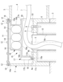
- FIG. 2 is a partial longitudinal sectional view showing a battery holder according to an embodiment of the present disclosure, which is mounted on the electric machine of FIG. 1.
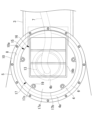
- FIG. 3 is a partial side view of the electric machine of FIG. 2 with the cover removed. 3 is a side view showing the battery holder of FIG. 2.
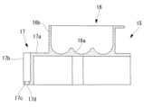
- FIG. 5 is a longitudinal cross-sectional view showing the battery holder of FIG. 4.
- FIG. 4 is a partial side view showing a state in which the battery holder is removed from the electric machine of FIG. 3.
- FIG. FIG. 3 is a partial vertical sectional view showing a modification of the electric machine of FIG. 2;
- the electric machine 1 is a robot (hereinafter also referred to as robot 1).
- the robot 1 includes a base 2 installed on an installation surface A such as a floor, and a movable part 3 such as one or more arms movable with respect to the base 2.
- the base 2 and each movable part 3 are formed hollow and include an outer wall 5 defining an internal space 4, as shown in FIG.
- the robot 1 includes one or more servo motors (not shown) for driving the movable part 3.
- the servo motor is arranged inside the base 2 or inside the internal space 4 of each movable part 3, or outside the outer wall 5. Further, the base 2 and the internal space 4 of each movable part 3 accommodate mechanical parts such as a speed reducer 6 that reduces the rotation of the shaft of the servo motor.
- the interior space 4 also accommodates a cable 7 that supplies power and signals to the servo motor.
- a servo motor rotates a shaft by receiving power from a control device (not shown), and generates heat when energized. Furthermore, mechanical parts such as the reducer 6 may move within the internal space 4 due to the operation of the servo motor. Further, the cable 7 conducts current when driving the servo motor.
- the state of the servo motor, mechanical parts such as the reducer 6, and the cable 7 may change depending on whether or not power is supplied to the servo motor. Therefore, the servo motor, mechanical parts such as the speed reducer 6, and the cable 7 are parts that can be brought into operation by being energized. Furthermore, in addition to the speed reducer 6, all components that may be operated within the internal space 4 by the servo motor are components that can be brought into operation by being energized.
- an opening 8 is formed in the outer wall 5 of the movable part 3 to communicate the internal space 4 with the outside.
- the opening 8 has a large opening equivalent to the outer shape of the reducer 6, for example, in order to enable fastening of the bolt 9 that fixes the reducer 6 in the internal space 4.
- a seat surface 10 is formed around the entire circumference of the opening 8, and a plurality of screw holes 10a are formed in the seat surface 10 along the circumferential direction.
- the robot 1 includes a cover 11 that opens and closes the opening 8.
- the cover 11 can be removably attached to the outer wall 5 by bolts 12 fastened to the screw holes 10a of the seat surface 10.
- a seal member (not shown) is arranged between the seat surface 10 and the cover 11.
- the reducer 6 includes, for example, a hollow hole 6a near the axis C that penetrates along the central axis.
- the cable 7 passes through the hollow hole 6a and is routed from the adjacent base 2 or other movable part 3 into the internal space 4 of the movable part 3.
- a resin cylinder 13 is placed inside the hollow hole 6a, and the cable 7 is passed through the cylinder 13 to protect the cable 7 from contact with the speed reducer 6.
- the cylindrical body 13 is fixed to, for example, a movable part of the reducer 6, and rotates with respect to the movable part 3 by operation of a servo motor. Therefore, the cylindrical body 13 also becomes a component that can be brought into operation when energized.
- the speed reducer 6 since the speed reducer 6 is disposed outside the internal space 4, most of it is not a component that can be activated by energization.
- the movable portion of the reducer 6 exposed to the internal space 4 via the through hole 4b that penetrates the cylindrical body 13 becomes a component that can be brought into operation when energized.
- the cable 7 is fixed to a guide plate (not shown) with a nylon band (not shown) or the like in the internal space 4 so as to form a desired wiring route.
- the servo motor includes a rotary encoder (hereinafter referred to as an encoder, not shown) that detects and stores rotation angle position information of the shaft. When the control device is powered on, the encoder receives power sent via the cable 7 and holds the rotation angle position information without losing it.
- the robot 1 includes a battery holder 15 housed in the internal space 4 of the movable part 3.
- the battery holder 15 according to this embodiment includes a battery accommodating portion 16 and a partition wall 17, as shown in FIGS. 4 and 5.
- the battery accommodating portion 16 is formed in a box shape including a bottom surface 16a and four side walls 16b connected to the bottom surface 16a, and accommodates one or more batteries 14 therein.
- the partition wall 17 includes a flat plate portion 17a extending from the outer surface of the side wall 16b of the battery housing portion 16 in a direction extending the bottom surface 16a of the battery housing portion 16. Further, the partition wall 17 includes a peripheral wall portion 17b extending from the outer peripheral edge of the flat plate portion 17a in a direction intersecting the flat plate portion 17a.
- the battery accommodating portion 16 and the partition wall 17 are integrally manufactured, for example, by injection molding of an electrically insulating resin material.
- the peripheral wall portion 17b includes a mounting portion 17c that is brought into close contact with a seat surface 18 provided on the inner surface 4a of the internal space 4 of the movable portion 3.
- the attachment portion 17c includes a through hole 17d.
- the seat surface 18 is provided on the inner surface 4a of the interior space 4 at a position facing the opening 8, and includes a plurality of screw holes 18a. To fix the battery holder 15 to the movable part 3, the mounting part 17c is brought into close contact with the seat surface 18, and the bolt 19 passed through the through hole 17d is fastened to the screw hole 18a.
- the bottom surface 16a of the battery accommodating part 16 and the partition wall 17 cover the through hole 4b of the movable part 3 and the cable 7.
- the battery accommodating portion 16 and the partition wall 17 block the operator's access path to the hollow hole 6a and the cable 7 via the opening portion 8.
- blocking the access path means closing or narrowing the space so that the operator's hand inserted through the opening 8 cannot pass through.
- FIG. 6 shows a state in which the battery holder 15 is not fixed in the internal space 4.
- the bolt 9, cylindrical body 13, and cable 7 for assembling the reducer 6 are exposed at a position where the operator can freely access them. Therefore, the operator can easily attach and detach the bolts 9 for the reducer 6 or route the cable 7 by using the wide opening 8.
- the battery accommodating portion 16, the partition wall 17, and the inner surface 4a define an isolated space 20, as shown in FIG. Isolation space 20 is located on the opposite side of opening 8 with battery accommodating portion 16 and partition wall 17 in between.
- Isolation space 20 is located on the opposite side of opening 8 with battery accommodating portion 16 and partition wall 17 in between.
- the hollow hole 6a, the cylindrical body 13, and the cable 7 are arranged.
- the partition wall 17 of the battery holder 15 blocks a person's access path to these parts via the opening 8.
- the battery holder 15 is fixed to the inner surface 4a of the internal space 4 of the robot 1, which is opened and closed by the cover 11. This eliminates the need to provide an opening dedicated to the battery holder 15 in the outer wall 5, and also eliminates the need for a dedicated seal structure, resulting in a simple configuration. Since only one cover 11 is required, the number of parts can be reduced, and less machining of the seat surface 10 is required, resulting in cost reduction.
- the battery accommodating portion 16 is located closer to the front side than the isolated space 20 when viewed from the opening 8 side.
- the battery 14 can be easily replaced by removing the cover 11 to open the opening 8 and exposing the battery accommodating part 16. At this time, the access path is blocked by the battery holder 15, thereby preventing the operator from accidentally touching the parts 6, 7, and 13 that can become activated when energized.
- the isolated space 20 and the battery housing section 16 are arranged at positions that overlap in the direction of the axis C of the movable section 3. Thereby, the isolated space 20 is not narrowed by the battery accommodating part 16, and the isolated space 20 in which the cable 7 is routed can be secured widely. As a result, the area of the inner surface 4a necessary for installing the battery holder 15 can be reduced, and the robot 1 can be made smaller.
- the power is cut off and the energization is stopped. Therefore, the battery holder 15 can be removed to form an access path and easily worked through the same opening 8.
- the reducer 6, the cable 7, and the cylindrical body 13 are exemplified as components that can be activated by energization.
- the speed reducer 6 includes a stationary part that does not move relative to the inner surface 4a of the movable part 3, and a part that moves with respect to the stationary part.
- the stationary portion does not need to be covered by the partition wall 17 of the battery holder 15.
- the components that can be brought into operation when energized may include a servo motor that generates heat when energized or a gear that is rotated by the servo motor.
- the robot 1 is illustrated as an example of an electric machine, the present invention is not limited to this.
- the present disclosure can be applied to any electric machine 1 driven by a servo motor including an encoder.
- the isolated space 20 and the battery accommodating portion 16 are arranged to overlap in the direction of the axis C.
- the isolated space 20 and the battery housing section 16 may be arranged side by side in a direction perpendicular to the axis C. Thereby, the dimension of the battery holder 15 in the direction along the axis C can be reduced, and the robot 1 can be downsized in the axis C direction.
- the partition wall 17 has the peripheral wall portion 17b.
- the peripheral wall portion may be provided on the inner surface 4a side of the movable portion 3, and the partition wall 17 may have only the flat plate portion 17a.
- partition wall 17 is integrally molded with the battery accommodating portion 16 is illustrated.
- the partition wall 17 and the battery accommodating portion 16 may be formed separately and then fixed to each other by adhesive, screws, or the like.
- the battery holder 15 is arranged in the internal space 4 of the movable part 3 is illustrated, it may be arranged in the internal space of the base 2. Further, as shown in FIG. 7, a lid 21 that is detachably attached to the battery accommodating portion 16 may be provided. It is preferable that the lid body 21 is removable using a simple mechanism such as a snap fit. By closing the battery accommodating portion 16 with the lid 21, it is possible to more reliably prevent the battery 14 from falling off while the robot 1 is operating.
- any other fall-off prevention means such as a fixing belt (not shown) may be provided. It is preferable that the fixing belt is removable using a simple mechanism such as a hook.
Landscapes
- Engineering & Computer Science (AREA)
- Chemical & Material Sciences (AREA)
- Chemical Kinetics & Catalysis (AREA)
- Electrochemistry (AREA)
- General Chemical & Material Sciences (AREA)
- Robotics (AREA)
- Mechanical Engineering (AREA)
- Manipulator (AREA)
- Battery Mounting, Suspending (AREA)
Abstract
Description
したがって、組立および保守を容易にし、通電により作動状態となり得る部品への接触を回避しつつバッテリ交換できる簡易な構造が望まれている。
本実施形態に係る電動機械1は、図1に示されるように、ロボットである(以下、ロボット1とも言う。)。
また、減速機6等の機械部品は、サーボモータの作動によって、内部空間4内において動く可能性がある。また、ケーブル7は、サーボモータを駆動する際に電流を流す。
サーボモータは、シャフトの回転角度位置情報を検出して記憶するロータリエンコーダ(以下、エンコーダという。図示略)を備えている。エンコーダは、制御装置の電源投入時には、ケーブル7を経由して送られてくる電力の供給を受け、回転角度位置情報を消失することなく保持する。
本実施形態に係るバッテリホルダ15は、図4および図5に示すように、バッテリ収容部16と、隔壁17とを備えている。
隔壁17は、バッテリ収容部16の側壁16bの外面から、バッテリ収容部16の底面16aを延長する方向に延びる平板部17aを備える。また、隔壁17は、平板部17aの外周縁から平板部17aに交差する方向に延びる周壁部17bを備える。
また、本実施形態においては、隔離空間20とバッテリ収容部16とを軸線C方向に重ねて配置した。これに代えて、隔離空間20とバッテリ収容部16とを軸線Cに直交する方向に並べて配置してもよい。これにより、バッテリホルダ15の軸線Cに沿う方向の寸法を低減し、ロボット1を軸線C方向に小型化することができる。
また、図7に示すように、バッテリ収容部16に着脱可能に取り付けられる蓋体21を備えてもよい。蓋体21は、例えば、スナップフィット等の簡易な機構によって着脱可能であることが好ましい。バッテリ収容部16を蓋体21によって閉じることにより、ロボット1の動作中におけるバッテリ14の脱落をより確実に防止することができる。
4 内部空間
4a 内面
5 外壁
6 減速機(部品、機械部品)
7 ケーブル(部品)
8 開口部
11 カバー
13 円筒体(部品)
14 バッテリ
15 バッテリホルダ
16 バッテリ収容部
17 隔壁
21 蓋体
Claims (7)
- サーボモータによって駆動される電動機械のエンコーダのバックアップ用のバッテリを保持するとともに、前記電動機械の外壁の開口部を開閉可能なカバーにより密封される前記電動機械の内部空間内の内面に着脱可能に固定されるバッテリホルダであって、
前記バッテリを収容し、前記開口部が開かれた状態において前記バッテリが取り外し可能となるバッテリ収容部と、
該バッテリ収容部の外方に設けられた隔壁とを備え、
該隔壁が、前記サーボモータへの通電により作動状態になり得る部品への前記開口部を経由したアクセス経路を遮断するバッテリホルダ。 - 通電により作動状態になり得る前記部品が、前記サーボモータに電力を供給するケーブルである請求項1に記載のバッテリホルダ。
- 通電により作動状態になり得る前記部品が、前記サーボモータによって駆動される機械部品である請求項1に記載のバッテリホルダ。
- 通電により作動状態になり得る前記部品が配置される空間が、前記バッテリ収容部および前記隔壁を挟んで前記開口部とは反対側に配置される請求項1から請求項3のいずれかに記載のバッテリホルダ。
- 通電により作動状態になり得る前記部品が配置される空間が、前記バッテリ収容部の周囲の前記隔壁を挟んで前記開口部とは反対側に配置される請求項1から請求項3のいずれかに記載のバッテリホルダ。
- 前記バッテリ収容部を開閉する蓋体を備える請求項1から請求項5のいずれかに記載のバッテリホルダ。
- 内部空間を形成する外壁と、
該外壁に設けられた開口部を開閉可能なカバーと、
前記内部空間内に少なくとも一部が配置され、通電により作動状態になり得る部品と、
請求項1から請求項6のいずれかに記載のバッテリホルダとを備える電動機械。
Priority Applications (6)
| Application Number | Priority Date | Filing Date | Title |
|---|---|---|---|
| PCT/JP2022/021698 WO2023228396A1 (ja) | 2022-05-27 | 2022-05-27 | バッテリホルダおよび電動機械 |
| JP2024522861A JP7783411B2 (ja) | 2022-05-27 | 2022-05-27 | バッテリホルダおよび電動機械 |
| CN202280096121.3A CN119213615A (zh) | 2022-05-27 | 2022-05-27 | 电池座以及电动机械 |
| US18/841,429 US20250167370A1 (en) | 2022-05-27 | 2022-05-27 | Battery holder and electric machine |
| DE112022006535.4T DE112022006535T5 (de) | 2022-05-27 | 2022-05-27 | Batteriehalter und elektrische Maschine |
| TW112117980A TW202413032A (zh) | 2022-05-27 | 2023-05-15 | 電池座及電動機械 |
Applications Claiming Priority (1)
| Application Number | Priority Date | Filing Date | Title |
|---|---|---|---|
| PCT/JP2022/021698 WO2023228396A1 (ja) | 2022-05-27 | 2022-05-27 | バッテリホルダおよび電動機械 |
Publications (1)
| Publication Number | Publication Date |
|---|---|
| WO2023228396A1 true WO2023228396A1 (ja) | 2023-11-30 |
Family
ID=88918821
Family Applications (1)
| Application Number | Title | Priority Date | Filing Date |
|---|---|---|---|
| PCT/JP2022/021698 Ceased WO2023228396A1 (ja) | 2022-05-27 | 2022-05-27 | バッテリホルダおよび電動機械 |
Country Status (6)
| Country | Link |
|---|---|
| US (1) | US20250167370A1 (ja) |
| JP (1) | JP7783411B2 (ja) |
| CN (1) | CN119213615A (ja) |
| DE (1) | DE112022006535T5 (ja) |
| TW (1) | TW202413032A (ja) |
| WO (1) | WO2023228396A1 (ja) |
Citations (6)
| Publication number | Priority date | Publication date | Assignee | Title |
|---|---|---|---|---|
| JPH0624886U (ja) * | 1993-07-29 | 1994-04-05 | ファナック株式会社 | 産業用ロボット |
| JPH10227659A (ja) * | 1997-02-17 | 1998-08-25 | Fanuc Ltd | アブソリュートエンコーダ用電源バックアップ装置 |
| JP2007292608A (ja) * | 2006-04-25 | 2007-11-08 | Fanuc Ltd | アブソリュートエンコーダ用バックアップ電源 |
| JP2008177036A (ja) * | 2007-01-18 | 2008-07-31 | Canon Inc | 電子機器の電池収納構造 |
| JP2011065941A (ja) * | 2009-09-18 | 2011-03-31 | Denso Wave Inc | ロボット用電池格納機構 |
| JP2011198554A (ja) * | 2010-03-18 | 2011-10-06 | Denso Wave Inc | バックアップ用電池収容機構 |
Family Cites Families (1)
| Publication number | Priority date | Publication date | Assignee | Title |
|---|---|---|---|---|
| JPH0567490A (ja) | 1991-09-06 | 1993-03-19 | Matsushita Electric Ind Co Ltd | ヒータユニツト |
-
2022
- 2022-05-27 WO PCT/JP2022/021698 patent/WO2023228396A1/ja not_active Ceased
- 2022-05-27 CN CN202280096121.3A patent/CN119213615A/zh active Pending
- 2022-05-27 US US18/841,429 patent/US20250167370A1/en active Pending
- 2022-05-27 JP JP2024522861A patent/JP7783411B2/ja active Active
- 2022-05-27 DE DE112022006535.4T patent/DE112022006535T5/de active Pending
-
2023
- 2023-05-15 TW TW112117980A patent/TW202413032A/zh unknown
Patent Citations (6)
| Publication number | Priority date | Publication date | Assignee | Title |
|---|---|---|---|---|
| JPH0624886U (ja) * | 1993-07-29 | 1994-04-05 | ファナック株式会社 | 産業用ロボット |
| JPH10227659A (ja) * | 1997-02-17 | 1998-08-25 | Fanuc Ltd | アブソリュートエンコーダ用電源バックアップ装置 |
| JP2007292608A (ja) * | 2006-04-25 | 2007-11-08 | Fanuc Ltd | アブソリュートエンコーダ用バックアップ電源 |
| JP2008177036A (ja) * | 2007-01-18 | 2008-07-31 | Canon Inc | 電子機器の電池収納構造 |
| JP2011065941A (ja) * | 2009-09-18 | 2011-03-31 | Denso Wave Inc | ロボット用電池格納機構 |
| JP2011198554A (ja) * | 2010-03-18 | 2011-10-06 | Denso Wave Inc | バックアップ用電池収容機構 |
Also Published As
| Publication number | Publication date |
|---|---|
| TW202413032A (zh) | 2024-04-01 |
| US20250167370A1 (en) | 2025-05-22 |
| CN119213615A (zh) | 2024-12-27 |
| DE112022006535T5 (de) | 2025-01-23 |
| JPWO2023228396A1 (ja) | 2023-11-30 |
| JP7783411B2 (ja) | 2025-12-09 |
Similar Documents
| Publication | Publication Date | Title |
|---|---|---|
| KR100673575B1 (ko) | 회전 제어회로기판을 구비한 모터 | |
| JP7022091B2 (ja) | ロボット | |
| JP4972420B2 (ja) | 車両用自動開閉装置 | |
| JP2018192607A (ja) | 産業用ロボット | |
| JP2017113873A (ja) | 特にscaraタイプの多軸産業用ロボット | |
| JP7047309B2 (ja) | モータ、電動アクチュエータ | |
| US12187117B2 (en) | Lid opening/closing device | |
| CN111213305A (zh) | 驱动装置 | |
| WO2023228396A1 (ja) | バッテリホルダおよび電動機械 | |
| JP4191861B2 (ja) | パワーウインド装置のモータユニット | |
| US6879073B2 (en) | Electromotive linear drive | |
| JP2001205542A (ja) | 工作機械のカバー装置およびカバー装置の組立方法 | |
| KR20060123245A (ko) | 전기 모터용 스냅―피트 커버플레이트 및 기어하우징 | |
| JP7059551B2 (ja) | 電動アクチュエータ | |
| WO2022168818A1 (ja) | ロボット | |
| US5278469A (en) | Endshield cover assembly for a motor | |
| US10974357B2 (en) | Spindle device | |
| JP4960111B2 (ja) | 車両用自動開閉装置 | |
| JP2004159387A (ja) | モータ | |
| WO2019198830A1 (ja) | インバータユニットおよびモータユニット | |
| JP6977803B2 (ja) | モータ組立体 | |
| JP7189678B2 (ja) | ギヤボックス及びこれを備えた減速機及びモータユニット、並びに、これを製造する金型及びギヤボックスの製造方法 | |
| JP4504080B2 (ja) | 安全スイッチ | |
| JP2008184877A (ja) | 車両用自動開閉装置 | |
| JP4602902B2 (ja) | エンジン冷却ウォータポンプ装置 |
Legal Events
| Date | Code | Title | Description |
|---|---|---|---|
| 121 | Ep: the epo has been informed by wipo that ep was designated in this application |
Ref document number: 22943796 Country of ref document: EP Kind code of ref document: A1 |
|
| ENP | Entry into the national phase |
Ref document number: 2024522861 Country of ref document: JP Kind code of ref document: A |
|
| WWE | Wipo information: entry into national phase |
Ref document number: 18841429 Country of ref document: US |
|
| WWE | Wipo information: entry into national phase |
Ref document number: 112022006535 Country of ref document: DE |
|
| WWE | Wipo information: entry into national phase |
Ref document number: 202280096121.3 Country of ref document: CN |
|
| WWP | Wipo information: published in national office |
Ref document number: 202280096121.3 Country of ref document: CN |
|
| WWP | Wipo information: published in national office |
Ref document number: 18841429 Country of ref document: US |
|
| 122 | Ep: pct application non-entry in european phase |
Ref document number: 22943796 Country of ref document: EP Kind code of ref document: A1 |