WO2023224068A1 - 浄化装置 - Google Patents
浄化装置 Download PDFInfo
- Publication number
- WO2023224068A1 WO2023224068A1 PCT/JP2023/018443 JP2023018443W WO2023224068A1 WO 2023224068 A1 WO2023224068 A1 WO 2023224068A1 JP 2023018443 W JP2023018443 W JP 2023018443W WO 2023224068 A1 WO2023224068 A1 WO 2023224068A1
- Authority
- WO
- WIPO (PCT)
- Prior art keywords
- air
- incubator
- section
- purification device
- ethanol
- Prior art date
- Legal status (The legal status is an assumption and is not a legal conclusion. Google has not performed a legal analysis and makes no representation as to the accuracy of the status listed.)
- Ceased
Links
Images



Classifications
-
- A—HUMAN NECESSITIES
- A61—MEDICAL OR VETERINARY SCIENCE; HYGIENE
- A61G—TRANSPORT, PERSONAL CONVEYANCES, OR ACCOMMODATION SPECIALLY ADAPTED FOR PATIENTS OR DISABLED PERSONS; OPERATING TABLES OR CHAIRS; CHAIRS FOR DENTISTRY; FUNERAL DEVICES
- A61G11/00—Baby-incubators; Couveuses
-
- A—HUMAN NECESSITIES
- A61—MEDICAL OR VETERINARY SCIENCE; HYGIENE
- A61G—TRANSPORT, PERSONAL CONVEYANCES, OR ACCOMMODATION SPECIALLY ADAPTED FOR PATIENTS OR DISABLED PERSONS; OPERATING TABLES OR CHAIRS; CHAIRS FOR DENTISTRY; FUNERAL DEVICES
- A61G10/00—Treatment rooms or enclosures for medical purposes
- A61G10/02—Treatment rooms or enclosures for medical purposes with artificial climate; with means to maintain a desired pressure, e.g. for germ-free rooms
-
- A—HUMAN NECESSITIES
- A61—MEDICAL OR VETERINARY SCIENCE; HYGIENE
- A61G—TRANSPORT, PERSONAL CONVEYANCES, OR ACCOMMODATION SPECIALLY ADAPTED FOR PATIENTS OR DISABLED PERSONS; OPERATING TABLES OR CHAIRS; CHAIRS FOR DENTISTRY; FUNERAL DEVICES
- A61G11/00—Baby-incubators; Couveuses
- A61G11/009—Baby-incubators; Couveuses with hand insertion windows, e.g. in the walls
-
- A—HUMAN NECESSITIES
- A61—MEDICAL OR VETERINARY SCIENCE; HYGIENE
- A61M—DEVICES FOR INTRODUCING MEDIA INTO, OR ONTO, THE BODY; DEVICES FOR TRANSDUCING BODY MEDIA OR FOR TAKING MEDIA FROM THE BODY; DEVICES FOR PRODUCING OR ENDING SLEEP OR STUPOR
- A61M16/00—Devices for influencing the respiratory system of patients by gas treatment, e.g. ventilators; Tracheal tubes
- A61M16/10—Preparation of respiratory gases or vapours
- A61M16/105—Filters
-
- B—PERFORMING OPERATIONS; TRANSPORTING
- B01—PHYSICAL OR CHEMICAL PROCESSES OR APPARATUS IN GENERAL
- B01D—SEPARATION
- B01D53/00—Separation of gases or vapours; Recovering vapours of volatile solvents from gases; Chemical or biological purification of waste gases, e.g. engine exhaust gases, smoke, fumes, flue gases, aerosols
- B01D53/02—Separation of gases or vapours; Recovering vapours of volatile solvents from gases; Chemical or biological purification of waste gases, e.g. engine exhaust gases, smoke, fumes, flue gases, aerosols by adsorption, e.g. preparative gas chromatography
- B01D53/04—Separation of gases or vapours; Recovering vapours of volatile solvents from gases; Chemical or biological purification of waste gases, e.g. engine exhaust gases, smoke, fumes, flue gases, aerosols by adsorption, e.g. preparative gas chromatography with stationary adsorbents
-
- B—PERFORMING OPERATIONS; TRANSPORTING
- B01—PHYSICAL OR CHEMICAL PROCESSES OR APPARATUS IN GENERAL
- B01D—SEPARATION
- B01D53/00—Separation of gases or vapours; Recovering vapours of volatile solvents from gases; Chemical or biological purification of waste gases, e.g. engine exhaust gases, smoke, fumes, flue gases, aerosols
- B01D53/02—Separation of gases or vapours; Recovering vapours of volatile solvents from gases; Chemical or biological purification of waste gases, e.g. engine exhaust gases, smoke, fumes, flue gases, aerosols by adsorption, e.g. preparative gas chromatography
- B01D53/04—Separation of gases or vapours; Recovering vapours of volatile solvents from gases; Chemical or biological purification of waste gases, e.g. engine exhaust gases, smoke, fumes, flue gases, aerosols by adsorption, e.g. preparative gas chromatography with stationary adsorbents
- B01D53/0407—Constructional details of adsorbing systems
- B01D53/0446—Means for feeding or distributing gases
-
- B—PERFORMING OPERATIONS; TRANSPORTING
- B01—PHYSICAL OR CHEMICAL PROCESSES OR APPARATUS IN GENERAL
- B01D—SEPARATION
- B01D2253/00—Adsorbents used in seperation treatment of gases and vapours
- B01D2253/10—Inorganic adsorbents
- B01D2253/102—Carbon
-
- B—PERFORMING OPERATIONS; TRANSPORTING
- B01—PHYSICAL OR CHEMICAL PROCESSES OR APPARATUS IN GENERAL
- B01D—SEPARATION
- B01D2257/00—Components to be removed
- B01D2257/70—Organic compounds not provided for in groups B01D2257/00 - B01D2257/602
- B01D2257/708—Volatile organic compounds V.O.C.'s
-
- B—PERFORMING OPERATIONS; TRANSPORTING
- B01—PHYSICAL OR CHEMICAL PROCESSES OR APPARATUS IN GENERAL
- B01D—SEPARATION
- B01D2259/00—Type of treatment
- B01D2259/45—Gas separation or purification devices adapted for specific applications
- B01D2259/4533—Gas separation or purification devices adapted for specific applications for medical purposes
Definitions
- the present invention relates to a purification device that purifies air by removing volatile substances vaporized during medical intervention.
- volatile substances may be used as alcohols for disinfection purposes or to disinfect the hands of those performing medical procedures, or as solvents for medicines.
- alcohols used for disinfection include ethanol, isopropanol, and the like. If such a volatile substance is used in an incubator and vaporizes, there is a risk that the patient in the incubator will be exposed to the volatile substance for a long period of time. For example, ethanol and isopropanol can have a negative impact on the child's body and growth. Therefore, when using ethanol in medical treatment for a patient in an incubator, it is necessary to suppress the increase in the concentration of volatile substances in the air within the incubator.
- An object of the present disclosure is to provide a purification device that can sufficiently remove volatile substances such as volatile substances floating around a patient in an incubator.
- a purification device is a purification device that is disposed in a storage chamber for accommodating a patient in an incubator and purifies the air in the storage chamber, and includes an intake section for taking in the air, and a purification device for purifying the air in the storage chamber.
- a suction unit that sucks out volatile substances
- a removal unit that removes volatile substances that are substances used in medical intervention for the patient from the air sucked by the suction unit, and air from which the volatile substances have been removed by the removal unit. It is equipped with an exhaust section that exhausts the air.
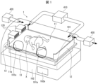
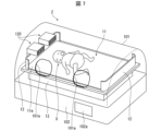
- FIG. 1 is a schematic perspective view of an incubator equipped with a purification device according to Embodiment 1 of the present disclosure.
- 2 is a schematic perspective view of an incubator showing another example of the incubator shown in FIG. 1.
- FIG. FIG. 2 is a schematic plan view of the volatile substance removal device shown in FIG. 1.
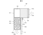
- FIG. FIG. 4 is a cross-sectional view taken along the line AA of the volatile substance removal device shown in FIG. 3;
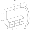
- FIG. 7 is a schematic perspective view showing a modification of the purification device according to Embodiment 2 of the present disclosure.
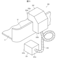
- FIG. 7 is a schematic perspective view showing another modification of the purification device according to Embodiment 2 of the present disclosure.
- FIG. 7 is a schematic cross-sectional view of the purification device shown in FIG. 6.
- 2 is a schematic cross-sectional view of the incubator shown in FIG. 1.
- FIG. 1 is a schematic perspective view of an incubator equipped with a purification device according to Embodiment 1 of the present disclosure.
- a purification device is installed within the incubator to adsorb and remove volatile substances contained in the air within the incubator.
- the volatile substances adsorbed and removed by the purification device are substances used in medical intervention for patient X, such as ethanol.
- the purification device installed within the incubator thus removes ethanol, a volatile substance used in medical interventions performed within the incubator, from the air within the incubator. This can improve the safety of performing medical intervention on a patient in the incubator.
- the reason why the purifying device is installed in the incubator is that problems are unlikely to occur in terms of hygiene or functionality.
- condensation may occur due to the difference in temperature and humidity between the inside and outside of the incubator, which tends to cause problems in terms of hygiene and functionality.
- ethanol will be explained as an example of a volatile substance to be removed, but the present invention is not limited to this.
- FIG. 1 is a schematic perspective view of the incubator 1.
- the incubator 1 includes a storage chamber 101 that accommodates the patient X, and a mounting table 102 on which the storage chamber 101 is placed. Inside the storage room 101, a bed 11 and screen sections 12 are arranged in front and behind the bed.
- the surface 11a of the bed 11 is a placement surface on which the patient is placed.
- the bed 11 is installed on a bed stage 13 provided on a mounting table 102.
- the bed stage 13 can move the bed 11 in the vertical direction or in the vertical and horizontal directions.
- the screen portion 12 is made of transparent resin and has a predetermined height and a predetermined width from the surface 11a of the bed 11.
- the screen section 12 is made of transparent resin and has a predetermined height and a predetermined width from the surface 11a of the bed 11, and is also used as an installation section for installing a purification device 120, which will be described later.
- the storage room 101 is provided with two treatment openings 101a through which a doctor or nurse can administer treatment such as intravenous administration to the patient X.
- treatment such as intravenous administration to the patient X.
- it is necessary to disinfect the room.
- alcohol cotton is used to disinfect the area to be treated, such as the hands of patient X.
- ethanol is generated in the storage chamber 101.
- two purifying devices 120 are arranged in the storage chamber 101 on the screen section 12 of the bed 11.
- the air in the storage chamber 101 includes first air located away from the source that emits ethanol (for example, alcohol cotton) and second air near the source that emits ethanol (for example, alcohol cotton). Therefore, the purifier 120 mainly removes ethanol from the first air located away from the ethanol source.
- the purifier 120 is disposed within the storage chamber 101 and constitutes a removal section that removes ethanol from the air within the storage chamber 101.
- the incubator 1 is an incubator (so-called closed incubator) equipped with a storage chamber whose internal temperature and humidity can be adjusted to accommodate a patient.
- the incubator 1 further includes a circulation section 410, a supply section 420, and a discharge section 430.
- the circulation unit 410 circulates temperature- and humidity-controlled air into the storage chamber 101 .
- the supply unit 420 supplies air from outside the storage chamber 101 into the storage chamber 101 .
- the discharge unit 430 discharges at least a portion of the air within the storage chamber 101 to the outside of the storage chamber 101 .
- the incubator 1 is ventilated by performing natural intake and exhaust at a level at which the temperature and humidity can be maintained.
- the incubator 1 may be able to adjust not only the temperature and humidity but also the oxygen concentration.
- An operation panel 102a is provided on the mounting table 102 so that a user (a doctor, a nurse, etc.) can operate the functions of the incubator 1.
- the temperature and humidity of the air in the storage chamber 101 are adjusted by the circulation unit 410. Further, the purifier 120 takes in air in the storage chamber 101, removes ethanol contained in the taken-in air, and exhausts the air from which ethanol has been removed into the storage chamber 101 again. Thereby, ethanol can be removed from the storage chamber 101 while maintaining the temperature and humidity inside the storage chamber 101.
- Another possible method is to remove the ethanol in the air outside the incubator 1 and replace the air outside the incubator 1 with the air inside the incubator 1, but this method does not maintain the temperature and humidity inside the incubator 1. difficult.
- FIG. 2 is a schematic perspective view of the purification device 120.
- 3 is a sectional view taken along the line AA in FIG. 2.
- FIG. 2 is a schematic perspective view of the purification device 120.
- the purification device 120 includes two integrally provided casings (a first casing 121 and a second casing 122).
- first casing 121 and second casing 122 are connected to form one casing.
- the two casings may be integrally molded to form one casing.
- the front surface 121a of the first housing 121 is provided with an intake section 121b that takes in outside air.
- the first casing 121 has a structure in which the rear part including the rear surface of the first casing 121 is internally communicated with the second casing 122 at the bottom surface 121c of the first casing 121. The outside air is guided to the second casing 122.
- the rear part of the first housing 121 is located downstream of the front surface 121a in the direction from the intake part 121b to the exhaust part 122b (hereinafter referred to as the exhaust direction).
- the front surface 121a is located upstream of the rear part of the first housing 121 in the exhaust direction.
- the front surface of the second housing 122 is a rear portion including the rear surface of the first housing 121, and is connected to the lower surface 121c of the first housing 121.
- An exhaust section 122b (FIG. 3) for exhausting outside air is provided on the rear surface 122a of the second housing 122 (the surface opposite to the communication side with the first housing 121).
- the front surface of the second housing 122 is located upstream of the rear surface 122a in the exhaust direction.
- the rear surface 122a is located downstream of the second housing 122 in the exhaust direction.
- the purifier 120 has an inverted L-shaped cross section and is installed in the screen section 12 in the storage chamber 101. That is, the purifying device 120 is installed above the mounting surface.
- the purifier 120 is provided with a fixing part for fixing the first casing 121 and the second casing 122 to the inner edge of the storage chamber 101.
- a protrusion protruding downward as a fixing part is provided parallel to the side surface 122c of the second housing 122 and at a predetermined distance from the side surface 122c.
- a portion 121d is provided.
- the protrusion 121d is a member made of, for example, resin and has a predetermined height and a predetermined width, and is provided integrally with the first housing 121.
- FIG. 3 shows an example in which a protrusion 121d is connected to the first casing 121 to form one casing. Note that the first housing 121 and the protrusion 121d may be integrally molded to form one housing.
- the protruding portion 121d is provided at a position where the distance between the protruding portion 121d and the side surface 122c of the second housing 122 is slightly longer than the thickness of the screen portion 12 of the storage chamber 101.
- the first casing 121 and the second casing 122 can be fixed to the screen section 12, which is a wall section erected at the inner edge of the storage chamber 101, by the protruding section 121d.
- the first casing 121 and the second casing 122 that is, the main body of the purifying device 120
- the protrusion 121d which is a fixing part.
- the purifying device 120 does not interfere with medical treatment for the patient X in the incubator 1.
- the protrusion 121d may be configured to be detachable from the screen 12 provided at the inner edge of the storage chamber 101.
- the purification device 120 is preferably installed in a position where it does not interfere with medical procedures.
- the exhaust direction of the purifier 120 (the direction in which air from which ethanol has been removed is exhausted) is preferably a direction that does not inhibit the circulation of air within the incubator 1 and that does not hit the patient X.
- the incubator 1 maintains its functions (temperature/humidity maintenance function, etc.), and the air hits the patient X, thereby depriving the patient of body heat and promoting water loss through insensible evaporation. Since there is no such thing, the safety of patient X can be ensured.
- the protrusion 121d provided on the first housing 121 is continuously provided in the width direction of the first housing 121 (the direction perpendicular to the exhaust direction within the first housing 121). I'm doing it.
- the first housing 121 includes a first removing section 124 and a suction section 125.
- the first removal section 124 is made of fibrous activated carbon, and quickly adsorbs most of the ethanol contained in the outside air taken in from the intake section 121b. Therefore, if the amount of ethanol contained in the outside air is small, all of the ethanol will be adsorbed in the first removal section 124.
- sheet-like activated carbon obtained by molding fibrous activated carbon into a sheet is used.
- the first removal unit 124 is a cartridge type in which a sheet-like activated carbon is housed in a container that can be attached and detached from the upper side of the first housing 121. This makes it easy to replace the first removal section 124. Furthermore, sheet-shaped activated carbon is disposable. Therefore, the first removal section 124 is replaced as follows. The sheet-like activated carbon stored in the first removing section 124 taken out from the first housing 121 is discarded, a new sheet-like activated carbon is stored in the first removing section 124, and the first removing section 114 is removed from the first removing section 124 again. It is attached to the housing 121.
- the suction unit 125 is composed of one sirocco fan, sucks outside air from the intake unit 121b via the first removal unit 124, and sends the air to the second removal unit 126 at the rear stage in a direction perpendicular to the rotational axis direction of the fan. do.
- the intake air amount in the suction section 125 is set to be 50 L/min or more, but is not limited to this. Note that it is preferable that the suction area of the suction part 125 be large so that a large amount of air can be taken in.
- the second housing 122 includes a second removing section 126.
- the second removing unit 126 is a cartridge type in which pellet-shaped activated carbon is housed in a cartridge that is removable from the second housing 122 . Thereby, the second removal section 126 can be easily replaced.
- pellet-like activated carbon is disposable, the pellet-like activated carbon stored in the second removing section 126 taken out for replacement is discarded, a new pellet-like activated carbon is stored, and the pellet-like activated carbon is placed in the second removing section 126 again. 126 is attached to the second housing 122.
- the exhaust direction of the air (ethanol-removed air) exhausted from the exhaust section 122b of the purifier 120 configured as described above is set in a direction that does not inhibit the circulation of air within the incubator 1.
- the incubator 1 includes, for example, a water tank 17, a heating section 18, a heater 19, and a fan 20, as shown in FIG.
- Water tank 17 contains water.
- the heating unit 18 is provided in the water tank 17 and generates steam by heating the water contained in the water tank 17. Steam generated by the heating unit 18 is circulated within the storage chamber 101 by a fan 20.
- the purifier 120 is fixed to the screen section 12 provided on the bed 11, and takes in the air in the storage chamber 101 through the intake section 121b and exhausts it through the exhaust section 122b.
- the air exhausted from the exhaust part 122b is exhausted to the lower part of the bed 11 through the gap between the screen part 12 of the bed 11 of the incubator 1 and the inner wall surface of the accommodation chamber 101.
- the air exhausted to the lower part of the bed 11 (air from which ethanol has been removed) is taken in by the fan 20 together with the steam generated in the heating section 18 . Therefore, the exhaust direction of the purifier 120 matches the intake direction of the incubator 1.
- the incubator 1 air circulating within the incubator 1 is sucked into the lower part of the bed 11 through a gap between the screen portion 12 of the bed 11 and the inner wall surface of the accommodation chamber 101. Therefore, it is preferable to install the purifying device 120 on the screen 12 of the bed 11 if there is sufficient clearance between the screen 12 of the bed 11 and the inner wall surface of the accommodation chamber 101. Thereby, the exhaust direction of the purifier 220 and the circulation direction of the air circulated within the incubator 1 can be made the same.
- the first removing unit 124 in the first housing 121 uses sheet-like activated carbon as an adsorbent to quickly adsorb a large amount of highly concentrated ethanol, and the first removing unit 124 in the second housing 122
- the second removal section 126 uses pellet-shaped activated carbon as an adsorbent to slowly and thoroughly adsorb the ethanol that has not been completely adsorbed by the first removal section 114 .
- the first removing section 124 is arranged closer to the intake section 121b than the second removing section 126.
- the air sucked from the intake section 121b is Ethanol is removed by the first removal part 124 arranged on the side close to the part 121b (upstream side of the air flow), and then the ethanol is removed by the second removal part 126 arranged on the downstream side of the air flow. Therefore, the ethanol that was not removed by the first removal section 124 can be removed by the second removal section 126.
- One of the conditions for realizing the adsorption properties of the sheet-like activated carbon used in the first removal section 124 described above is that the surface area that comes into contact with the suctioned air is large.
- the purifying device 120 is installed within the storage chamber 101 of the incubator 1, as shown in FIG. In this way, by installing the purification device 120 inside the storage chamber 101, ethanol can be removed from the air inside the storage chamber 101. Thereby, it is possible to prevent the patient X in the storage chamber 101 of the incubator 1 from being unintentionally exposed to ethanol.
- the purification device 120 takes in the air in the storage chamber 101 and transfers the air from which a large amount of ethanol has been quickly removed by the first removal unit 124 of the first casing 121 to the second casing 122.
- the air from which all ethanol has been removed by the second removing section 126 is exhausted into the storage chamber 101. Thereby, ethanol can be removed from the storage chamber 101 while maintaining the temperature and humidity inside the storage chamber 101.
- the purification device 120 was described in which the first casing 121 including the suction section 125 and the second casing 122 including the second removing section 126 were integrated. In this case, even if each housing is slimmed down, it is difficult to slim down the fan that constitutes the suction section 125 included in the first housing 121. It may be difficult to install it on the screen section 12 of the bed 11. Therefore, in Embodiment 2 below, even if the space between the screen part 12 of the bed 11 in the incubator 1 and the storage chamber 101 is small, purified air can be exhausted to the bed 11. The device will be explained.
- FIG. 4 is a schematic perspective view of the purification device 220 according to this embodiment.
- the purification device 220 has almost the same structure as the purification device 120 of the first embodiment, except for the structure for exhausting outside air from which ethanol has been removed.
- the correspondence between each element constituting the purification device 220 and each element constituting the purification device 120 of the first embodiment is as follows.
- the first housing 221 corresponds to the first housing 121
- the second housing 222 corresponds to the second housing 122
- the front surface 221a corresponds to the front surface 121a
- the intake part 221b corresponds to the intake part 121b
- the upper surface 221c corresponds to the lower surface 121c.
- the first housing 221 includes the first removing section 124 and the suction section 125 inside
- the second housing 222 has the first removing section 124 and the suction section 125 inside, like the second housing 122.
- a second removing section 126 is provided.
- the outside air after adsorbing ethanol is exhausted from a tube 223 provided on the side surface 222a.
- the tube 223 is a flexible tube having a predetermined length, and allows the exhaust port 223a to be directed in a desired direction.
- the purifying device 220 having the above configuration is placed under the bed 11 of the accommodation chamber 101 with the first casing 221 facing downward, and the exhaust port 223a of the tube 223 is also placed under the bed 11.
- the exhaust port 223a is arranged so that the direction in which the air is exhausted, that is, the direction in which the air is exhausted, is the same as the direction in which the air circulates within the storage chamber 101.
- the purification device 220 can suck air containing ethanol under the bed 11 and circulate the air from which ethanol has been removed under the bed 11 into the accommodation chamber 101.
- the purifying device 220 is used by being placed under the bed 11, it is possible to increase the size of the fan in the suction unit 125, and it is possible to increase the suction force. In other words, it is possible to increase the suction force by increasing the size of the fan in the suction unit 125 within the range in which the purifying device 220 can be placed in the space under the bed 11 in the accommodation chamber 101. If the purifying device 220 is placed under the bed 11 in this manner, it is not necessary to install the purifying device 220 on the screen portion 12 of the bed 11. Therefore, the purifier 220 is installed under the bed 11 when the gap between the screen 12 of the bed 11 and the inner peripheral surface of the storage chamber 101 is not large, that is, the purifier 220 is installed under the screen 12. Suitable for cases where space is difficult.
- FIG. 5 is a perspective view of the purification device 230 according to this embodiment.
- FIG. 6 is a schematic cross-sectional view of the purification device shown in FIG. 5.
- a configuration like the purification device 230 may be used.
- the purifier 230 has a structure in which a first casing 231 and a second casing 232 are separated and connected by a tube 233.
- the first casing 231 of the purifying device 230 corresponds to the first casing 221 of the purifying device 220, and the second casing 232 corresponds to the second casing 222.
- the first housing 231 includes a suction section 125, sucks air from the front surface 231a, and exhausts air from the rear surface 231b side.
- An opening (not shown) communicating with the inside of the first casing 231 is formed in the front surface 231a of the first casing 231, and a tube 233 is connected to this opening.
- This tube 233 is the same as the tube 223 of the purifier 220 shown in FIG.
- the second housing 232 has a substantially L-shaped cross section and includes a first removing section 124 and a second removing section 126, and allows air introduced from the front surface 232a to be passed through the first removing section 124 and the second removing section 126. and exhaust air from the rear surface 232b.
- An opening (not shown) communicating with the inside of the second housing 232 is formed in the rear surface 232b of the second housing 232, and a tube 233 is connected to this opening. Therefore, air exhausted from the second housing 232 is sucked by the first housing 231 through the tube 233.
- the first removing section 124 adsorbs ethanol using the same sheet-like activated carbon as the first removing section 124 of the first embodiment, and the second removing section 126 is similar to the second removing section 126 of the first embodiment. Ethanol is adsorbed using the same pelleted activated carbon. Furthermore, in order to remove ethanol, the first removing section 124 and the second removing section 126 may not only adsorb ethanol using an adsorbent but also decompose ethanol using a catalyst.
- the first casing 231 is installed below the bed 11, that is, below the placement surface, and the second casing 232 is installed above the screen portion 12 of the bed 11, ie, above the placement surface.
- the side surface 232d of the second housing 232 is installed close to the screen portion 12.
- a protrusion similar to the protrusion 121d described in the first embodiment is provided on the lower surface 232c of the upper side of the second casing 232, and the second casing 232 is fixed to the screen section 12 by this protrusion. Therefore, in the state shown in FIG.
- the purifier 230 takes in air containing ethanol from the front surface 232a of the second casing 232, and the first removing section 124 and the second removing section 126 in the second casing 232
- the air from which ethanol has been removed is suctioned by the suction section 125 of the first housing 231 through the tube 233, and is exhausted from the rear surface 231b of the first housing 231 into the space under the bed 11.
- the housing size of the first housing 231 including the suction section 125 is not limited to the size between the screen section 12 and the peripheral wall of the storage chamber 101 of the incubator 1, and the suction
- the size of the portion 125 the size of the fan can be increased and the amount of suction can be increased.
- the sizes of the first removing section 124 and the second removing section 126 in the second housing 232 can be increased, making it possible to improve the amount of ethanol adsorbed and the durability of the adsorbent.
- the corner of the bent portion of the second housing 232 (the portion facing the intersection of the lower surface 232c and the side surface 232d) is chamfered. Thereby, the range in which the second housing 232 is swung between the screen portion 12 and the peripheral wall of the storage chamber 101 can be expanded.
- the purifiers 120, 220, and 230 of the first, second, and third embodiments drive and stop the fan in the internal suction section 125 by turning the power on and off.
- This power source may be a battery (primary battery, rechargeable battery, etc.), an external power source, or a combination of an external power source and a rechargeable battery. If the purification device is installed in the incubator each time it is used, a battery is preferable as the power source, and if the purification device is always installed in the incubator, an external power source is preferable. Normally, when the purifying device is permanently installed in an incubator and operated continuously, an external power source is preferably used as the power source.
- the fan of the suction unit 125 is driven by turning on the power by the person performing the treatment (doctor or nurse).
- the suction force in the purifiers 120, 220, and 230 can be adjusted by the rotation speed of the fan in the suction section 125, so by changing the fan rotation speed according to the concentration of ethanol to be removed, the suction force can be adjusted appropriately. Ethanol can be aspirated and removed.
- the purifying devices 120, 220, and 230 of the first, second, and third embodiments each have a function of displaying the operating status (driving status).
- the function that displays the operating status includes whether the machine is running, whether it is stopped, whether the filter (activated carbon in the removal section) needs to be replaced, whether a problem has occurred, and whether the battery is low. Indicates that the information such as whether the In this case, the driving status may be displayed on the display panel or by lighting a lamp according to the driving status. Thereby, the treating person can avoid forgetting to operate the purifying devices 120, 220, and 230.
- the purifiers 120, 220, and 230 can display a message prompting the user to replace the filter.
- the purifying devices 120, 220, and 230 of the first, second, and third embodiments are preferably easy to take in and out of the opening 101a of the incubator 1, and have a mass (for example, 150 g) that is easy to handle.
- FIG. 1 An example is shown in which two purifying devices 120 are arranged on one side of the bed 11 (on the head side of the patient X), but the present invention is not limited to this. If ethanol can be removed properly without interfering with medical procedures, two purification devices 120 may be placed on the opposite side (on the foot side of patient X), or one purification device 120 may be placed on both sides of the bed 11. They may be placed separately. The number of purifiers 120 installed may be one, or three or more.
- the protrusion 121d is provided integrally with the first casing 121, but the invention is not limited to this, and the protrusion 121d is provided separately from the first casing 121. may be provided.
- the protrusion 121d provided on the first housing 121 is continuous in the width direction of the first housing 121 (direction perpendicular to the exhaust direction in the first housing 121).
- the filters are provided intermittently, they are not limited to this, and may be provided intermittently.
- one protrusion 121d may be provided at each end of the lower surface 121c of the first housing 121 in the width direction (direction perpendicular to the exhaust direction within the first housing 121).
- the shape of the protruding portion 121d is not particularly limited, and may be any shape that allows the screen portion 12 to be sandwiched between the side surfaces 122c of the second housing 122.
- the protrusion 121d may be movable so as to adjust the distance from the protrusion 121d to the side surface 122c of the second housing 122, depending on the thickness of the screen 12.
- the adsorbent used in the first removing section 124 is an example of activated carbon in the form of a sheet.
- the present invention is not limited to this, and other adsorbents may be used as long as they adsorb ethanol. May be used.
- the direction of the outside air flowing from the suction section 125 to the second removal section 126 is perpendicular to the direction of the outside air flowing from the first removal section 124 to the suction section 125.
- a sirocco fan that blows air in a direction perpendicular to the direction
- the present invention is not limited to this.
- the type of fan may be changed depending on the structure of the first housing 121 and the second housing 122. For example, if the suction direction and the exhaust direction in the first housing 121 are the same, an axial fan may be used.
- the number of fans used in the suction section 125 is not limited to two, and may be one or three or more. Therefore, the type and number of fans are selected in consideration of the power source system, power consumption, required flow rate, etc. used in the purification device.
- the adsorbent used in the second removal section 126 is described as an example of activated carbon in the form of pellets.
- the present invention is not limited to this, and other adsorbents may be used as long as they adsorb ethanol. May be used.
- each of the first removing section 124 and the second removing section 126 may be provided with an adsorbent and a catalyst, so that the adsorbent adsorbs ethanol and the catalyst decomposes ethanol in one removing section.
- the first removing section 124 may decompose ethanol using a catalyst
- the second removing section 126 may adsorb ethanol using an adsorbent
- the first removing section 124 may adsorb ethanol using an adsorbent
- the second removing section 124 may adsorb ethanol using an adsorbent.
- the section 126 may decompose ethanol using a catalyst.
- the objects to be adsorbed or decomposed may be different in the first removing section 124 and the second removing section 126.
- the first removal section 124 may adsorb or decompose volatile substances other than ethanol
- the second removal section 126 may adsorb or decompose ethanol
- the first removal section 124 may adsorb or decompose volatile substances other than ethanol
- the second removal unit 126 may adsorb or decompose volatile substances other than ethanol.
- the first removing section 124 and the second removing section 126 may be replaceable.
- the exhaust port 223a of the tube 223 of the purifying device 220 is installed under the bed 11, but the present invention is not limited to this.
- the installation position of the exhaust port 223a of the tube 223 of the purifier 220 may be such that the air is exhausted to a location that does not affect the patient X on the bed 11 and a location that has little effect on the circulation within the incubator 1. Anywhere is fine.
- the installation position of the exhaust port 223a of the tube 223 in the purifier 220 may be any position as long as the air exhausted from the exhaust port 223a is not directly blown onto the patient on the bed 11.
- the exhaust port 223a of the tube 223 may be installed above the bed 11 if the air is exhausted toward the surrounding walls forming the accommodation chamber 101.
- the purifying device 220 is placed under the bed 11, but the position of the purifying device 220 is not limited to this.
- the purifier 220 may be installed on the screen portion 12 of the bed 11.
- the second housing 222 is installed with the first housing 221 facing upward and the side surface 222b of the second housing 222 close to the screen portion 12.
- a protrusion similar to the protrusion 121d described in the first embodiment is provided on the upper surface 221c of the first housing 221, and the purifying device 220 is fixed to the screen 12 by this protrusion.
- the tube 223 is installed so that the exhaust port 223a of the tube 223 of the purifier 220 faces the space under the bed 11.
- a flexible tube such as the tube 223 included in the purifier 220 in FIG. 4 is provided between the first housing 221 and the second housing 222, and the outside air sucked by the first housing 221 is , may be sent to the second housing 222 via a flexible tube.
- the flexible Just set the length of the tube.
- the second casing 222 is difficult to downsize.
- the first housing 221 is placed under the bed 11, and only the second housing 222, which can be easily miniaturized, is installed on the screen portion 12.
- the corners of the bent portions of the first casing 121 of the first embodiment and the second casing 222 of the second embodiment may be chamfered.
- the range in which the first casing 121 and the second casing 222 are swung between the screen portion 12 and the peripheral wall of the storage chamber 101 is limited. Can be expanded.
- drive control is performed by turning the power on and off, but the invention is not limited to this.
- a concentration sensor that detects the concentration of ethanol may be installed in the storage chamber 101, and the purifiers 120, 220, and 230 may be driven and controlled based on the detection signal from the concentration sensor. For example, when the concentration of ethanol indicated by the detection signal of the concentration sensor exceeds a predetermined concentration, the fan of the suction unit 125 is started to drive, and when the concentration falls below the predetermined concentration, the fan of the suction unit 125 is stopped. You may also do so.
- the rotation speed of the fan in the suction unit 125 is increased. In this way, the suction force may be increased to more actively suck the ethanol in the storage chamber 101. Thereby, ethanol can be quickly suctioned and removed.
- the purifying devices 120, 220, and 230 may be provided with a detection means for detecting the adsorption state of the first removal section 124 and the second removal section 126.
- the detection means may be a concentration sensor that detects ethanol concentration.
- the purifiers 120, 220, and 230 determine the adsorption state (breakthrough (adsorption exceeds the adsorption function, Determine whether the target is leaking (or whether the target is being absorbed sufficiently).
- the detection means may be provided within the purification devices 120, 220, and 230, or may be provided outside the purification devices 120, 220, and 230; and the second removing portion 126). By doing so, it is possible to detect the adsorption state of the first removal section 124. For example, when the adsorption function of the first removal section 124 is reduced and the adsorption function is not sufficiently exerted, or when the second removal section 126 is It becomes possible to replace the first removal section 124 before the adsorption amount increases and the second removal section 126 reaches a breakthrough state. Further, a detection means may be provided downstream of the second removal section 126 to detect the adsorption state of the second removal section 126.
- detection means may be provided both between the first removing section 124 and the second removing section 126 and on the downstream side of the second removing section 126, so that the adsorption state of both the first removing section 124 and the second removing section 126 is may be detected.
- the drive control of the purifiers 120, 220, and 230 is performed by combining the detection results of a concentration sensor provided in the storage chamber 101 that detects the ethanol concentration and the detection results of the detection means that detects the adsorption state. It's okay.
- a detection means may be provided upstream of the first removal section 124.
- the detection means detects the ethanol concentration contained in the air before the ethanol is adsorbed by the first removal unit 124. That is, the detection means detects the concentration of ethanol contained in the air within the incubator 1.
- the drive of the fan of the suction unit 125 may be controlled based on the ethanol concentration detected by the detection means.
- control units (not shown) of the purification devices 120, 220, and 230 control the drive of the motor that rotates the fan of the suction unit 125 according to the ethanol concentration detected by the detection means. For example, if the ethanol concentration detected by the detection means is higher than a predetermined value, the control section controls the drive of the motor to increase the rotation speed of the fan; If it is below, the drive of the motor is controlled to lower the rotation speed of the fan.
- the purifying devices 120, 220, and 230 are provided with a communication section, and the communication section monitors the ethanol concentration in the incubator 1 by communicating information indicating the ethanol concentration detected by the detection means to an external device. It's okay. That is, the purifying devices 120, 220, and 230 function as monitoring devices that monitor the ethanol concentration within the incubator 1.
- Air is supplied into the incubator 1, and air is discharged to the outside of the incubator 1 from the discharge section 430. That is, the main circulation of air in the incubator 1 shown in FIG. 1 is performed above the bed 11 in the accommodation chamber 101. Therefore, the patient X on the bed 11 in the accommodation room 101 may be affected by temperature changes due to the air flow. Therefore, in order to reduce the influence of temperature changes due to air flow on the patient X on the bed 11 in the accommodation room 101, for example, in the incubator 2 shown in FIG. Preferably, the air is circulated within the incubator 2, air is supplied into the incubator 2, and air is discharged to the outside of the incubator 2.
- the same circulation section 410 and supply section 420 as in FIG. 1 are arranged below the bed 11.
- the incubator 2 shown in FIG. 7 does not have a device for actively discharging the air in the incubator 2 to the outside of the incubator 2 like the discharge part 430 shown in FIG.
- the liquid is discharged to the outside of the incubator 2 through the opening 101a of the storage chamber 101, a small gap between the storage chamber 101 and the mounting table 102, and the like.
- the air inside the incubator 2 has its temperature and humidity adjusted by a circulation unit 410 disposed at the bottom of the bed 11, and the air flows along the inner wall on the long side of the incubator 2. It is guided from the lower part of the bed 11 to the upper part of the accommodation chamber 101. Further, the air inside the incubator 2 is guided along the inner wall of the short side of the incubator 2 on the bed 11 to the circulation section 410 at the bottom of the bed 11 . In this way, in the incubator 2, the patient X is less affected by temperature changes due to air flow.
- the air in the incubator 2 can be kept clean and the air inside the incubator 2 can be kept clean while the influence of the air flow in the incubator 2 is reduced on the patient X in the accommodation room 101. It becomes possible to maintain appropriate temperature and humidity.
- the intake portion 121b of the purifying device 120 is located at a higher position than the patient. By doing so, the removal rate of ethanol can be increased, and it is possible to suppress the adverse effect on the patient due to the increase in the airflow velocity around the patient due to the air intake by the intake section 121b.
- the air intake part 121b of the purifying device 120 is between the top of the screen part 12 of the bed 11 and the bottom fan provided in the bed stage 13, and is set at a location other than the same height as the patient, good.
- the intake section 121b may be installed in a portion where the airflow from around the bed 11 reaches a ventilation fan (not shown) in the incubator 1 (2).
- the purifiers 120, 220, and 230 may be provided with a sensor for detecting wind speed (hereinafter referred to as a wind speed sensor) on the intake side.
- a wind speed sensor a sensor for detecting wind speed
- the control units in the purifiers 120, 220, and 230 control the drive of the motors that rotate the fans of the suction units 125, 225 according to the wind speed detected by the wind speed sensor.
- the control unit controls the motor to keep the rotation speed of the fan of the suction unit 125, 225 constant, and if the wind speed sensor detects a wind speed within a predetermined range, If it is detected that the wind speed is faster than the wind speed, the motor is controlled to lower the rotation speed of the fan of the suction part 125, 225, and if it is detected that the wind speed is slower than the constant wind speed, the motor is controlled to lower the rotation speed of the fan of the suction part 125, 225. control the motor to increase the rotation speed of the fan.
- the purifiers 120, 220, and 230 can prevent the environment inside the incubator 1 (2) from being affected by excessive operation of the motors that rotate the fans of the suction units 125, 225. can.
- the fans of the suction units 125 and 225 can suck an appropriate amount of air into themselves.
- the intake portions 121b, 221b of the purifiers 120, 220, and 230 be provided at positions that do not inhibit the circulation of air in the incubator 1 (2). It is particularly preferable that the intake portions 121b and 221b be provided at positions that do not change the circulation of air around the patient X in the incubator 1 (2). Furthermore, the suction parts 121b and 221b are arranged so that medical treatment is performed on the patient It is preferable to provide a ventilation fan (not shown) of the main body of the incubator 1 (2) from a region where air flows down from above the bed 11 where the air flows down.
- the purifiers 120, 220, and 230 may be provided with a flow rate sensor that detects the flow rate of air exhausted from the exhaust portion 122b and the exhaust port 223a.
- the control units of the purifiers 120, 220, and 230 determine that the operation of the fan of the suction unit 125 is normal if the flow rate detected by the flow rate sensor is within a predetermined range; If the flow rate exceeds a predetermined range, it is determined that there is an abnormality in the removal function.
- An abnormality in the removal function in this case means that the operation of the fan of the suction section 125 is not normal, or that the air cannot be exhausted from the exhaust section 122b or the exhaust port 223a.
- the case where air cannot be exhausted is considered to be a state in which the exhaust portion 122b and the exhaust port 223a are clogged with filters or foreign matter.
- the purifying devices 120, 220, and 230 determine that there is an abnormality in the removal function, they notify the treating person that the removal function is abnormal. This prevents the purifiers 120, 220, and 230 from continuing to be used in a state where ethanol cannot be removed. Therefore, the purifying devices 120, 220, and 230 provided with flow rate sensors can be said to be preferable devices from the viewpoint of safety management. Note that in the purifiers 120, 220, and 230, a flow rate sensor may be provided between the first removing section 124 and the second removing section 126, respectively.
- ethanol is used as an example of a volatile substance to be removed; however, the volatile substance to be removed is not limited to ethanol, and other volatile substances such as isopropanol may be used. .
- a closed-type incubator was used as an example of the incubator, but the purification device of the present invention may also be used in an open-type incubator that is not a closed-type incubator. .
- the storage room that accommodates the patient is made up of walls that stand around the bed on which the patient is placed.
- a purification device may be attached to this wall to remove volatile substances such as ethanol floating in the storage chamber.
- a purification device is suspended from the top of the operation panel (higher than the wall surrounding the bed) equipped with an operation section in an open incubator to remove volatile substances such as ethanol floating in the holding room. You can do it like this.
- a purification device is installed in an incubator equipped with a storage chamber whose internal temperature and humidity can be adjusted to accommodate a patient, and provides medical treatment using ethanol for the patient accommodated in the storage chamber.
- a purification device that purifies air containing vaporized ethanol as a result of an act which includes an intake section for taking in the air, a suction section for sucking the air, and removing ethanol from the air sucked by the suction section. a removal section, an exhaust section that exhausts the air from which ethanol has been removed by the removal section, a casing that can hold at least the removal section, and a case that connects the casing to a mount on which the patient in the accommodation room is placed.
- a fixing part for fixing to a surface other than the mounting surface.
- the casing constituting the purification device is fixed to a surface other than the placement surface on which the patient child is placed in the holding room, it is possible to create a closed child care system without interfering with medical treatment for the patient child. Ethanol inside the container can be removed to purify the air.
- the exhaust direction of the air exhausted by the exhaust section may be set in a direction that does not inhibit the circulation of air within the closed incubator. According to the above configuration, ethanol can be removed from the air within the closed incubator without inhibiting the circulation of air within the closed incubator.
- Two of the removing parts may be held within the housing, and one of the two removing parts may be arranged closer to the intake part than the other removing part.
- ethanol is removed from the air sucked by the suction part by one of the removal parts disposed close to the suction part, and then the ethanol is removed by the other removal part, so that the ethanol is removed from the air sucked by the suction part.
- Ethanol that was not removed by the removal section closer to the ethanol can be removed by the other removal section.
- the fixing part may be removably attached to a wall part erected on the inner edge of the storage chamber.
- the fixing portion is removably attached to the wall provided on the inner edge of the storage chamber, thereby fixing the casing to the wall provided on the inner edge of the storage chamber. Can be done.
- the casing that is, the main body of the purification device, can be fixed to the wall installed on the inner edge of the storage chamber using the fixing portion, so that the purification device does not interfere with medical procedures for the patient in the incubator. .
- a breakthrough sensor may be provided to detect whether the removal section is in a breakthrough state. According to the above configuration, since the breakthrough sensor can determine whether or not the removal section is in the breakthrough state, the removal section can be replaced appropriately.
- a purification device is a purification device that is disposed in a storage chamber for accommodating a patient in an incubator and purifies the air in the storage chamber, and includes an air intake section for taking in the air. a suction unit that suctions the air; a removal unit that removes volatile substances, which are substances used in medical intervention for the patient, from the air sucked by the suction unit; An exhaust section for exhausting the removed air.
- the removal device includes a removal section, is installed in the storage chamber of the incubator, and removes a predetermined volatile substance from the air in the storage chamber.
- volatile substances such as volatile substances floating around the patient in the incubator can be sufficiently removed.
- a casing capable of holding the removal section and a casing for fixing the casing to a surface other than the placement surface on which the patient child is placed in the accommodation room.
- a fixing part may be provided.
- the casing constituting the purification device is fixed to a surface other than the mounting surface on which the patient in the storage room is placed, so that it can be used in the storage room without interfering with medical treatment for the patient.
- Air can be purified by removing volatile substances.
- the exhaust direction of the air exhausted by the exhaust section may be set in a direction that does not inhibit the circulation of air within the incubator.
- volatile substances can be removed from the air within the storage chamber without obstructing the circulation of air within the incubator.
- the exhaust direction of the air exhausted by the exhaust section may be set in a direction that does not hit the patient.
- the safety of the patient can be ensured by suppressing the air hitting the patient, thereby depriving the patient of body temperature and promoting water loss due to insensible evaporation.
- the incubator is provided with a circulation mechanism that circulates the air within the incubator, and the exhaust section exhausts the air.
- the direction may coincide with the direction in which the circulation mechanism takes in air.
- volatile substances can be removed from the air within the storage chamber without obstructing the circulation of air within the incubator.
- the purification device is configured to perform a purification device when the concentration of volatile substances in the air in the storage chamber is higher than a first threshold value. , the suction unit is driven by a first driving force, and when the concentration of volatile substances in the air in the storage chamber is below the first threshold, the suction unit is lower than the first driving force; It may be configured to be driven by a driving force.
- volatile substances in the storage chamber can be efficiently removed while suppressing power consumption.
- the incubator includes the accommodation chamber whose internal temperature and humidity can be adjusted to accommodate the patient.
- the incubator is an incubator
- the incubator includes a circulation mechanism that circulates air within the incubator
- the removal unit is a removal unit that removes the volatile substance from the air circulating in the incubator. Good too.
- volatile substances can be removed from the air circulating in the closed incubator, and it is possible to avoid exposing the patient to volatile substances.
Landscapes
- Health & Medical Sciences (AREA)
- Animal Behavior & Ethology (AREA)
- Veterinary Medicine (AREA)
- Public Health (AREA)
- General Health & Medical Sciences (AREA)
- Life Sciences & Earth Sciences (AREA)
- Chemical & Material Sciences (AREA)
- Engineering & Computer Science (AREA)
- Pulmonology (AREA)
- Pregnancy & Childbirth (AREA)
- Gynecology & Obstetrics (AREA)
- Pediatric Medicine (AREA)
- Oil, Petroleum & Natural Gas (AREA)
- Analytical Chemistry (AREA)
- General Chemical & Material Sciences (AREA)
- Chemical Kinetics & Catalysis (AREA)
- Biomedical Technology (AREA)
- Heart & Thoracic Surgery (AREA)
- Anesthesiology (AREA)
- Emergency Medicine (AREA)
- Hematology (AREA)
- Accommodation For Nursing Or Treatment Tables (AREA)
- Separation Of Gases By Adsorption (AREA)
Abstract
Description
以下、本発明の一実施形態について、詳細に説明する。以下では保育器は、後述する閉鎖型保育器を例にして説明する。
図1は、保育器1の概略斜視図である。保育器1は、患児Xを収容する収容室101と、収容室101を載置する載置台102とを含む。収容室101内には、ベッド11、ベッドの前後に配置された衝立部12が配置されている。ベッド11の表面11aは、患児が置かれる載置面である。ベッド11は、載置台102上に設けられたベッドステージ13に設置されている。ベッドステージ13は、ベッド11を上下方向または上下左右方向に動かすことが可能である。衝立部12は、ベッド11の表面11aから所定の高さおよび所定の幅を有する透明な樹脂で形成されている。衝立部12は、ベッド11の表面11aから所定の高さおよび所定の幅を有する透明な樹脂で形成されており、後述する浄化装置120を設置する設置部としても使用される。
図2は、浄化装置120の概略斜視図である。図3は、図2のAA線矢視断面図である。
本発明の他の実施形態について、以下に説明する。なお、説明の便宜上、上記実施形態にて説明した部材と同じ機能を有する部材については、同じ符号を付記し、その説明を繰り返さない。
図4は、本実施形態に係る浄化装置220の概略斜視図である。浄化装置220は、前記実施形態1の浄化装置120とほぼ同じ構造をしており、異なるのは、エタノールを除去した外気の排気構造である。ここで、浄化装置220を構成する各要素と、前記実施形態1の浄化装置120を構成する各要素との対応関係は、以下のようになる。第1筐体221は第1筐体121に対応し、第2筐体222は第2筐体122に対応し、前面221aは前面121aに対応し、吸気部221bは吸気部121bに対応し、上面221cは、下面121cに対応する。さらに、第1筐体221は、第1筐体121と同様に、内部に第1除去部124、吸引部125を備え、第2筐体222は、第2筐体122と同様に、内部に第2除去部126を備えている。但し、第2筐体222においては、エタノールを吸着した後の外気を側面222aに設けられたチューブ223から排気するようになっている。チューブ223は、所定の長さを有するフレキシブルチューブであり、排気口223aを所望する方向に向けることが可能となっている。
本発明の他の実施形態について、以下に説明する。なお、説明の便宜上、上記実施形態にて説明した部材と同じ機能を有する部材については、同じ符号を付記し、その説明を繰り返さない。
図5は、本実施形態に係る浄化装置230の斜視図である。図6は、図5に示す浄化装置の概略断面図である。前記実施形態2では、浄化装置220の第1筐体221と第2筐体222とが一体となった構成の例について説明したが、これに限られるものではなく、図6および図7に示す浄化装置230のような構成であってもよい。浄化装置230は、第1筐体231と第2筐体232とが分離して、チューブ233によって接続された構造となっている。浄化装置230の第1筐体231は浄化装置220の第1筐体221に対応し、第2筐体232は第2筐体222に対応する。
前記実施形態1、2、3の浄化装置120、220および230は、電源のオン・オフにより内部の吸引部125内のファンの駆動および停止を行うようになっている。この電源は、電池(1次電池、充電池等)であってもよく、外部電源であってもよく、また、外部電源と充電池との組み合わせであってもよい。浄化装置の使用の都度保育器内に設置する場合には、電源として電池が好ましく、浄化装置を常時保育器内に設置する場合には、外部電源が好ましい。通常、浄化装置は、保育器内で常設し、連続運転する場合には、電源は外部電源が好ましい。通常、収容室101内で患児Xに対して処置を行う際に、処置者(医師または看護師)によって電源をオンすることで、吸引部125のファンを駆動させる。また、浄化装置120、220および230における吸引力は、吸引部125内のファンの回転数によって調整することができるので、除去するエタノールの濃度に応じてファンの回転数を変えることで、適切にエタノールの吸引および除去を行うことができる。
前記実施形態1では、収容室101に処置用の開口部101aが2個設けられている例について説明したが、開口部101aの数については少なくとも2個であればよく、3個以上であってもよい。
前記実施形態1では、浄化装置120の駆動制御を、各装置に設けられた操作部の操作によって行う例について説明したが、保育器1が備える操作パネル102aの操作によって行われるようにしてもよい。
前記実施形態1では、図1に示すように、浄化装置120をベッド11の片側(患児Xの頭側)に2つ配置している例を示しているが、これに限定されるものでなく、医療行為の邪魔にならず、適切にエタノール除去ができれば、浄化装置120を反対側(患児Xの足側)に2つ配置してもよいし、ベッド11の両側に浄化装置120を一つずつ配置してもよい。設置される浄化装置120の数は1つでも、3つ以上でもよい。
前記実施形態1では、突起部121dは、第1筐体121と一体的に設けられる例について説明したが、これに限定されるものではなく、突起部121dは、第1筐体121と別体に設けられていてもよい。
前記実施形態1では、第1筐体121に設けられた突起部121dは、当該第1筐体121の幅方向(第1筐体121内での排気方向に直交する方向)に向かって、連続して設けられる例について説明したが、これに限定されず、断続的に設けられていてもよい。また、突起部121dは、第1筐体121の下面121cの幅方向(第1筐体121内での排気方向に直交する方向)の両端部に一つずつ設けられていてもよい。突起部121dの形状については、特に限定されるものではなく、第2筐体122の側面122cによって衝立部12を挟み込むことができる形状であればよい。なお、突起部121dは、衝立部12の厚みに応じて、突起部121dから第2筐体122の側面122cまでの距離を調整するように可動するようにしてもよい。
前記実施形態1では、第1除去部124において使用する吸着材としては、シート状の活性炭の例について説明したが、これに限定されず、エタノールを吸着するものであれば、他の吸着材を使用してもよい。
前記実施形態1では、吸引部125から第2除去部126を流れる外気の送風方向が、第1除去部124から吸引部125を流れる外気の送風方向に対して直交する方向であるため、回転軸方向に対して直交する方向に風を吹き出すシロッコファンを用いた例について説明したが、これに限定されるものではない。ファンの型式については、第1筐体121と第2筐体122との構造に応じて変更すればよい。例えば、第1筐体121における吸引方向と排気方向とが同じであれば、軸流ファンを用いてもよい。また、吸引部125で用いるファンの数についても2個に限定されるものではなく、1個または3個以上であってもよい。従って、ファンの型式や数は、浄化装置に採用する電源方式、消費電力、必要な流量等を考慮して選定する。
前記実施形態1では、第2除去部126において使用する吸着材としては、ペレット状の活性炭の例について説明したが、これに限定されず、エタノールを吸着するものであれば、他の吸着材を使用してもよい。
前記実施形態1では、第1除去部124と第2除去部126においてそれぞれ使用される吸着材が異なっている例について説明したが、同じであってもよい。また、エタノールを除去するために、吸着材によってエタノールを吸着する以外に、エタノールを触媒によって分解するようにしてもよい。
前記実施形態1では、第1筐体121内に一つの第1除去部124、第2筐体122内に一つの第2除去部116を設けた例について説明したが、第1除去部124、第2除去部126の何れか一方のみであってもよいし、第1筐体121および第2筐体122のそれぞれに2つ以上の除去部を設けてもよい。これらの除去部において揮発性物質を除去する方法は同じであってもよいし、異なってもよい。
前記実施形態2では、浄化装置220のチューブ223の排気口223aの設置位置がベッド11の下である例について説明したが、これに限られない。浄化装置220のチューブ223の排気口223aの設置位置は、ベッド11上の患児Xに影響を与えない箇所、保育器1内の循環への影響が少ない箇所へ空気を排気する位置であれば、どこでもよい。特に、浄化装置220におけるチューブ223の排気口223aの設置位置は、排気口223aから排気される空気をベッド11上の患児に直接吹き付けない位置であればよい。例えば、収容室101を構成する周囲の壁に向かって空気を排気するようにすれば、ベッド11の上にチューブ223の排気口223aを設置してもよい。
前記実施形態2では、浄化装置220をベッド11の下に配置する例について説明したが、浄化装置220の位置は、これに限られない。例えば、ベッド11の衝立部12と収容室101の内壁面との隙間に余裕があれば、ベッド11の衝立部12に浄化装置220を設置してもよい。この場合、第1筐体221を上側にして、第2筐体222の側面222bを衝立部12に近づけて設置する。このとき、第1筐体221の上面221cに前記実施形態1で説明した突起部121dと同じ突起部を設けて、この突起部によって浄化装置220を衝立部12に固定する。この場合、浄化装置220のチューブ223の排気口223aはベッド11の下の空間に向くように、チューブ223を設置する。
浄化装置220の構成のうち、吸引部125を含む第1筐体221の小型化が難しく、第2除去部126を含む浄化部である第2筐体222の小型化、特に厚みを薄くすることは容易である。従って、吸引部125を含む第1筐体221と、浄化部である第2筐体222とを分離した構成とし、第1筐体221をベッド11下に設置し、第2筐体222をベッド11の衝立部12に設置するようにしてもよい。
また、実施形態1の第1筐体121および実施形態2の第2筐体222において屈曲した部分の角が面取りされていてもよい。これにより、浄化装置120,220を収容室101内に設置した際に、衝立部12と収容室101の周壁との間で、第1筐体121、第2筐体222を揺動させる範囲を広げることができる。
前記実施形態1~3の浄化装置120、220および230では、電源のオン・オフによって駆動制御を行っていたが、これに限定されるものではない。例えば、また、収容室101内にエタノールの濃度を検知する濃度センサを設置し、濃度センサの検知信号に基づき、浄化装置120、220および230の駆動制御を行うようにしてもよい。例えば、濃度センサの検知信号が示すエタノールの濃度が、所定濃度以上になったときに、吸引部125のファンの駆動を開始させ、所定濃度よりも下がれば、吸引部125のファンの駆動を停止させるようにしてもよい。さらに、浄化装置120、220および230が駆動している間、濃度センサの検知信号が示すエタノールの濃度が所定濃度よりもさらに上昇したことを示せば、吸引部125内のファンの回転数を上げるようにして、吸引力を上げて収容室101内のエタノールをより積極的に吸引するようにしてもよい。これにより、迅速にエタノールを吸引して除去することができる。
前記実施形態1では、図1に示すように、保育器1では、収容室101のベッド11の上部側で、循環部410による保育器1内の空気の循環、供給部420からの保育器1内への空気の供給、排出部430からの保育器1外への空気の排出を行っている。つまり、図1に示す保育器1における主な空気の循環は、収容室101のベッド11の上部側で行われる。このため、収容室101のベッド11上の患児Xに空気の流れによる温度変化の影響を与える可能性がある。そこで、収容室101のベッド11上の患児Xに空気の流れによる温度変化の影響を少なくするために、例えば図7に示す保育器2では、収容室101のベッド11の下部側で、空気の保育器2内での循環、空気の保育器2内への供給、および空気の保育器2外への排出を行うようにすることが好ましい。なお、保育器2内から保育器2外への空気の排出方向については、保育器2内の空気の循環方向を阻害しない方向(例えば循環方向と同じ方向)に排出するのが好ましい。
浄化装置120による患児への影響を抑制するために、浄化装置120の吸気部121bは、患児より高い位置に存在する。このようにすることで、エタノールの除去率を高めることができるとともに、吸気部121bによる吸気によって患児の周囲の気流速度が速くなることで患児へ悪影響を及ぼすことを抑制することができる。例えば、浄化装置120の吸気部121bは、ベッド11の衝立部12の上から、ベッドステージ13内に設けられた底部ファンまでの間であって、患児と同じ高さ以外に設定されていればよい。また、吸気部121bは、ベッド11の周囲からの気流が保育器1(2)内の換気ファン(図示せず)に到達するまでの部分に設置されていればよい。
前記実施形態1~3では、浄化装置120、220および230は、吸気側に風速を検出するセンサ(以下、風速センサと称する)を設けてもよい。この場合、浄化装置120、220および230における制御部は、風速センサによって検出された風速に応じて、吸引部125,225のファンを回転させるモータの駆動を制御する。制御部は、例えば、風速センサが所定範囲内の風速を検知すれば、吸引部125,225のファンの回転数を一定に保つようにモータを制御し、風速センサが所定範囲を超えて一定の風速よりも速い風速であると検知すれば、吸引部125,225のファンの回転数を下げるようにモータを制御し、一定の風速よりも遅い風速であると検知すれば、吸引部125,225のファンの回転数を上げるようにモータを制御する。これにより、浄化装置120、220および230は、特に、吸引部125,225のファンを回転させるモータが過剰に作動することで、保育器1(2)内の環境に影響することを防ぐことができる。このように、吸引部125,225のファンは、風速センサを備えることで、吸気側の風速を常に監視することが可能となる。この結果、吸引部125,225のファンは、自身に対して、適量の空気を吸引させることが可能となる。
浄化装置120、220および230の吸気部121b、221bは、保育器1(2)の空気の循環を阻害しない位置に設けるのが好ましい。吸気部121b、221bは、特に、保育器1(2)内の患児Xの周囲の空気の循環を変動させない位置に設けるのが好ましい。さらに、吸気部121b、221bは、エタノールが保育器ファン(図示せず)で保育器1(2)全域に拡散されないように、保育器1(2)内の患児Xに対して医療処置が行われるベッド11の上から空気が流れ落ちる部位から、保育器1(2)本体の換気ファン(図示せず)の間に設けることが好ましい。
浄化装置120、220および230において、排気部122b、排気口223aから排気される空気の流量を検知する流量センサが設けられてもよい。浄化装置120、220および230の制御部は、流量センサによって検知された流量が所定範囲内の流量であれば、吸引部125のファンの動作は正常であると判定し、流量センサによって検知された流量が所定範囲を超えた流量であれば、除去機能に異常があると判定する。この場合の除去機能に異常があるとは、吸引部125のファンの動作が正常でない場合、あるいは、排気部122b、排気口223aから空気が排気できない場合を示す。空気が排気できない場合とは、排気部122b、排気口223aがフィルタの目詰まり、あるいは異物によって詰まった状態が考えられる。そして、浄化装置120、220および230は、除去機能に異常があると判定した場合、除去機能が異常であることを処置者に報知する。これにより、エタノールが除去できない状態で、浄化装置120、220および230を使用し続けることがない。よって、流速センサが設けられた浄化装置120、220および230は、安全管理上好ましい装置といえる。なお、浄化装置120、220および230において、流量センサは、それぞれの第1除去部124と第2除去部126との間に設けられていてもよい。
Claims (7)
- 保育器の患児を収容する収容室に配置され、当該収容室内の空気を浄化する浄化装置であって、
前記空気を取り込むための吸気部と、
前記空気を吸引する吸引部と、
前記吸引部によって吸引した空気から前記患児に対する医学的介入において使用される物質である揮発性物質を除去する除去部と、
前記除去部によって揮発性物質が除去された空気を排気する排気部と、を備えている、浄化装置。 - 前記除去部を保持可能な筐体と、
前記筐体を、前記収容室の患児が載置されている載置面以外に固定するための固定部と、を備える、請求項1に記載の浄化装置。 - 前記排気部が排気する空気の排気方向は、前記保育器内の空気の循環を阻害しない方向に設定されている、請求項1に記載の浄化装置。
- 前記排気部が排気する空気の排気方向は、前記患児に当たらない方向に設定されている、請求項1に記載の浄化装置。
- 前記保育器は当該保育器内の空気を循環する循環機構を備え、
前記排気部が排気する空気の排気方向は、前記循環機構が吸気する方向と一致している、請求項1に記載の浄化装置。 - 前記収容室内の空気中の揮発性物質の濃度が第1の閾値よりも高い場合に、前記吸引部が第1の駆動力で駆動され、
前記収容室内の空気中の揮発性物質の濃度が前記第1の閾値以下の場合に、前記吸引部が前記第1の駆動力よりも低い駆動力で駆動されるように構成される、請求項1に記載の浄化装置。 - 前記保育器は、前記患児を収容するために内部の温度および湿度が調節可能な前記収容室を備えた保育器であり、
前記保育器は、当該保育器内の空気を循環する循環機構を備え、
前記除去部は、前記保育器内を循環する空気から前記揮発性物質を除去する除去部である、請求項1から6のいずれか1項に記載の浄化装置。
Priority Applications (1)
| Application Number | Priority Date | Filing Date | Title |
|---|---|---|---|
| US18/865,573 US20250312217A1 (en) | 2022-05-20 | 2023-05-17 | Purification device |
Applications Claiming Priority (2)
| Application Number | Priority Date | Filing Date | Title |
|---|---|---|---|
| JP2022083369A JP7805575B2 (ja) | 2022-05-20 | 2022-05-20 | 浄化装置 |
| JP2022-083369 | 2022-05-20 |
Publications (1)
| Publication Number | Publication Date |
|---|---|
| WO2023224068A1 true WO2023224068A1 (ja) | 2023-11-23 |
Family
ID=88835607
Family Applications (1)
| Application Number | Title | Priority Date | Filing Date |
|---|---|---|---|
| PCT/JP2023/018443 Ceased WO2023224068A1 (ja) | 2022-05-20 | 2023-05-17 | 浄化装置 |
Country Status (3)
| Country | Link |
|---|---|
| US (1) | US20250312217A1 (ja) |
| JP (1) | JP7805575B2 (ja) |
| WO (1) | WO2023224068A1 (ja) |
Citations (3)
| Publication number | Priority date | Publication date | Assignee | Title |
|---|---|---|---|---|
| JP2015181775A (ja) * | 2014-03-25 | 2015-10-22 | 株式会社セフテック | 空気浄化装置及びフィルタ |
| CN110025445A (zh) * | 2018-11-12 | 2019-07-19 | 董秀玲 | 保育箱 |
| CN110090124A (zh) * | 2018-01-29 | 2019-08-06 | 力康华耀生物科技(上海)有限公司 | 带有机挥发物监测的婴儿培养箱 |
Family Cites Families (2)
| Publication number | Priority date | Publication date | Assignee | Title |
|---|---|---|---|---|
| JP6480455B2 (ja) | 2013-09-02 | 2019-03-13 | アスペクト イメージング リミテッド | 受動的に温度調節される新生児搬送用保育器 |
| CN208555458U (zh) | 2018-06-20 | 2019-03-01 | 无锡赛弗安全装备有限公司 | 一种便携式净化吸风罩 |
-
2022
- 2022-05-20 JP JP2022083369A patent/JP7805575B2/ja active Active
-
2023
- 2023-05-17 WO PCT/JP2023/018443 patent/WO2023224068A1/ja not_active Ceased
- 2023-05-17 US US18/865,573 patent/US20250312217A1/en active Pending
Patent Citations (3)
| Publication number | Priority date | Publication date | Assignee | Title |
|---|---|---|---|---|
| JP2015181775A (ja) * | 2014-03-25 | 2015-10-22 | 株式会社セフテック | 空気浄化装置及びフィルタ |
| CN110090124A (zh) * | 2018-01-29 | 2019-08-06 | 力康华耀生物科技(上海)有限公司 | 带有机挥发物监测的婴儿培养箱 |
| CN110025445A (zh) * | 2018-11-12 | 2019-07-19 | 董秀玲 | 保育箱 |
Also Published As
| Publication number | Publication date |
|---|---|
| JP2023171123A (ja) | 2023-12-01 |
| JP7805575B2 (ja) | 2026-01-26 |
| US20250312217A1 (en) | 2025-10-09 |
Similar Documents
| Publication | Publication Date | Title |
|---|---|---|
| JP7154519B1 (ja) | 浄化装置 | |
| CN108139094A (zh) | 空气加湿和/或净化 | |
| JP5832214B2 (ja) | 加湿装置 | |
| JP2026004181A (ja) | 鼻用気体浄化装置 | |
| JP7382611B1 (ja) | エタノール除去方法 | |
| WO2023224068A1 (ja) | 浄化装置 | |
| JP2015045436A (ja) | 加湿機 | |
| JP7412719B2 (ja) | 保育器、保育システム、除去方法 | |
| JP7399438B2 (ja) | エタノール除去方法 | |
| WO2023224069A1 (ja) | 保育器、保育システムおよび除去方法 | |
| JP4014543B2 (ja) | 医療器具用の除菌ユニット及びこれを備えた医療器具用の保管庫 | |
| TW202600194A (zh) | 用於鼻腔應用之氣體淨化設備 | |
| WO2024176477A1 (ja) | 浄化装置 | |
| JP2024120627A (ja) | 保育器 | |
| JP2024120628A (ja) | 除去装置、および保育器 | |
| JP7583620B2 (ja) | 加湿装置 | |
| JP2024120630A (ja) | 保育器 | |
| JP6354150B2 (ja) | 滅菌装置、滅菌方法 | |
| CN223438967U (zh) | 一种家用呼吸机 | |
| CN215929971U (zh) | 生物安全型高效过滤装置 | |
| CN117413144A (zh) | 加湿装置 | |
| CN121775269A (zh) | 一种家用呼吸机 | |
| JP2017080350A (ja) | 滅菌装置 | |
| JP2015119823A (ja) | 滅菌装置、滅菌方法 | |
| KR20060005073A (ko) | 오존발생장치를 구비한 공기청정기의 제어 방법 |
Legal Events
| Date | Code | Title | Description |
|---|---|---|---|
| 121 | Ep: the epo has been informed by wipo that ep was designated in this application |
Ref document number: 23807669 Country of ref document: EP Kind code of ref document: A1 |
|
| WWE | Wipo information: entry into national phase |
Ref document number: 18865573 Country of ref document: US |
|
| NENP | Non-entry into the national phase |
Ref country code: DE |
|
| 122 | Ep: pct application non-entry in european phase |
Ref document number: 23807669 Country of ref document: EP Kind code of ref document: A1 |
|
| WWP | Wipo information: published in national office |
Ref document number: 18865573 Country of ref document: US |