WO2023223947A1 - マウスピース - Google Patents
マウスピース Download PDFInfo
- Publication number
- WO2023223947A1 WO2023223947A1 PCT/JP2023/017835 JP2023017835W WO2023223947A1 WO 2023223947 A1 WO2023223947 A1 WO 2023223947A1 JP 2023017835 W JP2023017835 W JP 2023017835W WO 2023223947 A1 WO2023223947 A1 WO 2023223947A1
- Authority
- WO
- WIPO (PCT)
- Prior art keywords
- spiral groove
- section
- mouthpiece
- spiral
- cup
- Prior art date
- Legal status (The legal status is an assumption and is not a legal conclusion. Google has not performed a legal analysis and makes no representation as to the accuracy of the status listed.)
- Ceased
Links
Images


Classifications
-
- G—PHYSICS
- G10—MUSICAL INSTRUMENTS; ACOUSTICS
- G10D—STRINGED MUSICAL INSTRUMENTS; WIND MUSICAL INSTRUMENTS; ACCORDIONS OR CONCERTINAS; PERCUSSION MUSICAL INSTRUMENTS; AEOLIAN HARPS; SINGING-FLAME MUSICAL INSTRUMENTS; MUSICAL INSTRUMENTS NOT OTHERWISE PROVIDED FOR
- G10D7/00—General design of wind musical instruments
- G10D7/10—Lip-reed wind instruments, i.e. using the vibration of the musician's lips, e.g. cornets, trumpets, trombones or French horns
-
- G—PHYSICS
- G10—MUSICAL INSTRUMENTS; ACOUSTICS
- G10D—STRINGED MUSICAL INSTRUMENTS; WIND MUSICAL INSTRUMENTS; ACCORDIONS OR CONCERTINAS; PERCUSSION MUSICAL INSTRUMENTS; AEOLIAN HARPS; SINGING-FLAME MUSICAL INSTRUMENTS; MUSICAL INSTRUMENTS NOT OTHERWISE PROVIDED FOR
- G10D9/00—Details of, or accessories for, wind musical instruments
- G10D9/02—Mouthpieces; Reeds; Ligatures
- G10D9/03—Cupped mouthpieces
Definitions
- the present invention relates to a mouthpiece for a brass instrument or the like.
- brass instruments air sound instruments
- trumpets trumpets, trombones, euphoniums, tubas, etc.
- the sound generated by the vibration of the lips resonates in the pipe body and is emitted from the morning glory (bell).
- the main purpose of the mouthpiece is the part where you put your mouth and breathe into it, and its main purpose is to form the sound source.
- the mouthpiece vibrates in the gap between the upper and lower lips when you breathe out with your lips lightly pressed together and closed. This vibration is transmitted to the trumpet tube section.
- Brass is often used as the material, but in addition to stainless steel and titanium, other materials such as hard wood and plastic have been developed to prevent metal allergies.
- Patent Document 1 regarding such a mouthpiece, there is the following application.
- Patent Document 1 discloses a mouthpiece for a brass instrument in which grooves or irregularities are formed in at least a portion of the inner wall region of the throat to increase blowing resistance. .
- Patent Document 1 mainly provides the function of increasing the blowing resistance (pressure inside the cup) by forming a groove or uneven resistance portion on the throat. Therefore, the intervals between the grooves are narrow, and the groove formation sections are also narrow.
- the rectangular wave-like sound pressure changes due to the opening and closing of the lips be transmitted smoothly to the bore with a certain amount of acoustic resistance and breath and vibrations.
- the mouthpiece not only has smoother jumps and slurs from the low to high range, but also has a positive effect on the tone and resonance.
- the present invention has been made in view of the above problems, and aims to provide a mouthpiece that can easily express the player's best sound as is.
- the mouthpiece according to the present invention is a cylindrical musical instrument mouthpiece, and includes: A plurality of spiral grooves are provided around a predetermined range of the inner surface, The spiral groove is The gist is that each of them is rotated in the circumferential direction while extending in the longitudinal direction within a predetermined range of the inner surface.
- the multiple spiral grooves allow breath to pass through the mouthpiece at a higher speed than in conventional mouthpieces. It can be expressed as it is with the best “flow of breath” (sound and speed).
- FIG. 2 is a detailed sectional view of FIG. 1(b). 2 is an enlarged view of a spiral groove forming portion 22 of the mouthpiece 10.
- FIG. 3 is an explanatory diagram of only the first spiral groove Ta. It is a sectional view (1) of each part. It is a sectional view (2) of each part. It is a sectional view (3) of each part.
- the mouthpiece of this embodiment is mainly used for brass instruments such as tubas, trumpets, trombones, and euphoniums, and is made of materials such as brass, stainless steel, and titanium, as well as hard wood and other materials to prevent metal allergies. , plastic, etc.
- This embodiment will be described using a mouthpiece for a brass instrument as an example.
- the mouthpiece for a brass instrument according to this embodiment makes it possible to obtain the following effects, etc., compared to the mouthpiece for a conventional brass instrument. .
- (1) In addition to the basic performance of excellent tone, reverberation, and ease of blowing, it is possible to play using fast airflow.
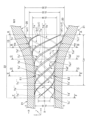
- FIG. 1 is a schematic explanatory diagram of a mouthpiece of a musical instrument according to this embodiment.
- FIG. 1 is a diagram schematically showing that a spiral groove is formed on the inner surface, and the details will be explained in FIG. 3 described later.
- FIG. 1(a) shows the front of the cup part
- FIG. 1(b) shows the cross section of the mouthpiece.
- FIGS. 1A and 1B are cross-sectional views of the mouthpiece 10 of this embodiment when it is placed horizontally, and the horizontal axis is indicated as "X".
- FIG. 1(a) is a front view of the cup, and the X axis passing through the center of the cup is indicated as "Xp".
- the mouthpiece 10 of the present embodiment has a section (also called a spiral groove forming section 22) extending from the throat portion 19 to the bottom surface of the cup inner surface 12 (hereinafter referred to as the cup inner surface bottom surface section 15). ), a spiral groove Ti (Ta, Tb, . . . , Te) is formed.
- the spiral groove Ti in FIG. 1(b) shows a cross section of a spiral groove (also referred to as a tornado groove) carved on the inner surface when viewed from one direction.
- the spiral groove Ti includes a first spiral groove Ta, a second spiral groove Tb, a third spiral groove Tc, a fourth spiral groove Td, and a third spiral groove Tc. It consists of 5 spiral grooves Te, and is mathematically similar to a Fermat spiral, a hyperbolic spiral, etc.
- the mouthpiece 10 of this embodiment has spiral grooves Ti (Ta, Tb, . . . ) extending from the throat portion 19 to the cup inner bottom surface portion 15. , Te) are cut out so that they do not overlap each other.
- the respective spiral grooves Ti (Ta, Tb, . . . , Te) are formed in a spiral shape with substantially equal intervals (details will be described later). Moreover, as shown in FIG. 1(a), when the cup is viewed from the front, the spiral groove Ti (Ta, Tb, . . . , Te) has a spiral shape.
- the other end of the first spiral groove Ta in the cup inner bottom surface portion 15 is indicated as (a1)
- the other end of the second spiral groove Tb is indicated as (b1)
- the other end of the third spiral groove Tc is indicated as (c1).
- the other end of the fourth spiral groove Td is described as (d1)
- the other end of the fifth spiral groove Te is described as (e1).
- This spiral groove Ti (Ta, Tb, . . . , Te) creates a vortex in the air flow within the mouthpiece, increasing the speed (breathing faster) and increasing the force.
- the range of skill of the player has been expanded, and it has become possible to easily reproduce sounds from the low to high range as intended. In other words, not only has the instrument become smoother, but the player's self-expression has become more reliable, which has had a positive effect on the tone and resonance.
- the mouse 10 is formed into a cylindrical shape.
- the mouthpiece 10 includes a cup portion 17, a bore portion 13, and a throat portion 19.
- the cup portion 17 (also simply referred to as a cup) has an inner surface 12 formed in a mortar shape (it may be a U cup or a V cup).
- the rear portion of the bore portion 13 is referred to as a back bore 16.
- a rim 14 is formed at a portion corresponding to the lip of the cup portion 17.
- the inner diameter of the throat portion 19 has the narrowest portion in the mouthpiece 10, and increases toward the bore portion 13.
- the mouthpiece 10 of this embodiment has a total length L1 of about 98 mm ( ⁇ 3 mm), a length of the bore portion 13 of about 43 mm, and a length of the spiral groove forming portion 22 of about 26 mm (25 mm). ⁇ 27mm is also acceptable).
- the shank 18 is shown in FIG. 1(b). Moreover, the inner wall of the mouthpiece 10 of this embodiment is written as "20", and the outer wall is written as "21". Moreover, the horizontal axis is written as "X”. Further, in FIG. 1(a), the cup center (X axis) is indicated as "Xp”. Further, in this embodiment, the section from the end of the rim 14 (the part where the lips touch) to the cup inner bottom surface 15 is referred to as a cup body 23. Moreover, in FIG. 1(b), the shank 11 is shown. That is, a cup part 17 having a cup body part 23, a shaft 11 having a minimum inner diameter part (a part E1-E1 in FIG.
- the mouthpiece of the musical instrument has a plurality of spiral grooves formed on the inner surface of the cylindrical hole.
- the length obtained by multiplying the small section by a predetermined value is The length is about five times that of the small section (cup inner bottom surface part 15), The small section is about 5 mm.
- the sections (JJ) and 2 have an inner diameter comparable to the minimum inner diameter (EE: ⁇ 16: about 8 mm).
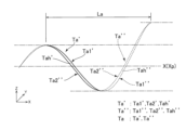
- FIG. 2 is a detailed cross-sectional view of FIG. 1(b). Components with the same reference numerals as those in FIG. 1 will not be described.
- FIG. 2 it is carved on the inner surface of the cylinder.
- the spiral grooves Ti are “Ta'", “Tb'”, “Tc'”, “Td'", “Te'” when viewed from one direction. , and those facing each other are written as “Ta'',” “Tb'', “Tc'', “Td'', and “Te''.
- These are spirally ⁇ cut in'' by a scribing tool at intervals (on the horizontal axis) of about 5 mm (3 mm to 8 mm).
- spiral grooves Ti are carved in sections of the spiral groove forming portion 22 so that each rotates one rotation (360 degrees).
- the spiral grooves Ti also referred to as notches
- the spiral grooves Ti are carved in sections of the spiral groove forming portion 22 so that each rotates one rotation (360 degrees).
- the section La (20 mm) of the first spiral groove Ta it makes one rotation (360 degrees: Ta', Ta'').
- the length L24 (on the horizontal axis) of the rim 14 is about 10 mm (8 mm to 12 mm) from the end of the rim 14 (the part where the lips touch: hereinafter referred to as the rim end).
- the length L10 of the cup body portion 23 from the rim end is approximately 29 mm (27 mm to 32 mm), and the length L14 of the cup portion 17 is approximately 39 mm (37 mm to 42 mm).
- the length L26 of the bore portion 13 is approximately 43 mm (40 mm to 45 mm).
- the length of L3 shown in FIG. 2 is about 55 mm (53 mm to 57 mm), and the length of L12 is about 34 mm (32 mm to 36 mm).
- the cup outer diameter ⁇ 1 is about 47 mm (45 mm to 49 mm)
- the cup inner diameter ⁇ 3 is about 33 mm (32 mm to 35 mm).
- the rear end outer diameter ⁇ 10 of the bore portion 16 is approximately 13 mm (11 mm to 15 mm), and the rear end inner diameter ⁇ 12 of the bore portion 16 is approximately 12 mm (10 mm to 13 mm). Furthermore, the outer diameter ⁇ 14 in FIG. 2 is approximately 7.8 mm (7.5 mm to 8.0 mm). Note that ⁇ 30 to ⁇ 34, ⁇ 16, etc. will be explained with reference to FIG.
- FIG. 3 is an enlarged view of the spiral groove forming portion 22 of the mouthpiece 10.
- FIG. 3 descriptions of components having the same reference numerals as those in the above figure will be omitted.
- FIG. 3 "Ta”, “Tb”, “Tc”, “Td”, and “Te” are indicated by dotted lines. Further, “Ta'”, “Tb'”, “Tc'”, “Td'”, and “Te'” are shown by solid lines.
- the vertical axis is "Z”
- the depth axis is "Y”
- the horizontal axis is X-axis.
- each of the spiral grooves Ti starts from one side of the inner surface near FF (at the same position).
- the distance between them is a first predetermined distance K (approximately 4 mm to 6 mm) in the Z-axis direction.
- K a first predetermined distance
- the other end ((a1), (e1), (d1), (c1), (b1)) of the spiral groove Ti is the terminal position.
- these grooves ((a1), (e1), (d1), (c1), (b1)) are attached to the cup inner surface bottom surface portion 15 of the inner surface of the cup portion 17, respectively, as shown in FIG. They are located at second predetermined intervals (approximately 5 mm to 7 mm) as shown in FIG.
- the inner diameter ⁇ 30 is about 16 mm (15 mm to 17 mm)
- the inner diameter ⁇ 34 is about 9 mm (8 mm to 11 mm)
- the inner diameter ⁇ 16 is about 8.3 mm (8 mm to 9 mm).
- the depth of "shaving" (0.1 mm to 0.2 mm) is indicated by a dotted line and written as "ma”.
- the spiral groove Ti has a shaving width (a scribing width).
- the cutting width Tah (Tah', Tah'': also referred to as scribing width) of the first spiral groove Ta is 0.4 mm to 0 between Ta1 and Ta2. It is about 8 mm.
- the inside of the cylinder of the cup lower part 24 has an inner diameter that is about half of the maximum inner diameter ( ⁇ 3: about 33 mm) of the rim 14 of the cup main body part 23, and the upper end of the cup lower part 24 ( A-A cross section: ⁇ 30: about 16 mm), and the boundary with the shaft 11 is the lower end of the cup lower portion 24 (CC cross-section: ⁇ 34: about 9 mm).
- the central portion (B-B: ⁇ 32: about 12 mm) and the upper end of the cup lower part 24 (AA cross section: ⁇ 30: about 16 mm).
- the cup portion lower part 24 is The tapered shape gradually widens from the lower end of the lower cup portion 24 (C-C cross section: approximately ⁇ 34: 9 mm) toward the upper end of the lower cup portion (BB: approximately ⁇ 32: 12 mm).
- the inner diameter gradually expands from the upper end of the lower part of the cup part (BB: about 32 mm in diameter) to the upper end of the lower part 24 of the cup part (A-A cross section: about 30 mm in diameter). It has a tapered shape.
- the plurality of spiral grooves extend from the vicinity of the lower end of the cylinder of the shaft 11 on the bore portion 13 side (FF cross section) to the upper end of the cup portion lower part 24 (AA cross section: ⁇ 30: 16 mm).
- the area up to the section (degree) is a spiral groove section, and over this spiral groove section, the intervals are made to be approximately equal to each other, and while each of the spiral groove sections advances in the longitudinal direction, 90 degrees every small section (5 mm) It is rotated with a certain degree of twist and installed around the circumference,
- the length of the spiral groove section is a predetermined times the length of the small section where the twist from one end to the other end of the spiral groove is about 450 degrees (it is rotated at least once on the inner surface of the throat portion 19, Furthermore, it extends to the bottom surface portion of the inner surface of the cup portion 17 (the inner surface bottom surface portion 15 of the cup portion 17).
- the shape of the plurality of spiral grooves from the cup main body part 23 is a spiral shape with the cylindrical hole in the center. Furthermore, the length obtained by multiplying the above-mentioned small section by a predetermined value is It is about five times as long as the small section (cup inner bottom surface part 15), and the small section is about 5 mm.
- the spiral groove forming portion 22 of the mouthpiece 10 of the present embodiment includes a first spiral groove Ta (Ta', Ta''), a second spiral groove Tb (Tb', Tb''), It consists of a third spiral groove Tc (Tc', Tc''), a fourth spiral groove Td (Td', Td''), and a fifth spiral groove Te (Te', Te'').
- a first spiral groove Ta Ta', Ta''
- Tb', Tb'' consists of a third spiral groove Tc (Tc', Tc''), a fourth spiral groove Td (Td', Td''), and a fifth spiral groove Te (Te', Te'').
- Tc', Tc'' a third spiral groove
- Td', Td'' fourth spiral groove
- Te'''' a fifth spiral groove Te
- FIG. 4 is an explanatory diagram of only the first spiral groove Ta.
- the first spiral groove Ta makes one rotation (360 degrees) in the section La. In other words, while progressing in the longitudinal direction, each small section is rotated with a twist of about 90 degrees.
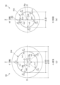
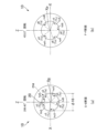
- FIG. 5(a) is an AA cross section, and is a view seen from the front of the cup with the mouthpiece 10 horizontal and the other end (a1) of the first spiral groove Ta positioned on the Z axis. (This state is also called a 0 degree rotation state).
- the angle ⁇ i (torsion angle) between the other end d1 of the spiral groove Td and the other end e1 of the fifth spiral groove Te is about 72 degrees when measured with Xp as the center.
- the outer diameter of the AA cross section is indicated as ⁇ 35.
- the grooves are shallow near the other end a1, the other end b1, the other end c1, the other end d1, and the other end e1, so although it is not shown, it can be seen that they have been "scraped" by the tool. For the sake of illustration, they are written as ha1, hb1, hc1, hd1, and he1.
- FIG. 5(b) is a BB cross section (approximately 5 mm from the AA cross section).
- the BB cross section has an inner diameter ⁇ 32 smaller than the inner diameter ⁇ 30 of the AA cross section.
- each of the first spiral grooves Ti is twisted by about 90 degrees (also referred to as 90 degree rotation) when compared with the AA cross section.
- the spiral grooves Te of the first spiral groove Ta, the second spiral groove Tb, the third spiral groove Tc, the fourth spiral groove Td, and the fifth spiral groove Te in the BB cross section are The parts are written as a2, b2, c2, d2, and e2. Also, since the "scratches" in this part are deep, they are written as ha2, hb2, hc2, hd2, and he2.
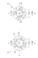
- FIG. 6(a) is a CC cross section (approximately 5 mm from the B-B cross section).
- the CC cross section has an inner diameter of ⁇ 34 (smaller than the inner diameter ⁇ 32 of the BB cross section).
- each of the fifth spiral grooves Te is twisted approximately 180 degrees (also referred to as 180 degree rotation).
- the portions of the first spiral groove Ta, second spiral groove Tb, third spiral groove Tc, fourth spiral groove Td, and fifth spiral groove Te in the CC cross section are a3, They are written as b3, c3, d3, and e3. Also, although the "scratches" in this part are shallow, they are written as ha3, hb3, hc3, hd3, and he3.
- FIG. 6(b) is the DD cross section (approximately 5 mm from the CC cross section).
- the inner diameter ⁇ 36 is smaller than the inner diameter ⁇ 34 of the CC cross section.
- the DD cross section has the first spiral groove Ta, the second spiral groove Tb, the third spiral groove Tc, the fourth spiral groove Td, and the fifth spiral groove Te. Each of these positions is twisted by approximately 270 degrees (also referred to as 270 degree rotation).
- the portions of the first spiral groove Ta, second spiral groove Tb, third spiral groove Tc, fourth spiral groove Td, and fifth spiral groove Te in the DD cross section are a4, They are written as b4, c4, d4, and e4. Moreover, the "scratches" in this part are written as ha4, hb4, hc4, hd4, and he4.
- FIG. 7(a) is the EE cross section (approximately 2.5 mm from the DD cross section).
- the EE cross section has an inner diameter of ⁇ 16 compared to the DD cross section.
- the DD cross section has the first spiral groove Ta, the second spiral groove Tb, the third spiral groove Tc, the fourth spiral groove Td, and the fifth spiral groove Te. Each of these positions is twisted by approximately 299 degrees (also referred to as a 299.43 degree rotation).
- the portions of the first spiral groove Ta, second spiral groove Tb, third spiral groove Tc, fourth spiral groove Td, and fifth spiral groove Te in the EE cross section are a5, They are written as b5, c5, d5, and e5. Moreover, the "scratches" in this part are written as ha5, hb5, hc5, hd5, and he5.
- FIG. 7(b) is the FF cross section (approximately 15 mm from the DD cross section).
- the inner diameter of the FF cross section is slightly larger than that of the E-E cross section.
- the E-E cross section shows the first spiral groove Ta, the second spiral groove Tb, the third spiral groove Tc, the fourth spiral groove Td, and the fifth spiral groove Te.
- Each of these positions is twisted by approximately 453 degrees (also referred to as 453.5 degrees rotation). That is, the spiral groove section has a twist of about 450 degrees from one end (FF section in FIG. 3) to the other end (AA section in FIG. 3).
- the portions of the first spiral groove Ta, second spiral groove Tb, third spiral groove Tc, fourth spiral groove Td, and fifth spiral groove Te in the FF cross section are a6, They are written as b6, c6, d6, and e6.
- a plurality of spiral grooves are formed from the bottom surface of the cup to the inner surface of the throat portion so as not to overlap in the longitudinal direction.
- the spiral groove Ti gives appropriate directionality (a sense of rectification) to the breath passing through the cup and throat, and the breath passes through in a swirling manner, reducing fatigue and stabilizing the bass and treble ranges. .
- the inner diameter of the throat may be small, and the bore portion may be detachable.
- the cross section of the "scratches" of the spiral groove may have any shape. It may be round or square.
- the above embodiment has been described using five spiral grooves, the number of spiral grooves may be large or small.
Landscapes
- Physics & Mathematics (AREA)
- Engineering & Computer Science (AREA)
- Acoustics & Sound (AREA)
- Multimedia (AREA)
- Toys (AREA)
Applications Claiming Priority (2)
| Application Number | Priority Date | Filing Date | Title |
|---|---|---|---|
| JP2022082873A JP7284536B1 (ja) | 2022-05-20 | 2022-05-20 | マウスピース |
| JP2022-082873 | 2022-05-20 |
Publications (1)
| Publication Number | Publication Date |
|---|---|
| WO2023223947A1 true WO2023223947A1 (ja) | 2023-11-23 |
Family
ID=86538352
Family Applications (1)
| Application Number | Title | Priority Date | Filing Date |
|---|---|---|---|
| PCT/JP2023/017835 Ceased WO2023223947A1 (ja) | 2022-05-20 | 2023-05-12 | マウスピース |
Country Status (2)
| Country | Link |
|---|---|
| JP (2) | JP7284536B1 (enExample) |
| WO (1) | WO2023223947A1 (enExample) |
Citations (4)
| Publication number | Priority date | Publication date | Assignee | Title |
|---|---|---|---|---|
| US5303628A (en) * | 1993-04-02 | 1994-04-19 | Salazar Jorge R | Mouthpiece for a clarinet and a saxophone |
| EP1596360A1 (de) * | 2004-05-10 | 2005-11-16 | Romeo Adaci | Akustische Vorrichtung, insbesondere Aerophon |
| JP2010026111A (ja) * | 2008-07-17 | 2010-02-04 | Best Brass Corp | 金管楽器のマウスピース |
| JP2012118386A (ja) * | 2010-12-02 | 2012-06-21 | Music-Craft-Japan Co Ltd | 管楽器 |
Family Cites Families (1)
| Publication number | Priority date | Publication date | Assignee | Title |
|---|---|---|---|---|
| JP3032888B2 (ja) | 1998-08-17 | 2000-04-17 | 株式会社グローバル | 金属管楽器用マウスピース |
-
2022
- 2022-05-20 JP JP2022082873A patent/JP7284536B1/ja active Active
-
2023
- 2023-05-12 WO PCT/JP2023/017835 patent/WO2023223947A1/ja not_active Ceased
- 2023-05-12 JP JP2023079074A patent/JP7674755B2/ja active Active
Patent Citations (4)
| Publication number | Priority date | Publication date | Assignee | Title |
|---|---|---|---|---|
| US5303628A (en) * | 1993-04-02 | 1994-04-19 | Salazar Jorge R | Mouthpiece for a clarinet and a saxophone |
| EP1596360A1 (de) * | 2004-05-10 | 2005-11-16 | Romeo Adaci | Akustische Vorrichtung, insbesondere Aerophon |
| JP2010026111A (ja) * | 2008-07-17 | 2010-02-04 | Best Brass Corp | 金管楽器のマウスピース |
| JP2012118386A (ja) * | 2010-12-02 | 2012-06-21 | Music-Craft-Japan Co Ltd | 管楽器 |
Also Published As
| Publication number | Publication date |
|---|---|
| JP7284536B1 (ja) | 2023-05-31 |
| JP2023171297A (ja) | 2023-12-01 |
| JP7674755B2 (ja) | 2025-05-12 |
| JP2023170818A (ja) | 2023-12-01 |
Similar Documents
| Publication | Publication Date | Title |
|---|---|---|
| JP4278112B1 (ja) | 金管楽器のマウスピース | |
| JP5960592B2 (ja) | 管楽器のためのバルブ | |
| US20060272473A1 (en) | Mouthpiece for a wind instrument | |
| WO2023223947A1 (ja) | マウスピース | |
| US5796022A (en) | Helical air path induction in wind instruments | |
| US20240194169A1 (en) | Barrel for a Woodwind Instrument | |
| US9583079B2 (en) | Silencer for wind instrument | |
| JP4440703B2 (ja) | マウスピース | |
| JP5848967B2 (ja) | 複数管オカリナ | |
| KR100451632B1 (ko) | 오카리나 악기 | |
| CN104167199B (zh) | 一种萨克斯管及其吹管、主体管 | |
| TWM540369U (zh) | 薩克斯風管體結構 | |
| CN204117579U (zh) | 一种萨克斯管及其吹管、主体管 | |
| CN207250120U (zh) | 萨克斯管吹嘴的束圈 | |
| JP6434887B2 (ja) | 木管楽器 | |
| KR102642453B1 (ko) | 마감부가 포함된 톤홀구조체가 장착된 관악기 | |
| KR102680320B1 (ko) | 색소폰용 마우스피스 키트 | |
| CN220340894U (zh) | 一种长号的吹嘴 | |
| WO2006027819A1 (ja) | 唄口、接続管及びそれを有する管楽器 | |
| CN218676448U (zh) | 一种调节竹节打孔的箫头组件 | |
| US20250087195A1 (en) | Musical Instrument | |
| JP3105230U (ja) | 金管楽器用マウスピース | |
| JPH0547994U (ja) | 管楽器用マウスピース | |
| CN211181620U (zh) | 一种带有倒圆角的平行吹孔竹笛 | |
| JP2008152015A (ja) | 金管楽器用マウスピース |
Legal Events
| Date | Code | Title | Description |
|---|---|---|---|
| 121 | Ep: the epo has been informed by wipo that ep was designated in this application |
Ref document number: 23807550 Country of ref document: EP Kind code of ref document: A1 |
|
| NENP | Non-entry into the national phase |
Ref country code: DE |
|
| 122 | Ep: pct application non-entry in european phase |
Ref document number: 23807550 Country of ref document: EP Kind code of ref document: A1 |