WO2023218693A1 - 機能ルーフ及びその製造方法 - Google Patents
機能ルーフ及びその製造方法 Download PDFInfo
- Publication number
- WO2023218693A1 WO2023218693A1 PCT/JP2022/047955 JP2022047955W WO2023218693A1 WO 2023218693 A1 WO2023218693 A1 WO 2023218693A1 JP 2022047955 W JP2022047955 W JP 2022047955W WO 2023218693 A1 WO2023218693 A1 WO 2023218693A1
- Authority
- WO
- WIPO (PCT)
- Prior art keywords
- layer
- protection material
- sealing layer
- barrier sheet
- barrier
- Prior art date
- Legal status (The legal status is an assumption and is not a legal conclusion. Google has not performed a legal analysis and makes no representation as to the accuracy of the status listed.)
- Ceased
Links
Images




Classifications
-
- B—PERFORMING OPERATIONS; TRANSPORTING
- B62—LAND VEHICLES FOR TRAVELLING OTHERWISE THAN ON RAILS
- B62D—MOTOR VEHICLES; TRAILERS
- B62D25/00—Superstructure or monocoque structure sub-units; Parts or details thereof not otherwise provided for
- B62D25/06—Fixed roofs
-
- B—PERFORMING OPERATIONS; TRANSPORTING
- B32—LAYERED PRODUCTS
- B32B—LAYERED PRODUCTS, i.e. PRODUCTS BUILT-UP OF STRATA OF FLAT OR NON-FLAT, e.g. CELLULAR OR HONEYCOMB, FORM
- B32B27/00—Layered products comprising a layer of synthetic resin
- B32B27/06—Layered products comprising a layer of synthetic resin as the main or only constituent of a layer, which is next to another layer of the same or of a different material
- B32B27/08—Layered products comprising a layer of synthetic resin as the main or only constituent of a layer, which is next to another layer of the same or of a different material of synthetic resin
-
- B—PERFORMING OPERATIONS; TRANSPORTING
- B32—LAYERED PRODUCTS
- B32B—LAYERED PRODUCTS, i.e. PRODUCTS BUILT-UP OF STRATA OF FLAT OR NON-FLAT, e.g. CELLULAR OR HONEYCOMB, FORM
- B32B3/00—Layered products comprising a layer with external or internal discontinuities or unevennesses, or a layer of non-planar shape; Layered products comprising a layer having particular features of form
- B32B3/02—Layered products comprising a layer with external or internal discontinuities or unevennesses, or a layer of non-planar shape; Layered products comprising a layer having particular features of form characterised by features of form at particular places, e.g. in edge regions
- B32B3/04—Layered products comprising a layer with external or internal discontinuities or unevennesses, or a layer of non-planar shape; Layered products comprising a layer having particular features of form characterised by features of form at particular places, e.g. in edge regions characterised by at least one layer folded at the edge, e.g. over another layer ; characterised by at least one layer enveloping or enclosing a material
-
- B—PERFORMING OPERATIONS; TRANSPORTING
- B32—LAYERED PRODUCTS
- B32B—LAYERED PRODUCTS, i.e. PRODUCTS BUILT-UP OF STRATA OF FLAT OR NON-FLAT, e.g. CELLULAR OR HONEYCOMB, FORM
- B32B3/00—Layered products comprising a layer with external or internal discontinuities or unevennesses, or a layer of non-planar shape; Layered products comprising a layer having particular features of form
- B32B3/26—Layered products comprising a layer with external or internal discontinuities or unevennesses, or a layer of non-planar shape; Layered products comprising a layer having particular features of form characterised by a particular shape of the outline of the cross-section of a continuous layer; characterised by a layer with cavities or internal voids ; characterised by an apertured layer
- B32B3/30—Layered products comprising a layer with external or internal discontinuities or unevennesses, or a layer of non-planar shape; Layered products comprising a layer having particular features of form characterised by a particular shape of the outline of the cross-section of a continuous layer; characterised by a layer with cavities or internal voids ; characterised by an apertured layer characterised by a layer formed with recesses or projections, e.g. hollows, grooves, protuberances, ribs
-
- B—PERFORMING OPERATIONS; TRANSPORTING
- B32—LAYERED PRODUCTS
- B32B—LAYERED PRODUCTS, i.e. PRODUCTS BUILT-UP OF STRATA OF FLAT OR NON-FLAT, e.g. CELLULAR OR HONEYCOMB, FORM
- B32B37/00—Methods or apparatus for laminating, e.g. by curing or by ultrasonic bonding
- B32B37/06—Methods or apparatus for laminating, e.g. by curing or by ultrasonic bonding characterised by the heating method
-
- B—PERFORMING OPERATIONS; TRANSPORTING
- B32—LAYERED PRODUCTS
- B32B—LAYERED PRODUCTS, i.e. PRODUCTS BUILT-UP OF STRATA OF FLAT OR NON-FLAT, e.g. CELLULAR OR HONEYCOMB, FORM
- B32B37/00—Methods or apparatus for laminating, e.g. by curing or by ultrasonic bonding
- B32B37/10—Methods or apparatus for laminating, e.g. by curing or by ultrasonic bonding characterised by the pressing technique, e.g. using action of vacuum or fluid pressure
-
- B—PERFORMING OPERATIONS; TRANSPORTING
- B32—LAYERED PRODUCTS
- B32B—LAYERED PRODUCTS, i.e. PRODUCTS BUILT-UP OF STRATA OF FLAT OR NON-FLAT, e.g. CELLULAR OR HONEYCOMB, FORM
- B32B37/00—Methods or apparatus for laminating, e.g. by curing or by ultrasonic bonding
- B32B37/14—Methods or apparatus for laminating, e.g. by curing or by ultrasonic bonding characterised by the properties of the layers
- B32B37/16—Methods or apparatus for laminating, e.g. by curing or by ultrasonic bonding characterised by the properties of the layers with all layers existing as coherent layers before laminating
- B32B37/18—Methods or apparatus for laminating, e.g. by curing or by ultrasonic bonding characterised by the properties of the layers with all layers existing as coherent layers before laminating involving the assembly of discrete sheets or panels only
- B32B37/182—Methods or apparatus for laminating, e.g. by curing or by ultrasonic bonding characterised by the properties of the layers with all layers existing as coherent layers before laminating involving the assembly of discrete sheets or panels only one or more of the layers being plastic
-
- B—PERFORMING OPERATIONS; TRANSPORTING
- B32—LAYERED PRODUCTS
- B32B—LAYERED PRODUCTS, i.e. PRODUCTS BUILT-UP OF STRATA OF FLAT OR NON-FLAT, e.g. CELLULAR OR HONEYCOMB, FORM
- B32B37/00—Methods or apparatus for laminating, e.g. by curing or by ultrasonic bonding
- B32B37/14—Methods or apparatus for laminating, e.g. by curing or by ultrasonic bonding characterised by the properties of the layers
- B32B37/24—Methods or apparatus for laminating, e.g. by curing or by ultrasonic bonding characterised by the properties of the layers with at least one layer not being coherent before laminating, e.g. made up from granular material sprinkled onto a substrate
-
- B—PERFORMING OPERATIONS; TRANSPORTING
- B32—LAYERED PRODUCTS
- B32B—LAYERED PRODUCTS, i.e. PRODUCTS BUILT-UP OF STRATA OF FLAT OR NON-FLAT, e.g. CELLULAR OR HONEYCOMB, FORM
- B32B7/00—Layered products characterised by the relation between layers; Layered products characterised by the relative orientation of features between layers, or by the relative values of a measurable parameter between layers, i.e. products comprising layers having different physical, chemical or physicochemical properties; Layered products characterised by the interconnection of layers
- B32B7/02—Physical, chemical or physicochemical properties
- B32B7/022—Mechanical properties
-
- H—ELECTRICITY
- H02—GENERATION; CONVERSION OR DISTRIBUTION OF ELECTRIC POWER
- H02S—GENERATION OF ELECTRIC POWER BY CONVERSION OF INFRARED RADIATION, VISIBLE LIGHT OR ULTRAVIOLET LIGHT, e.g. USING PHOTOVOLTAIC [PV] MODULES
- H02S20/00—Supporting structures for PV modules
- H02S20/30—Supporting structures being movable or adjustable, e.g. for angle adjustment
-
- H—ELECTRICITY
- H10—SEMICONDUCTOR DEVICES; ELECTRIC SOLID-STATE DEVICES NOT OTHERWISE PROVIDED FOR
- H10F—INORGANIC SEMICONDUCTOR DEVICES SENSITIVE TO INFRARED RADIATION, LIGHT, ELECTROMAGNETIC RADIATION OF SHORTER WAVELENGTH OR CORPUSCULAR RADIATION
- H10F19/00—Integrated devices, or assemblies of multiple devices, comprising at least one photovoltaic cell covered by group H10F10/00, e.g. photovoltaic modules
- H10F19/80—Encapsulations or containers for integrated devices, or assemblies of multiple devices, having photovoltaic cells
-
- B—PERFORMING OPERATIONS; TRANSPORTING
- B32—LAYERED PRODUCTS
- B32B—LAYERED PRODUCTS, i.e. PRODUCTS BUILT-UP OF STRATA OF FLAT OR NON-FLAT, e.g. CELLULAR OR HONEYCOMB, FORM
- B32B37/00—Methods or apparatus for laminating, e.g. by curing or by ultrasonic bonding
- B32B37/14—Methods or apparatus for laminating, e.g. by curing or by ultrasonic bonding characterised by the properties of the layers
- B32B37/24—Methods or apparatus for laminating, e.g. by curing or by ultrasonic bonding characterised by the properties of the layers with at least one layer not being coherent before laminating, e.g. made up from granular material sprinkled onto a substrate
- B32B2037/243—Coating
-
- B—PERFORMING OPERATIONS; TRANSPORTING
- B32—LAYERED PRODUCTS
- B32B—LAYERED PRODUCTS, i.e. PRODUCTS BUILT-UP OF STRATA OF FLAT OR NON-FLAT, e.g. CELLULAR OR HONEYCOMB, FORM
- B32B2255/00—Coating on the layer surface
- B32B2255/10—Coating on the layer surface on synthetic resin layer or on natural or synthetic rubber layer
-
- B—PERFORMING OPERATIONS; TRANSPORTING
- B32—LAYERED PRODUCTS
- B32B—LAYERED PRODUCTS, i.e. PRODUCTS BUILT-UP OF STRATA OF FLAT OR NON-FLAT, e.g. CELLULAR OR HONEYCOMB, FORM
- B32B2307/00—Properties of the layers or laminate
- B32B2307/40—Properties of the layers or laminate having particular optical properties
- B32B2307/412—Transparent
-
- B—PERFORMING OPERATIONS; TRANSPORTING
- B32—LAYERED PRODUCTS
- B32B—LAYERED PRODUCTS, i.e. PRODUCTS BUILT-UP OF STRATA OF FLAT OR NON-FLAT, e.g. CELLULAR OR HONEYCOMB, FORM
- B32B2307/00—Properties of the layers or laminate
- B32B2307/50—Properties of the layers or laminate having particular mechanical properties
- B32B2307/546—Flexural strength; Flexion stiffness
-
- B—PERFORMING OPERATIONS; TRANSPORTING
- B32—LAYERED PRODUCTS
- B32B—LAYERED PRODUCTS, i.e. PRODUCTS BUILT-UP OF STRATA OF FLAT OR NON-FLAT, e.g. CELLULAR OR HONEYCOMB, FORM
- B32B2605/00—Vehicles
-
- Y—GENERAL TAGGING OF NEW TECHNOLOGICAL DEVELOPMENTS; GENERAL TAGGING OF CROSS-SECTIONAL TECHNOLOGIES SPANNING OVER SEVERAL SECTIONS OF THE IPC; TECHNICAL SUBJECTS COVERED BY FORMER USPC CROSS-REFERENCE ART COLLECTIONS [XRACs] AND DIGESTS
- Y02—TECHNOLOGIES OR APPLICATIONS FOR MITIGATION OR ADAPTATION AGAINST CLIMATE CHANGE
- Y02B—CLIMATE CHANGE MITIGATION TECHNOLOGIES RELATED TO BUILDINGS, e.g. HOUSING, HOUSE APPLIANCES OR RELATED END-USER APPLICATIONS
- Y02B10/00—Integration of renewable energy sources in buildings
- Y02B10/10—Photovoltaic [PV]
-
- Y—GENERAL TAGGING OF NEW TECHNOLOGICAL DEVELOPMENTS; GENERAL TAGGING OF CROSS-SECTIONAL TECHNOLOGIES SPANNING OVER SEVERAL SECTIONS OF THE IPC; TECHNICAL SUBJECTS COVERED BY FORMER USPC CROSS-REFERENCE ART COLLECTIONS [XRACs] AND DIGESTS
- Y02—TECHNOLOGIES OR APPLICATIONS FOR MITIGATION OR ADAPTATION AGAINST CLIMATE CHANGE
- Y02E—REDUCTION OF GREENHOUSE GAS [GHG] EMISSIONS, RELATED TO ENERGY GENERATION, TRANSMISSION OR DISTRIBUTION
- Y02E10/00—Energy generation through renewable energy sources
- Y02E10/50—Photovoltaic [PV] energy
Definitions
- This disclosure relates to a functional roof and a method of manufacturing the same.
- a solar cell includes a back sheet with a cylindrical structure and a first gas barrier sheet and a second gas barrier sheet provided along the outer periphery of a sealing material.
- An object of the present invention is to provide a functional roof that can suppress the generation of bubbles in the sealing layer and a method for manufacturing the same.
- a functional roof includes a functional layer having a predetermined function, a sealing layer that seals the functional layer, and connects a front surface, a back surface, and the front surface and the back surface. and a surrounding end face annularly surrounding the periphery of the functional layer; a surface protection material made of a resin having optical transparency and protecting the surface of the sealing layer; and the sealing layer.
- a front barrier sheet comprising a back surface protection material that protects the back surface of the layer, and a barrier layer that covers the sealing layer, the barrier layer being disposed between the sealing layer and the surface protection material.
- the front side barrier sheet including a surface coating portion that covers the entire surface of the sealing layer
- the backside barrier sheet includes a backside covering portion that covers the entire backside of the sealing layer
- the frontside barrier sheet has a front side that overhangs an edge of the frontside coating portion and is spaced from the surface protection material.
- the front side overhang part is connected to the back side barrier sheet while covering the surrounding end surface, or the back side barrier sheet overhangs from the edge of the back side covering part. and a back side protruding portion spaced apart from the back side protective material, and the back side extending portion is connected to the front side barrier sheet in a state of covering the surrounding end surface.
- a method for manufacturing a functional roof includes a functional layer having a predetermined function, a sealing layer that seals the functional layer, and a resin having light transmittance.
- a surface protection material that protects the surface of the layer, a back surface protection material that protects the back surface of the sealing layer, and a barrier layer that covers the sealing layer, and the barrier layer includes the sealing layer and the sealing layer.
- a method for producing a functional roof comprising: a front barrier sheet disposed between the surface protection material; and a back barrier sheet disposed between the sealing layer and the back protection material, the method comprising: a protective material, the front barrier sheet, a plurality of sealing layer forming materials constituting the sealing layer, the functional layer disposed within the plurality of sealing layer forming materials, and the back barrier sheet. , a laminate forming step of forming a laminate by laminating the back surface protective material, and softening the functional layer by heating the laminate to soften the plurality of sealing layer forming materials. an unifying step of forming the sealing layer for sealing and forming the barrier layer covering the sealing layer by connecting the front side barrier sheet and the back side barrier sheet to each other; and the unifying step.
- the surface protection material, the sealing layer, the barrier layer, and the back surface protection material are shaped so that they curve convexly toward one side in the lamination direction.
- FIG. 2 is a plan view schematically showing a functional roof in an embodiment of the present disclosure. 2 is a sectional view taken along line II-II in FIG. 1.
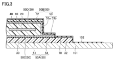
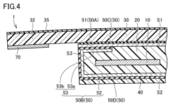
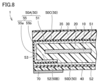
- FIG. FIG. 2 is a cross-sectional view schematically showing a method for manufacturing a functional roof. It is a figure which shows schematically the modification of a functional roof. It is a figure which shows schematically the modification of a functional roof. It is a figure which shows schematically the modification of a functional roof. It is a figure which shows schematically the modification of a functional roof. It is a figure which shows schematically the modification of a functional roof. It is a figure which shows schematically the modification of a functional roof. It is a figure which shows schematically the modification of a functional roof.
- FIG. 1 is a diagram schematically showing a functional roof in an embodiment of the present disclosure.
- FIG. 2 is a sectional view taken along line II-II in FIG. 1. This functional roof 1 is preferably used in a vehicle.
- the functional roof 1 includes a functional layer 10, a sealing layer 20, a surface protection material 30, a hard coat layer 35, a back surface protection material 40, a barrier layer 50, A shielding section 70 is provided.
- the functional layer 10 has a predetermined function.
- the predetermined functions include a power generation function, a light control function, and a display function.
- the predetermined function is a power generation function
- the functional layer 10 is composed of a solar power generation panel.
- the predetermined function is a light control function
- the functional layer 10 is composed of a light control film (a film whose light transmittance can be adjusted by applying a voltage).
- the predetermined function is a display function
- the functional layer 10 is constituted by a display device (LED, organic EL, liquid crystal, etc.).
- the functional layer 10 is generally formed into a flat plate shape.
- the functional layer 10 has a first main surface 10a, a second main surface 10b, and an end surface 10c.
- the first main surface 10a is a surface formed on one side (upper side in FIG. 2) of the functional layer 10 in the thickness direction (vertical direction in FIG. 2).
- the first main surface 10a is formed substantially flat.
- the second main surface 10b is a surface formed on the other side of the functional layer 10 in the thickness direction.
- the second main surface 10b is formed substantially flat.
- the end surface 10c has a shape that connects the first main surface 10a and the second main surface 10b and is connected in an annular shape.
- the sealing layer 20 seals the functional layer 10. More specifically, the sealing layer 20 seals the entire first main surface 10a, the second main surface 10b, and the end surface 10c of the functional layer 10.
- the sealing layer 20 is made of a light-transmitting resin.
- the sealing layer 20 is made of, for example, ethylene vinyl acetate (EVA), polyolefin, silicone, or ionomer.
- EVA ethylene vinyl acetate
- the sealing layer 20 is formed by heating the laminated sheets (sealing layer forming material) made of the resin described above.
- the sealing layer 20 has a front surface S1, a back surface S2, and a surrounding end surface S3.
- the surface S1 is provided on one side of the functional layer 10 in the thickness direction of the functional layer 10, and is constituted by the main surface on one side of the sealing layer 20.
- the back surface S2 is provided on the other side of the functional layer 10 in the thickness direction of the functional layer 10, and is constituted by the main surface on the other side of the sealing layer 20.
- the surrounding end surface S3 connects the front surface S1 and the back surface S2 and surrounds the functional layer 10 in an annular shape.
- the surface protection material 30 protects the surface S1 of the sealing layer 20.
- the surface protection material 30 is provided on one side (the upper side in FIG. 2) of the sealing layer 20 via a front barrier sheet 50A and a front adhesive layer 50C, which will be described later.
- the surface protection material 30 is made of a light-transmitting resin.
- the surface protection material 30 is made of, for example, polycarbonate (PC), polymethyl methacrylate (PMMA), polyethylene terephthalate (PET), or polypropylene (PP).
- the hard coat layer 35 is provided on the surface of the surface protection material 30.
- the hard coat layer 35 is made of a material with higher hardness than the material constituting the surface protection material 30 and covers the surface of the surface protection material 30.
- the hard coat layer 35 is made of a light-transmitting material.
- the back surface protection material 40 protects the back surface S2 of the sealing layer 20.
- the back surface protection material 40 is provided on the other side (lower side in FIG. 2) with respect to the sealing layer 20 via a back side barrier sheet 50B and a back side adhesive layer 50D, which will be described later.
- the outer shape of the back surface protection material 40 in a plan view is formed to be approximately the same as the outer shape of the back surface S2 of the sealing layer 20 in a plan view.
- the thickness of the back surface protection material 40 is smaller than the thickness of the surface protection material 30.
- the bending rigidity of the front surface protection material 30 is higher than that of the back surface protection material 40.
- the back surface protection material 40 is formed of a material having light transmittance.
- the back protection material 40 is made of, for example, polycarbonate (PC), ABS resin, or a mixture thereof.
- the barrier layer 50 covers the sealing layer 20.
- the barrier layer 50 is made of a material (such as a resin material) that prevents gas and water vapor from passing through.
- the barrier layer 50 is formed in a film shape (thin film shape). As shown in FIG. 2, the barrier layer 50 includes a front barrier sheet 50A, a back barrier sheet 50B, a front adhesive layer 50C, and a back adhesive layer 50D.
- the front barrier sheet 50A is arranged between the sealing layer 20 and the surface protection material 30.
- the front barrier sheet 50A is made of a light-transmitting material.
- the front barrier sheet 50A includes a surface covering portion 51 and a front extension portion 54.
- the surface covering portion 51 covers the entire surface S1 of the sealing layer 20.
- the outer shape of the surface covering portion 51 in a plan view substantially corresponds to the outer shape of the surface S1 of the sealing layer 20 in a plan view.
- the front side extension part 54 extends from the edge of the surface covering part 51 and is connected to the surface protection material 30. That is, the front side extension part 54 is formed at a position that does not overlap with the sealing layer 20 in the thickness direction of the functional roof 1 (vertical direction in FIG. 2).
- the front adhesive layer 50C is provided over the entire surface of the front barrier sheet 50A, and adheres the front barrier sheet 50A to the surface protection material 30.
- the front adhesive layer 50C is made of a light-transmitting material (synthetic resin, etc.).
- the outer shape of the front adhesive layer 50C is substantially the same as the outer shape of the front barrier sheet 50A.
- the back barrier sheet 50B is arranged between the sealing layer 20 and the back protection material 40.
- the back side barrier sheet 50B is made of a light-transmitting material.
- the back side barrier sheet 50B has a back side covering portion 52 and a back side projecting portion 53.
- the back surface covering portion 52 covers the entire back surface S2 of the sealing layer 20.
- the outer shape of the back surface covering portion 52 in a plan view substantially corresponds to the outer shape of the back surface S2 of the sealing layer 20 in a plan view.
- the backside overhanging portion 53 overhangs from the edge of the backside covering portion 52.
- the back side projecting portion 53 is spaced apart from the back side protection material 40.
- the back side protruding portion 53 is connected to the front side barrier sheet 50A while covering the surrounding end surface S3 of the sealing layer 20.
- the backside projecting portion 53 has an end surface covering portion 53a and a backside sheet end portion 53b.
- the end surface covering portion 53a is connected to the edge of the back surface covering portion 52 and covers the surrounding end surface S3 of the sealing layer 20. A space may be formed between the end face covering portion 53a and the surrounding end face S3.
- the back sheet end portion 53b is connected to the front barrier sheet 50A. In this embodiment, the back sheet end portion 53b is connected to the front side extension portion 54.
- the backside adhesive layer 50D is provided over the entire backside of the backside barrier sheet 50B, and adheres the backside barrier sheet 50B to the backside protection material 40.
- the back side adhesive layer 50D is made of a light-transmitting material (synthetic resin, etc.).
- the outer shape of the back side adhesive layer 50D is substantially the same as the outer shape of the back side barrier sheet 50B.
- the shielding part 70 is made of a black material (ceramic, etc.).
- the shielding part 70 is provided on the back surface of the surface protection material 30. More specifically, the surface protection material 30 has a flange portion 32 that protrudes outward from a portion overlapping with the sealing layer 20 in the thickness direction, and the shielding portion 70 is provided on the back surface of the flange portion 32. There is.
- This manufacturing method includes a laminate forming step, an integrating step, and a hot pressing step.
- the back barrier sheet 50B, and the back protection material 40 are stacked to form a laminate. More specifically, in the laminate forming step, the surface protection material 30 provided with the hard coat layer 35, the front adhesive layer 50C, the front barrier sheet 50A, and the plurality of sealing layer forming materials and the functional layer 10.
- a laminate is formed by laminating the back barrier sheet 50B, the back adhesive layer 50D, and the back protection material 40.
- the surface protection material 30 provided with the hard coat layer 35, the front adhesive layer 50C, and the front barrier sheet 50A are heated to be integrated in advance. may have been done.
- the back protection material 40 and the back covering portion 52 of the back barrier sheet 50B may be heated to be integrated in advance.
- the laminate is heated to soften the plurality of sealing layer forming materials, thereby forming the sealing layer 20 that seals the functional layer 10, and also forming the front barrier sheet 50A and the back barrier sheet.
- a barrier layer 50 covering the sealing layer 20 is formed by connecting the sheets 50B to each other.
- a laminate is placed on a heated plate-like member 101, and the laminate is covered with a sheet 102 made of rubber.
- the laminate is integrated by evacuating the space between the member 101 and the sheet 102.
- the front side extension part 54 of the front side barrier sheet 50A and the back side sheet end part 53b of the back side barrier sheet 50B are connected to each other.
- an end face covering portion 53a that covers the surrounding end face S3 of the sealing layer 20 is formed.
- the hot press step is performed after the integration step.
- the hard coat layer 35, the surface protection material 30, the sealing layer 20, the barrier layer 50, and the back protection material 40 are stacked toward one side in the lamination direction, more specifically, from the back protection material 40 to the surface.
- the hard coat layer 35, the surface protection material 30, the sealing layer 20, the barrier layer 50, and the back surface protection material 40 are pressed while being heated so as to form a curved shape convex toward the protection material 30.
- the barrier layer 50 has the front surface coating portion 51, the back surface coating portion 52, and the end surface coating portion 53a, gas and water vapor to the sealing layer 20 The generation of bubbles in the sealing layer 20 due to the entry of air bubbles is suppressed.
- the backside protruding portion 53 is spaced apart from the backside protection material 40, the external shape of the backside protection material 40 in plan view is reduced to the same size as the outside shape of the backside S2 of the sealing layer 20 in planar view. It becomes possible to do so.
- the back sheet end portion 53b may be arranged between the surface covering portion 51 and the sealing layer 20.
- the front side extension part 54 may be omitted, and the front side barrier sheet 50A may be comprised only of the surface coating part 51.
- the front barrier sheet 50A and the back barrier sheet 50B are connected to each other via the back adhesive layer 50D, airtightness is improved.
- the backside overhanging portion 53 may be omitted from the backside barrier sheet 50B, and the frontside barrier sheet 50A may have a frontside overhanging portion 55 in place of the frontside extension portion 54.
- the front side overhang portion 55 overhangs from the edge of the surface covering portion 51 and is spaced apart from the surface protection material 30.
- the front side projecting portion 55 is connected to the back side barrier sheet 50B while covering the surrounding end surface S3.
- the front side overhang portion 55 has an end surface covering portion 55a and a front side sheet end portion 55b.
- the end face covering part 55a is connected to the edge of the surface covering part 51 and covers the surrounding end face S3 of the sealing layer 20. A space may be formed between the end face covering portion 55a and the surrounding end face S3.
- the front sheet end 55b is connected to the back barrier sheet 50B.
- the back protection material 40 has a flange portion 42 that extends outward from a portion overlapping with the sealing layer 20 in the thickness direction, and the back barrier sheet 50B extends from the edge of the back covering portion 52. It has a back side extension 56 connected to the cage flange 42, and the front sheet end 55b is connected to the back side extension 56.
- the front sheet end portion 55b may be arranged between the back surface covering portion 52 and the sealing layer 20.
- the back side extension part 56 may be omitted, and the back side barrier sheet 50B may be comprised only of the back side covering part 52.
- the front barrier sheet 50A and the back barrier sheet 50B are connected to each other via the front adhesive layer 50C, airtightness is improved as in the first modification.
- (Aspect 1) a functional layer having a predetermined function;
- a sealing layer that seals the functional layer, the sealing layer having a front surface, a back surface, and a surrounding end surface that connects the front surface and the back surface and surrounds the functional layer in an annular shape.
- the barrier layer is a front barrier sheet disposed between the sealing layer and the surface protection material; a backside barrier sheet disposed between the sealing layer and the backside protection material,
- the front barrier sheet includes a surface covering portion that covers the entire surface of the sealing layer,
- the backside barrier sheet includes a backside coating portion that covers the entire backside of the sealing layer,
- the front side barrier sheet has a front side overhang that overhangs an edge of the surface covering part and is spaced apart from the surface protection material, and the front side overhang has a front side overhang that covers the surrounding end surface and is attached to the back side barrier sheet.
- the backside barrier sheet is connected to the sheet, or the backside barrier sheet has a backside overhang that overhangs an edge of the backside covering and is spaced apart from the backside protection material, and the backside overhang is connected to the surrounding area.
- a functional roof connected to the front barrier sheet with its end surface covered.
- the barrier layer has a surface coating part, a back coating part, and a front side overhang part or a back side overhang part, sealing caused by gas or water vapor entering the sealing layer can be prevented. Generation of bubbles in the stop layer is suppressed.
- the back side barrier sheet has the back side overhang,
- the backside protruding portion is an end face covering part that covers the surrounding end face; and a back sheet end connected to the front barrier sheet.
- the front barrier sheet has a front side extension part extending from the edge of the surface covering part and connected to the surface protection material, A functional roof according to aspect 2, wherein the back sheet end is connected to the front extension.
- the front barrier sheet has the front side overhang,
- the front side projecting portion is an end face covering part that covers the surrounding end face;
- a functional roof according to aspect 1, comprising: a front sheet end connected to the back barrier sheet.
- the back side barrier sheet has a back side extension part extending from the edge of the back side covering part and connected to the back side protective material, 6.
- the surface protection material, the surface coating portion, the sealing layer, the back surface coating portion, and the back surface protection material have a shape that is curved so as to be convex in a direction from the back surface protection material toward the surface protection material.
- the functional roof according to any one of aspects 1 to 7.
- a functional layer having a predetermined function a sealing layer for sealing the functional layer; a surface protection material made of a light-transmitting resin and protecting the surface of the sealing layer; and a back surface of the sealing layer. and a barrier layer that covers the sealing layer, and the barrier layer includes a front barrier sheet disposed between the sealing layer and the surface protection material, and a barrier layer that covers the sealing layer.
- a method for manufacturing a functional roof comprising: a backside barrier sheet disposed between a stop layer and the backside protection material; The surface protection material, the front barrier sheet, a plurality of sealing layer forming materials constituting the sealing layer, the functional layer disposed within the plurality of sealing layer forming materials, and the back side barrier.
- a laminate forming step of forming a laminate by laminating the sheet and the back surface protective material By heating the laminate, the plurality of sealing layer forming materials are softened to form the sealing layer that seals the functional layer, and the front barrier sheet and the back barrier sheet are an integrating step of forming the barrier layer covering the sealing layer by connecting to each other; After the integration step, the surface protection material is shaped so that the surface protection material, the sealing layer, the barrier layer, and the back protection material have a curved shape convex toward one side in the lamination direction.
- a method for manufacturing a functional roof comprising: a hot pressing step of heating and pressing the sealing layer, the barrier layer, and the back surface protection material.
- the laminate is made of a material with higher hardness than the material constituting the surface protection material and further includes a hard coat layer covering the surface of the surface protection material,
Landscapes
- Engineering & Computer Science (AREA)
- Mechanical Engineering (AREA)
- Chemical & Material Sciences (AREA)
- Combustion & Propulsion (AREA)
- Transportation (AREA)
- Physics & Mathematics (AREA)
- Fluid Mechanics (AREA)
- Laminated Bodies (AREA)
- Body Structure For Vehicles (AREA)
- Photovoltaic Devices (AREA)
Abstract
Description
(第1変形例)
図4に示されるように、裏側シート端部53bは、表面被覆部51と封止層20との間に配置されていてもよい。この場合、表側延長部54が省略され、表側バリアシート50Aが表面被覆部51のみで構成されてもよい。この例では、表側バリアシート50Aと裏側バリアシート50Bとが裏側接着層50Dを介して互いに接続されるため、気密性が向上する。
図5に示されるように、裏側シート端部53bが表面被覆部51と封止層20との間に配置されており、かつ、遮蔽部70が裏面保護材40の裏面に設けられていてもよい。この例においても、表側延長部54が省略され、表側バリアシート50Aが表面被覆部51のみで構成されてもよい。また、この例では、表面保護材30のフランジ部32は、省略されていてもよい。
図6に示されるように、裏側バリアシート50Bから裏側張出部53が省略され、表側バリアシート50Aは、表側延長部54に代えて表側張出部55を有していてもよい。表側張出部55は、表面被覆部51の縁部から張り出しておりかつ表面保護材30から離間している。表側張出部55は、包囲端面S3を被覆した状態で裏側バリアシート50Bに接続されている。表側張出部55は、端面被覆部55aと、表側シート端部55bと、を有している。
図7に示されるように、表側シート端部55bは、裏面被覆部52と封止層20との間に配置されていてもよい。この場合、裏側延長部56が省略され、裏側バリアシート50Bが裏面被覆部52のみで構成されてもよい。この例では、表側バリアシート50Aと裏側バリアシート50Bとが表側接着層50Cを介して互いに接続されるため、第1変形例と同様に気密性が向上する。
図8に示されるように、表側シート端部55bが裏面被覆部52と封止層20との間に配置されており、かつ、遮蔽部70が裏面保護材40の裏面に設けられていてもよい。この場合においても、裏側延長部56が省略され、裏側バリアシート50Bが裏面被覆部52のみで構成されてもよい。また、この例では、表面保護材30のフランジ部32は、省略されていてもよい。
上述した例示的な実施形態は、以下の態様の具体例であることが当業者により理解される。
所定の機能を有する機能層と、
前記機能層を封止する封止層であって、表面と、裏面と、前記表面と前記裏面とを連結するとともに前記機能層の周囲を環状に包囲する包囲端面と、を有する前記封止層と、
光透過性を有する樹脂からなり、前記封止層の前記表面を保護する表面保護材と、
前記封止層の前記裏面を保護する裏面保護材と、
前記封止層を被覆するバリア層と、を備え、
前記バリア層は、
前記封止層と前記表面保護材との間に配置された表側バリアシートと、
前記封止層と前記裏面保護材との間に配置された裏側バリアシートと、を含み、
前記表側バリアシートは、前記封止層の前記表面の全域を被覆する表面被覆部を含み、
前記裏側バリアシートは、前記封止層の前記裏面の全域を被覆する裏面被覆部を含み、
前記表側バリアシートは、前記表面被覆部の縁部から張り出しておりかつ前記表面保護材から離間した表側張出部を有し、前記表側張出部は前記包囲端面を被覆した状態で前記裏側バリアシートに接続されている、あるいは、前記裏側バリアシートは、前記裏面被覆部の縁部から張り出しておりかつ前記裏面保護材から離間した裏側張出部を有し、前記裏側張出部は前記包囲端面を被覆した状態で前記表側バリアシートに接続されている、機能ルーフ。
前記裏側バリアシートは、前記裏側張出部を有し、
前記裏側張出部は、
前記包囲端面を被覆する端面被覆部と、
前記表側バリアシートに接続された裏側シート端部と、を有する、態様1に記載の機能ルーフ。
前記表側バリアシートは、前記表面被覆部の前記縁部から延長されており前記表面保護材に接続された表側延長部を有し、
前記裏側シート端部は、前記表側延長部に接続されている、態様2に記載の機能ルーフ。
前記裏側シート端部は、前記表面被覆部と前記封止層との間に配置されている、態様2に記載の機能ルーフ。
前記表側バリアシートは、前記表側張出部を有し、
前記表側張出部は、
前記包囲端面を被覆する端面被覆部と、
前記裏側バリアシートに接続された表側シート端部と、を有する、態様1に記載の機能ルーフ。
前記裏側バリアシートは、前記裏面被覆部の前記縁部から延長されており前記裏面保護材に接続された裏側延長部を有し、
前記表側シート端部は、前記裏側延長部に接続されている、態様5に記載の機能ルーフ。
前記表側シート端部は、前記裏面被覆部と前記封止層との間に配置されている、態様5に記載の機能ルーフ。
前記表面保護材、前記表面被覆部、前記封止層、前記裏面被覆部及び前記裏面保護材は、前記裏面保護材から前記表面保護材に向かう方向に凸となるように湾曲する形状を有する、態様1から7のいずれかに記載の機能ルーフ。
前記表面保護材の曲げ剛性は、前記裏面保護材の曲げ剛性よりも高い、態様1から8のいずれかに記載の機能ルーフ。
所定の機能を有する機能層と、前記機能層を封止する封止層と、光透過性を有する樹脂からなり、前記封止層の表面を保護する表面保護材と、前記封止層の裏面を保護する裏面保護材と、前記封止層を被覆するバリア層と、を備え、前記バリア層は、前記封止層と前記表面保護材との間に配置された表側バリアシートと、前記封止層と前記裏面保護材との間に配置された裏側バリアシートと、を有する、機能ルーフの製造方法であって、
前記表面保護材と、前記表側バリアシートと、前記封止層を構成する複数枚の封止層形成材及び前記複数枚の封止層形成材内に配置された前記機能層と、前記裏側バリアシートと、前記裏面保護材と、を積層することによって積層体を形成する積層体形成工程と、
前記積層体を加熱することにより、前記複数枚の封止層形成材を軟化させることによって前記機能層を封止する前記封止層を形成するとともに、前記表側バリアシートと前記裏側バリアシートとを互いに接続することによって前記封止層を被覆する前記バリア層を形成する一体化工程と、
前記一体化工程後、前記表面保護材、前記封止層、前記バリア層及び前記裏面保護材がその積層方向における一方側に向かって凸となるように湾曲する形状をなるように前記表面保護材、前記封止層、前記バリア層及び前記裏面保護材を加熱しながらプレスする熱プレス工程と、を備える、機能ルーフの製造方法。
前記積層体形成工程では、前記積層体として、前記表面保護材を構成する材料よりも高硬度の材料からなるとともに前記表面保護材の表面を被覆するハードコート層をさらに備えるものを形成し、
前記熱プレス工程では、前記ハードコート層、前記表面保護材、前記封止層、前記バリア層及び前記裏面保護材を加熱しながらプレスする、態様10に記載の機能ルーフの製造方法。
Claims (11)
- 所定の機能を有する機能層と、
前記機能層を封止する封止層であって、表面と、裏面と、前記表面と前記裏面とを連結するとともに前記機能層の周囲を環状に包囲する包囲端面と、を有する前記封止層と、
光透過性を有する樹脂からなり、前記封止層の前記表面を保護する表面保護材と、
前記封止層の前記裏面を保護する裏面保護材と、
前記封止層を被覆するバリア層と、を備え、
前記バリア層は、
前記封止層と前記表面保護材との間に配置された表側バリアシートと、
前記封止層と前記裏面保護材との間に配置された裏側バリアシートと、を含み、
前記表側バリアシートは、前記封止層の前記表面の全域を被覆する表面被覆部を含み、
前記裏側バリアシートは、前記封止層の前記裏面の全域を被覆する裏面被覆部を含み、
前記表側バリアシートは、前記表面被覆部の縁部から張り出しておりかつ前記表面保護材から離間した表側張出部を有し、前記表側張出部は前記包囲端面を被覆した状態で前記裏側バリアシートに接続されている、あるいは、前記裏側バリアシートは、前記裏面被覆部の縁部から張り出しておりかつ前記裏面保護材から離間した裏側張出部を有し、前記裏側張出部は前記包囲端面を被覆した状態で前記表側バリアシートに接続されている、機能ルーフ。 - 前記裏側バリアシートは、前記裏側張出部を有し、
前記裏側張出部は、
前記包囲端面を被覆する端面被覆部と、
前記表側バリアシートに接続された裏側シート端部と、を有する、請求項1に記載の機能ルーフ。 - 前記表側バリアシートは、前記表面被覆部の前記縁部から延長されており前記表面保護材に接続された表側延長部を有し、
前記裏側シート端部は、前記表側延長部に接続されている、請求項2に記載の機能ルーフ。 - 前記裏側シート端部は、前記表面被覆部と前記封止層との間に配置されている、請求項2に記載の機能ルーフ。
- 前記表側バリアシートは、前記表側張出部を有し、
前記表側張出部は、
前記包囲端面を被覆する端面被覆部と、
前記裏側バリアシートに接続された表側シート端部と、を有する、請求項1に記載の機能ルーフ。 - 前記裏側バリアシートは、前記裏面被覆部の前記縁部から延長されており前記裏面保護材に接続された裏側延長部を有し、
前記表側シート端部は、前記裏側延長部に接続されている、請求項5に記載の機能ルーフ。 - 前記表側シート端部は、前記裏面被覆部と前記封止層との間に配置されている、請求項5に記載の機能ルーフ。
- 前記表面保護材、前記表面被覆部、前記封止層、前記裏面被覆部及び前記裏面保護材は、前記裏面保護材から前記表面保護材に向かう方向に凸となるように湾曲する形状を有する、請求項1から7のいずれかに記載の機能ルーフ。
- 前記表面保護材の曲げ剛性は、前記裏面保護材の曲げ剛性よりも高い、請求項1から7のいずれかに記載の機能ルーフ。
- 所定の機能を有する機能層と、前記機能層を封止する封止層と、光透過性を有する樹脂からなり、前記封止層の表面を保護する表面保護材と、前記封止層の裏面を保護する裏面保護材と、前記封止層を被覆するバリア層と、を備え、前記バリア層は、前記封止層と前記表面保護材との間に配置された表側バリアシートと、前記封止層と前記裏面保護材との間に配置された裏側バリアシートと、を有する、機能ルーフの製造方法であって、
前記表面保護材と、前記表側バリアシートと、前記封止層を構成する複数枚の封止層形成材及び前記複数枚の封止層形成材内に配置された前記機能層と、前記裏側バリアシートと、前記裏面保護材と、を積層することによって積層体を形成する積層体形成工程と、
前記積層体を加熱することにより、前記複数枚の封止層形成材を軟化させることによって前記機能層を封止する前記封止層を形成するとともに、前記表側バリアシートと前記裏側バリアシートとを互いに接続することによって前記封止層を被覆する前記バリア層を形成する一体化工程と、
前記一体化工程後、前記表面保護材、前記封止層、前記バリア層及び前記裏面保護材がその積層方向における一方側に向かって凸となるように湾曲する形状をなるように前記表面保護材、前記封止層、前記バリア層及び前記裏面保護材を加熱しながらプレスする熱プレス工程と、を備える、機能ルーフの製造方法。 - 前記積層体形成工程では、前記積層体として、前記表面保護材を構成する材料よりも高硬度の材料からなるとともに前記表面保護材の表面を被覆するハードコート層をさらに備えるものを形成し、
前記熱プレス工程では、前記ハードコート層、前記表面保護材、前記封止層、前記バリア層及び前記裏面保護材を加熱しながらプレスする、請求項10に記載の機能ルーフの製造方法。
Priority Applications (3)
| Application Number | Priority Date | Filing Date | Title |
|---|---|---|---|
| CN202280095759.5A CN119212913A (zh) | 2022-05-12 | 2022-12-26 | 功能性顶棚及其制造方法 |
| US18/863,401 US20250296637A1 (en) | 2022-05-12 | 2022-12-26 | Functional roof and manufacturing method thereof |
| DE112022007207.5T DE112022007207T5 (de) | 2022-05-12 | 2022-12-26 | Funktionales Dach und Herstellungsverfahren von diesem |
Applications Claiming Priority (2)
| Application Number | Priority Date | Filing Date | Title |
|---|---|---|---|
| JP2022078686A JP7771861B2 (ja) | 2022-05-12 | 2022-05-12 | 機能ルーフ及びその製造方法 |
| JP2022-078686 | 2022-05-12 |
Publications (1)
| Publication Number | Publication Date |
|---|---|
| WO2023218693A1 true WO2023218693A1 (ja) | 2023-11-16 |
Family
ID=88730217
Family Applications (1)
| Application Number | Title | Priority Date | Filing Date |
|---|---|---|---|
| PCT/JP2022/047955 Ceased WO2023218693A1 (ja) | 2022-05-12 | 2022-12-26 | 機能ルーフ及びその製造方法 |
Country Status (5)
| Country | Link |
|---|---|
| US (1) | US20250296637A1 (ja) |
| JP (1) | JP7771861B2 (ja) |
| CN (1) | CN119212913A (ja) |
| DE (1) | DE112022007207T5 (ja) |
| WO (1) | WO2023218693A1 (ja) |
Families Citing this family (2)
| Publication number | Priority date | Publication date | Assignee | Title |
|---|---|---|---|---|
| JP7697504B1 (ja) * | 2023-12-15 | 2025-06-24 | 株式会社豊田自動織機 | 機能構造体の製造方法 |
| JP2025130243A (ja) * | 2024-02-27 | 2025-09-08 | 株式会社豊田自動織機 | 機能構造体の製造方法 |
Citations (3)
| Publication number | Priority date | Publication date | Assignee | Title |
|---|---|---|---|---|
| JP2015008175A (ja) * | 2013-06-24 | 2015-01-15 | トヨタ自動車株式会社 | 太陽電池搭載構造 |
| JP2017092067A (ja) * | 2015-11-02 | 2017-05-25 | 株式会社豊田自動織機 | 太陽電池モジュール、その実装構造、これを含む車両、および、太陽電池モジュールの製造方法 |
| JP2018038153A (ja) * | 2016-08-30 | 2018-03-08 | トヨタ自動車株式会社 | 太陽電池モジュールの搭載構造 |
Family Cites Families (2)
| Publication number | Priority date | Publication date | Assignee | Title |
|---|---|---|---|---|
| US20110226312A1 (en) * | 2008-08-12 | 2011-09-22 | Webasto Ag | Vehicle surface component having a solar cell arrangement |
| JP6028667B2 (ja) | 2013-04-15 | 2016-11-16 | トヨタ自動車株式会社 | 太陽電池 |
-
2022
- 2022-05-12 JP JP2022078686A patent/JP7771861B2/ja active Active
- 2022-12-26 WO PCT/JP2022/047955 patent/WO2023218693A1/ja not_active Ceased
- 2022-12-26 DE DE112022007207.5T patent/DE112022007207T5/de active Pending
- 2022-12-26 CN CN202280095759.5A patent/CN119212913A/zh active Pending
- 2022-12-26 US US18/863,401 patent/US20250296637A1/en active Pending
Patent Citations (3)
| Publication number | Priority date | Publication date | Assignee | Title |
|---|---|---|---|---|
| JP2015008175A (ja) * | 2013-06-24 | 2015-01-15 | トヨタ自動車株式会社 | 太陽電池搭載構造 |
| JP2017092067A (ja) * | 2015-11-02 | 2017-05-25 | 株式会社豊田自動織機 | 太陽電池モジュール、その実装構造、これを含む車両、および、太陽電池モジュールの製造方法 |
| JP2018038153A (ja) * | 2016-08-30 | 2018-03-08 | トヨタ自動車株式会社 | 太陽電池モジュールの搭載構造 |
Also Published As
| Publication number | Publication date |
|---|---|
| JP7771861B2 (ja) | 2025-11-18 |
| JP2023167475A (ja) | 2023-11-24 |
| DE112022007207T5 (de) | 2025-03-13 |
| US20250296637A1 (en) | 2025-09-25 |
| CN119212913A (zh) | 2024-12-27 |
Similar Documents
| Publication | Publication Date | Title |
|---|---|---|
| JP6573940B2 (ja) | 太陽光発電モジュール及びその製造方法 | |
| WO2023218693A1 (ja) | 機能ルーフ及びその製造方法 | |
| KR101449182B1 (ko) | 글라스 일체형 솔라루프 구조 | |
| JPWO2014126065A1 (ja) | ガラスパネル | |
| JP6484161B2 (ja) | 太陽電池モジュール、その実装構造、これを含む車両、および、太陽電池モジュールの製造方法 | |
| JPH06204543A (ja) | ソーラーモジュール、その製造方法並びにその使用 | |
| CN110177686B (zh) | 复合玻璃板 | |
| CN110993712B (zh) | 光伏层压件、光伏组件及光伏屋顶 | |
| JP2500974Y2 (ja) | 中間物内蔵型合わせガラス | |
| JP2019075468A (ja) | 着色太陽電池モジュール | |
| JP2016171271A (ja) | 太陽電池モジュール、その実装構造およびこれを含む車両 | |
| CN112203846A (zh) | 具有阶梯形功能部分的层压玻璃 | |
| JP7697504B1 (ja) | 機能構造体の製造方法 | |
| JP6368265B2 (ja) | 太陽電池モジュールの製造方法 | |
| US20230261128A1 (en) | Curved laminated solar panel and method of manufacturing thereof | |
| US20220344527A1 (en) | Adhesively bonded, decorative solar panel and method of manufacture thereof | |
| CN222547921U (zh) | 太阳能电池模块 | |
| WO2020080212A1 (ja) | ソーラーパネルの製造方法及びソーラーパネル | |
| JP7330879B2 (ja) | 太陽電池モジュール | |
| WO2025182526A1 (ja) | 機能構造体の製造方法 | |
| KR102478448B1 (ko) | 유연 태양광 모듈, 이의 텍스처링 방법 및 이의 텍스처링 장치 | |
| JP2016152333A (ja) | 太陽電池モジュール | |
| WO2025177841A1 (ja) | 機能構造体の製造方法 | |
| CN220019923U (zh) | 一种组合式扩散膜结构 | |
| CN118789904B (zh) | 夹层玻璃、车辆以及夹层玻璃的制造方法 |
Legal Events
| Date | Code | Title | Description |
|---|---|---|---|
| 121 | Ep: the epo has been informed by wipo that ep was designated in this application |
Ref document number: 22941765 Country of ref document: EP Kind code of ref document: A1 |
|
| WWE | Wipo information: entry into national phase |
Ref document number: 202280095759.5 Country of ref document: CN |
|
| WWE | Wipo information: entry into national phase |
Ref document number: 18863401 Country of ref document: US |
|
| WWE | Wipo information: entry into national phase |
Ref document number: 112022007207 Country of ref document: DE |
|
| WWP | Wipo information: published in national office |
Ref document number: 202280095759.5 Country of ref document: CN |
|
| WWP | Wipo information: published in national office |
Ref document number: 112022007207 Country of ref document: DE |
|
| 122 | Ep: pct application non-entry in european phase |
Ref document number: 22941765 Country of ref document: EP Kind code of ref document: A1 |
|
| WWP | Wipo information: published in national office |
Ref document number: 18863401 Country of ref document: US |