WO2023218672A1 - 水質分析装置 - Google Patents
水質分析装置 Download PDFInfo
- Publication number
- WO2023218672A1 WO2023218672A1 PCT/JP2022/020296 JP2022020296W WO2023218672A1 WO 2023218672 A1 WO2023218672 A1 WO 2023218672A1 JP 2022020296 W JP2022020296 W JP 2022020296W WO 2023218672 A1 WO2023218672 A1 WO 2023218672A1
- Authority
- WO
- WIPO (PCT)
- Prior art keywords
- light
- amount
- cleaning
- flow cell
- dirt
- Prior art date
- Legal status (The legal status is an assumption and is not a legal conclusion. Google has not performed a legal analysis and makes no representation as to the accuracy of the status listed.)
- Ceased
Links
Images



Classifications
-
- B—PERFORMING OPERATIONS; TRANSPORTING
- B08—CLEANING
- B08B—CLEANING IN GENERAL; PREVENTION OF FOULING IN GENERAL
- B08B9/00—Cleaning hollow articles by methods or apparatus specially adapted thereto
- B08B9/02—Cleaning pipes or tubes or systems of pipes or tubes
-
- G—PHYSICS
- G01—MEASURING; TESTING
- G01N—INVESTIGATING OR ANALYSING MATERIALS BY DETERMINING THEIR CHEMICAL OR PHYSICAL PROPERTIES
- G01N21/00—Investigating or analysing materials by the use of optical means, i.e. using sub-millimetre waves, infrared, visible or ultraviolet light
- G01N21/01—Arrangements or apparatus for facilitating the optical investigation
- G01N21/03—Cuvette constructions
- G01N21/05—Flow-through cuvettes
-
- G—PHYSICS
- G01—MEASURING; TESTING
- G01N—INVESTIGATING OR ANALYSING MATERIALS BY DETERMINING THEIR CHEMICAL OR PHYSICAL PROPERTIES
- G01N21/00—Investigating or analysing materials by the use of optical means, i.e. using sub-millimetre waves, infrared, visible or ultraviolet light
- G01N21/01—Arrangements or apparatus for facilitating the optical investigation
- G01N21/15—Preventing contamination of the components of the optical system or obstruction of the light path
-
- G—PHYSICS
- G01—MEASURING; TESTING
- G01N—INVESTIGATING OR ANALYSING MATERIALS BY DETERMINING THEIR CHEMICAL OR PHYSICAL PROPERTIES
- G01N21/00—Investigating or analysing materials by the use of optical means, i.e. using sub-millimetre waves, infrared, visible or ultraviolet light
- G01N21/17—Systems in which incident light is modified in accordance with the properties of the material investigated
- G01N21/47—Scattering, i.e. diffuse reflection
- G01N21/49—Scattering, i.e. diffuse reflection within a body or fluid
- G01N21/53—Scattering, i.e. diffuse reflection within a body or fluid within a flowing fluid, e.g. smoke
-
- G—PHYSICS
- G01—MEASURING; TESTING
- G01N—INVESTIGATING OR ANALYSING MATERIALS BY DETERMINING THEIR CHEMICAL OR PHYSICAL PROPERTIES
- G01N21/00—Investigating or analysing materials by the use of optical means, i.e. using sub-millimetre waves, infrared, visible or ultraviolet light
- G01N21/17—Systems in which incident light is modified in accordance with the properties of the material investigated
- G01N21/59—Transmissivity
-
- G—PHYSICS
- G01—MEASURING; TESTING
- G01N—INVESTIGATING OR ANALYSING MATERIALS BY DETERMINING THEIR CHEMICAL OR PHYSICAL PROPERTIES
- G01N21/00—Investigating or analysing materials by the use of optical means, i.e. using sub-millimetre waves, infrared, visible or ultraviolet light
- G01N21/84—Systems specially adapted for particular applications
- G01N21/88—Investigating the presence of flaws or contamination
- G01N21/94—Investigating contamination, e.g. dust
-
- G—PHYSICS
- G01—MEASURING; TESTING
- G01N—INVESTIGATING OR ANALYSING MATERIALS BY DETERMINING THEIR CHEMICAL OR PHYSICAL PROPERTIES
- G01N33/00—Investigating or analysing materials by specific methods not covered by groups G01N1/00 - G01N31/00
- G01N33/18—Water
-
- G—PHYSICS
- G01—MEASURING; TESTING
- G01N—INVESTIGATING OR ANALYSING MATERIALS BY DETERMINING THEIR CHEMICAL OR PHYSICAL PROPERTIES
- G01N21/00—Investigating or analysing materials by the use of optical means, i.e. using sub-millimetre waves, infrared, visible or ultraviolet light
- G01N21/01—Arrangements or apparatus for facilitating the optical investigation
- G01N21/15—Preventing contamination of the components of the optical system or obstruction of the light path
- G01N2021/155—Monitoring cleanness of window, lens, or other parts
- G01N2021/157—Monitoring by optical means
Definitions
- the present invention relates to a water quality analysis device.
- Patent Documents 1 and 2 Japanese Patent No. 6436266
- Patent Document 2 Japanese Unexamined Patent Publication No. 2006-194659
- dirt on a flow cell through which sample water flows can be detected with high accuracy.
- a first aspect of the present invention provides a water quality analyzer that measures the concentration of a substance to be measured contained in sample water.
- the water quality analysis device may include a flow cell having a wall that transmits light and an internal space surrounded by the wall, and through which the sample water passes.
- the water quality analyzer may include a light source that irradiates light toward the flow cell.
- Any of the water quality analysis devices described above may include a light source monitor that detects the amount of light from the light source, which is the amount of light emitted by the light source.
- Any of the above water quality analyzers may include a transmitted light detection section that detects the amount of transmitted light that is the amount of transmitted light that has passed through the flow cell.
- Any of the water quality analyzers described above may include a dirt detection section that detects dirt on the wall of the flow cell based on the amount of light from the light source and the amount of transmitted light.
- the dirt detection section may detect dirt on the wall based on a ratio between the amount of light from the light source and the amount of transmitted light.
- any of the above water quality analyzers may include a cleaning section that cleans dirt from the wall of the flow cell.
- the dirt detection unit may determine whether the flow cell has been cleaned based on the amount of light from the light source and the amount of transmitted light detected after cleaning the flow cell.
- the stain detection unit may output a notification indicating that the cleaning has not been completed if the cleaning has not been completed within a set period from the start of cleaning the flow cell.
- the dirt detection section may change the cleaning method in the cleaning section if cleaning is not completed within a set period from the start of cleaning the flow cell.
- the cleaning section may select a cleaning method for the flow cell based on at least one of the amount of light from the light source and the amount of transmitted light.
- the cleaning section may adjust the pH of the cleaning liquid to be flowed into the flow cell based on the ratio of the amount of light from the light source and the amount of transmitted light.
- the cleaning section may select a cleaning method for the flow cell based on a history of the sample water that has been passed through the flow cell in the past.
- the dirt detection unit may detect dirt on the wall using the amount of transmitted light in a state where the sample water is not flowing through the flow cell.
- the dirt detection section may detect dirt on the wall using the amount of transmitted light when the sample water is flowing through the flow cell.
- any of the above water quality analyzers may include a scattered light detection unit that detects the amount of scattered light that is the amount of scattered light from the sample water.
- the dirt detection section may detect dirt on the wall portion of the flow cell further based on the amount of scattered light.
- any of the water quality analyzers described above measures the turbidity of the sample water based on at least one of the amount of scattered light detected by the scattered light detection section and the amount of transmitted light detected by the transmitted light detection section. It may include a turbidity measuring section.
- FIG. 1 is a diagram showing an example of a water quality analysis device 100 according to one embodiment of the present invention.
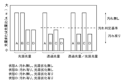
- FIG. 3 is a diagram showing an example of a light source light amount, a transmitted light amount, and a light amount ratio (transmitted light amount/light source light amount).
- 2 is a flowchart showing an example of the operation of the water quality analyzer 100. It is a flowchart which shows another example of operation of water quality analyzer 100. It is a flowchart which shows another example of operation of water quality analyzer 100.
- 3 is a diagram showing a configuration example of a measurement light detection section 30 and a concentration measurement section 32.
- FIG. 1 is a diagram showing an example of a water quality analysis device 100 according to one embodiment of the present invention.
- the water quality analyzer 100 measures the concentration of a substance to be measured contained in sample water.
- the water quality analyzer 100 of this example includes a light source 10, a flow cell 20, a light source monitor 50, a measurement light detection section 30, a concentration measurement section 32, a transmitted light detection section 70, a dirt detection section 40, and a cleaning section 60.
- the light source monitor 50, the measurement light detection section 30, and the transmitted light detection section 70 are devices that detect the amount of received light using a light receiving element such as a CCD or a photodiode.
- the amount of light refers to the total amount of light flux (lm/S) that passes through a predetermined surface within a predetermined unit time, but the intensity of light (cd) may also be used as the amount of light.
- the light source monitor 50, the measurement light detection section 30, and the transmitted light detection section 70 output electrical signals according to the detected amount of light.
- the light source monitor 50, the measurement light detection section 30, and the transmitted light detection section 70 may perform signal processing such as amplification or noise removal on the electrical signal.
- the light source 10 irradiates light 91 toward the flow cell 20.
- Flow cell 20 has a wall 22 and an interior space 24 .
- At least a portion of the wall portion 22 is made of a material that transmits at least a portion of the components of the light 91 irradiated by the light source 10 .
- At least a portion of the wall portion 22 is made of glass, for example.
- the wall portion 22 may include a window portion through which light enters or exits, and a support portion that supports the window portion. In this specification, a window portion through which light enters or exits may be referred to as a wall portion 22.
- Internal space 24 is surrounded by wall portion 22 . Sample water passes through the internal space 24 .
- the wall portion 22 has a cylindrical shape. In FIG. 1, a cross section of the wall portion 22 and the internal space 24 is schematically shown.
- the measurement light detection section 30 detects the measurement light 92 from the flow cell 20.
- the measurement light detection unit 30 measures the amount of measurement light 92 at at least one wavelength.
- the measurement light 92 is light that is emitted from the flow cell 20 when the light source 10 irradiates the light 91 with sample water present in the flow cell 20 .
- the measurement light 92 may include fluorescence emitted from the substance to be measured when the substance to be measured contained in the sample water is irradiated with the light 91 .
- the measurement light detection section 30 may measure the amount of measurement light 92 at a wavelength different from that of the light 91.
- the concentration measurement unit 32 measures the concentration of the substance to be measured contained in the sample water based on the measurement results from the measurement light detection unit 30.
- sample water include, but are not limited to, tap water, sewage water, seawater, and wastewater from factories.
- a fluorescent substance such as polycyclic aromatic hydrocarbons (hereinafter referred to as PAH)
- PAH polycyclic aromatic hydrocarbons
- the intensity of the light 91 or the measurement light 92 is attenuated by the dirt.
- the dirt on the wall portion 22 refers to the dirt on the window portion. Dirt on the wall 22 is, for example, foreign matter attached to the inner or outer surface of the wall 22. If the intensity of the light 91 or the measurement light 92 is attenuated, an error will occur in the measurement result of the concentration of the substance to be measured. Therefore, it is preferable to be able to accurately detect whether or not the wall portion 22 of the flow cell 20 is contaminated.
- the dirt detection unit 40 detects dirt on the wall portion 22.
- the dirt detection unit 40 may detect dirt on the wall portion 22 using a predetermined operation in the water quality analyzer 100 as a trigger. For example, when the cleaning section 60 cleans the wall section 22 of the flow cell 20, the dirt detection section 40 detects the dirt on the wall section 22 after cleaning.
- the cleaning unit 60 may clean the inner surface of the wall portion 22 by flowing a cleaning liquid into the internal space 24 of the flow cell 20, and may clean the wall portion 22 by bringing a brush or the like into contact with the inner or outer surface of the wall portion 22. Good too.
- the cleaning section 60 may clean the wall section 22 every time a set cleaning period elapses.
- the dirt detection unit 40 may notify the cleaning unit 60 that cleaning has not been completed when the degree of dirt on the wall portion 22 is outside the allowable range.
- the cleaning unit 60 may clean the wall portion 22 of the flow cell 20 again when receiving the notification.
- the dirt detection unit 40 may detect dirt on the wall portion 22 every time a set detection period elapses.
- the dirt detection section 40 detects dirt on the wall section 22 at every predetermined detection period, and when the degree of dirt on the wall section 22 falls outside the allowable range, the cleaning section 60 cleans the wall section 22. good.
- the dirt detection unit 40 may detect dirt on the wall portion 22 in response to instructions from a user or the like. In this case as well, the stain detection section 40 may cause the cleaning section 60 to clean the wall section 22 when the degree of contamination on the wall section 22 falls outside the allowable range.
- the light source 10 When the dirt detection unit 40 detects dirt on the wall 22, the light source 10 irradiates the flow cell 20 with light 91 having a predetermined wavelength component.
- the wavelength of the light 91 when detecting dirt may be different from the wavelength of the light 91 when measuring the fluorescence of the substance to be measured.
- the light source 10 may include a light source unit that emits light 91 for detecting dirt and a light source unit that emits light 91 for detecting fluorescence.
- the transmitted light detection unit 70 detects the transmitted light 94 that is transmitted through the flow cell 20 after the light 91 enters the flow cell 20 .
- the transmitted light detection unit 70 may detect the light 91 emitted from the flow cell 20 after going straight through the flow cell 20 as the transmitted light 94 .
- the wall 22 may be provided with a window through which the light 91 enters, a window through which the measurement light 92 exits, and a window through which the transmitted light exits.
- the transmitted light detection unit 70 detects the amount of transmitted light, which is the amount of transmitted light 94.
- the transmitted light detection section 70 may detect the amount of transmitted light of a set wavelength.
- the transmitted light detection section 70 outputs an electrical signal indicating the amount of transmitted light to the dirt detection section 40 .
- the intensity of light is attenuated by the dirt, so the amount of transmitted light 94 is reduced. Therefore, by detecting how much the amount of transmitted light 94 is attenuated with respect to the amount of light 91 emitted by the light source 10, the degree of dirt on the wall portion 22 can be estimated. On the other hand, due to factors such as deterioration of the light source 10, the amount of light 91 emitted from the light source 10 may change over time even if the setting value for the light source 10 is the same. When the amount of light 91 changes, the amount of transmitted light 94 also changes. Therefore, it is difficult to accurately detect dirt on the wall portion 22 from only the transmitted light 94.
- the water quality analyzer 100 of this example detects the amount of light from the light source, which is the amount of light 91 emitted by the light source 10, using the light source monitor 50.
- the light source monitor 50 detects the amount of light 91 from the light source before entering the flow cell 20 .
- the light source monitor 50 may receive branched light 93 obtained by branching a part of the light 91.
- the dirt detection unit 40 detects dirt on the wall portion 22 of the flow cell 20 based on the amount of light from the light source and the amount of transmitted light.
- the dirt detection unit 40 corrects the amount of transmitted light based on the amount of light from the light source, and detects dirt on the wall portion 22 based on the correction result. For example, the dirt detection unit 40 corrects the amount of transmitted light such that the smaller the amount of light from the light source is, the larger the amount of transmitted light is, and determines that the smaller the corrected amount of transmitted light is, the greater the degree of dirt on the wall portion 22 is.
- the stain detection unit 40 detects stains on the wall portion 22 based on the ratio of the amount of light from the light source to the amount of transmitted light (amount of transmitted light/amount of light source light).
- the dirt detection unit 40 determines that the smaller the light amount ratio, the greater the degree of dirt. In this way, by detecting dirt on the wall portion 22 using the amount of light from the light source and the amount of transmitted light, the influence of deterioration of the light source 10 and the like can be reduced, and dirt on the wall portion 22 can be detected with high accuracy.
- the amount of light from the light source and the amount of transmitted light may be measured without the sample water flowing through the flow cell 20.
- FIG. 2 is a diagram showing an example of the light source light amount, the transmitted light amount, and the light amount ratio (transmitted light amount/light source light amount).
- the vertical axis in FIG. 2 indicates the light amount or light amount ratio.
- FIG. 2 shows the light source light amount, the transmitted light amount, and the light amount ratio in a plurality of states A, B, C, and D.
- state A is the state at the time of shipment from the factory, in which the wall portion 22 is not dirty and the light source 10 is not deteriorated.
- State B is a state in which there is dirt on the wall portion 22 and the light source 10 has not deteriorated.
- State C is a state in which the wall portion 22 is clean and the light source 10 has deteriorated.
- State D is a state in which there is dirt on the wall portion 22 and the light source 10 has deteriorated.
- the degree of contamination of the wall portion 22 in states B and D is comparable, and the degree of deterioration of the light source 10 in states C and D is comparable.
- FIG. 2 shows the criteria for detecting the presence or absence of dirt on the wall 22 based only on the amount of transmitted light, and the criterion for detecting the presence or absence of dirt on the wall 22 based on the light amount ratio (transmitted light amount/light source light amount).
- the determination criteria are shown by broken lines. The determination criteria are set in advance by the user or the like. For example, if the amount of light or the ratio of light amounts is greater than the criterion, it is determined that there is no stain, and if the amount of light or the ratio of light amounts is less than the criterion, it is determined that there is stain.
- the influence of deterioration of the light source 10 can be reduced.
- dirt on the wall portion 22 can be detected with high accuracy by correcting the influence of deterioration of the light source 10.
- the dirt detection unit 40 may detect the presence or absence of dirt on the wall portion 22 by comparing the light amount ratio and dirt determination criteria.
- the dirt detection unit 40 may determine the degree of dirt based on the magnitude of the deviation between the light amount ratio and the dirt determination standard.
- FIG. 3 is a flowchart showing an example of the operation of the water quality analyzer 100.
- the water quality analyzer 100 starts measuring the concentration of the substance to be measured in the sample water in response to a predetermined trigger signal.
- the trigger signal may be input in response to an operation by a user, etc., may be automatically input in response to a change in the surrounding environment, may be automatically input every time a predetermined period elapses, or may be input automatically in response to a change in the surrounding environment. may be input depending on the factors.
- the concentration measurement unit 32 measures the sample water.
- the concentration measurement section 32 measures the concentration of the substance to be measured based on the measurement light 92 measured by the measurement light detection section 30.
- the measurement light 92 may be fluorescence emitted from the sample water.
- the concentration measurement section 32 can measure the concentration of the fluorescent substance based on the amount of measurement light 92.
- the water quality analyzer 100 continuously or intermittently measures the concentration of the substance to be measured in the sample water for a preset continuous use period.
- the cleaning section 60 cleans the inside of the flow cell 20 in a cleaning step S206.
- the cleaning section 60 may clean the flow cell 20 by flowing clean water or a cleaning liquid containing chemicals into the internal space 24 of the flow cell 20, and clean the flow cell 20 by sweeping the internal space 24 with a member such as a brush.
- the flow cell 20 may be washed using a combination of these methods.
- the stain detection unit 40 determines whether the cleaning of the flow cell 20 is completed.
- the dirt detection unit 40 may detect the presence or absence of dirt on the wall portion 22 of the flow cell 20, and if it is determined that there is no dirt, it may be determined that the cleaning has been completed. As shown in FIG. 2, the dirt detection unit 40 may determine the presence or absence of dirt by comparing the light amount ratio (transmitted light amount/light source light amount) with a predetermined dirt determination criterion.
- the amount of transmitted light and the amount of light from the light source may be measured while the internal space 24 of the flow cell 20 is filled with fresh water, and the amount of transmitted light and the amount of source light may be measured when the internal space 24 is not filled with liquid. may be measured.
- the water quality analyzer 100 may repeat the process from the measurement step S202, or may terminate the operation. If it is determined in the cleaning completion determination step S208 that the cleaning is not completed, the cleaning unit 60 repeats the process in the cleaning step S206. If the cleaning of the flow cell 20 is not completed within a set period from the start of cleaning of the flow cell 20, the dirt detection unit 40 may output a notification indicating that the cleaning has not been completed. In this case, the water quality analyzer 100 may repeat the processing from the measurement step S202, or may terminate the operation.
- the cleaning unit 60 may select a cleaning method for the flow cell 20 based on at least one of the amount of light from the light source and the amount of transmitted light.
- the selection of the cleaning method may be the selection of the characteristics of the cleaning liquid used for cleaning, or the selection of the tool used for cleaning (whether to use a brush or the cleaning liquid, etc.).
- the cleaning section 60 may select a cleaning method depending on the degree of contamination determined from the light amount ratio (light source light amount and transmitted light amount). In this case, the light amount ratio may be measured in the cleaning step S206.
- the cleaning unit 60 may adjust the pH of the cleaning liquid to be flowed into the flow cell 20 depending on the degree of contamination. The greater the degree of contamination, the greater the pH of the cleaning liquid may deviate from the neutral value. The degree to which the pH is changed depending on the degree of dirt may be determined experimentally in advance and set in the cleaning section 60.
- the cleaning unit 60 may select a cleaning method based on the history of sample water that has been passed through the flow cell 20 in the past.
- the cleaning unit 60 may select a cleaning method depending on the type of sample water flowed in the continuous use step S204.
- the type of sample water may be the type of substance contained in the sample water. For example, whether to use an acidic or alkaline cleaning liquid may be selected depending on the type of sample water. Since it is possible to estimate the contaminant substance adhering to the flow cell 20 depending on the type of sample water, the cleaning section 60 may select a cleaning liquid depending on the type of sample water. What kind of cleaning liquid should be selected for each substance may be set in advance for the cleaning unit 60.
- the portion through which the cleaning liquid flows is preferably formed of a material that does not change in quality even when an acidic or alkaline cleaning liquid flows therethrough.
- the cleaning section 60 may estimate the type of substance attached to the wall section 22 based on the light amount ratio (light source light amount and transmitted light amount) at multiple wavelengths, and select a cleaning method according to the estimation result.
- the cleaning unit 60 may estimate the type of substance attached to the wall portion 22 by comparing the shape of the spectrum of the light amount ratio and the transmission spectrum determined according to the type of each substance. By using the light amount ratio corrected for the deterioration of the light source 10, the type of substance attached to the wall portion 22 can be estimated with high accuracy.
- FIG. 4 is a flowchart showing another example of the operation of the water quality analyzer 100.
- the operation of this example differs from the operation example of FIG. 3 in that it further includes a period elapse determination step S210 and a cleaning method change step S212.
- the other steps are similar to the example of FIG.
- the period elapsed determination step S210 is performed.
- the stain detection unit 40 determines whether a set period has elapsed since the start of cleaning the flow cell 20. If the set period has not yet elapsed, the stain detection unit 40 causes the cleaning unit 60 to repeat the process of cleaning step S206. If the cleaning is not completed within the set period, the stain detection section 40 changes the cleaning method of the cleaning section 60 in the cleaning method changing step S212. The cleaning unit 60 may select a more powerful cleaning method if the cleaning is not completed within the set period.
- the cleaning unit 60 may perform cleaning again using a cleaning liquid containing a chemical or a surfactant. Further, the cleaning unit 60 may adjust the pH of the cleaning liquid when cleaning is not completed within a set period using the cleaning liquid.
- FIG. 5 is a flowchart showing another example of the operation of the water quality analyzer 100.
- the operation of this example differs from the operation example of FIG. 3 or 4 in that it further includes a dirt detection step S205.
- Other steps are similar to the example of FIG. 3 or 4.
- FIG. 5 shows an example in which the dirt detection step S205 is added to the operation example in FIG. 3, the dirt detection step S205 may be added to the operation example in FIG.
- the stain detection unit 40 of this example detects stains on the wall portion 22 using the amount of transmitted light when sample water is flowing through the flow cell 20. Specifically, dirt on the wall portion 22 is detected using the light source light amount and the transmitted light amount measured within the continuous use period in the continuous use step S204.
- the dirt detection unit 40 may detect dirt on the wall portion 22 at predetermined intervals during the period of continuous use. In the example of FIG. 5, dirt on the wall portion 22 is detected in the dirt detection step S205 during the period of continuous use. If it is determined in the dirt detection step S205 that there is no dirt on the wall portion 22, the water quality analyzer 100 continues the process in the continuous use step S204. If it is determined in the dirt detection step S205 that there is dirt on the wall portion 22, the water quality analyzer 100 performs the cleaning step S206 and subsequent processes. The processing after the cleaning step S206 is similar to the example shown in FIG. 3 or 4.
- FIG. 6 is a diagram showing a configuration example of the measurement light detection section 30 and the concentration measurement section 32.
- the measurement light detection section 30 of this example includes a fluorescence detection section 33 and a scattered light detection section 31.
- the concentration measurement section 32 includes a signal processing section 35 and a turbidity measurement section 34.
- the water quality analyzer 100 of this example includes a light source 10-1 and a light source 10-2.
- the light source 10-1 is a light source that emits light 91-1 for measuring scattered light (measuring light 92-1)
- the light source 10-2 is a light source for measuring fluorescence (measuring light 92-2). This is a light source that emits light 91-2.
- Light 91-1 and light 91-2 may have different wavelength components.
- Light 91-1 from light source 10-1 is also used to measure transmitted light 94. That is, part of the light 91-1 is emitted as scattered light, and the other part is emitted as transmitted light.
- the water quality analyzer 100 of this example measures the concentration of fluorescent substances contained in sample water based on the amount of fluorescence (measurement light 92-2).
- the amount of light 91-2 or measurement light 92-2 may be attenuated due to light scattering or absorption from the suspended matter (particles). This phenomenon is called the inner filter effect. Due to the inner filter effect, the accuracy of measuring fluorescence intensity may deteriorate in an environment with a high concentration of suspended solids (hereinafter referred to as turbidity).
- the water quality analyzer 100 of this example corrects the amount of the measured measurement light 92-2 based on the turbidity of the sample water in order to improve the measurement accuracy of fluorescence intensity.
- the water quality analyzer 100 measures the turbidity of sample water as well as the fluorescence intensity.
- the water quality analyzer 100 measures the turbidity of sample water from the amount of scattered light or transmitted light from the sample water.
- the scattered light detection section 31 detects the amount of scattered light of the sample water.
- the amount of transmitted light of the sample water may be detected by the transmitted light detection section 70 shown in FIG. 1 .
- the light source 10-1 irradiates the sample water inside the flow cell 20 with light 91-1, which is infrared light.
- the light source 10-1 is, for example, an LED (Light Emitting Diode) or a laser irradiation device.
- scattered light By irradiating the sample water inside the flow cell 20 with the light 91-1, scattered light (measurement light 92-1) or transmitted light 94 (see FIG. 1) is generated. Scattered light is caused by light scattering by suspended matter contained in the sample water. The higher the concentration of suspended solids, the greater the amount of scattered light. Transmitted light 94 is light that is not absorbed or scattered by suspended matter in the sample water. The higher the concentration of suspended matter is, the more the amount of transmitted light 94 is attenuated.
- the turbidity measurement unit 34 determines the turbidity of the sample water based on at least one of the amount of measurement light 92-1 detected by the scattered light detection unit 31 and the amount of transmitted light 94 detected by the transmitted light detection unit 70. may be measured.
- the turbidity measurement unit 34 may measure the turbidity based on the amount of one of the measurement light 92-1 and the transmitted light 94. As described above, since the light amounts of the measurement light 92-1 and the transmitted light 94 change depending on the turbidity, the turbidity can be estimated from these light amounts.
- the turbidity measurement unit 34 may calculate the turbidity using the ratio of the light amount of the measurement light 92-1 and the transmitted light 94 (light amount of the measurement light 92-1/light amount of the transmitted light 94). The higher the turbidity, the higher the ratio of light amounts.
- the light source 10-2 irradiates the sample water inside the flow cell 20 with light 91-2.
- the light 91-2 is, for example, ultraviolet light.
- the light source 10-2 is, for example, a xenon flash lamp, an LED, or a laser irradiation device.
- the light source 10-2 may include an optical filter inside. Since the light source 10-2 includes an optical filter, the light source 10-2 can irradiate the flow cell 20 with light in a predetermined wavelength range of the light 91-2.
- the substance to be measured is PAH. PAH emits fluorescence most efficiently when the wavelength of excitation light is around 250 nm. Therefore, the transmission wavelength of the optical filter of the light source 10-2 is set to, for example, 200 nm or more and 300 nm or less.
- the fluorescence detection unit 33 detects the amount of measurement light 92-2.
- the fluorescence detection section 33 may include an optical filter inside. Since it includes an optical filter, the fluorescence detection section 33 can receive light in a predetermined wavelength range of the measurement light 92-2.
- the substance to be measured is PAH.
- the transmission wavelength of the optical filter inside the fluorescence detection section 33 is set to, for example, 300 nm or more and 400 nm or less.
- the signal processing unit 35 calculates the concentration of the fluorescent substance contained in the sample water from the amount of measurement light 92-2 detected by the fluorescence detection unit 33. As described above, the light intensity of the measurement light 92-2 is attenuated by the turbidity of the sample water. The signal processing section 35 corrects the light intensity of the measurement light 92-2 based on the turbidity measured by the turbidity measurement section 34, and calculates the concentration of the fluorescent substance. The relationship between turbidity and correction amount may be determined experimentally in advance and set in the signal processing unit 35. Through such processing, the water quality analyzer 100 can accurately measure the concentration of the fluorescent substance in the sample water.
- the amount of transmitted light may attenuate depending on the turbidity of the sample water. be. In this case, the accuracy of detecting dirt on the wall portion 22 may deteriorate.
- the stain detection unit 40 may detect stains on the wall portion 22 of the flow cell 20 using the amount of scattered light (scattered light amount) detected by the scattered light detection unit 31 in addition to the amount of transmitted light and the amount of light from the light source.
- the dirt detection unit 40 may use the same amount of transmitted light as the turbidity measurement.
- the dirt detection section 40 may use the turbidity calculated by the turbidity measurement section 34 instead of the amount of scattered light.
- the dirt detection unit 40 may correct the amount of transmitted light using the amount of scattered light. In other words, when the amount of scattered light is large, it is considered that the amount of transmitted light is greatly attenuated by suspended matter, so the amount of transmitted light may be corrected to a larger value as the amount of scattered light increases. Thereby, the influence of the turbidity of the sample water is reduced, and stains on the wall portion 22 can be detected with high accuracy.
- the dirt detection unit 40 may determine the dirt on the wall portion 22 on the condition that the amount of scattered light or turbidity is equal to or less than a reference value.
- the stain detection unit 40 may determine the stain on the wall portion 22 on the condition that the attenuation of the amount of transmitted light due to the sample water is small. Thereby, the influence of the turbidity of the sample water is reduced, and stains on the wall portion 22 can be detected with high accuracy.
- the amount of transmitted light used for measuring turbidity and the amount of transmitted light used for measuring dirt can be detected by a common transmitted light detection section 70. Further, the light source 10 used for measuring turbidity and the light source 10 used for assuming dirt can be shared. Therefore, the number of constituent members of the water quality analyzer 100 can be reduced.
- SYMBOLS 10 Light source, 20... Flow cell, 22... Wall part, 24... Inner space, 30... Measurement light detection part, 31... Scattered light detection part, 32... Concentration measurement Part, 33... Fluorescence detection unit, 34... Turbidity measurement unit, 35... Signal processing unit, 40... Dirt detection unit, 50... Light source monitor, 60... Cleaning unit, 70 ...Transmitted light detection unit, 91...Light, 92...Measurement light, 93...Branched light, 94...Transmitted light, 100...Water quality analyzer
Landscapes
- Chemical & Material Sciences (AREA)
- Health & Medical Sciences (AREA)
- Life Sciences & Earth Sciences (AREA)
- Immunology (AREA)
- Analytical Chemistry (AREA)
- Biochemistry (AREA)
- General Health & Medical Sciences (AREA)
- General Physics & Mathematics (AREA)
- Physics & Mathematics (AREA)
- Pathology (AREA)
- Engineering & Computer Science (AREA)
- Mechanical Engineering (AREA)
- Food Science & Technology (AREA)
- Medicinal Chemistry (AREA)
- Optical Measuring Cells (AREA)
- Investigating Or Analysing Materials By Optical Means (AREA)
Abstract
Description
特許文献1 特許第6436266号公報
特許文献2 特開2006-194659号公報
Claims (12)
- 試料水に含まれる測定対象物質の濃度を測定する水質分析装置であって、
光を透過する壁部と、前記壁部に囲まれた内部空間とを有し、前記試料水が前記内部空間を通過するフローセルと、
前記フローセルに向けて光を照射する光源と、
前記光源が照射した前記光の光量である光源光量を検出する光源モニタと、
前記フローセルを透過した透過光の光量である透過光量を検出する透過光検出部と、
前記光源光量と前記透過光量とに基づいて、前記フローセルの前記壁部の汚れを検出する汚れ検出部と
を備える水質分析装置。 - 前記汚れ検出部は、前記光源光量と前記透過光量との比に基づいて、前記壁部の汚れを検出する
請求項1に記載の水質分析装置。 - 前記フローセルの前記壁部の汚れを洗浄する洗浄部を更に備え、
前記汚れ検出部は、前記フローセルの洗浄後に検出した前記光源光量と前記透過光量とに基づいて、前記フローセルの洗浄が終了したか否かを判定する
請求項1に記載の水質分析装置。 - 前記汚れ検出部は、前記フローセルの洗浄開始から設定期間内に洗浄が終了しない場合に、洗浄が終了しない旨を示す通知を出力する
請求項3に記載の水質分析装置。 - 前記汚れ検出部は、前記フローセルの洗浄開始から設定期間内に洗浄が終了しない場合に、前記洗浄部における洗浄方法を変更させる
請求項3に記載の水質分析装置。 - 前記洗浄部は、前記光源光量および前記透過光量の少なくとも一方に基づいて、前記フローセルの洗浄方法を選択する
請求項3に記載の水質分析装置。 - 前記洗浄部は、前記光源光量と前記透過光量との比に基づいて、前記フローセルに流す洗浄液のpHを調整する
請求項6に記載の水質分析装置。 - 前記洗浄部は、過去に前記フローセルに流した前記試料水の履歴に基づいて、前記フローセルの洗浄方法を選択する
請求項3に記載の水質分析装置。 - 前記汚れ検出部は、前記フローセルに前記試料水を流さない状態での前記透過光量を用いて、前記壁部の汚れを検出する
請求項1から8のいずれか一項に記載の水質分析装置。 - 前記汚れ検出部は、前記フローセルに前記試料水を流した状態での前記透過光量を用いて、前記壁部の汚れを検出する
請求項1から8のいずれか一項に記載の水質分析装置。 - 前記試料水からの散乱光の光量である散乱光量を検出する散乱光検出部を更に備え、
前記汚れ検出部は、前記散乱光量に更に基づいて、前記フローセルの前記壁部の汚れを検出する
請求項10に記載の水質分析装置。 - 前記散乱光検出部が検出した前記散乱光量、および、前記透過光検出部が検出した前記透過光量の少なくとも一方に基づいて、前記試料水の濁度を測定する濁度測定部を更に備える
請求項11に記載の水質分析装置。
Priority Applications (4)
| Application Number | Priority Date | Filing Date | Title |
|---|---|---|---|
| JP2023574542A JP7613613B2 (ja) | 2022-05-13 | 2022-05-13 | 水質分析装置 |
| KR1020237040602A KR20230172600A (ko) | 2022-05-13 | 2022-05-13 | 수질 분석 장치 |
| PCT/JP2022/020296 WO2023218672A1 (ja) | 2022-05-13 | 2022-05-13 | 水質分析装置 |
| CN202280036948.5A CN117413169A (zh) | 2022-05-13 | 2022-05-13 | 水质分析装置 |
Applications Claiming Priority (1)
| Application Number | Priority Date | Filing Date | Title |
|---|---|---|---|
| PCT/JP2022/020296 WO2023218672A1 (ja) | 2022-05-13 | 2022-05-13 | 水質分析装置 |
Publications (1)
| Publication Number | Publication Date |
|---|---|
| WO2023218672A1 true WO2023218672A1 (ja) | 2023-11-16 |
Family
ID=88729913
Family Applications (1)
| Application Number | Title | Priority Date | Filing Date |
|---|---|---|---|
| PCT/JP2022/020296 Ceased WO2023218672A1 (ja) | 2022-05-13 | 2022-05-13 | 水質分析装置 |
Country Status (4)
| Country | Link |
|---|---|
| JP (1) | JP7613613B2 (ja) |
| KR (1) | KR20230172600A (ja) |
| CN (1) | CN117413169A (ja) |
| WO (1) | WO2023218672A1 (ja) |
Citations (5)
| Publication number | Priority date | Publication date | Assignee | Title |
|---|---|---|---|---|
| JPH04125446A (ja) * | 1990-09-17 | 1992-04-24 | Shimadzu Corp | 分光光度計 |
| JPH05164762A (ja) * | 1991-12-17 | 1993-06-29 | Hitachi Ltd | 自動分析装置および容器の汚染判定方法 |
| JP2015184018A (ja) * | 2014-03-20 | 2015-10-22 | 東レ株式会社 | 赤外吸収スペクトル作成方法、検量線作成方法、ならびにこれらを用いた溶液濃度定量方法および溶液濃度測定装置 |
| JP2019015513A (ja) * | 2017-07-03 | 2019-01-31 | 株式会社島津製作所 | 検出装置 |
| WO2020079800A1 (ja) * | 2018-10-18 | 2020-04-23 | 株式会社島津製作所 | 検出装置 |
Family Cites Families (5)
| Publication number | Priority date | Publication date | Assignee | Title |
|---|---|---|---|---|
| JPH052055U (ja) * | 1991-06-24 | 1993-01-14 | 横河電機株式会社 | 吸光度式分析計 |
| JP2008064612A (ja) * | 2006-09-07 | 2008-03-21 | Kurita Water Ind Ltd | 水質測定方法及び水質測定装置 |
| CN101910821B (zh) * | 2007-12-04 | 2012-09-05 | 粒子监测系统有限公司 | 非正交粒子检测系统和方法 |
| JP2013088302A (ja) * | 2011-10-19 | 2013-05-13 | Dkk Toa Corp | 検出器及び水質測定装置 |
| EP3355048B1 (en) * | 2016-05-19 | 2021-05-05 | Fuji Electric Co., Ltd. | Water quality analyzer |
-
2022
- 2022-05-13 KR KR1020237040602A patent/KR20230172600A/ko active Pending
- 2022-05-13 WO PCT/JP2022/020296 patent/WO2023218672A1/ja not_active Ceased
- 2022-05-13 CN CN202280036948.5A patent/CN117413169A/zh active Pending
- 2022-05-13 JP JP2023574542A patent/JP7613613B2/ja active Active
Patent Citations (5)
| Publication number | Priority date | Publication date | Assignee | Title |
|---|---|---|---|---|
| JPH04125446A (ja) * | 1990-09-17 | 1992-04-24 | Shimadzu Corp | 分光光度計 |
| JPH05164762A (ja) * | 1991-12-17 | 1993-06-29 | Hitachi Ltd | 自動分析装置および容器の汚染判定方法 |
| JP2015184018A (ja) * | 2014-03-20 | 2015-10-22 | 東レ株式会社 | 赤外吸収スペクトル作成方法、検量線作成方法、ならびにこれらを用いた溶液濃度定量方法および溶液濃度測定装置 |
| JP2019015513A (ja) * | 2017-07-03 | 2019-01-31 | 株式会社島津製作所 | 検出装置 |
| WO2020079800A1 (ja) * | 2018-10-18 | 2020-04-23 | 株式会社島津製作所 | 検出装置 |
Also Published As
| Publication number | Publication date |
|---|---|
| CN117413169A (zh) | 2024-01-16 |
| JP7613613B2 (ja) | 2025-01-15 |
| JPWO2023218672A1 (ja) | 2023-11-16 |
| KR20230172600A (ko) | 2023-12-22 |
Similar Documents
| Publication | Publication Date | Title |
|---|---|---|
| US5922606A (en) | Fluorometric method for increasing the efficiency of the rinsing and water recovery process in the manufacture of semiconductor chips | |
| JP5683836B2 (ja) | 光学測定キュベットの汚染物質の検出方法 | |
| KR20190015382A (ko) | 액체 매질 중의 물질의 농도를 결정하기 위한 방법 및 장치 | |
| JP7448090B2 (ja) | 水質分析装置 | |
| JP2013506839A (ja) | 全有機炭素(toc)流体センサー | |
| JP7613613B2 (ja) | 水質分析装置 | |
| JP4359769B2 (ja) | センサの汚れ検出方法 | |
| JP2001033388A (ja) | クロロフィルa濃度測定方法及びその装置 | |
| JP2006339598A (ja) | 半導体基板の洗浄装置 | |
| US20060160239A1 (en) | Method of measuring a level of contamination in a chemical solution and systems thereof | |
| US10845309B2 (en) | Blackened optical component without fluorescence | |
| WO2019075014A1 (en) | FILTERED AND INTEGRATED SENSOR MEASUREMENT FOR DETERMINING PROCESS CONDITION AND METHOD THEREFOR | |
| TWI384217B (zh) | 懸浮固體濃度及化學需氧量的量測方法與系統 | |
| JP5563957B2 (ja) | 分析装置 | |
| JP2024502795A (ja) | 自動化学分析装置におけるキュベットの較正および検証 | |
| CA3087055C (en) | Blackened optical component without fluorescence | |
| CN117517198A (zh) | 水质分析装置 | |
| JPH08271519A (ja) | 自動化学分析装置における測光系の精度確認方法 | |
| KR102858432B1 (ko) | 총유기탄소 측정장치 및 그 총유기탄소 측정장치의 유로 세정 방법 | |
| JP3225091B2 (ja) | 被洗浄物の洗浄度評価方法及び洗浄度評価装置 | |
| US12298237B2 (en) | Large dynamic range kinetic monitor | |
| JP2009210275A (ja) | 自動分析装置 | |
| JP2024176264A (ja) | 水質分析装置 | |
| CN118225773A (zh) | 水质分析装置 | |
| KR20070079695A (ko) | 반도체 웨이퍼의 세정 설비 |
Legal Events
| Date | Code | Title | Description |
|---|---|---|---|
| WWE | Wipo information: entry into national phase |
Ref document number: 202280036948.5 Country of ref document: CN |
|
| ENP | Entry into the national phase |
Ref document number: 20237040602 Country of ref document: KR Kind code of ref document: A |
|
| WWE | Wipo information: entry into national phase |
Ref document number: 1020237040602 Country of ref document: KR |
|
| ENP | Entry into the national phase |
Ref document number: 2023574542 Country of ref document: JP Kind code of ref document: A |
|
| 121 | Ep: the epo has been informed by wipo that ep was designated in this application |
Ref document number: 22941748 Country of ref document: EP Kind code of ref document: A1 |
|
| NENP | Non-entry into the national phase |
Ref country code: DE |
|
| 122 | Ep: pct application non-entry in european phase |
Ref document number: 22941748 Country of ref document: EP Kind code of ref document: A1 |