WO2023218643A1 - 映像生成装置、及びコンピュータが読み取り可能な記憶媒体 - Google Patents
映像生成装置、及びコンピュータが読み取り可能な記憶媒体 Download PDFInfo
- Publication number
- WO2023218643A1 WO2023218643A1 PCT/JP2022/020231 JP2022020231W WO2023218643A1 WO 2023218643 A1 WO2023218643 A1 WO 2023218643A1 JP 2022020231 W JP2022020231 W JP 2022020231W WO 2023218643 A1 WO2023218643 A1 WO 2023218643A1
- Authority
- WO
- WIPO (PCT)
- Prior art keywords
- event
- viewpoint
- video
- data
- unit
- Prior art date
- Legal status (The legal status is an assumption and is not a legal conclusion. Google has not performed a legal analysis and makes no representation as to the accuracy of the status listed.)
- Ceased
Links
Images








Classifications
-
- G—PHYSICS
- G05—CONTROLLING; REGULATING
- G05B—CONTROL OR REGULATING SYSTEMS IN GENERAL; FUNCTIONAL ELEMENTS OF SUCH SYSTEMS; MONITORING OR TESTING ARRANGEMENTS FOR SUCH SYSTEMS OR ELEMENTS
- G05B23/00—Testing or monitoring of control systems or parts thereof
- G05B23/02—Electric testing or monitoring
- G05B23/0205—Electric testing or monitoring by means of a monitoring system capable of detecting and responding to faults
- G05B23/0218—Electric testing or monitoring by means of a monitoring system capable of detecting and responding to faults characterised by the fault detection method dealing with either existing or incipient faults
- G05B23/0221—Preprocessing measurements, e.g. data collection rate adjustment; Standardization of measurements; Time series or signal analysis, e.g. frequency analysis or wavelets; Trustworthiness of measurements; Indexes therefor; Measurements using easily measured parameters to estimate parameters difficult to measure; Virtual sensor creation; De-noising; Sensor fusion; Unconventional preprocessing inherently present in specific fault detection methods like PCA-based methods
-
- B—PERFORMING OPERATIONS; TRANSPORTING
- B23—MACHINE TOOLS; METAL-WORKING NOT OTHERWISE PROVIDED FOR
- B23Q—DETAILS, COMPONENTS, OR ACCESSORIES FOR MACHINE TOOLS, e.g. ARRANGEMENTS FOR COPYING OR CONTROLLING; MACHINE TOOLS IN GENERAL CHARACTERISED BY THE CONSTRUCTION OF PARTICULAR DETAILS OR COMPONENTS; COMBINATIONS OR ASSOCIATIONS OF METAL-WORKING MACHINES, NOT DIRECTED TO A PARTICULAR RESULT
- B23Q17/00—Arrangements for observing, indicating or measuring on machine tools
- B23Q17/24—Arrangements for observing, indicating or measuring on machine tools using optics or electromagnetic waves
- B23Q17/2409—Arrangements for indirect observation of the working space using image recording means, e.g. a camera
Definitions
- the present invention relates to a video generation device and a computer readable storage medium.
- a data collection device called a data logger.
- a large number of data loggers are installed in the factory to record the status of the machines in the factory.
- a PLC Programmable Logic Controller
- a numerical control device that controls a machine tool also include a recording section therein and store control information and status information.
- Patent Document 1 states, ⁇ When the time load means acquires the control data acquired from the control device, the image data acquired from the camera, and the acoustic data acquired from the controlled device, it calculates the time at the time when each data was acquired. The added time-added control data, time-added image data, and time-added audio data are created and stored in a temporary file, and then the log data forming means creates the time-added control data, time-added sound data, and time-added control data stored in the temporary file.
- the time-added control data, time-added image data, and time-added audio data of the set closest in time are read out, and log data having time, control data, image data, and audio data is formed. By doing so, each piece of data can be played back while being synchronized.”
- images, sounds, and logs of a device to be controlled are played back while being synchronized by time.
- Patent Document 2 states that ⁇ a camera that photographs the robot is connected to the controller, and image data indicating the behavior of the robot obtained by photographing is supplied to the controller in the form of electrical signals''; ) occurs, an error record related to the error is created separately from the operation log.” According to Patent Document 2, when an event occurs when an image is photographed, the event and the image are recorded in association with each other.
- Patent Document 1 displays an image and a log at the same time, and Patent Document 2 records a log (data) when an event occurs. If you have logs and images from when the error occurred, the situation at the time of the error can be clarified and it will be useful in investigating the cause of the error. Similarly, if images with good visibility are created, they can be used to maintain industrial machinery and improve productivity.
- An image generation device that is an aspect of the present disclosure includes a data acquisition unit that acquires data indicating a mechanical state of an industrial machine, and a trigger event that searches for data indicating a state of the industrial machine and indicates a work performed on the industrial machine. and a viewpoint determination section that detects the viewpoint and determines a viewpoint corresponding to the trigger event, and an image generation section that generates an image of the industrial machine based on the viewpoint determined by the viewpoint determination section.
- a storage medium which is an aspect of the present disclosure, is executed by one or more processors to obtain data indicating the state of an industrial machine, search for data indicating the state of the industrial machine, and execute the process by the industrial machine. processor-readable instructions for detecting a trigger event indicative of a task performed, determining a viewpoint corresponding to the trigger event, and generating a video based on the determination of the viewpoint;
- FIG. 3 is a diagram showing the scope of application of the video generation device.
- 1 is a block diagram of a video generation device according to a first disclosure
- FIG. It is a conceptual model of the viewpoint determination unit of the first disclosure.
- FIG. 2 is a block diagram of a video generation device according to a second disclosure. It is a conceptual model of the viewpoint determination part of the second disclosure.
- FIG. 3 is a diagram showing an example of an event set. It is a figure which shows an example of the operation
- FIG. 3 is a diagram illustrating an example of a video generated by a video generation unit.
- FIG. 3 is a diagram showing an example of work before starting machining in a machining center.
- FIG. 3 is a diagram illustrating an example of a video generated by a video generation unit. It is a figure which shows the trigger event and event set with respect to workpiece
- FIG. 3 is a diagram showing a trigger event and an event set for workpiece measurement (hole-to-hole measurement).
- FIG. 3 is a diagram illustrating a method of searching for an event set.
- FIG. 3 is a diagram showing the relationship between work units and viewpoints.
- FIG. 3 is a diagram showing an example of a seek bar in which work units are arranged on a time axis.
- FIG. 3 is a diagram illustrating an example in which two videos are combined into one.
- FIG. 2 is a hardware configuration diagram of a video generation device.
- the video generation device 100 acquires data indicating the status of industrial machines placed in a factory.
- the video generation device 100 uses already accumulated data to determine the viewpoint of the video showing the operation of the industrial machine.
- Target industrial machinery includes, but is not limited to, machine tools, numerical control devices, and robots.
- the video generation device 100 is applied to an information processing device such as a PC (personal computer), a server, or a mobile terminal.
- the video generation device 100 is a PC used by a factory manager, a server on the cloud, a PC used by an operator of a machine manufacturer or a control machine manufacturer, and a PC used by a factory manager. This applies to, but is not limited to, the mobile terminal used.
- the video generated by the video generation device 100 is utilized for management of industrial machinery (maintenance, production management, etc.). Further, the video generation device 100 may be applied to an information processing device such as a numerical control device or a PLC (Programmable Logic Controller).
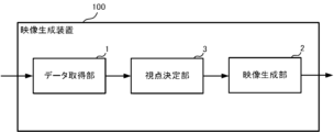
- FIG. 2 is a block diagram of the video generation device 100 of the first disclosure.
- the video generation device 100 includes a data acquisition section 1, a video generation section 2, and a viewpoint determination section 3.
- the data acquisition unit 1 acquires data regarding industrial machinery.
- the data acquired by the data acquisition unit 1 includes industrial machine status information, operation input information, industrial machine control information, and the like.
- numerical control devices and machine tools are taken as examples of industrial machines.
- the status information of industrial machines includes the numerical control device mode, tool offset amount, alarm, time, number of parts to be machined, modal information, position information (coordinate system), machine tool power consumption, servo motor load, and sensor information. This includes measured data (temperature, pressure), etc.
- the operation input information is an operation input from an operator to a touch panel, a button, a dial, a handle, etc.
- the video generation unit 2 uses existing simulation technology to generate a simulation video showing the operation of the industrial machine.
- the viewpoint of the simulation video can be switched.
- an example of generating a simulation video will be given, but the video generated by the video generation unit 2 may be a two-dimensional video based on the result of the viewpoint determination unit 3 instead of the simulation video.
- the viewpoint determination unit 3 determines the viewpoint of the simulation video generated by the video generation unit 2.
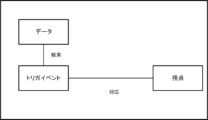
- FIG. 3 is a conceptual model of the viewpoint determination unit 3.
- the viewpoint determination unit 3 monitors the data acquired by the data acquisition unit 1 and detects a trigger event.
- the viewpoint determination unit 3 determines a viewpoint corresponding to the detected trigger event. A specific example of the trigger event will be described later.
- the video generation unit 2 generates a simulation video at the viewpoint determined by the viewpoint determination unit 3. Furthermore, a two-dimensional image may be generated based on the result of the viewpoint determination unit 3 instead of the simulation video. This creates a recorded video from a viewpoint suitable for checking the operation of industrial machinery.
- the video generation device 100 of the first disclosure acquires data regarding an industrial machine, detects a trigger event, and generates a recorded video from a viewpoint suitable for checking the operation of the industrial machine. According to the present disclosure, it is possible to change the viewpoint of a video according to the work of an industrial machine and generate a video with high visibility.
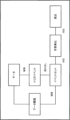
- FIG. 4 is a block diagram of the video generation device 100 of the second disclosure.
- the video generation device 100 includes a data acquisition section 1, a video generation section 2, a data history storage section 7, a viewpoint determination section 3, and an event set storage section 8.
- the video generation device 100 of the second disclosure includes a data history storage section 7 and an event set storage section 8.
- the data history storage unit 7 stores the history of data acquired by the data acquisition unit 1.
- the event set storage unit 8 stores combinations of data (event sets) that occur when a task is executed.
- FIG. 5 is a conceptual model of the viewpoint determination unit 3.
- the viewpoint determination unit 3 searches the data acquired by the data acquisition unit 1 and detects a trigger event.
- the viewpoint determining unit 3 reads out the event set corresponding to the detected trigger event, searches past data stored in the data history storage unit 7, and determines whether the event set corresponding to the detected trigger event has occurred in the past. Search for whether or not. If an event set corresponding to the detected trigger event has occurred in the past, it is determined that a certain task has been executed.
- the event set corresponds to a unit of work from the start to the end of the work.
- an event that occurs at the start of a task is referred to as a start event.
- One unit of work is from the start event to the trigger event.
- a specific example of the event set will be described later.
- the video generation section 2 generates a video based on the result of the viewpoint determination section 3. Note that the time at which the event occurred may be added to the video generated by the video generation unit 2. This time can be used for creating a seek bar and merging with other video, which will be described later.
- the video generation device 100 of the second disclosure determines the viewpoint depending on whether an event (trigger event and event set) associated with a task has occurred.
- the video generation device 100 generates a simulation video based on the determined viewpoint. By switching the viewpoint, images with high visibility can be generated.
- FIG. 6 is an example of an event set.
- the trigger event "cycle start button press” consists of three events: “press button to change NC mode to MEM”, “display automatic operation screen”, and "press cycle start button”. It is tied to an event set.
- the viewpoint determining unit 3 detects "pressing the cycle start button” and “pressing the button to change the NC mode to MEM” from the operation signal.
- the "display of the automatic driving screen” can be detected from the “screen ID” included in the history of operation signals.
- "Screen ID” is an ID assigned to each screen. It can be detected from the “screen ID” that the “autonomous driving screen” has been displayed. If the events are executed in the order defined in the event set, the viewpoint determining unit 3 can determine that the operation of "start machining" has been executed. Note that in the above description, the order of occurrence of events is fixed, but the order may be changed.
- the tool As a preparation before starting machining, move the tool to the machining start position in rapid traverse.
- the tool When machining is performed using a new machining program that has no prior machining experience, the tool is generally stopped temporarily at the machining start position or decelerated by performing a feed rate override operation on the control panel of the industrial machine. If the distance between the workpiece and the tool at the machining start position is the expected distance, it means that the "machining program" created by the programmer and the settings for "tool offset” and "workpiece coordinate settings” set at the machining site are correct. This is because it can be judged. Images that make it easy to visually check the distance between the workpiece and the tool are useful before starting machining.
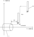
- FIG. 7 shows an example of a lathe.
- the Z-axis is generally parallel to the rotational axis of the main shaft
- the X-axis is the direction of the thumb in a right-handed orthogonal coordinate system with the Z-axis as the middle finger.
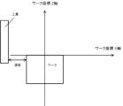
- a viewpoint perpendicular to the XZ plane is good.
- FIG. 8 shows an image generated from a viewpoint perpendicular to the XZ plane. By switching the viewpoint, you can easily see the distance between the workpiece and the tool. Note that the video in FIG. 8 is a two-dimensional image based on the result of the viewpoint determination unit 3.
- FIG. 9 shows an example of a machining center.
- the tool moves rapidly to the cutting start position and then either "temporarily stops” or “decelerates.”
- the tool that starts cutting moves in parallel to the X-axis of the workpiece coordinate system.
- the viewpoint is perpendicular to the XZ plane, the distance between the tool and the workpiece can be easily confirmed.
- FIG. 10 shows an image generated from a viewpoint perpendicular to the XZ plane. By switching the viewpoint, you can easily see the distance between the workpiece and the tool.
- the video in FIG. 10 is a two-dimensional image based on the result of the viewpoint determination unit 3.
- the viewpoint determination unit 3 may analyze the machining program and determine the viewpoint based on the moving direction of the tool.
- FIG. 11 is a diagram showing a trigger event and an event set for workpiece measurement work (end face).
- the trigger event for the workpiece measurement work (end face) is "data setting of workpiece coordinates.”
- the trigger event "Workpiece coordinate data setting” is an event set consisting of three events: “Displaying the workpiece measurement screen”, “Selecting workpiece measurement (end face) on the workpiece measurement screen”, and "Workpiece coordinate data setting" It is linked to.
- "display of workpiece measurement screen” is a start event. If the events ⁇ Select workpiece measurement (end face) on the workpiece measurement screen'' and ⁇ Set workpiece coordinate data'' are executed in order from the start event, the work unit ⁇ Start workpiece measurement (end face)'' will be executed. I understand that The viewpoint determination unit 3 searches the data acquired by the data acquisition unit 1 to detect data indicating the occurrence of an event set.
- FIG. 12 is a diagram showing a trigger event and an event set for workpiece measurement (hole-to-hole measurement).
- the trigger event in FIG. 12 is "data setting of workpiece coordinates.”
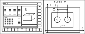
- the trigger event "workpiece coordinate data setting” is "replacement with touch probe”, “display of workpiece coordinate measurement screen”, “selection of hole-to-hole measurement”, “axis operation by jogging", “touch probe contacts workpiece”. ” and “Workpiece coordinate data setting” are linked to an event set consisting of six events.
- the trigger event "workpiece coordinate data setting" in FIG. 12 is the same trigger event as the work unit "workpiece measurement (end face)" in FIG. 11. That is, multiple event sets may correspond to one trigger event. In such a case, searching for events starting from the trigger event and going back in time will eventually converge on one event set (work unit).
- FIG. 11 A specific example is shown in FIG.
- FIG. 14 shows the relationship between work units and viewpoints.
- start machining operation (machining center)
- the Z-axis is set vertically, and the viewpoint is determined so that the workpiece and tool are viewed from the side.
- workpiece measurement end face
- the Z-axis is set vertically, and the viewpoint is determined so that the workpiece and tool are viewed from the side.
- workpiece measurement hole-to-hole measurement
- the Z-axis is set vertically and the viewpoint is determined to be viewed from above.
- a viewpoint can be defined in terms of direction and distance to an object.
- the viewpoint may be selected from predefined directions and distances from the tool and workpiece.
- the viewpoint may be automatically determined by calculating the direction and distance from the target object by using a simulation to avoid obstacles.
- a video seek bar By arranging the work units on the time axis, a video seek bar can be created as shown in FIG. 15. By creating a seek bar, you can check the overall work flow and improve data visibility.
- FIG. 16 is an example in which the image on the display screen of the numerical control device and the image generated by the image generation section 2 are displayed side by side.
- the video generation device 100 merges the video on the display screen of the numerical control device and the generated video based on time, and generates a video in which the two images synchronized by time are combined into one video.
- the image on the display screen of the numerical control device and the image generated by the image generation section 2 are displayed side by side.
- the image on the display screen may be captured instead of being captured by a camera.
- FIG. 17 is a hardware configuration diagram of the video generation device 100.
- the video generation device 100 includes a CPU 111 that controls the entire video generation device 100, a ROM 112 that records programs and data, and a RAM 113 that temporarily expands data.
- a system program recorded in the ROM 112 is read out through the ROM 112, and the entire video generation apparatus 100 is controlled in accordance with the system program.
- the nonvolatile memory 114 is backed up by, for example, a battery (not shown), so that its storage state is maintained even when the power of the video generation device 100 is turned off.
- the nonvolatile memory 114 stores various data such as programs read from external devices via the interfaces 115, 118, and 119 and user operations input via the input unit 71.
- the interface 115 mediates the connection between the video generation device 100 and an external device such as an adapter. Programs and various parameters are read from the external device.
- Video generation device 1 Data acquisition unit 2 Video generation unit 3 Viewpoint determination unit 7 Data history storage unit 8 Event set storage unit 111 CPU 113 RAM 114 Non-volatile memory
Landscapes
- Engineering & Computer Science (AREA)
- Physics & Mathematics (AREA)
- Optics & Photonics (AREA)
- Mechanical Engineering (AREA)
- General Physics & Mathematics (AREA)
- Automation & Control Theory (AREA)
- Numerical Control (AREA)
- Multimedia (AREA)
- Signal Processing (AREA)
Abstract
Description
また、機械の動作順序を制御するPLC(Programmable Logic Controller)や工作機械を制御する数値制御装置(Numerical Control)も内部に記録部を備えており、制御情報や状態情報を記憶している。
本開示の一態様である記憶媒体は、1つ又は複数のプロセッサが実行することにより、産業機械の状態を示すデータを取得し、産業機械の状態を示すデータを検索し、産業機械で実行された作業を示すトリガイベントを検出し、トリガイベントに対応する視点を決定し、視点の決定に基づいた映像を生成する、プロセッサが読み取り可能な命令を記憶する。
また、映像生成装置100は、数値制御装置、PLC(Programmable Logic Controller)などの情報処理装置に適用してもよい。
図2は、第1の開示の映像生成装置100のブロック図である。映像生成装置100は、データ取得部1、映像生成部2、視点決定部3備える。
本開示では、数値制御装置及び工作機械を産業機械の例とする。産業機械の状態情報としては、数値制御装置のモード、工具オフセット量、アラーム、時刻、加工部品数、モーダル情報、位置情報(座標系)、工作機械の電力消費量、サーボモータの負荷、センサで計測したデータ(温度や圧力)などがある。操作入力情報とは、タッチパネル、ボタン、ダイヤル、ハンドルなどへのオペレータからの操作入力である。
図4は、第2の開示の映像生成装置100のブロック図である。映像生成装置100は、データ取得部1、映像生成部2、データ履歴記憶部7、視点決定部3、イベントセット記憶部8を備える。
図5は、視点決定部3の概念モデルである。視点決定部3は、データ取得部1が取得したデータを検索し、トリガイベントを検出する。視点決定部3は、検出したトリガイベントに対応するイベントセットを読み出し、データ履歴記憶部7に記憶された過去のデータを検索して、検出したトリガイベントに対応するイベントセットが過去に発現したか否かを検索する。検出したトリガイベントに対応するイベントセットが過去に発現した場合、ある作業が実行されたと判断する。
イベントセットは、作業の開始から終了までの作業単位に対応する。本開示では、作業の開始時に発現するイベントを開始イベントと呼ぶ。開始イベントからトリガイベントまでが1つの作業単位となる。イベントセットの具体例については後述する。
なお、映像生成部2が生成した映像に、イベントの発現した時刻を付加してもよい。この時刻は、後述するシークバーの作成や他の映像とのマージに用いることができる。
以下、第2の開示の映像生成装置100の具体例を説明する。この例では、イベントをオペレータの操作信号と画面表示に限定して説明する。
前提として、視点決定部3は、データ取得部1が取得したデータからトリガイベントを検索しているものとする。
視点決定部3は、トリガイベント「サイクルスタートボタンの押下」を検出したものとする。図6は、イベントセットの一例である。図6において、トリガイベント「サイクルスタートのボタンの押下」は、「NCモードをMEMに変更するボタンの押下」、「自動運転画面を表示」、「サイクルスタートボタンの押下」という3つのイベントからなるイベントセットに紐づけられている。
なお、上述の説明では、イベントの発現順序を固定したが、順不同にしてもよい。
加工開始前の作業では、ワークと工具の距離を視認しやすい映像が有用である。
図7は、旋盤の例を示す。
旋盤は通常、主軸の回転軸に対し平行な方向がZ軸、Z軸を中指として右手直交座標系で親指の方向をX軸とする。切削開始前の工具とワークの距離を確認するには、XZ平面に垂直な視点がよい。
図8は、XZ平面に垂直な視点で生成した映像である。視点を切り替えることで、ワークと工具の距離が視認しやすい。なお、図8の映像は、視点決定部3の結果に基づく2次元画像である。
マシニングセンタも同様に、工具は、早送りで切削開始位置まで移動し「一時停止」もしくは「減速」する。本例において切削を開始した工具は、ワーク座標系のX軸と並行に移動する。この例では、XZ平面に垂直な視点にすると、工具とワークの距離を確認しやすい。
図10は、XZ平面に垂直な視点で生成した映像である。視点を切り替えることで、ワークと工具の距離が視認しやすい。なお、図10の映像は、視点決定部3の結果に基づく2次元画像である。
視点決定部3は、加工プログラムを解析し、工具の移動方向を基に視点を決定してもよい。
視点決定部3は、データ取得部1が取得したデータを検索して、イベントセットの発現を示すデータを検出する。
図12は、ワーク計測(穴間計測)のトリガイベント及びイベントセットを示す図である。図12におけるトリガイベントは、「ワーク座標のデータ設定」である。トリガイベント「ワーク座標のデータ設定」は、「タッチプローブへの交換」、「ワーク座標計測画面の表示」、「穴間計測の選択」、「ジョグによる軸操作」、「タッチプローブがワークに接触」、「ワーク座標のデータ設定」という6つのイベントからなるイベントセットと紐づけられている。
視点は、対象物に対する方向及び距離で定義することができる。例えば、予め定義してある工具及びワークから見た方向と距離の中から視点を選択するようにしてよい。また、対象物との間に障害物が入らない方向及び距離をシミュレーションで計算して自動的に視点を決定するようにしてもよい。
第3の開示では、数値制御装置の表示画面の映像と、映像生成部2が生成した映像を並べて表示する。図16は、数値制御装置の表示画面の映像と、映像生成部2が生成した映像とを並べて表示した例である。映像生成装置100は、数値制御装置の表示画面の映像と生成した映像とを時刻でマージし、時刻で同期を取った2つの映像を1つにした映像を生成する。
図16の例では、数値制御装置の表示画面の映像と映像生成部2が生成した映像を並べて表示している。表示画面の映像は、カメラで撮像するのではなく、キャプチャしてもよい。表示画面の映像とシミュレーション映像とを並べることで、オペレータの操作と、産業機械の状態とを同時に確認することができる。
1 データ取得部
2 映像生成部
3 視点決定部
7 データ履歴記憶部
8 イベントセット記憶部
111 CPU
113 RAM
114 不揮発性メモリ
Claims (8)
- 産業機械の機械状態を示すデータを取得するデータ取得部と、
前記産業機械の状態を示すデータを検索し、前記産業機械で実行された作業を示すトリガイベントを検出し、前記トリガイベントに対応する視点を決定する視点決定部と、
前記視点決定部が決定した視点に基づいて、前記産業機械の映像を生成する映像生成部と、
を備える映像生成装置。 - 前記データ取得部が取得したデータの履歴を記憶するデータ履歴記憶部を備え、
前記視点決定部は、複数のイベントの組み合わせであるイベントセットを記憶し、前記トリガイベントを検出した場合、前記イベントセットに含まれるイベントの発現を示すデータが前記データ履歴記憶部に存在するか否かを検索し、前記イベントセットに含まれるイベントの発現を示すデータが前記データ履歴記憶部に存在する場合、前記イベントセットに対応する作業単位を決定し、前記作業単位に対応する視点を決定する、請求項1記載の映像生成装置。 - 前記視点決定部は、前記トリガイベントを起点として、時間をさかのぼりながらイベントセットに含まれるイベントの発現を示すデータの検索を行う、請求項1記載の映像生成装置。
- 前記映像生成部が生成した映像に、前記イベントの発現した時刻を付加する、請求項2記載の映像生成装置。
- 前記イベントセットに含まれるイベントの発現時刻を示すシークバーを作成する、請求項2記載の映像生成装置。
- 前記作業単位の発現時刻を示すシークバーを作成する、請求項2記載の映像生成装置。
- 前記映像取得部は、前記産業機械の動作を示すシミュレーション映像、又は前記視点決定部の結果に基づく2次元映像を生成する映像生成部である、請求項1記載の映像生成装置。
- 1つ又は複数のプロセッサが実行することにより、
産業機械の状態を示すデータを取得し、
前記産業機械の状態を示すデータを検索し、前記産業機械で実行された作業を示すトリガイベントを検出し、前記トリガイベントに対応する視点を決定し、
前記視点の決定に基づいた映像を生成する、
前記プロセッサが読み取り可能な命令を記憶する記憶媒体。
Priority Applications (5)
| Application Number | Priority Date | Filing Date | Title |
|---|---|---|---|
| DE112022006760.8T DE112022006760T5 (de) | 2022-05-13 | 2022-05-13 | Videoerzeugungsvorrichtung und computerlesbares speichermedium |
| CN202280095754.2A CN119137556A (zh) | 2022-05-13 | 2022-05-13 | 影像生成装置以及计算机可读存储介质 |
| JP2024520216A JPWO2023218643A1 (ja) | 2022-05-13 | 2022-05-13 | |
| PCT/JP2022/020231 WO2023218643A1 (ja) | 2022-05-13 | 2022-05-13 | 映像生成装置、及びコンピュータが読み取り可能な記憶媒体 |
| US18/862,930 US20250301206A1 (en) | 2022-05-13 | 2022-05-13 | Video generation device and computer-readable storage medium |
Applications Claiming Priority (1)
| Application Number | Priority Date | Filing Date | Title |
|---|---|---|---|
| PCT/JP2022/020231 WO2023218643A1 (ja) | 2022-05-13 | 2022-05-13 | 映像生成装置、及びコンピュータが読み取り可能な記憶媒体 |
Publications (1)
| Publication Number | Publication Date |
|---|---|
| WO2023218643A1 true WO2023218643A1 (ja) | 2023-11-16 |
Family
ID=88730127
Family Applications (1)
| Application Number | Title | Priority Date | Filing Date |
|---|---|---|---|
| PCT/JP2022/020231 Ceased WO2023218643A1 (ja) | 2022-05-13 | 2022-05-13 | 映像生成装置、及びコンピュータが読み取り可能な記憶媒体 |
Country Status (5)
| Country | Link |
|---|---|
| US (1) | US20250301206A1 (ja) |
| JP (1) | JPWO2023218643A1 (ja) |
| CN (1) | CN119137556A (ja) |
| DE (1) | DE112022006760T5 (ja) |
| WO (1) | WO2023218643A1 (ja) |
Citations (4)
| Publication number | Priority date | Publication date | Assignee | Title |
|---|---|---|---|---|
| JP2010061661A (ja) * | 2008-09-05 | 2010-03-18 | Mori Seiki Co Ltd | 加工状況監視方法及び加工状況監視装置 |
| WO2013058093A1 (ja) * | 2011-10-18 | 2013-04-25 | 日立建機株式会社 | 作業機械の周囲監視装置 |
| JP2020077173A (ja) * | 2018-11-07 | 2020-05-21 | コベルコ建機株式会社 | 建設機械の遠隔操作装置 |
| JP2020175890A (ja) * | 2020-06-30 | 2020-10-29 | 株式会社クボタ | 作業車 |
Family Cites Families (5)
| Publication number | Priority date | Publication date | Assignee | Title |
|---|---|---|---|---|
| JP2001125612A (ja) | 1999-10-25 | 2001-05-11 | Omron Corp | 設備ロギング装置 |
| US20060177119A1 (en) * | 2002-10-25 | 2006-08-10 | Mcpheely Bernard M | Digital diagnosti video system for manufacturing and industrial process |
| US20180205905A1 (en) * | 2017-01-19 | 2018-07-19 | Caterpillar Inc. | Structural health monitoring systems utilizing visual feedback and selective recording |
| JP6969447B2 (ja) | 2018-03-05 | 2021-11-24 | 日本電産株式会社 | ロボット制御装置、記録の作成方法およびプログラム |
| JP7637399B2 (ja) * | 2019-08-26 | 2025-02-28 | 株式会社イシダ | 生産システム |
-
2022
- 2022-05-13 WO PCT/JP2022/020231 patent/WO2023218643A1/ja not_active Ceased
- 2022-05-13 DE DE112022006760.8T patent/DE112022006760T5/de active Pending
- 2022-05-13 US US18/862,930 patent/US20250301206A1/en active Pending
- 2022-05-13 JP JP2024520216A patent/JPWO2023218643A1/ja active Pending
- 2022-05-13 CN CN202280095754.2A patent/CN119137556A/zh active Pending
Patent Citations (4)
| Publication number | Priority date | Publication date | Assignee | Title |
|---|---|---|---|---|
| JP2010061661A (ja) * | 2008-09-05 | 2010-03-18 | Mori Seiki Co Ltd | 加工状況監視方法及び加工状況監視装置 |
| WO2013058093A1 (ja) * | 2011-10-18 | 2013-04-25 | 日立建機株式会社 | 作業機械の周囲監視装置 |
| JP2020077173A (ja) * | 2018-11-07 | 2020-05-21 | コベルコ建機株式会社 | 建設機械の遠隔操作装置 |
| JP2020175890A (ja) * | 2020-06-30 | 2020-10-29 | 株式会社クボタ | 作業車 |
Also Published As
| Publication number | Publication date |
|---|---|
| US20250301206A1 (en) | 2025-09-25 |
| DE112022006760T5 (de) | 2025-01-23 |
| JPWO2023218643A1 (ja) | 2023-11-16 |
| CN119137556A (zh) | 2024-12-13 |
Similar Documents
| Publication | Publication Date | Title |
|---|---|---|
| JP5337636B2 (ja) | 加工状況監視方法及び加工状況監視装置 | |
| CN101957610B (zh) | 机床的刀具轨迹显示装置 | |
| JP5536611B2 (ja) | 工作機械のモニタ方法及びモニタ装置、工作機械 | |
| JP6445070B2 (ja) | 工作機械の制御システム | |
| CA2784720C (en) | Predictive control and visualizing system for a nc machine tool | |
| JP5608036B2 (ja) | 稼動履歴管理方法、及び稼動履歴管理装置 | |
| US9665085B2 (en) | Cutting condition and tool life display device for a numerical controller | |
| JP6570592B2 (ja) | 工作機械の機上測定方法および制御装置 | |
| US11947332B2 (en) | CAD data-based automatic operation device of machining center | |
| CN106181581A (zh) | 机床的振动信息显示装置 | |
| JP6496338B2 (ja) | 工作機械の制御システム | |
| JP6514264B2 (ja) | 工作機械の制御システム | |
| JP2019117477A (ja) | リンク情報生成装置、リンク情報生成方法及びリンク情報生成プログラム | |
| JP2016031643A (ja) | 機械異常履歴の解析支援機能を有する数値制御装置 | |
| JP2006085328A (ja) | 工作機械制御装置 | |
| JP2006085328A5 (ja) | ||
| CN113031521A (zh) | 数控机床的刀具监控系统和方法 | |
| JP6913058B2 (ja) | 加工シミュレーション装置 | |
| JP7167607B2 (ja) | 工作機械 | |
| US20250301206A1 (en) | Video generation device and computer-readable storage medium | |
| JP2020055043A (ja) | 工作機械 | |
| WO2023218651A1 (ja) | 映像関連情報決定装置、及びコンピュータが読み取り可能な記憶媒体 | |
| JP7827845B2 (ja) | 映像生成装置、及びコンピュータが読み取り可能な記憶媒体 | |
| JP2008234131A (ja) | 工作機械における監視システム | |
| WO2022244070A1 (ja) | 稼働状況表示装置、およびコンピュータ読み取り可能な記憶媒体 |
Legal Events
| Date | Code | Title | Description |
|---|---|---|---|
| 121 | Ep: the epo has been informed by wipo that ep was designated in this application |
Ref document number: 22941720 Country of ref document: EP Kind code of ref document: A1 |
|
| ENP | Entry into the national phase |
Ref document number: 2024520216 Country of ref document: JP Kind code of ref document: A |
|
| WWE | Wipo information: entry into national phase |
Ref document number: 112022006760 Country of ref document: DE |
|
| WWE | Wipo information: entry into national phase |
Ref document number: 18862930 Country of ref document: US |
|
| WWE | Wipo information: entry into national phase |
Ref document number: 202280095754.2 Country of ref document: CN |
|
| 122 | Ep: pct application non-entry in european phase |
Ref document number: 22941720 Country of ref document: EP Kind code of ref document: A1 |
|
| WWP | Wipo information: published in national office |
Ref document number: 18862930 Country of ref document: US |