WO2023218632A1 - レーダ装置および物標検知方法 - Google Patents
レーダ装置および物標検知方法 Download PDFInfo
- Publication number
- WO2023218632A1 WO2023218632A1 PCT/JP2022/020185 JP2022020185W WO2023218632A1 WO 2023218632 A1 WO2023218632 A1 WO 2023218632A1 JP 2022020185 W JP2022020185 W JP 2022020185W WO 2023218632 A1 WO2023218632 A1 WO 2023218632A1
- Authority
- WO
- WIPO (PCT)
- Prior art keywords
- axis
- axis direction
- radar device
- peak value
- antenna
- Prior art date
- Legal status (The legal status is an assumption and is not a legal conclusion. Google has not performed a legal analysis and makes no representation as to the accuracy of the status listed.)
- Ceased
Links
Images


Classifications
-
- G—PHYSICS
- G01—MEASURING; TESTING
- G01S—RADIO DIRECTION-FINDING; RADIO NAVIGATION; DETERMINING DISTANCE OR VELOCITY BY USE OF RADIO WAVES; LOCATING OR PRESENCE-DETECTING BY USE OF THE REFLECTION OR RERADIATION OF RADIO WAVES; ANALOGOUS ARRANGEMENTS USING OTHER WAVES
- G01S7/00—Details of systems according to groups G01S13/00, G01S15/00, G01S17/00
- G01S7/02—Details of systems according to groups G01S13/00, G01S15/00, G01S17/00 of systems according to group G01S13/00
Definitions
- the present invention relates to a radar device and a target object detection method.
- a millimeter wave radar mounted on a vehicle or the like can determine the distance, speed, and angle of a target by receiving the reflected waves of transmitted waves reflected by the target.
- Millimeter wave radar can calculate the horizontal angle if multiple receiving antennas are arranged horizontally, and can calculate the height of a target if multiple receiving antennas are arranged vertically (e.g. , see Patent Document 1).
- There is also a method of determining the horizontal angle and vertical angle by arranging a plurality of receiving antennas in a plane to generate a two-dimensional spectrum for example, see Patent Document 2.
- the present invention has been made in consideration of the above points, and an object of the present invention is to accurately detect a target while suppressing the amount of calculation.
- one aspect of the present invention provides a radar device that estimates the direction of arrival of a received signal in which a reflected wave of a transmitted signal reflected by a target object is received via a plurality of antennas, a signal processing unit that processes a received signal to estimate the direction of arrival;
- the plurality of antennas are two-dimensionally arranged in a coordinate system having a first axis and a second axis as coordinate axes; , calculate a steering vector of the antenna in the first axis direction based on the received signal, and scan an angle in the first axis direction at a first spectral intensity of the received signal based on the steering vector to obtain a first steering vector.
- a first axis direction estimating unit that calculates a peak value of and performs processing for estimating the direction of arrival regarding the first axis based on the first peak value; and a first axis direction estimation unit that calculates a peak value of to calculate a steering vector of the antenna in the second axis direction, and calculate a second peak value by scanning an angle in the second axis direction at a second spectral intensity of the received signal based on the steering vector.
- a second axis direction estimator that performs a process of estimating the direction of arrival regarding the second axis based on the second peak value.
- target detection can be performed with high accuracy while suppressing the amount of calculation.
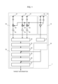
- FIG. 1 is a diagram showing the configuration of a radar device according to a first embodiment
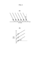
- FIG. FIG. 3 is a diagram showing the angle of the reflected wave from the target with respect to the first axis and the angle of the reflected wave from the target with respect to the second axis according to the first embodiment.
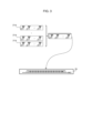
- FIG. 6 is a diagram showing how to use two-dimensionally arranged receiving antennas in a second axis spatial averaging processing section and a first axis direction estimating section. It is a figure which shows the process in a scanning range limitation process part and a 2nd axis direction estimation part. It is a flowchart which shows the flow of processing from the second axis spatial averaging processing section to the second axis direction estimating section of the signal processing section.
- FIG. 3 is a diagram showing an example of antenna arrangement according to the first embodiment. It is a figure which shows an example of the calculation result of the one-dimensional angular spectrum intensity of a 1st axis direction. It is a figure which shows an example of the calculation result of the two-dimensional angular spectrum intensity of a 2nd axis direction. 7 is a diagram showing an example of antenna arrangement according to Embodiment 2.
- FIG. 3 is a diagram showing an example of antenna arrangement according to the first embodiment. It is a figure which shows an example of the calculation result of the one-dimensional angular spectrum intensity of a 1st axis direction. It is a figure which shows an example of the calculation result of the two-dimensional angular spectrum intensity of a 2nd axis direction.
- 7 is a diagram showing an example of antenna arrangement according to Embodiment 2.
- a computer executes a program using a processor (for example, a CPU (Central Processing Unit), a GPU (Graphics Processing Unit)), and performs processing determined by the program while using storage resources (for example, a memory). Therefore, the main body of processing performed by executing a program may be a processor.
- the main body of the processing performed by executing the program may be an arithmetic unit, and may include a dedicated circuit that performs specific processing.
- the dedicated circuit is, for example, an FPGA (Field Programmable Gate Array), an ASIC (Application Specific Integrated Circuit), or a CPLD (Complex Programmable Logic Device).
- FIG. 1 is a diagram showing the configuration of a radar device 1 according to the first embodiment.
- the radar device 1 is mounted, for example, on a vehicle such as a railroad or a car.
- the radar device 1 is used to detect targets existing around or in front of the vehicle.
- the radar device 1 acquires target data by transmitting a transmitted wave that is reflected by a target object and receiving a reflected wave that returns to the radar device 1 .
- the data on the target includes the distance to the target, the relative speed of the target with respect to the radar device 1, the direction in which the target exists, and the like.
- the radar device 1 includes a transmitting section 10, a receiving section 20, a signal processing section 30, and a memory section 40.
- the transmitter 10 includes an oscillator 11 and a transmitting antenna 12.
- distance and speed information are calculated based on the results of transmitting and receiving a chirp signal whose frequency changes linearly depending on time, which is generally referred to as the FMCW (Frequency Modulated Continuous Wave) method.
- the oscillator 11 receives information about a signal to be transmitted from the signal control section 31 in the signal processing section 30 and generates a chirp signal.
- the generated chirp signal is transmitted as a transmission wave from the transmission antenna 12.
- the transmitted wave is reflected by a target object such as another vehicle, and becomes a reflected wave.
- the receiving unit 20 includes a plurality of receiving antennas 21, a mixer 22 connected to each receiving antenna 21, and an A/D (Analog to Digital) converter 23.
- a part of the reflected wave reflected by the target object is received by the receiving antenna 21.
- the received signal that has received the reflected wave is input to the mixer 22 .
- the mixer 22 generates a beat signal by mixing the received signal and the transmitted signal (oscillation signal of the oscillator 11).
- the beat signal is converted into a digital signal by the A/D converter 23 and output to the signal processing section 30.
- the beat signal after A/D conversion is used to perform Fourier transform, distance/velocity calculation, first axis direction estimation, and second axis direction estimation.
- the memory section 40 stores information necessary for the signal processing section 30, such as antenna coordinate information and information on modulation settings of the transmission signal.
- the antenna coordinate information is, for example, the distance d1 in the first axis direction and the distance d2 in the second axis direction of the two-dimensionally arranged receiving antennas 21 (described later with reference to FIG. 6). Further, the antenna coordinate information includes offset values d12, d13, . . . of other receiving antenna subarrays with respect to the receiving antenna subarray that is a reference for the receiving antenna 21 in the first axis direction. Similarly, the antenna coordinate information includes offset values d22, d23, . . . of other columns with respect to the reference column of the receiving antenna 21 in the second axis direction (described later with reference to FIG. 9).
- the signal transmitted from the transmitting antenna 12 is received by the receiving antenna 21 through a route that is twice the distance to the target object.
- a delay time occurs between the time when a signal whose frequency changes depending on the time of day is transmitted and when it is reflected by a target object and reaches the receiving antenna 21, resulting in a frequency difference between the transmitted signal and the received signal. occurs.
- the longer the distance to the target the greater the delay time and the greater the frequency difference between the transmitted and received signals.
- the beat signal after A/D conversion is Fourier transformed in the time direction, thereby determining the distance to the target based on the frequency difference.
- the Fourier transform unit 32 performs two-dimensional FFT (Fast Fourier Transform) on the received signal input to the signal processing unit 30 as described above.
- a power spectrum of distance and velocity is obtained by FFT processing.
- the distance/velocity calculation unit 33 searches for a peak bin that is equal to or greater than a threshold value from the power spectrum of the distance/velocity obtained by the Fourier transform unit 32, thereby determining the distance and velocity of the detected target.
- the Fourier transform unit 32 Since the Fourier transform unit 32 performs FFT processing on the signals received by each receiving antenna 21, it obtains the same number of distance and velocity spectra as the number of channels of the receiving antenna 21. Here, the obtained peak bin is the same for all receiving antennas 21, but the complex information of the amplitude and phase of the frequency spectrum at the peak bin differs for each receiving antenna 21. Since the way in which the complex information differs for each receiving antenna 21 is determined by the antenna arrangement and the target object direction, the direction of the target object is determined from the complex information obtained from each receiving antenna 21 and the antenna arrangement.
- the received signal refers to the complex signal at the peak bin of the distance and velocity spectra.
- the processing after the second axis spatial averaging processing unit 34 is the processing for determining the direction of the target object.
- FIG. 2 is a diagram showing the angle of the reflected wave from the target with respect to the first axis and the angle of the reflected wave from the target with respect to the second axis according to the first embodiment.
- the receiving antenna has a two-dimensional arrangement with the first axis and the second axis, and the angle ⁇ of the target with respect to the first axis is defined as shown in FIG.
- the angle ⁇ of the target object is defined as shown in FIG. 2(b).
- the first axis is the horizontal direction and the second axis is the vertical direction, but the invention is not limited thereto.
- FIG. 3 is a diagram showing how to use the two-dimensionally arranged receiving antenna 21 in the second axis spatial averaging processing section and the first axis direction estimation section.
- the second axis spatial averaging processing unit 34 performs processing for using the two-dimensionally arranged receiving antennas 21 as one-dimensional antennas. Specifically, the received signals obtained by the two-dimensionally arranged receiving antennas 21 are grouped into each receiving antenna array 21A having the same second axis coordinates, the correlation matrix R of the received signals of each group is determined, and the correlation matrix R of the received signals of each group is calculated. Performs averaging processing of the correlation matrix. Details will be described later.
- the correlation matrix R of the received signal obtained here is regarded as the correlation matrix of the received signal by the one-dimensional antenna array parallel to the first axis.
- the first axis direction estimation unit 35 uses the correlation matrix R obtained by the second axis spatial averaging processing unit 34 and the antenna coordinates regarded as one-dimensional to estimate the one-dimensional angular spectrum intensity P1( ⁇ ) regarding the angle ⁇ . Do calculations. Then, the first axis direction estimating unit 35 estimates the angle ⁇ indicating the direction in which the target exists with respect to the first axis by determining the angle ⁇ at which the one-dimensional angular spectrum intensity P1( ⁇ ) is equal to or greater than the threshold value. For example, when the first axis is in the horizontal direction, the calculation is to find the horizontal angle.
- the direction is estimated using a known method such as Capon or MUSIC (Multiple Signal Classification).
- FIG. 4 is a diagram showing processing in the scanning range limitation processing section 36 and the second axis direction estimation section 37.
- the scanning range limitation processing unit 36 determines the angular range of the first axis in which two-dimensional direction estimation is performed based on the result of the first axis direction estimation unit 35.
- the angular range of the first axis in which the two-dimensional direction estimation is performed is a predetermined range that includes the angle ⁇ at which the one-dimensional angular spectrum intensity P1( ⁇ ) is equal to or greater than the threshold value in the first axial direction estimator 35.
- the second axis direction estimating unit 37 limits the range of the angle ⁇ determined by the scanning range limiting processing unit 36, calculates the two-dimensional angle spectrum intensity P2 ( ⁇ , ⁇ ) regarding the angle ⁇ , and calculates the two-dimensional angle
- a second axis direction estimation is performed to obtain an angle ⁇ at which the spectral intensity P2( ⁇ , ⁇ ) is equal to or greater than a threshold value.
- the second axis spatial averaging processing section 34 the first axis direction estimation section 35, the scanning range limitation processing section 36, and the second axis direction estimation section 37 will be explained.
- the antenna arrangement will be explained.
- FIG. 6 is a diagram showing an example of antenna arrangement according to the first embodiment.
- the reception antenna array is composed of 18 elements of reception antennas Rx1 to Rx18 arranged in a grid with six columns in the first axis direction and three columns in the second axis direction.
- G1 be the receiving antenna subarray of Rx1 to Rx6,
- G2 be the receiving antenna subarray of Rx7 to Rx12,
- G3 be the receiving antenna subarray of Rx13 to Rx18.
- d1 be the interval between the six receiving antenna elements arranged parallel to the first axis in the receiving antenna subarrays G1, G2, G3, and the second axis coordinate difference ( interval) is set as d2.
- a plurality of antennas arranged in a grid are divided by a plurality of parallel lines, a plurality of reception antenna subarrays G1, G2, and G3 are arranged in the second axis direction and are located at the same distance from the second axis. This is an example of a linear antenna subarray including the same number of elements.
- the receiving antennas Rx1 to Rx18 may be virtual antennas obtained by MIMO (Multiple-Input and Multiple-Output) or other extended signal processing.
- MIMO Multiple-Input and Multiple-Output
- a virtual received signal at the virtual antenna may be generated before the second axis spatial averaging process.
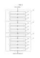
- FIG. 5 is a flowchart showing the flow of processing from the second axis spatial averaging processing unit 34 to the second axis direction estimation unit 37 of the signal processing unit 30.
- the second axis spatial averaging processing unit 34 groups antenna arrays having the same second axis coordinates as subarrays (one-dimensional antenna subarray generation process).
- G1 be the receiving antenna subarray of Rx1 to Rx6,
- G2 be the receiving antenna subarray of Rx7 to Rx12, and
- G3 be the receiving antenna subarray of Rx13 to Rx18.
- the received signals obtained by each receiving antenna Rx1 to Rx18 are assumed to be s1 to s18.
- step S2 the second axis spatial averaging processing unit 34 uses the received signals s(1), s(2), and s(3) obtained from each receiving antenna subarray to create correlation matrices R1, R2, Calculate R3 (subarray correlation matrix calculation process).
- step S3 the second axis spatial averaging processing unit 34 calculates three correlation matrices R1, R2 calculated from the received signals s(1), s(2), s(3) of each receiving antenna sub-array. , R3 is generated (correlation matrix averaging process).
- the first axial direction estimation unit 35 calculates the one-dimensional angular spectrum intensity necessary for first axial direction estimation.
- a one-dimensional steering vector is required when two-dimensionally arranged antennas are used as one-dimensional antennas.
- the first axis direction estimation unit 35 generates a one-dimensional steering vector a1 ( ⁇ ) based on the antenna coordinate information (first axis one-dimensional steering vector generation process).
- the one-dimensional steering vector a1( ⁇ ) is expressed as in equation (1) using the coordinates of the receiving antenna along the first axis.
- ⁇ indicates wavelength.
- ⁇ is a value that changes depending on the direction of the desired spectrum.
- step S5 the first axis direction estimation unit 35 uses the matrix Rmean obtained in step S3 and the one-dimensional steering vector a1( ⁇ ) generated in step S4 to determine the one-dimensional angular spectrum intensity in the first axis direction.
- P1( ⁇ ) is calculated (first axis one-dimensional direction spectrum calculation process).
- a method for calculating the one-dimensional angular spectrum intensity P1( ⁇ ) is expressed as in equation (2) when using the Capon method, for example.
- the one-dimensional angular spectrum intensity P1( ⁇ ) in the first axis direction is calculated by scanning the angle ⁇ in a predetermined range predetermined from the viewing angle of the antenna.
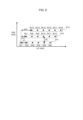
- FIG. 7 shows an example of the one-dimensional angular spectrum intensity P1( ⁇ ) obtained when two targets with different first axis directions exist in the same distance/velocity bin.
- Calculation of the one-dimensional angular spectrum intensity P1 ( ⁇ ) is not limited to Capon, and for example, DBF (Digital Beamforming), MUSIC, or the like may be used.
- step S6 the first axial direction estimation unit 35 extracts the angle ⁇ when the one-dimensional angular spectrum intensity P1( ⁇ ) exceeds a predetermined threshold (first axial direction peak extraction process).
- a predetermined threshold first axial direction peak extraction process
- the scanning range limitation processing unit 36 receives the first axis peak angles ⁇ 1 and ⁇ 2 extracted by the first axis direction estimation unit 35, and calculates the two-dimensional angle by the next second axis direction estimation unit 37.
- the calculation range of the angular spectrum intensity P2 ( ⁇ , ⁇ ) is determined and listed. For example, in the case of 1 degree increments within the ⁇ 1 degree range of each of ⁇ 1 and ⁇ 2, the second axis direction estimating unit 37 inputs ( ⁇ 1-1, ⁇ 1, ⁇ 1+1) and ( ⁇ 2-1, ⁇ 2, ⁇ 2+1) to ⁇ . Output as the scan range. For example, this list may include only ⁇ 1 and ⁇ 2.
- the second axis direction estimation list only contains ⁇ 1 and ⁇ 2. However, sufficient accuracy can be obtained.
- the second axis direction estimation unit 37 calculates the two-dimensional angular spectrum intensity P2 ( ⁇ , ⁇ ) necessary for second axis direction estimation.
- the second axis direction estimation unit 37 generates an 18 ⁇ 18 correlation matrix R using the received signals s1 to s18 of the two-dimensionally arranged receiving antennas (full antenna array correlation matrix calculation process). .
- a two-dimensional steering vector of the two-dimensionally arranged receiving antenna 21 is required.
- the second axis direction estimation unit 37 generates a two-dimensional steering vector a2 ( ⁇ , ⁇ ) based on the antenna coordinate information (second axis two-dimensional steering vector calculation process).
- the two-dimensional steering vector a2 ( ⁇ , ⁇ ) is expressed as in equation (3).
- ⁇ is changed by a value in a list determined by the scanning range limiting processing unit 36, and first, it is changed by a value in a list including ⁇ 1.
- the second axis direction estimating unit 37 calculates a two-dimensional angular spectrum intensity P2 for ⁇ determined by the scanning range limiting processing unit 36 and ⁇ in a predetermined range determined in advance from the viewing angle of the antenna. ( ⁇ , ⁇ ) (two-dimensional directional spectrum calculation process within a predetermined range).
- the two-dimensional angular spectrum intensity P2 ( ⁇ , ⁇ ) is calculated as shown in equation (4) using the two-dimensional steering vector a2 ( ⁇ , ⁇ ) and the correlation matrix R.
- step S11 the second axis direction estimation unit 37 extracts ⁇ and ⁇ when the two-dimensional angular spectrum intensity P2 ( ⁇ , ⁇ ) is equal to or greater than a predetermined threshold (direction peak extraction process within a predetermined range). .
- the second axis direction estimation unit 37 similarly performs the processing of steps S9 to S11 for the list including ⁇ 2.
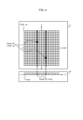
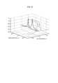
- FIG. 8 is a diagram showing an example of the calculation result of the two-dimensional angular spectrum intensity P2 ( ⁇ , ⁇ ) in the second axis direction.
- FIG. 8 shows an example of the two-dimensional angular spectrum intensity P2 ( ⁇ , ⁇ ) obtained when there are two targets with the same distance and speed bin that are different in both the first and second axis directions. .
- steps S1 to S11 are repeated for each distance/velocity bin.
- the receiving antenna 21 has a rectangular arrangement consisting of 18 elements in total, 6 elements in the first axis direction and 3 elements in the second axis direction, but they are arranged in the first axis direction and the second axis direction.
- the combination of the number of antenna elements is not limited to this.
- the number of targets to be detected is not limited to this.
- the receiving antennas are grouped into antenna arrays parallel to the first axis that are two-dimensionally arranged in a coordinate system having the first axis and the second axis as the coordinate axes. Then, a peak angle in the first axis direction at which the spectrum intensity of the received signal in the first axis direction reaches a peak value is calculated. Then, calculation of the peak angle in the second axis direction at which the spectrum intensity of the received signal in the second axis direction has a peak value is performed within a limited range based on the peak angle in the first axis direction.
- the direction of arrival of the reflected wave of the transmitted signal reflected by the target object that is, the angle of the position of the target object with respect to the two axes, can be determined with high precision while suppressing the amount of calculation. Further, it is possible to achieve high resolution in millimeter wave radar.
- the received signals are grouped for each antenna subarray, the received signals received through different antennas in the second axis direction are averaged, and the first Calculate the axial steering vector. Therefore, according to the present embodiment, it is possible to calculate a steering vector in the first axis direction based on the received signals of a plurality of receiving antennas having different coordinates of the second axis.
- the number of elements lined up in the first axis direction is greater than or equal to the number of elements lined up in the second axis direction. If the number of elements aligned in the first axis direction is sufficiently larger than the number of elements aligned in the second axis direction, when calculating the peak value of the two-dimensional angular spectrum intensity P2 ( ⁇ , ⁇ ), the angle ⁇ in the first axis direction The scanning range can be made smaller. Furthermore, only the angle ⁇ that gives the peak value of the one-dimensional angular spectrum intensity P1( ⁇ ) can be used. Therefore, the amount of calculation can be suppressed.
- multiple antennas can be configured using virtual antennas.
- the receiving antenna is composed of a group of six antenna subarrays.
- the correlation matrix of the received signal obtained here is regarded as the correlation matrix of the received signal by the one-dimensional antenna array parallel to the second axis.
- the angle ⁇ indicating the direction in which the target exists with respect to the second axis is estimated using the correlation matrix after the averaging process and the antenna coordinates that are regarded as a one-dimensional array in the second axis direction.
- an angular range of the second axis is determined for which the direction regarding the first direction is estimated using the two-dimensional steering vector.
- the direction of the target object with respect to the first axis is estimated within the angle range of the second axis for which direction estimation is performed, and the angle of the target object with respect to the first axis and the angle with respect to the second axis are determined.
- the first axis and the second axis are exchanged, and the first axis after the exchange is A process for estimating the direction of arrival regarding the axis and a process for estimating the direction of arrival regarding the second axis are performed. Therefore, by checking whether the estimated values of the angle in the first axis direction and the second axis direction match before and after the first axis and the second axis are exchanged, it is possible to guarantee the angle estimation accuracy while suppressing the amount of calculation.
- Embodiment 2 In the antenna arrangement example of Embodiment 1 shown in FIG. 6, there are antenna arrays parallel to the first axis and antenna arrays parallel to the second axis, but antennas with different coordinates in the second axis direction are parallel to the second axis. They do not have to be parallel. In this embodiment, an antenna arrangement different from the antenna arrangement example of Embodiment 1 will be described.
- FIG. 9 is a diagram showing an example of antenna arrangement according to the second embodiment.
- the reception antenna array is composed of 18 elements of reception antennas Rx1 to Rx18 arranged in a grid with six rows in the first axis direction and three rows in the second axis direction.
- the receiving antenna sub-array of Rx1 to Rx6 is G11
- the receiving antenna sub-array of Rx7 to Rx12 is G12
- the receiving antenna sub-array of Rx13 to Rx18 is G13.
- the interval between the six receiving antenna elements arranged parallel to the first axis is d1
- the second axis coordinate difference (interval) of the antenna subarrays having different second axis coordinates is d2.
- d12 be the difference (offset value) in the first axis coordinates between the receiving antenna subarray G11 and the receiving antenna subarray G12
- d13 be the difference (offset value) in the first axis coordinates between the receiving antenna subarray G12 and the receiving antenna subarray G13.
- a plurality of reception antenna subarrays G11, G12, and G13 are arranged in the second axis direction when a plurality of antennas arranged in a grid are divided by a plurality of parallel lines, and each one is arranged at a different distance from the second axis.
- 1 is an example of a linear antenna subarray containing the same number of elements located in a row.
- the antenna arrangement is different from the first embodiment.
- the two-axis spatial averaging process steps S1 to S3
- the two-dimensional direction estimation process steps S4 to S6
- the scanning range limiting process step S7
- the entire antenna array correlation matrix calculation process step S8
- a plurality of antennas arranged in a grid are divided by a plurality of parallel lines, and it is assumed that a plurality of linear antenna sub-arrays including the same number of elements are arranged in the second axis direction.
- the plurality of antenna subarrays are each located at a different distance from the second axis. Therefore, the receiving antenna can be arranged flexibly.
- the radar device can be mounted on vehicles in various forms.
- the first axis is horizontal and the second axis is vertical. If a target is detected and the first axis direction is estimated, and it is estimated that there is a target in the direction of travel of the vehicle, etc. to which the radar device 1 is attached, it is determined whether the target is in front of the collision. It is important to judge whether it is at the top where it will not collide. Since the second axis direction estimation in this case is important, it is necessary to obtain it more accurately.
- the second axis direction estimation may be less accurate than the case where detection is performed in the traveling direction. For this reason, the scanning interval of the angle in the two-dimensional angle spectrum intensity calculation of the second axis may be increased or the scanning range may be narrowed.
- the detected target is in front of the collision, or in a location other than the front, such as on the top of the vehicle, where it will not collide. You can judge.
- the first axis direction estimation if it is determined that the target object is located outside the course where it will not collide, such as at the top of a curve or tunnel, two-dimensional angular spectrum intensity calculation is performed when estimating the second axis direction. Increase the angular scanning interval or narrow the scanning range.
- the first axis direction estimator 35 calculates the peak value of the one-dimensional angular spectrum intensity P1( ⁇ ) according to the result of the spatial Fourier transform between the receiving antennas.
- the scanning range and/or scanning interval of the uniaxial angle ⁇ may be determined.
- the received signal is subjected to spatial Fourier transform between multiple antennas, and the angular scanning range or scanning interval in the first axis direction when calculating the first peak value is calculated using the spatial Fourier transform result.
- the direction of the target can be determined efficiently by changing the direction according to the .
- inter-receiving antenna spatial Fourier transform may be processed as a three-dimensional Fourier transform together with the two-dimensional Fourier transform for determining distance and velocity in the Fourier transform unit 32.
- the area where highly accurate target detection is required is identified in advance, and the spectrum is calculated at fine angles within this specific area to perform highly accurate target detection, while reducing the detection accuracy outside the specific area. This allows highly accurate target detection without increasing the calculation load.
- the present invention is not limited to the above-described embodiments, but includes various modifications.
- the above-described embodiments have been described in detail to explain the present invention in an easy-to-understand manner, and the present invention is not necessarily limited to having all the configurations described.
- combinations of embodiments and modifications such as replacing part of the configuration of one embodiment with the configuration of another embodiment or adding the configuration of another embodiment to the configuration of one embodiment are also possible as long as there is no contradiction. be.
- the configurations and processes shown in the embodiments can be distributed, integrated, or replaced as appropriate based on processing efficiency or implementation efficiency.
Landscapes
- Engineering & Computer Science (AREA)
- Computer Networks & Wireless Communication (AREA)
- Physics & Mathematics (AREA)
- General Physics & Mathematics (AREA)
- Radar, Positioning & Navigation (AREA)
- Remote Sensing (AREA)
- Radar Systems Or Details Thereof (AREA)
Abstract
レーダ装置(1)は、第1軸および第2軸を座標軸とする座標系に2次元配置された複数のアンテナを備える。レーダ装置(1)は、受信信号に基づいてアンテナの第1軸方向のステアリングベクトルに基づく第1のスペクトル強度において第1軸方向に角度を走査して第1のピーク値を算出する第1軸方向推定部(35)を有する。またレーダ装置(1)は、受信信号と第1のピーク値とに基づいてアンテナの第2軸方向のステアリングベクトルに基づく受信信号の第2のスペクトル強度において第2軸方向に角度を走査して第2のピーク値を算出する第2軸方向推定部(37)を有する。
Description
本発明は、レーダ装置および物標検知方法に関する。
例えば、車両などに搭載されるミリ波レーダは、送信波が物標で反射した反射波を受信することで、物標の距離、速度、角度を求めることができる。ミリ波レーダは、受信アンテナが水平方向に複数配置されていれば水平方向の角度を算出することができ、垂直方向に複数配置されていれば物標の高さを算出することができる(例えば、特許文献1参照)。また、複数の受信アンテナを平面的に配置して2次元スペクトルを生成することで水平角度と垂直角度を求める方法がある(例えば、特許文献2参照)。
しかしながら、上述した従来技術のうち、特許文献1のように、推定した水平方位と垂直方位をそれぞれ推定する手法では、複数物標を検知した際に複数の水平方位推定結果と複数の垂直方位推定結果を正しく組み合わせる必要がある。他のセンサ情報や信号レベルの大きな差異がない場合、正しく組み合わせるのが困難という問題がある。また、平面的に配置された複数の受信アンテナを用いて2次元スペクトルを生成する手法は、複数物標の水平方位と垂直方位を正しい組み合わせで求めることができる一方、2次元スペクトルの生成処理やピーク探索に膨大な計算量を必要とするという問題がある。
本発明は以上の点を考慮してなされたもので、計算量を抑制しつつ精度よく物標検知を行うことを目的とする。
上述した課題を解決するため、本発明の一態様では、送信信号が物標で反射した反射波が複数のアンテナを介して受信された受信信号の到来方向を推定するレーダ装置であって、前記受信信号を信号処理して前記到来方向を推定する信号処理部を有し、前記複数のアンテナは、第1軸および第2軸を座標軸とする座標系に2次元配置され、前記信号処理部は、前記受信信号に基づいて前記アンテナの前記第1軸方向のステアリングベクトルを算出し、該ステアリングベクトルに基づく前記受信信号の第1のスペクトル強度において前記第1軸方向に角度を走査して第1のピーク値を算出し、該第1のピーク値に基づいて前記第1軸に関する前記到来方向の推定処理を行う第1軸方向推定部と、前記受信信号と前記第1のピーク値とに基づいて前記アンテナの前記第2軸方向のステアリングベクトルを算出し、該ステアリングベクトルに基づく前記受信信号の第2のスペクトル強度において前記第2軸方向に角度を走査して第2のピーク値を算出し、該第2のピーク値に基づいて前記第2軸に関する前記到来方向の推定処理を行う第2軸方向推定部とを含むことを特徴とする。
本発明によれば、計算量を抑制しつつ精度よく物標検知を行うことができる。
以下、図面を参照して本発明の実施形態を説明する。実施形態は、本発明を説明するための例示であって、説明の明確化のため、適宜、省略および簡略化がなされている。本発明は、他の種々の形態でも実施することが可能である。特に限定しない限り、各構成要素は単数でも複数でもよい。
同一あるいは同様の機能を有する構成要素が複数ある場合に、同一の符号に異なる添字を付してそれらを区別する。これらの複数の構成要素を区別する必要がない場合には、添字を省略して説明する場合がある。
実施形態において、プログラムを実行して行う処理について説明する場合がある。ここで、コンピュータは、プロセッサ(例えばCPU(Central Processing Unit)、GPU(Graphics Processing Unit))によりプログラムを実行し、記憶資源(例えばメモリ)等を用いながら、プログラムで定められた処理を行う。そのため、プログラムを実行して行う処理の主体を、プロセッサとしてもよい。プログラムを実行して行う処理の主体は、演算部であればよく、特定の処理を行う専用回路を含んでいてもよい。ここで、専用回路とは、例えばFPGA(Field Programmable Gate Array)やASIC(Application Specific Integrated Circuit)、CPLD(Complex Programmable Logic Device)等である。
[実施形態1]
(実施形態1係るレーダ装置1の構成)
図1は、実施形態1係るレーダ装置1の構成を示す図である。レーダ装置1は、例えば鉄道や自動車などの車両に搭載される。
(実施形態1係るレーダ装置1の構成)
図1は、実施形態1係るレーダ装置1の構成を示す図である。レーダ装置1は、例えば鉄道や自動車などの車両に搭載される。
レーダ装置1は車両の周辺や前方に存在する物標を検知するために用いられる。レーダ装置1は送信した送信波が物標で反射しレーダ装置1に戻ってきた反射波を受信することで物標のデータを取得する。物標のデータは物標までの距離、レーダ装置1に対する物標の相対速度、物標の存在する方向などである。
図1に示すように、レーダ装置1は、送信部10と受信部20と信号処理部30とメモリ部40とを備えている。
送信部10は、発振器11と送信アンテナ12とを有する。ミリ波レーダによる物標検知では、一般的にFMCW(Frequency Modulated Continuous Wave)方式と呼ばれる時刻に応じて周波数が線形で変化するチャープ信号を送受信した結果に基づいて距離や速度情報を算出する。発振器11は、信号処理部30内の信号制御部31から送信する信号の情報を受け取り、チャープ信号を生成する。生成されたチャープ信号は、送信アンテナ12から送信波として送信される。送信された送信波は、他車両などの物標で反射され、反射波となる。
受信部20は、複数の受信アンテナ21、各受信アンテナ21に接続されたミキサ22およびA/D(Analog to Digital)変換機23を有する。物標で反射した反射波の一部は、受信アンテナ21で受信される。反射波を受信した受信信号は、ミキサ22に入力される。ミキサ22は、受信信号と送信信号(発振器11の発振信号)とをミキシングすることでビート信号を生成する。ビート信号は、A/D変換機23によりデジタル信号に変換されて、信号処理部30に出力される。
信号処理部30では、A/D変換後のビート信号を用いてフーリエ変換、距離・速度算出、第1軸方向推定、第2軸方向推定の処理が行われる。
メモリ部40には、アンテナ座標情報や送信信号の変調設定の情報等、信号処理部30で必要な情報が格納されている。アンテナ座標情報は、例えば二次元配置された受信アンテナ21の第1軸方向の間隔d1および第2軸方向の間隔d2である(図6を参照して後述)。また、アンテナ座標情報は、第1軸方向の受信アンテナ21の基準となる受信アンテナサブアレイに対する他の受信アンテナサブアレイのオフセット値d12、d13、…、を含む。同様に、アンテナ座標情報は、第2軸方向の受信アンテナ21の基準となる列に対する他の列のオフセット値d22、d23、…を含む(図9を参照して後述)。
送信アンテナ12から送信された信号は、物標までの距離の2倍の距離の経路を通って受信アンテナ21で受信される。時刻に応じて周波数が変化する信号が送信されてから物標で反射して受信アンテナ21に届くまでに送信時からの遅延時間が発生することで、送信信号と受信信号との間に周波数差が発生する。物標までの距離が長いほど、遅延時間が大きく、送受信信号の周波数差が大きくなる。A/D変換後のビート信号が時間方向にフーリエ変換されることで、周波数差に基づいて物標までの距離が求められる。
フーリエ変換部32は、以上のように信号処理部30に入力された受信信号に対して2次元FFT(Fast Fourier Transform)を行う。FFT処理により距離および速度のパワースペクトルが得られる。距離・速度算出部33は、フーリエ変換部32において得られた距離・速度のパワースペクトルから閾値以上のピークbinを探索することで、検知した物標の距離および速度を求める。
フーリエ変換部32は、それぞれの受信アンテナ21で受信した信号に対してFFT処理を行うため、受信アンテナ21のチャネル数と同じ数の距離および速度スペクトルを得る。ここで、得られるピークbinは、全ての受信アンテナ21で同一となるが、ピークbinにおける周波数スペクトルの振幅と位相の複素情報は受信アンテナ21ごとに異なる。受信アンテナ21ごとの複素情報の異なり方は、アンテナ配置と物標方位により決まるため、各受信アンテナ21で得られる複素情報とアンテナ配置から物標の方向を求める。
距離・速度算出部33の後段処理は、算出された距離および速度binごとに行われる。以後受信信号とは、距離および速度スペクトルのピークbinにおける複素数信号のことをさすものとする。
第2軸空間平均化処理部34以降の処理は物標の方向を求める処理である。
図2は、実施形態1に係る第1軸に対する物標からの反射波の角度と、第2軸に対する物標からの反射波の角度を示す図である。本実施形態では、受信アンテナが第1軸および第2軸の2次元配置になっているとし、第1軸に対する物標の角度θを図2(a)のように定義し、第2軸に対する物標の角度φを図2(b)のように定義する。例えば第1軸が水平方向であり、第2軸が垂直方向であるが、これに限られない。
図3は、第2軸空間平均化処理部および第1軸方向推定部における2次元配置された受信アンテナ21の使い方を示す図である。第2軸空間平均化処理部34は、2次元配置された受信アンテナ21を1次元として使うための処理を行う。具体的には2次元配置された受信アンテナ21で得られた信号を第2軸座標が等しい受信アンテナアレイ21Aごとに受信信号をグループ化し、各グループの受信信号の相関行列Rを求め、全グループの相関行列の平均化処理を行う。詳細は後述する。ここで得られた受信信号の相関行列Rは、第1軸に平行な1次元アンテナアレイによる受信信号の相関行列とみなされる。
第1軸方向推定部35は、第2軸空間平均化処理部34で得た相関行列Rと、1次元とみなしたアンテナ座標を用いて、角度θに関する1次元角度スペクトル強度P1(θ)の計算を行う。そして、第1軸方向推定部35は、1次元角度スペクトル強度P1(θ)が閾値以上となる角度θを求めることで、第1軸に対する物標の存在する方向を示す角度θを推定する。例えば第1軸が水平方向のとき、水平角度を求めるための計算となる。方向の推定はCaponやMUSIC(Multiple Signal Classification)等の公知の手法を用いて行う。
図4は、走査範囲限定処理部36および第2軸方向推定部37における処理を示す図である。走査範囲限定処理部36は、第1軸方向推定部35の結果から2次元方向推定を行う第1軸の角度範囲を決定する。2次元方向推定を行う第1軸の角度範囲は、第1軸方向推定部35で1次元角度スペクトル強度P1(θ)が閾値以上となる角度θを含む所定範囲である。
第2軸方向推定部37は、走査範囲限定処理部36で決定した角度θの範囲内に限定し、角度φに関する2次元角度スペクトル強度P2(θ,φ)の計算を行って、2次元角度スペクトル強度P2(θ,φ)が閾値以上となる角度φを求める第2軸方向推定を行う。第2軸方向推定によって、第2軸に対する物標の存在する方向を示す角度φを推定することで、物標の第1軸に対する角度θと第2軸に対する角度φを確定する。
次に、第2軸空間平均化処理部34、第1軸方向推定部35、走査範囲限定処理部36、第2軸方向推定部37について説明する。先ず、アンテナ配置を説明する。
(実施形態1に係るアンテナ配置例)
図6は、実施形態1に係るアンテナ配置例を示す図である。本実施形態では、受信アンテナアレイは、第1軸方向に6列、第2軸方向に3列となるグリッド状に配置された18素子の受信アンテナRx1~Rx18で構成される。Rx1~Rx6の受信アンテナサブアレイをG1、Rx7~Rx12の受信アンテナサブアレイをG2、Rx13~Rx18の受信アンテナサブアレイをG3とする。
図6は、実施形態1に係るアンテナ配置例を示す図である。本実施形態では、受信アンテナアレイは、第1軸方向に6列、第2軸方向に3列となるグリッド状に配置された18素子の受信アンテナRx1~Rx18で構成される。Rx1~Rx6の受信アンテナサブアレイをG1、Rx7~Rx12の受信アンテナサブアレイをG2、Rx13~Rx18の受信アンテナサブアレイをG3とする。
受信アンテナサブアレイG1,G2,G3において第1軸と平行に配置される6素子の受信アンテナの間隔をd1とし、第2軸座標の異なる受信アンテナサブアレイG1,G2,G3の第2軸座標差(間隔)をd2とする。受信アンテナサブアレイG1,G2,G3は、グリッド状に配置された複数のアンテナを複数の平行線で区画した場合に、第2軸方向に複数配置され、第2軸から同一の距離に位置する、同一の素子数を含む直線状のアンテナサブアレイの一例である。
なお、受信アンテナRx1~Rx18は、MIMO(Multiple-Input and Multiple-Output)や、他の拡張信号処理により得られた仮想的なアンテナでもよい。仮想アンテナを用いる場合、第2軸空間平均処理の前に仮想アンテナにおける仮想受信信号を生成するようにすればよい。
(第2軸空間平均化処理部34、第1軸方向推定部35、第2軸方向推定部37の処理)
図5は、信号処理部30の第2軸空間平均化処理部34から第2軸方向推定部37までの処理の流れを示すフローチャートである。
図5は、信号処理部30の第2軸空間平均化処理部34から第2軸方向推定部37までの処理の流れを示すフローチャートである。
先ずステップS1では、第2軸空間平均化処理部34は、第2軸座標が等しいアンテナアレイをサブアレイとしてグループ化する(1次元アンテナサブアレイ生成処理)。Rx1~Rx6の受信アンテナサブアレイをG1、Rx7~Rx12の受信アンテナサブアレイをG2、Rx13~Rx18の受信アンテナサブアレイをG3とする。
ここで、各受信アンテナRx1~Rx18で得られる受信信号をs1~s18とする。受信アンテナサブアレイG1の信号をs(1)=[s1,s2,s3,s4,s5,s6]とする。受信アンテナサブアレイG2の信号をs(2)=[s7,s8,s9,s10,s11,s12]とする。受信アンテナサブアレイG3の信号をs(3)=[s13,s14,s15,s16,s17,s18]とする。
次にステップS2では、第2軸空間平均化処理部34は、各受信アンテナサブアレイから得られた受信信号s(1),s(2),s(3)を用いて相関行列R1,R2,R3を算出する(サブアレイ相関行列計算処理)。次にステップS3では、第2軸空間平均化処理部34は、各受信アンテナサブアレイの受信信号s(1),s(2),s(3)から算出された3個の相関行列R1,R2,R3を平均した行列Rmeanを生成する(相関行列平均処理)。
第1軸方向推定部35は、第1軸方向推定に必要な1次元角度スペクトル強度の計算を行う。第1軸方向推定を行うためには、2次元配置されたアンテナを1次元として使う場合の1次元ステアリングベクトルが必要である。先ずステップS4では、第1軸方向推定部35は、アンテナ座標情報をもとに1次元ステアリングベクトルa1(θ)を生成する(第1軸1次元ステアリングベクトル生成処理)。第1軸に沿った受信アンテナの座標を用いて1次元ステアリングベクトルa1(θ)は、式(1)のように表される。λは波長を示している。またθは求めるスペクトルの方向によって変化させる値である。

次にステップS5では、第1軸方向推定部35は、ステップS3で求めた行列RmeanとステップS4で生成した1次元ステアリングベクトルa1(θ)を用いて、第1軸方向の1次元角度スペクトル強度P1(θ)を計算する(第1軸1次元方向スペクトル計算処理)。1次元角度スペクトル強度P1(θ)の計算方法は、例えばCapon法を用いた場合、式(2)のように表される。

アンテナの視野角などから予め定めた所定範囲で角度θを走査して第1軸方向の1次元角度スペクトル強度P1(θ)を計算する。
図7は、同一距離・速度binに第1軸方向の異なる物標が2個存在する場合に得られる1次元角度スペクトル強度P1(θ)の一例を示している。1次元角度スペクトル強度P1(θ)の計算は、Caponに限らず、例えばDBF(Digital Beamforming)やMUSIC等を用いてもよい。
次にステップS6では、第1軸方向推定部35は、1次元角度スペクトル強度P1(θ)が所定の閾値を超えるときの角度θを抽出する(第1軸方向ピーク抽出処理)。本実施形態では、θ=α1,α2が第1軸方位として抽出されたとする。
次にステップS7では、走査範囲限定処理部36は、第1軸方向推定部35で抽出した第1軸ピーク角度α1,α2を受けて、次の第2軸方向推定部37で計算する2次元角度スペクトル強度P2(θ,φ)の計算範囲を決め、リスト化する。例えば、α1,α2のそれぞれの±1度範囲内で1度刻みの場合、第2軸方向推定部37には(α1-1,α1,α1+1)、(α2-1,α2,α2+1)をθの走査範囲として出力する。このリストは例えば、α1,α2のみであってもよい。第1軸に平行な受信アンテナサブアレイの1グループあたりのアンテナ素子数が十分にあり、第1軸方向推定のビーム走査が詳細に行われている場合、第2軸方向推定リストがα1,α2のみでも十分な精度が得られる。
第2軸方向推定部37は、第2軸方向推定に必要な2次元角度スペクトル強度P2(θ,φ)の計算を行う。先ずステップS8では、第2軸方向推定部37は、2次元に配置された受信アンテナの受信信号s1~s18を用いて18×18の相関行列Rを生成する(全アンテナアレイ相関行列計算処理)。
第2軸方向推定を行うためには、2次元配置された受信アンテナ21の2次元ステアリングベクトルが必要である。次にステップS9では、第2軸方向推定部37は、アンテナ座標情報をもとに2次元ステアリングベクトルa2(θ,φ)を生成する(第2軸2次元ステアリングベクトル計算処理)。2次元ステアリングベクトルa2(θ,φ)は、式(3)のように表される。このときθは、走査範囲限定処理部36により定められたリスト内の値で変化させるものであり、先ずはα1を含むリスト内の値で変化させる。

次にステップS10では、第2軸方向推定部37は、走査範囲限定処理部36により定められたθと、アンテナの視野角などからあらかじめ定められた所定の範囲のφについて2次元角度スペクトル強度P2(θ,φ)を計算する(所定範囲内2次元方向スペクトル計算処理)。2次元角度スペクトル強度P2(θ,φ)は、2次元ステアリングベクトルa2(θ,φ)と相関行列Rを用いて、式(4)のように計算される。

最後にステップS11では、第2軸方向推定部37は、2次元角度スペクトル強度P2(θ,φ)が所定の閾値以上となるときのθ,φを抽出する(所定範囲内方向ピーク抽出処理)。第2軸方向推定部37は、ステップS9~S11の処理を、α2を含むリストについても同様に行う。
図8は、第2軸方向の2次元角度スペクトル強度P2(θ,φ)の計算結果の一例を示す図である。図8は、同一距離・速度binに第1軸方向、第2軸方向ともに異なる2個の物標が存在する場合に得られる2次元角度スペクトル強度P2(θ,φ)の一例を示している。
距離・速度算出部33で得たピークが複数ある場合、それぞれの距離・速度binに対してステップS1~S11の処理を繰り返し行う。
本実施形態では、受信アンテナ21が第1軸方向に6素子、第2軸方向に3素子の合計18素子からなる長方形配置の構成となっているが、第1軸および第2軸方向に並ぶアンテナ素子数の組み合わせはこの限りではない。また、検知する物標数についてもこの限りではない。
(実施形態1の効果)
本実施形態では、受信アンテナを、第1軸および第2軸を座標軸とする座標系に2次元配置された第1軸に平行なアンテナアレイごとにまとめる。そして、受信信号の第1軸方向のスペクトル強度がピーク値となる第1軸方向のピーク角度を算出する。そして、受信信号の第2軸方向のスペクトル強度がピーク値となる第2軸方向のピーク角度の算出を、第1軸方向のピーク角度に基づいて限定した範囲で行う。
本実施形態では、受信アンテナを、第1軸および第2軸を座標軸とする座標系に2次元配置された第1軸に平行なアンテナアレイごとにまとめる。そして、受信信号の第1軸方向のスペクトル強度がピーク値となる第1軸方向のピーク角度を算出する。そして、受信信号の第2軸方向のスペクトル強度がピーク値となる第2軸方向のピーク角度の算出を、第1軸方向のピーク角度に基づいて限定した範囲で行う。
よって本実施形態によれば、送信信号が物標に反射した反射波の到来方向、すなわち物標の位置の2つの軸に対する角度を、計算量を抑制しつつ精度よく求めることができる。また、ミリ波レーダにおける高分解能化を図ることができる。
また、本実施形態では、アンテナサブアレイ毎に受信信号をグループ化し、第2軸方向に異なるアンテナを介して受信された受信信号の平均化処理を行い、平均化された受信信号に基づいて第1軸方向のステアリングベクトルを算出する。よって、本実施形態によれば、第2軸の座標が異なる複数の受信アンテナの受信信号に基づく第1軸方向のステアリングベクトルを算出できる。
また、本実施形態では、複数のアンテナは、第1軸方向に並ぶ素子数が第2軸方向に並ぶ素子数以上である。第1軸方向に並ぶ素子数が第2軸方向に並ぶ素子数よりも十分に多ければ、2次元角度スペクトル強度P2(θ,α)のピーク値の算出の際、第1軸方向の角度θの走査範囲をより小さできる。また、さらには1次元角度スペクトル強度P1(θ)のピーク値を与える角度θのみとできる。よって、計算量を抑制できる。
また、本実施形態では、仮想アンテナを用いて複数のアンテナを構成することができる。
(実施形態1の変形例)
第2軸方向に並ぶアンテナの数が第2軸角度の異なる物標の数に対して十分多い場合、ステップS11までの処理を終えた後、第1軸と第2軸を入れ替えてステップS1~S11を再度行って推定角度の精度確認を行ってもよい。この場合、2次元配置された受信アンテナ21で得られた信号を、例えば図6のRx1,Rx7,Rx13のような第1軸座標が等しい受信アンテナアレイごとに受信信号をグループ化する。そして、各グループの受信信号の相関行列を求め、全グループの相関行列の平均化処理を行う。
第2軸方向に並ぶアンテナの数が第2軸角度の異なる物標の数に対して十分多い場合、ステップS11までの処理を終えた後、第1軸と第2軸を入れ替えてステップS1~S11を再度行って推定角度の精度確認を行ってもよい。この場合、2次元配置された受信アンテナ21で得られた信号を、例えば図6のRx1,Rx7,Rx13のような第1軸座標が等しい受信アンテナアレイごとに受信信号をグループ化する。そして、各グループの受信信号の相関行列を求め、全グループの相関行列の平均化処理を行う。
図6のようなアンテナ配置の場合、受信アンテナは6個のアンテナサブアレイのグループで構成される。ここで得られた受信信号の相関行列は第2軸に平行な1次元アンテナアレイによる受信信号の相関行列とみなされる。
そして、平均化処理後の相関行列と第2軸方向に1次元配列と見なしたアンテナ座標を用いて第2軸に関する物標の存在する方向を示す角度φを推定する。得られた第2軸1次元方向推定情報φから2次元ステアリングベクトルを用いた第1に関する方向推定を行う第2軸の角度範囲を決定する。方向推定を行う第2軸の角度範囲内において、第1軸に関する物標の方向を推定し、物標の第1軸に対する角度と第2軸に対する角度を確定する。
実施形態1の変形例では、第1軸に関する到来方向の推定処理と、第2軸に関する到来方向の推定処理を行った後に、第1軸と第2軸とを入れ替えて、入れ替え後の第1軸に関する到来方向の推定処理と、第2軸に関する到来方向の推定処理とを行う。よって、第1軸と第2軸との入れ替え前後の第1軸方向および第2軸方向の角度の推定値の一致を確認することで、計算量を抑制しつつ角度の推定精度を保証できる。
[実施形態2]
図6に示した実施形態1のアンテナ配置例は、第1軸に平行なアンテナアレイと第2軸に平行なアンテナアレイがあるが、第2軸方向に座標が異なるアンテナが第2軸に対して平行でなくてもよい。本実施形態では、実施形態1のアンテナ配置例とは異なるアンテナ配置について説明する。
図6に示した実施形態1のアンテナ配置例は、第1軸に平行なアンテナアレイと第2軸に平行なアンテナアレイがあるが、第2軸方向に座標が異なるアンテナが第2軸に対して平行でなくてもよい。本実施形態では、実施形態1のアンテナ配置例とは異なるアンテナ配置について説明する。
(実施形態2に係るアンテナ配置)
図9は、実施形態2に係るアンテナ配置例を示す図である。本実施形態においても、受信アンテナアレイは、第1軸方向に6列、第2軸方向に3列となるグリッド状に配置された18素子の受信アンテナRx1~Rx18で構成される。Rx1~Rx6の受信アンテナサブアレイをG11、Rx7~Rx12の受信アンテナサブアレイをG12、Rx13~Rx18の受信アンテナサブアレイをG13とする。
図9は、実施形態2に係るアンテナ配置例を示す図である。本実施形態においても、受信アンテナアレイは、第1軸方向に6列、第2軸方向に3列となるグリッド状に配置された18素子の受信アンテナRx1~Rx18で構成される。Rx1~Rx6の受信アンテナサブアレイをG11、Rx7~Rx12の受信アンテナサブアレイをG12、Rx13~Rx18の受信アンテナサブアレイをG13とする。
受信アンテナサブアレイG11,G12,G13において第1軸と平行に配置される6素子の受信アンテナの間隔をd1とし、第2軸座標の異なるアンテナサブアレイの第2軸座標差(間隔)をd2とする。受信アンテナサブアレイG11と受信アンテナサブアレイG12の第1軸座標の差(オフセット値)をd12とし、受信アンテナサブアレイG12と受信アンテナサブアレイG13の第1軸座標の差(オフセット値)をd13とする。受信アンテナサブアレイG11,G12,G13は、グリッド状に配置された複数のアンテナを複数の平行線で区画した場合に、第2軸方向に複数配置されており、第2軸からそれぞれが異なる距離に位置する、同一の素子数を含む直線状のアンテナサブアレイの一例である。
本実施形態では、アンテナ配置は実施形態1と異なる。一方、2軸空間平均処理(ステップS1~S3)と2次元方向推定処理(ステップS4~S6)と走査範囲限定処理(ステップS7)と全アンテナアレイ相関行列計算処理(ステップS8)は実施形態1と同様である。
本実施形態の第2軸2次元ステアリングベクトル計算処理(ステップS9)では、次のようにして本実施形態の2次元ステアリングベクトルa2(θ,φ)を計算する。すなわち、実施形態1の2次元ステアリングベクトルa2(θ,φ)を表す式(3)において、受信アンテナサブアレイG12の成分の指数関数内の第1項のd1・n(n=0,1,…,5)に代えて(d12+d1・n)(n=0,1,…,5)を代入する。また、式(3)において、受信アンテナサブアレイG13の成分の指数関数内の第1項のd1・n(n=0,1,…,5)に代えて(d13+d1・n)(n=0,1,…,5)を代入する。よって、本実施形態における2次元ステアリングベクトルa2(θ,φ)は、式(5)のように表される。以降のステップS10、S11は、式(5)の2次元ステアリングベクトルa2(θ,φ)を用いて、実施形態1と同様に実行できる。

(実施形態2の効果)
本実施形態では、グリッド状に配置された複数のアンテナを複数の平行線で区画して、同一の素子数を含む直線状のアンテナサブアレイが第2軸方向に複数配置されていると見なした場合に、複数のアンテナサブアレイは、第2軸からそれぞれが異なる距離に位置する。よって、受信アンテナを柔軟に配置できる。また、レーダ装置を多様な形態で車両などに搭載できる。
本実施形態では、グリッド状に配置された複数のアンテナを複数の平行線で区画して、同一の素子数を含む直線状のアンテナサブアレイが第2軸方向に複数配置されていると見なした場合に、複数のアンテナサブアレイは、第2軸からそれぞれが異なる距離に位置する。よって、受信アンテナを柔軟に配置できる。また、レーダ装置を多様な形態で車両などに搭載できる。
[その他の実施形態]
(1)
第2軸方向推定部37の2次元角度スペクトル強度P2(θ,φ)の計算において、第1軸方向推定部35の結果に応じて、第1軸角度θの1次元角度スペクトル強度計算の角度範囲の他に、第2軸角度φの2次元角度スペクトル強度計算の角度の走査範囲および/または走査間隔を変えてもよい。
(1)
第2軸方向推定部37の2次元角度スペクトル強度P2(θ,φ)の計算において、第1軸方向推定部35の結果に応じて、第1軸角度θの1次元角度スペクトル強度計算の角度範囲の他に、第2軸角度φの2次元角度スペクトル強度計算の角度の走査範囲および/または走査間隔を変えてもよい。
例えば第1軸が水平方向、第2軸が垂直方向であるとする。物標を検知し、第1軸方向推定を行った結果、レーダ装置1が取り付けられた車両等の進行方向に物標があると推定された場合、その物標が衝突する正面にあるのか、衝突しない上部にあるのかの判断が重要である。この場合の第2軸方向推定は重要であるためより正確に求める必要がある。
一方で物標を検知し、第1軸方向推定を行った結果、レーダ装置1が取り付けられた車両等の進行方向の外側に物標があると推定された場合、衝突する可能性は低く、第2軸方向の重要性は低い。この場合の第2軸方向推定は進行方向に検知した場合よりも精度を下げてもよい。このため、第2軸の2次元角度スペクトル強度計算の角度の走査間隔を大きくしたり、走査範囲を狭めたりしてもよい。
例えば、鉄道車両の場合の線区情報または自動車である場合の地図情報と物標検知とをリンクさせ、検出した物標が衝突する正面にあるのか、衝突しない上部などの正面以外にあるのかを判断してもよい。第1軸方向推定を行った結果、例えば物標がカーブやトンネルの上部などの衝突しない進路外の位置に存在すると判断できる場合には、第2軸方向推定の際の2次元角度スペクトル強度計算の角度の走査間隔を大きくしたり、走査範囲を狭めたりする。
このように、第2のピーク値の算出の際の第2軸方向の角度の走査範囲または走査間隔を、第1軸方向推定部による推定処理の結果に応じて変えることで、計算リソースや計算時間の配分を領域毎に異ならせることができる。よって、計算量の抑制および計算速度の向上と、物標検知精度の向上との両立を図ることができる。
(2)
第1軸に平行に並ぶアンテナアレイが等間隔に整列している場合、第1軸方向推定部35の処理前に各アンテナサブアレイ内の受信信号を用いた受信アンテナ間の空間フーリエ変換を行う。そして、第1軸方向推定部35の1次元角度スペクトル強度の計算において、受信アンテナ間の空間フーリエ変換の結果に応じて、1次元角度スペクトル強度P1(θ)のピーク値の算出のための第1軸角度θの走査範囲および/または走査間隔を決定してもよい。
第1軸に平行に並ぶアンテナアレイが等間隔に整列している場合、第1軸方向推定部35の処理前に各アンテナサブアレイ内の受信信号を用いた受信アンテナ間の空間フーリエ変換を行う。そして、第1軸方向推定部35の1次元角度スペクトル強度の計算において、受信アンテナ間の空間フーリエ変換の結果に応じて、1次元角度スペクトル強度P1(θ)のピーク値の算出のための第1軸角度θの走査範囲および/または走査間隔を決定してもよい。
受信アンテナ間空間フーリエ変換を行うことで、少ない処理の粗い角度間隔でいくつかのスペクトル強度が得られる。このスペクトル強度の値が大きい角度の周辺では、物標の存在確率が高いと考えられるため、第1軸方向推定部35における1次元角度スペクトル強度計算の角度間隔を小さくする。一方で、スペクトル強度の値が小さい角度の周辺では、物標の存在確率が低いと考えられるため、第1軸方向推定部35における1次元角度スペクトル強度計算の角度間隔を大きくするか、または省略する。
このように、受信信号に対して複数のアンテナ間の空間フーリエ変換を実施し、第1のピーク値の算出の際の第1軸方向の角度の走査範囲または走査間隔を、空間フーリエ変換の結果に応じて異ならせることにより、効率よく物標の方向を求めることができる。
なお、受信アンテナ間空間フーリエ変換は、フーリエ変換部32で距離・速度を求める2次元フーリエ変換とあわせて3次元フーリエ変換として処理してもよい。
このように、高精度の物標検知が求められる領域を予め特定し、この特定領域内で細かい角度でスペクトルを算出し高精度の物標検知を行う一方で、特定領域外の検出精度を下げることで、計算負荷を増大させることなく高精度度の物標検知を行うことができる。
本発明は上述の実施形態に限定されるものではなく、様々な変形例を含む。例えば、上記した実施形態は本発明を分かりやすく説明するために詳細に説明したものであり、必ずしも説明した全ての構成を備えるものに限定されるものではない。また、矛盾しない限りにおいて、ある実施形態の構成の一部を他の実施形態の構成で置き換え、ある実施形態の構成に他の実施形態の構成を加えるといった実施形態および変形例の組み合わせも可能である。また、各実施形態の構成の一部について、構成の追加、削除、置換、統合、または分散をすることが可能である。また、実施形態で示した構成および処理は、処理効率または実装効率に基づいて適宜分散、統合、または入れ替えることが可能である。
1:レーダ装置、10:送信部、11:発振器、12:送信アンテナ、20:受信部、21:受信アンテナ、21A:受信アンテナアレイ、22:ミキサ、23:変換機、30:信号処理部、31:信号制御部、32:フーリエ変換部、33:距離・速度算出部、34:第2軸空間平均化処理部、35:第1軸方向推定部、36:走査範囲限定処理部、37:第2軸方向推定部、40:メモリ部
Claims (10)
- 送信信号が物標で反射した反射波が複数のアンテナを介して受信された受信信号の到来方向を推定するレーダ装置であって、
前記受信信号を信号処理して前記到来方向を推定する信号処理部を有し、
前記複数のアンテナは、第1軸および第2軸を座標軸とする座標系に2次元配置され、
前記信号処理部は、
前記受信信号に基づいて前記アンテナの前記第1軸方向のステアリングベクトルを算出し、該ステアリングベクトルに基づく前記受信信号の第1のスペクトル強度において前記第1軸方向に角度を走査して第1のピーク値を算出し、該第1のピーク値に基づいて前記第1軸に関する前記到来方向の推定処理を行う第1軸方向推定部と、
前記受信信号と前記第1のピーク値とに基づいて前記アンテナの前記第2軸方向のステアリングベクトルを算出し、該ステアリングベクトルに基づく前記受信信号の第2のスペクトル強度において前記第2軸方向に角度を走査して第2のピーク値を算出し、該第2のピーク値に基づいて前記第2軸に関する前記到来方向の推定処理を行う第2軸方向推定部と
を含むことを特徴とするレーダ装置。 - 請求項1に記載のレーダ装置であって、
前記複数のアンテナは、グリッド状に配置され、
前記複数のアンテナを複数の平行線で区画して、同一の素子数を含む直線状のアンテナサブアレイが前記第2軸方向に複数配置されていると見なした場合に、
前記複数のアンテナサブアレイは、前記第2軸から同一の距離またはそれぞれが異なる距離に位置することを特徴とするレーダ装置。 - 請求項1に記載のレーダ装置であって、
前記アンテナサブアレイ毎に前記受信信号をグループ化し、前記第2軸方向に異なる前記アンテナを介して受信された前記受信信号の平均化処理を行う平均化処理部を有し、
前記第1軸方向推定部は、
前記平均化処理部によって平均化された前記受信信号に基づいて前記第1軸方向のステアリングベクトルを算出する
ことを特徴とするレーダ装置。 - 請求項1に記載のレーダ装置であって、
前記複数のアンテナは、前記第1軸方向に並ぶ素子数が前記第2軸方向に並ぶ素子数以上であることを特徴とするレーダ装置。 - 請求項1に記載のレーダ装置であって、
前記複数のアンテナは、仮想アンテナを含むことを特徴とするレーダ装置。 - 請求項1に記載のレーダ装置であって、
前記第2軸方向推定部は、
前記第1軸方向の角度の走査範囲を前記第1のピーク値を含む所定範囲に限定し、前記第2軸方向の角度の走査範囲を走査して前記第2のピーク値を算出することを特徴とするレーダ装置。 - 請求項1に記載のレーダ装置であって、
前記第2軸方向推定部は、
前記第2のピーク値の算出の際の前記第2軸方向の角度の走査範囲または走査間隔を、前記第1軸方向推定部による前記推定処理の結果に応じて決定することを特徴とするレーダ装置。 - 請求項1に記載のレーダ装置であって、
前記受信信号に対して前記複数のアンテナ間の空間フーリエ変換を実施し、
前記第1のピーク値の算出の際の前記第1軸方向の角度の走査範囲または走査間隔を、前記空間フーリエ変換の結果に応じて決定することを特徴とするレーダ装置。 - 請求項1に記載のレーダ装置であって、
前記第1軸に関する前記到来方向の推定処理と、前記第2軸に関する前記到来方向の推定処理を行った後に、前記第1軸と前記第2軸とを入れ替えて、入れ替え後の前記第1軸に関する前記到来方向の推定処理と、前記第2軸に関する前記到来方向の推定処理とを行うことを特徴とするレーダ装置。 - 送信信号が物標で反射した反射波が複数のアンテナを介して受信された受信信号の到来方向を推定するレーダ装置が実行する物標検知方法であって、
前記レーダ装置が、前記受信信号を信号処理して前記到来方向を推定する信号処理ステップを有し、
前記複数のアンテナは、第1軸および第2軸を座標軸とする座標系に2次元配置され、
前記信号処理ステップは、
前記レーダ装置が、前記受信信号に基づいて前記アンテナの前記第1軸方向のステアリングベクトルを算出し、該ステアリングベクトルに基づく前記受信信号の第1のスペクトル強度において前記第1軸方向に角度を走査して第1のピーク値を算出し、該第1のピーク値に基づいて前記第1軸に関する前記到来方向の推定処理を行う第1軸方向推定ステップと、
前記レーダ装置が、前記受信信号と前記第1のピーク値とに基づいて前記アンテナの前記第2軸方向のステアリングベクトルを算出し、該ステアリングベクトルに基づく前記受信信号の第2のスペクトル強度において前記第2軸方向に角度を走査して第2のピーク値を算出し、該第2のピーク値に基づいて前記第2軸に関する前記到来方向の推定処理を行う第2軸方向推定ステップと
を含むことを特徴とする物標検知方法。
Priority Applications (1)
| Application Number | Priority Date | Filing Date | Title |
|---|---|---|---|
| PCT/JP2022/020185 WO2023218632A1 (ja) | 2022-05-13 | 2022-05-13 | レーダ装置および物標検知方法 |
Applications Claiming Priority (1)
| Application Number | Priority Date | Filing Date | Title |
|---|---|---|---|
| PCT/JP2022/020185 WO2023218632A1 (ja) | 2022-05-13 | 2022-05-13 | レーダ装置および物標検知方法 |
Publications (1)
| Publication Number | Publication Date |
|---|---|
| WO2023218632A1 true WO2023218632A1 (ja) | 2023-11-16 |
Family
ID=88730086
Family Applications (1)
| Application Number | Title | Priority Date | Filing Date |
|---|---|---|---|
| PCT/JP2022/020185 Ceased WO2023218632A1 (ja) | 2022-05-13 | 2022-05-13 | レーダ装置および物標検知方法 |
Country Status (1)
| Country | Link |
|---|---|
| WO (1) | WO2023218632A1 (ja) |
Cited By (1)
| Publication number | Priority date | Publication date | Assignee | Title |
|---|---|---|---|---|
| CN121050985A (zh) * | 2025-10-31 | 2025-12-02 | 苏州元脑智能科技有限公司 | 异构计算系统及其三维傅里叶变换性能的评估方法 |
Citations (10)
| Publication number | Priority date | Publication date | Assignee | Title |
|---|---|---|---|---|
| JP2002055152A (ja) * | 2000-08-10 | 2002-02-20 | Matsushita Electric Ind Co Ltd | 方位推定装置、指向性制御アンテナ装置及び方位推定方法 |
| JP2005043194A (ja) * | 2003-07-28 | 2005-02-17 | Toshiba Corp | 測角装置および測角方法 |
| JP2009162688A (ja) * | 2008-01-09 | 2009-07-23 | Honda Elesys Co Ltd | 電子走査型レーダ装置、受信波方向推定方法及び受信波方向推定プログラム |
| CN102253363A (zh) * | 2011-03-29 | 2011-11-23 | 西安交通大学 | 基于l型阵列的相干信号二维波达方向估计装置及其方法 |
| WO2013080570A1 (ja) * | 2011-12-02 | 2013-06-06 | パナソニック株式会社 | レーダ装置 |
| JP2017090229A (ja) * | 2015-11-10 | 2017-05-25 | 富士通テン株式会社 | 到来方向推定装置、到来方向推定方法、到来方向推定プログラム |
| WO2018079097A1 (ja) * | 2016-10-25 | 2018-05-03 | ソニーセミコンダクタソリューションズ株式会社 | レーダ装置、信号処理装置及び信号処理方法 |
| JP2020003334A (ja) * | 2018-06-28 | 2020-01-09 | 日立オートモティブシステムズ株式会社 | レーダ装置、レーダシステム |
| US20200326423A1 (en) * | 2020-06-25 | 2020-10-15 | Intel Corporation | Apparatus, system and method of generating radar information based on an amplitude phase estimation calculation |
| WO2021024473A1 (ja) * | 2019-08-08 | 2021-02-11 | オムロン株式会社 | 到来方向推定装置及び方法 |
-
2022
- 2022-05-13 WO PCT/JP2022/020185 patent/WO2023218632A1/ja not_active Ceased
Patent Citations (10)
| Publication number | Priority date | Publication date | Assignee | Title |
|---|---|---|---|---|
| JP2002055152A (ja) * | 2000-08-10 | 2002-02-20 | Matsushita Electric Ind Co Ltd | 方位推定装置、指向性制御アンテナ装置及び方位推定方法 |
| JP2005043194A (ja) * | 2003-07-28 | 2005-02-17 | Toshiba Corp | 測角装置および測角方法 |
| JP2009162688A (ja) * | 2008-01-09 | 2009-07-23 | Honda Elesys Co Ltd | 電子走査型レーダ装置、受信波方向推定方法及び受信波方向推定プログラム |
| CN102253363A (zh) * | 2011-03-29 | 2011-11-23 | 西安交通大学 | 基于l型阵列的相干信号二维波达方向估计装置及其方法 |
| WO2013080570A1 (ja) * | 2011-12-02 | 2013-06-06 | パナソニック株式会社 | レーダ装置 |
| JP2017090229A (ja) * | 2015-11-10 | 2017-05-25 | 富士通テン株式会社 | 到来方向推定装置、到来方向推定方法、到来方向推定プログラム |
| WO2018079097A1 (ja) * | 2016-10-25 | 2018-05-03 | ソニーセミコンダクタソリューションズ株式会社 | レーダ装置、信号処理装置及び信号処理方法 |
| JP2020003334A (ja) * | 2018-06-28 | 2020-01-09 | 日立オートモティブシステムズ株式会社 | レーダ装置、レーダシステム |
| WO2021024473A1 (ja) * | 2019-08-08 | 2021-02-11 | オムロン株式会社 | 到来方向推定装置及び方法 |
| US20200326423A1 (en) * | 2020-06-25 | 2020-10-15 | Intel Corporation | Apparatus, system and method of generating radar information based on an amplitude phase estimation calculation |
Cited By (1)
| Publication number | Priority date | Publication date | Assignee | Title |
|---|---|---|---|---|
| CN121050985A (zh) * | 2025-10-31 | 2025-12-02 | 苏州元脑智能科技有限公司 | 异构计算系统及其三维傅里叶变换性能的评估方法 |
Similar Documents
| Publication | Publication Date | Title |
|---|---|---|
| US12117552B2 (en) | Radar device | |
| US10481249B2 (en) | Radar apparatus | |
| US11340342B2 (en) | Automotive radar using 3D printed luneburg lens | |
| JP6290792B2 (ja) | 単一パッケージに集積されたハイブリッドレーダ | |
| EP3572838B1 (en) | Radar device | |
| US10230176B2 (en) | Radar apparatus | |
| US7898460B2 (en) | Radar target detecting method, and apparatus using the target detecting method | |
| JP6911861B2 (ja) | 物体検知装置および物体検知方法 | |
| JP2022541922A (ja) | レーダシステム及び車両 | |
| US20150355313A1 (en) | Hybrid Data Adaptive and Decision Adaptive Antenna Array for Automotive Radar | |
| CN110673086A (zh) | 一种基于数字阵列雷达的二维角度超分辨方法 | |
| JP2021524030A (ja) | 自動車用のmimoレーダセンサ | |
| JP2020056780A (ja) | レーダ装置 | |
| JP2011226794A (ja) | レーダ装置 | |
| JP2012168194A (ja) | レーダ装置 | |
| WO2023218632A1 (ja) | レーダ装置および物標検知方法 | |
| KR20220113277A (ko) | Mimo 레이더 센서 | |
| JP2019066248A (ja) | レーダ装置および物標検知方法 | |
| JP7160561B2 (ja) | 方位演算装置及び方位演算方法 | |
| JP2010237087A (ja) | レーダ装置及びそれを用いた電波到来方向の計測方法 | |
| JP7061534B2 (ja) | レーダ装置 | |
| JP2980573B2 (ja) | Sra方式のレーダ装置 | |
| TWI808874B (zh) | 用於交通工具的雷達系統及偵測方法 | |
| US20260093011A1 (en) | Radar apparatus | |
| JP2019203720A (ja) | 到来方向推定装置及び到来方向推定方法 |
Legal Events
| Date | Code | Title | Description |
|---|---|---|---|
| 121 | Ep: the epo has been informed by wipo that ep was designated in this application |
Ref document number: 22940959 Country of ref document: EP Kind code of ref document: A1 |
|
| NENP | Non-entry into the national phase |
Ref country code: DE |
|
| 122 | Ep: pct application non-entry in european phase |
Ref document number: 22940959 Country of ref document: EP Kind code of ref document: A1 |
|
| NENP | Non-entry into the national phase |
Ref country code: JP |