WO2023218563A1 - 除湿機 - Google Patents
除湿機 Download PDFInfo
- Publication number
- WO2023218563A1 WO2023218563A1 PCT/JP2022/019960 JP2022019960W WO2023218563A1 WO 2023218563 A1 WO2023218563 A1 WO 2023218563A1 JP 2022019960 W JP2022019960 W JP 2022019960W WO 2023218563 A1 WO2023218563 A1 WO 2023218563A1
- Authority
- WO
- WIPO (PCT)
- Prior art keywords
- air
- shutter
- air passage
- dehumidifier
- shielding wall
- Prior art date
- Legal status (The legal status is an assumption and is not a legal conclusion. Google has not performed a legal analysis and makes no representation as to the accuracy of the status listed.)
- Ceased
Links
Images








Classifications
-
- F—MECHANICAL ENGINEERING; LIGHTING; HEATING; WEAPONS; BLASTING
- F24—HEATING; RANGES; VENTILATING
- F24F—AIR-CONDITIONING; AIR-HUMIDIFICATION; VENTILATION; USE OF AIR CURRENTS FOR SCREENING
- F24F1/00—Room units for air-conditioning, e.g. separate or self-contained units or units receiving primary air from a central station
- F24F1/02—Self-contained room units for air-conditioning, i.e. with all apparatus for treatment installed in a common casing
- F24F1/0328—Self-contained room units for air-conditioning, i.e. with all apparatus for treatment installed in a common casing with means for purifying supplied air
-
- F—MECHANICAL ENGINEERING; LIGHTING; HEATING; WEAPONS; BLASTING
- F24—HEATING; RANGES; VENTILATING
- F24F—AIR-CONDITIONING; AIR-HUMIDIFICATION; VENTILATION; USE OF AIR CURRENTS FOR SCREENING
- F24F1/00—Room units for air-conditioning, e.g. separate or self-contained units or units receiving primary air from a central station
- F24F1/02—Self-contained room units for air-conditioning, i.e. with all apparatus for treatment installed in a common casing
- F24F1/0358—Self-contained room units for air-conditioning, i.e. with all apparatus for treatment installed in a common casing with dehumidification means
Definitions
- the present disclosure relates to a dehumidifier.
- FIG. 16 is a vertical cross-sectional view showing a conventional dehumidifier 100A disclosed in Patent Document 1.
- the dehumidifier 100A includes an air intake port 101 and a heat exchanger 102 as a dehumidifying means.
- a filter 104 as an air purifying means and an intake grid 105 that partitions the air passage 103 on the downstream side of the filter 104 and the heat exchanger 102 are arranged in the air passage 103 leading from the intake port 101 to the heat exchanger 102. has been done.
- the filter 104 is arranged so as not to partially cover the heat exchanger 102. Therefore, a part of the airflow generated by the blowing means 106 reaches the heat exchanger 102 without passing through the filter 104.
- a shutter 107 that can open and close the air passage 103a by sliding vertically is provided in the air passage 103a where the filter 104 is not placed.
- the shutter 107 is provided with a handle 108, which allows the user to manually slide the shutter 107.
- a handle 108 which allows the user to manually slide the shutter 107.
- the shutter 107 is slid downward to open the air passage 103a, a large amount of airflow is taken into the heat exchanger 102, so that the operation focuses on dehumidification.
- the shutter 107 is slid upward to close the air passage 103a, most of the airflow passes through the filter 104 and is purified, and the purified airflow is taken into the heat exchanger 102, so that emphasis is placed on air purification. You will have to drive with a certain amount of time.
- the dehumidifier 100A is configured to be switchable between an operation focused on dehumidification and an operation focused on air purification by the user's operation of the shutter 107.
- Patent Document 1 describes that a blind type shutter that can be opened and closed by rotational movement is used as the shutter.
- the dehumidifier 100B includes a blind type shutter 109 that can open and close the air passage 103a in which the filter 104 is not disposed.
- This shutter 109 may be formed into a vertically elongated plate shape.
- a rotation shaft 110a of a motor 110 is connected to an end of the shutter 109 in the width direction, which is arranged at a position that does not interfere with the rotation locus of the shutter 109.
- the shutter 109 can be rotated about the rotating shaft 110a between a closed position shown by a virtual line and an open position where the air passage 103a is opened.
- the motor 110 When the dehumidifier 100B operates with emphasis on air purification, the motor 110 is driven to rotate the shutter 109 to the closed position.
- the air passage 103a on the downstream side of the shutter 109 responds to the pressure of the airflow on the upstream side of the shutter 109 (hereinafter referred to as "external pressure").
- the pressure becomes negative. Therefore, a unidirectional rotational force Pr that attempts to rotate the shutter 109 from the closed position to the open position acts on the shutter 109 in accordance with the pressure difference between the outside air pressure and the negative pressure.
- the rotational force Pr acting on the shutter 109 increases in proportion to the differential pressure, and is particularly noticeable when the amount of air blown is large. Then, when the rotational force Pr acting on the shutter 109 becomes larger than the holding torque of the motor 110, the shutter 109 moves in the opening direction and a gap Gp is generated between the shutter 109 and the filter 104. There is a problem in that air leakage through the gap Gp reduces air cleaning performance and generates gap noise.
- An object of the present invention is to provide a dehumidifier that can prevent a decrease in air purification performance and generation of crackling noise even if differential pressure acts on the shutter that is closed when operating with emphasis on air purification. It is to be.
- a dehumidifier includes a casing having an air intake port and an air outlet, an air blower disposed inside the casing and generating an airflow from the air intake port to the air outlet, and an air blowing means arranged inside the casing, an air purifying means disposed inside the casing; a dehumidifying means disposed inside the casing for removing moisture from the air flow; A second air path in which the air flow reaches the dehumidifying means without passing through the air purifying means, and an opening/closing means for opening and closing the second air path.
- the opening/closing means is arranged around a rotating shaft that is arranged inside the second air passage and extends in the vertical direction, and has a closed position that blocks the second air passage and an open position that opens the second air passage.
- the shutter is rotatable between positions, and the rotation shaft is disposed inside the left and right ends of the shutter perpendicular to the vertical direction in the closed position.
- the rotation axis is arranged inside the left and right ends of the shutter in the closed position where the second air passage is closed, there is a difference between the upstream side and the downstream side of the shutter in the closed position. Even if pressure is generated, rotation forces in two different directions act around the rotation axis. The rotational forces in these two directions cancel each other out, and the rotational force after cancellation is suppressed to be smaller than the holding torque of the motor that rotates the shutter, so that the shutter is prevented from moving in the opening direction. Therefore, it is possible to prevent deterioration in air cleaning performance and generation of crevice noise.
- FIG. 1 is a perspective view of the dehumidifier according to Embodiment 1 seen from the front side.
- 1 is a perspective view of the dehumidifier according to Embodiment 1 seen from the rear side.
- 1 is an exploded perspective view of a dehumidifier according to Embodiment 1.
- FIG. FIG. 2 is an exploded perspective view of the vicinity of the intake port of the dehumidifier according to the first embodiment. 2 is a longitudinal cross-sectional view of the dehumidifier according to Embodiment 1 taken along line AA in FIG. 1.
- FIG. 2 is a cross-sectional view of the dehumidifier according to Embodiment 1 taken along line BB in FIG. 1.
- FIG. 2 is a perspective view showing the dehumidifier according to the first embodiment with the case removed.
- FIG. 2 is a partial detailed diagram of the dehumidifier according to the first embodiment.
- 1 is an exploded perspective view of a part of the dehumidifier according to Embodiment 1.
- FIG. FIG. 2 is an exploded perspective view of the shutter of the dehumidifier according to the first embodiment.
- (a) is a cross-sectional view showing the dehumidifier according to Embodiment 1 with the shutter closing the second air passage
- (b) is a cross-sectional view showing the shutter opening the second air passage.
- FIG. 3 is a cross-sectional view showing the state.
- FIG. 3 is a control block diagram of the dehumidifier according to the first embodiment.
- FIG. 3 is a flowchart diagram showing an example of the operation of the dehumidifier according to the first embodiment.
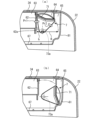
- (a) is a cross-sectional view showing the dehumidifier according to Embodiment 2 with the shutter closing the second air passage
- (b) is a cross-sectional view showing the shutter opening the second air passage. It is a cross-sectional view shown in a state.
- FIG. 7 is a longitudinal cross-sectional view showing a shutter mounting structure in a dehumidifier according to Embodiment 3
- FIG. 2 is a vertical cross-sectional view of a conventional dehumidifier. It is a structural diagram which operates the shutter of a dehumidifier with a stepping motor.
- FIG. 1 is a perspective view of a dehumidifier 1 according to the first embodiment, viewed from the front side.
- FIG. 2 is a perspective view of the dehumidifier 1 seen from the rear side.
- FIG. 3 is an exploded perspective view of the dehumidifier 1.
- FIG. 4 is an exploded perspective view of the vicinity of the intake port of the dehumidifier 1.
- 5 is a longitudinal cross-sectional view of the dehumidifier 1 taken along the line AA in FIG. 1
- FIG. 6 is a cross-sectional view of the dehumidifier 1 taken along the line BB in FIG.
- the AA line and the BB line pass through the rotation center of a sirocco fan 42, which will be described later.
- FIG. 1 is a perspective view of a dehumidifier 1 according to the first embodiment, viewed from the front side.
- FIG. 2 is a perspective view of the dehumidifier 1 seen from the rear side.
- FIG. 3 is an
- FIG. 7 is a perspective view showing the dehumidifier 1 with the case removed.
- FIG. 8 is a detailed view showing a portion Q surrounded by a broken line in FIG. 5, and
- FIG. 9 is an exploded perspective view of the heat exchanger 38 and heat exchanger retainer 26 shown in FIG.
- the front-rear direction of the dehumidifier 1 is the X-axis direction
- the width direction is the Y-axis direction
- the up-down direction perpendicular to the X-axis direction and the Y-axis direction is the Z-axis direction.
- the left side in FIG. 5 is the front side
- the right side is the rear side and the rear side
- the front side perpendicular to the page is the left side
- the back side is the right side.
- the dehumidifier 1 includes a case 2 as a housing.
- the case 2 has a front case 21 forming a front part and a rear case 22 forming a back part.
- a box-shaped case 2 that can stand on its own is formed by fixing the front case 21 and the rear case 22 with, for example, screws in a state where they are aligned front and back.
- the operation display section 23 includes a switch for the user to operate the dehumidifier 1, a display section that displays the operating state and mode of the dehumidifier 1, an audio notification section, and the like.
- the switches include, for example, an operation switch that starts/stops the operation of the dehumidifier 1, an operation mode changeover switch that changes the operation mode, and the like.
- the operation mode changeover switch allows switching between a dehumidification-oriented operation mode that emphasizes dehumidification and an air-cleaning-oriented operation mode that emphasizes air purification.
- a base 24 is provided at the bottom of the case 2, and swivel casters 24a for moving the dehumidifier 1 are provided at the four corners of the base 24.
- a rib 24b for positioning the water storage tank 26 is formed on the upper surface of the base 24.
- a front panel 25, which constitutes a part of the front case 21, is fixed to the front surface of the water storage tank 26.
- a window 25a is provided on the front panel 25, and the amount of drain water in the water storage tank 26 can be confirmed through the window 25a.
- the case 2 has an intake port 31 and an outlet 32 formed therein.
- the intake port 31 is an opening for taking in air from the outside of the case 2 to the inside.
- the air outlet 32 is an opening for sending air from the inside of the case 2 to the outside.
- the air intake port 31 is formed in the rear case 22, and the air outlet 32 is formed in the front case 21.
- a louver 33 is provided near the air outlet 32 for adjusting the direction in which air is sent out from the air outlet 32.
- As the louver 33 a known one having a plate-like member that is movable in the vertical direction can be used.
- a stepping motor (not shown) for driving the louver 33 is attached to a side surface of the louver 33.
- a pre-filter 34 is provided as an intake port cover that covers the entire intake port 31.
- the pre-filter 34 is detachably attached to the rear case 22 by a plurality of claws 34a provided on its outer periphery.
- a mesh net 34b is welded and fixed to the pre-filter 34 to prevent foreign matter such as dust from being sucked in through the intake port 31.
- the pre-filter 34 also has intake ports 34c and 34d for an odor sensor and a dust sensor. Thereby, when removing the pre-filter 34 from the rear case 22 and cleaning various filters 65 and 66, which will be described later, these intake ports 34c and 34d can also be cleaned.
- a hose connection hole 34e is provided at the lower part of the pre-filter 34 through which a drain hose (not shown) for discharging drain water to the outside of the dehumidifier 1 is passed.
- the hose connection hole 34e communicates with a power cord storage section 36 inside the case 2, and when storing the dehumidifier 1, the power cord 35 can be passed through the hose connection hole 34e and stored in the power cord storage section 36. can. Thereby, there is no need to provide a dedicated through hole for the power cord on the back of the rear case 22, the appearance is neat, and the external design of the dehumidifier 1 is not impaired.
- a drain water receiver 37 is fitted into the upper part of the rib 24b of the base 24.
- a drain water stopper 37a is rotatably attached to the drain water receiver 37 to temporarily stop the drainage of drain water to the water storage tank 26, and is normally biased by a spring in the direction of stopping the drain water. Then, with the water storage tank 26 housed in the storage position, the drain water can be drained into the water storage tank 26 by pushing the drain stop 37a in the opposite direction to the negative direction of the spring.
- a heat exchanger 38 which is a dehumidifying means, is arranged above the drain water receiver 37.
- the heat exchanger 38 includes an evaporator 38a, a main condenser 38b, a sub-condenser 38c, and a heat exchanger tube 38d.
- the evaporator 38a is cooled by a refrigerant circulating from a compressor 54, which will be described later, and can dehumidify humid air by condensing it.
- the water droplets condensed on the evaporator 38a drip into the drain water receiver 37, and are drained into the water storage tank 26 through the drain pipe 37b of the drain water receiver 37.
- the dehumidified air is returned to room temperature in the main condenser 38b and the sub-condenser 38c, and then is discharged from the air outlet 32 via a scroll space 45, which will be described later.
- a drainage hose (not shown) can be directly connected to the drainage pipe 37b. In this case, continuous drainage is possible by inserting the drainage hose into the hose connection hole 34e and pulling it out of the case 2.
- a blowing means 4 is arranged in front of the heat exchanger 38.
- the blowing means 4 includes a fan motor 41 and a sirocco fan 42.
- the sirocco fan 42 is arranged in a scroll space 45 defined by a casing 43 and a partition plate 44. Air sucked in through the bellmouth-shaped hole 44a of the partition plate 44 by the rotation of the sirocco fan 42 is discharged from the air outlet 32 located above the casing 43, and the direction of the air is changed by the louver 33.
- a heat exchanger holder 51 that holds the heat exchanger 38 is arranged above the heat exchanger 38.
- the heat exchanger holder 51 includes an air path guide plate 51a and a power supply board case 51b.
- the air path guide plate 51a is arranged to cover the upper surfaces of the evaporator 38a and the main condenser 38b. Thereby, an upper air passage 51c of the heat exchanger 38 is formed between the air passage guide plate 51a and the power supply board case 51b.
- the air path of the heat exchanger 38 includes a first path through which the airflow taken in from the intake port 31 passes through the evaporator 38a, the main condenser 38b, and the sub-condenser 38c, and a first path through which the airflow passes through the evaporator 38a and the main condenser 38b. and a second path leading to the sub-condenser 38c.
- a power supply board unit 52 is provided on the power supply board case 51b.
- the power supply board unit 52 operates in conjunction with an operation board 53 attached to the operation display section 23 to operate a motor for the louver 33, a compressor 54 installed on the base 24, a fan motor 41, and a motor for the shutter 7, which will be described later. Drive control of the motor 8, etc.
- Wiring from the compressor 54 and fan motor 41 passes through the side surface of the partition plate 44 and a wiring guide 55, and is connected to the power supply board unit 52.
- a power wiring guide plate 56 is attached to the rear of the drain water receiver 37 and the heat exchanger holder 51 so as to vertically straddle the drain water receiver 37 and the heat exchanger holder 51.
- the power supply wiring guide plate 56 functions as a holding member for routing wiring such as a power supply line and a ground line.
- the power supply wiring guide plate 56 By providing the power supply wiring guide plate 56, it becomes possible to route the wiring to the power supply board unit 52 independently from the wiring guide 55 through which the wiring from the compressor 54 and fan motor 41 passes, and over the shortest distance. Therefore, the influence of power supply noise etc. can be reduced.
- the power supply wiring guide plate 56 becomes a rigid body that connects the drain water receiver 37 and the heat exchanger holder 51, it is possible to prevent the heat exchanger 38 from falling off.
- An air passage forming frame 61 is attached to the rear case 22 so as to face the air intake port 31 .
- two air passage partition plates 62 that are longitudinal in the vertical direction are arranged with an interval in the left and right directions. These two air passage partition plates 62 partition the inside of the air passage forming frame 61 into a first air passage 63 and a second air passage 64, which will be described later. That is, the first air passage 63 is defined at the center of the air passage forming frame 61 in the left-right direction by the two air passage partition plates 62 and the upper and lower walls of the air passage forming frame 61.
- Two second air passages 64 are defined on both sides of the first air passage 63 in the left and right direction by each air passage partition plate 62 and the upper wall, lower wall, and side wall of the air passage forming frame 61. be done. In this way, the left and right spaces of the first air passage 63 partitioned by the air passage partition plate 62 become second air passages 64, respectively.
- air purifying filters such as a HEPA filter 65 and a deodorizing filter 66 are arranged as air purifying means. Since the HEPA filter 65 is disposed at the entrance of the first air passage 63, the entrance 64a of the second air passage 64 is located outside in the left-right direction of the HEPA filter 65, which is an air purifying means.
- An air intake grid 67 is disposed between the deodorizing filter 66 and the heat exchanger 38, so that airflow is uniformly sent to the heat exchanger 38.
- the first air passage 63 and the second air passage 64 are configured to join before the heat exchanger 38, specifically, on the upstream side of the intake grid 67.
- FIG. 10 is an exploded perspective view of the shutter 7 of the dehumidifier 1 according to the first embodiment.
- FIG. 11(a) is a cross-sectional view showing the dehumidifier 1 according to the first embodiment in a state where the shutter 7 closes the second air passage 64, and
- FIG. 11(b) shows the dehumidifier 1 according to the first embodiment.
- FIG. 4 is a cross-sectional view showing a state in which the air passage 64 of FIG.
- the shutter 7 includes a plate-shaped shielding wall 71 that is elongated in the vertical direction, an upper plate 72 and a lower plate 73 that are fan-shaped in plan view provided at the upper and lower ends of the shielding wall 71, respectively, and an upper plate provided on the upper surface of the upper plate 72. It has a rotation shaft 72a and a lower rotation shaft 73a provided on the lower surface of the lower plate 73.
- the upper plate 72 and the lower plate 73 function as holding plates that hold the shielding wall 71.
- the upper rotation shaft 72a and the lower rotation shaft 73a are inserted and fitted into an upper bearing 61a and a lower bearing 61b, respectively, which are provided on the upper wall and the lower wall of the air passage forming frame 61, respectively.
- a shutter 7 is rotatably supported.
- a motor 8 as a driving means is directly attached to the upper rotation shaft 72a.
- a stepping motor can be used.
- the rotational position of the shutter 7 is controlled by driving and controlling the motor 8 by a control section, which will be described later. Specifically, there is a closed position where the shielding wall 71 shields the second air passage 64 and blocks the airflow in the second air passage 64, and a closed position where the shield wall 71 opens the second air passage 64 and the second air passage 64 is closed.
- the shutter 7 is rotated around the rotation axes 72a and 73a between the open position and the open position that allows airflow in the second air passage 64.
- the stepping motor 8 has a constant holding torque in a state where no current is flowing. Therefore, once the shutter 7 is rotated to the closed position or the open position by the stepping motor 8, the shutter 7 will not rotate unless a rotational force exceeding the holding torque is applied.
- the shutter 7 is arranged in such a posture that the shielding wall 71 is parallel to the HEPA filter 65 in the closed position.
- the rotation shafts 72a and 73a which serve as rotation fulcrums, are arranged within the second air passage 64, and these rotation shafts 72a and 73a are positioned closer to the ends of the shielding wall 71 than at the left and right ends. It is arranged inside, specifically, on the perpendicular bisector Lv of the shielding wall 71.
- the rotational forces Pr1 and Pr2 that act on the shutter 7 due to the differential pressure applied to the shielding wall 71 are dispersed in two directions to the left and right of the rotation shafts 72a and 73a.
- the differential pressure applied to the left-right inner portion of the shielding wall 71 becomes a turning force Pr1
- the differential pressure applied to the left-right outer portion of the shielding wall 71 becomes a turning force Pr2.
- the rotational forces Pr1 and Pr2 in two different directions acting around the rotational shafts 72a and 73a cancel each other out in the left and right directions, so that the holding torque of the motor 8 is suppressed to be smaller than the holding torque of the motor 8, thereby causing the shutter 7 to move in the opening direction. movement is prevented. Therefore, it is possible to prevent deterioration in air cleaning performance and generation of crevice noise.
- Seal portions 71a and 71b that function as seal surfaces when the shutter 7 is in the closed position are provided at both left and right ends of the shielding wall 71.
- One seal part 71a abuts against the outer wall surface 62a on the left and right outer side of the air passage partition plate 62
- the other seal part 71b is a part of the air passage forming frame 61 located at the inner end of the rear case 22. It is configured to abut against a front surface 61c of a protruding portion that protrudes forward from.
- a clearance is required between the seal portions 71a, 71b and the wall surfaces 62a, 61c defining the second air passage 64.
- the second air passage 64 When the shutters 7 are respectively rotated outward from the closed position to the open position, that is, when the seal portions 71a and 71b of the shielding wall 71 are separated from the wall surfaces 62a and 61c, the second air passage 64 is opened and the second air passage 64 is opened. Air current can flow through the second air passage 64.
- the second air passage 64 has a storage space 68 that bulges outward in the left-right direction, and the shielding wall 71 in the open position is stored in this storage space 68. This is advantageous in that the pressure loss in the second air passage 64 can be reduced when the shutter 7 is in the open position.
- the dehumidifier 1 can be made more compact than in the case where a storage space is provided inside the second air passage 64 in the left-right direction, and the external design of the dehumidifier 1 is not impaired.
- FIG. 12 is a control block diagram of the dehumidifier 1 according to the first embodiment.
- the power supply board unit 52 and the operation board 53 constitute a control section.
- the power supply board unit 52 has a function as a main control section.
- the power supply board unit 52 includes a power supply section to which the power cord 35 is connected, a CPU, a drive circuit, and a storage section.
- the CPU has an internal timer as a timer.
- a plurality of drive circuits are provided corresponding to the compressor 54, the motor for the louver 33, the fan motor 41, and the motor 8 for the shutter 7, but one drive circuit is provided to unify the motor. It may also be configured to be driven.
- FIG. 13 is a flowchart showing an example of the operation of the dehumidifier 1 according to the first embodiment.
- step S12 the second air passage 64 is opened by driving the motor 8 and rotating the shutter 7 to the open position.
- the fan motor 41 is driven to rotate the sirocco fan 42 (step S13).
- the compressor 54 is driven (step S14).
- the sirocco fan 42 sucks air containing moisture from the intake port 31. Air sucked in from the intake port 31 passes through a HEPA filter 65 and a deodorizing filter 66 arranged in the first air path 63, and flows to the heat exchanger 38. At the same time, some air passes through the open second air passage 64 and flows directly to the heat exchanger 38 . Since the air passing through the second air passage 64 does not pass through the filters 65 and 66, the pressure loss is smaller than that through the first air passage 63, and more air can be sent to the heat exchanger 38.
- the humid air is dehumidified by condensation in the evaporator 38a.
- the dehumidified air is returned to room temperature in the main condenser 38b and the sub-condenser 38c, and then is discharged from the blow-off port 32 through the scroll space 45.
- the step motor for the louver 33 it is possible to change the angle of the louver 33 in the vertical direction. As a result, air can be blown upward to generate circulating airflow within a room to dehumidify the room, or laundry can be blown with air to dry it.
- the drain water stopper 37a closes the drain port of the drain pipe 37b and prevents drain water from being drained. Further, when a drain hose is attached to the drain pipe 37b, drain water passes through the drain hose and is drained out of the case 2.
- step S15 the second air passage 64 is closed by driving the motor 8 and rotating the shutter 7 to the closed position.
- the fan motor 41 is driven to rotate the sirocco fan 42 (step S16).
- the shielding wall 71 blocks the air flow in the second air passage 64, almost all of the air sucked in from the intake port 31 passes through the first air passage 63, and the HEPA It is cleaned by a filter 65 and a deodorizing filter 66. Therefore, the air blown from the outlet 32 becomes clean air and exhibits an excellent air purifying function.
- the shutter 7 since the second air passage 64 on the downstream side of the shielding wall 71 has a negative pressure with respect to the external pressure on the upstream side of the shielding wall 71, the shutter 7 has a differential pressure between the external pressure and the negative pressure. Accordingly, a rotational force acts to rotate the shutter 7.
- the rotation shafts 72a, 73a of the shutter 7 are arranged in the second air passage 64, and these rotation shafts 72a, 73a are arranged not at the left and right ends of the shielding wall 71. It was arranged inside the end, specifically, on the perpendicular bisector Lv of the shielding wall 71.
- the rotational forces Pr1 and Pr2 that act on the shutter 7 due to the differential pressure applied to the shielding wall 71 are dispersed in two directions to the left and right of the rotation shafts 72a and 73a.
- the differential pressure applied to the left-right inner portion of the shielding wall 71 becomes a turning force Pr1
- the differential pressure applied to the left-right outer portion of the shielding wall 71 becomes a turning force Pr2.
- the rotational forces Pr1 and Pr2 in two different directions acting around the rotational shafts 72a and 73a cancel each other out in the left and right directions, so that the holding torque of the motor 8 is suppressed to be smaller than the holding torque.
- the stepping motor 8 that drives the shutter 7 is connected to the upper rotation shaft 72a of the shutter 7, water droplets may fall onto the stepping motor 8 when, for example, the second air passage 64 is wiped with water during maintenance. This prevents failure of the stepping motor 8 due to water wetting.
- FIG. 14(a) is a cross-sectional view showing the dehumidifier 1 according to the second embodiment with the shutter closed
- FIG. 14(b) is a cross-sectional view showing the dehumidifier 1 with the shutter open. It is.
- illustration of the HEPA filter 65 and the deodorizing filter 66 is omitted.
- the rotation shafts 72a and 73a which serve as rotation fulcrums, are located inside the middle of the second air passage 64 in the left-right direction.
- the space for rotating the shutter 7 is determined by the distance h in the left-right direction from the wall surface 62a of the air passage partition plate 62, which is the inner wall of the second air passage 64, to the rotation shafts 72a and 73a, and the rotation radius R of the shutter 7.
- the rotation shafts 72a and 73a further inward in the left-right direction than in the first embodiment, the space in which the shutter 7 is rotated can be made smaller.
- the shutter 7 is arranged in such a manner that the shielding wall 71 in the closed position is inclined with respect to the HEPA filter 65, and there is a possibility that the left and right balance of the rotational force acting on the shutter 7 may be lost.
- the shielding wall 71 in order to equalize the rotational force acting on the shutter 7 in the left-right direction, is formed into a bent or curved shape in the cross section of the shutter 7.
- the shielding wall 71 is bent into a substantially dogleg shape so that the rotational forces Pr1 and Pr2 applied to the shielding wall 71 are equalized in the left-right direction. is being adjusted. Further, by bending or curving the shielding wall 71, the strength against bending of the shielding wall 71 in the longitudinal direction can be improved. Furthermore, when the shutter 7 is open as shown in FIG. can be further reduced.
- FIG. 15 is a longitudinal sectional view showing the mounting structure of the shutter 7 in the dehumidifier according to the third embodiment.
- FIG. 15 shows the positional relationship between the rotation shaft 72a of the shutter 7 and the rotation shaft 81a of the stepping motor 8.
- the rotating shaft 81a of the stepping motor 8, which is arranged above the shutter 7, is shifted from the rotating shaft 72a of the shutter 7 in the left-right direction.
- a gear 72b is fitted onto the upper end of the rotation shaft 72a of the shutter 7.
- a gear 81b that meshes with the gear 72b is fitted onto the lower end of the rotating shaft 81a of the stepping motor 8.
Landscapes
- Engineering & Computer Science (AREA)
- Chemical & Material Sciences (AREA)
- Combustion & Propulsion (AREA)
- Mechanical Engineering (AREA)
- General Engineering & Computer Science (AREA)
- Drying Of Gases (AREA)
Abstract
空気清浄に重点をおいた運転を行う場合に閉じられるシャッターに差圧が作用したとしても、空気清浄性能の低下及び隙間音の発生を防止することができる除湿機を提供する。 除湿機は、吸気口および吹出口を有する筐体と、筐体の内部に配置され、吸気口から吹出口へ至る気流を発生させる送風手段と、筐体の内部に配置される空気清浄化手段と、筐体の内部に配置され、気流の中の水分を除去する除湿手段と、気流が空気清浄化手段を通過して除湿手段に至る第一の風路と、気流が空気清浄化手段を通過せずに除湿手段に至る第二の風路と、第二の風路を開閉する開閉手段と、を備える。開閉手段は、第二の風路の内部に配置されて上下方向にのびる回動軸を中心に、第二の風路を遮蔽する閉位置と第二の風路を開放する開位置との間を回動可能なシャッターを有し、閉位置でのシャッターの左右方向端部よりも内側に回動軸を配置した。
Description
本開示は、除湿機に関する。
図16は、特許文献1に開示された従来の除湿機100Aを示す縦断面図である。除湿機100Aは、吸気口101と、除湿手段としての熱交換器102とを備える。吸気口101から熱交換器102につながる風路103には、空気清浄化手段としてのフィルター104と、フィルター104の下流側の風路103と熱交換器102とを仕切る吸気格子105と、が配置されている。吸気口101から熱交換器102を透過して見ると、熱交換器102の一部分を覆わないようにフィルター104が配置されている。このため、送風手段106によって発生させた気流の一部は、フィルター104を通過せずに熱交換器102に到達する。
フィルター104が配置されていない風路103aには、上下方向にスライドすることで風路103aを開閉可能なシャッター107が設けられている。シャッター107には把手108が設けられ、ユーザーがシャッター107を手動でスライドさせることができ。シャッター107を下方にスライドさせて風路103aを開くと、多くの気流が熱交換器102に取り込まれるため、除湿に重点をおいた運転となる。一方、シャッター107を上方にスライドさせて風路103aを閉じると、ほとんどの気流がフィルタ104を通過して清浄化され、清浄化された気流が熱交換器102に取り込まれるため、空気清浄に重点をおいた運転となる。
このように、除湿機100Aは、ユーザーによるシャッター107の操作によって、除湿に重点をおいた運転と空気清浄に重点をおいた運転との間で切替可能に構成されている。なお、特許文献1には、シャッターとして回転運動により開閉可能なブラインドタイプのシャッターを用いることが記載されている。
特許文献1にはブラインドタイプのシャッターの具体的な構造は記載されていないが、図17に示すように除湿機100Bを構成することが考えられる。除湿機100Bは、フィルター104が配置されていない風路103aを開閉可能なブラインドタイプのシャッター109を備える。このシャッター109は、上下方向に長手の板状に形成し得る。シャッター109の幅方向の端部には、シャッター109の回動軌跡と干渉しない位置に配置されるモータ110の回転軸110aが連結されている。モータ110を駆動することにより、仮想線で示す閉位置と、風路103aを開放する開位置との間で、回転軸110aを中心にシャッター109を回動させることができる。
除湿機100Bが空気清浄に重点をおいた運転を行う場合、モータ110を駆動してシャッター109を閉位置に回動させる。この閉位置に回動させた状態で送風手段106により気流を発生させると、シャッター109の下流側の風路103aは、シャッター109の上流側の気流の圧力(以下「外気圧」という)に対して負圧となる。このため、シャッター109には、外気圧と負圧との差圧に応じて、シャッター109を閉位置から開位置に回転させようとする一方向の回動力Prが作用する。シャッター109に作用する回動力Prは、差圧に比例して大きくなり、特に、送風量が大きい場合には顕著になる。そして、シャッター109に作用する回動力Prがモータ110の保持トルクよりも大きくなると、シャッター109が開方向に動いてフィルタ104との間に隙間Gpが発生する。隙間Gpを介した風漏れにより、空気清浄性能が低下すると共に隙間音が発生するという問題がある。
本発明は、上記のような課題を解決するためになされたものである。本発明の目的は、空気清浄に重点をおいた運転を行う場合に閉じられるシャッターに差圧が作用したとしても、空気清浄性能の低下及び隙間音の発生を防止することができる除湿機を提供することである。
本開示に係る除湿機は、吸気口および吹出口を有する筐体と、前記筐体の内部に配置され、前記吸気口から前記吹出口へ至る気流を発生させる送風手段と、前記筐体の内部に配置される空気清浄化手段と、前記筐体の内部に配置され、前記気流の中の水分を除去する除湿手段と、前記気流が前記空気清浄化手段を通過して前記除湿手段に至る第一の風路と、前記気流が前記空気清浄化手段を通過せずに前記除湿手段に至る第二の風路と、前記第二の風路を開閉する開閉手段と、を備える。前記開閉手段は、前記第二の風路の内部に配置されて上下方向にのびる回動軸を中心に、前記第二の風路を遮蔽する閉位置と前記第二の風路を開放する開位置との間を回動可能なシャッターを有し、前記閉位置での前記シャッターの上下方向に直交する左右方向端部よりも内側に前記回動軸を配置した。
本開示によれば、第二の風路を閉じる閉位置でのシャッターの左右方向端部よりも内側に回動軸を配置したため、閉位置でのシャッターの上流側と下流側との間に差圧が生じたとしても、異なる二方向の回動力が回動軸まわりに作用する。これら二方向の回動力が互いに打ち消し合い、打ち消し合った後の回動力がシャッターを回動させるモータの保持トルクよりも小さく抑えられるため、シャッターが開方向に動くことが防止される。従って、空気清浄性能の低下及び隙間音の発生を防止することができる。
以下、図面を参照して、実施の形態について説明する。各図における同一の符号は、同一の部分または相当する部分を示す。また、本開示では、重複する説明については適宜に簡略化または省略する。なお、本開示は、以下の実施の形態で説明する構成のうち、組み合わせ可能な構成のあらゆる組み合わせを含み得るものである。
実施の形態1.
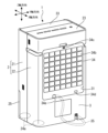
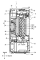
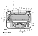
図1は、実施の形態1による除湿機1を前側から見た斜視図である。図2は、除湿機1を後側から見た斜視図である。図3は、除湿機1の分解斜視図である。図4は、除湿機1の吸気口近傍の分解斜視図である。図5は、除湿機1を図1中のA-A線で切断した縦断面図であり、図6は、除湿機1を図1中のB-B線で切断した横断面図である。A-A線及びB-B線は、後述するシロッコファン42の回転中心を通る。また、図7は、除湿機1をケースが外された状態で示す斜視図である。図8は、図5中に破線で囲んだ部分Qを示す詳細図であり、図9は、図5に示す熱交換器38及び熱交換器押さえ26の分解斜視図である。
図1は、実施の形態1による除湿機1を前側から見た斜視図である。図2は、除湿機1を後側から見た斜視図である。図3は、除湿機1の分解斜視図である。図4は、除湿機1の吸気口近傍の分解斜視図である。図5は、除湿機1を図1中のA-A線で切断した縦断面図であり、図6は、除湿機1を図1中のB-B線で切断した横断面図である。A-A線及びB-B線は、後述するシロッコファン42の回転中心を通る。また、図7は、除湿機1をケースが外された状態で示す斜視図である。図8は、図5中に破線で囲んだ部分Qを示す詳細図であり、図9は、図5に示す熱交換器38及び熱交換器押さえ26の分解斜視図である。
本実施の形態1では、除湿機1の前後方向をX軸方向、幅方向をY軸方向、X軸方向及びY軸方向に直交する上下方向をZ軸方向とする。また、図5における左側を前側及び正面側、右側を後側及び背面側、紙面に垂直な手前側を左側、奥側を右側とする。
除湿機1は、筐体としてのケース2を備える。ケース2は、正面部分を形成する前ケース21と、背面部分を形成する後ケース22とを有する。前ケース21と後ケース22とを前後で位置合わせした状態で例えばネジなどにより固定することで、自立可能な箱状のケース2が形成される。
ケース2の上部には、操作表示部23が設けられている。操作表示部23は、使用者が除湿機1の運転を操作するスイッチ、除湿機1の運転状態及び運転モードを表示する表示部、並びに、音声報知部などを有する。スイッチには、例えば、除湿機1の運転を開始/停止する運転スイッチや、運転モードを切り替える運転モード切替スイッチなどが含まれる。詳細は後述するが、運転モード切替スイッチにより、除湿に重点をおいた除湿重視運転モードと、空気清浄に重点をおいた空気清浄重視運転モードとの間で切り替えることができる。ケース2の底部にはベース24が設けられ、ベース24の4隅には、除湿機1を移動させるための自在キャスター24aが設けられている。ベース24の上面には、貯水タンク26を位置決めするリブ24bが形成されている。貯水タンク26の前面には、前ケース21の一部を構成する前面パネル25が固定されている。前面パネル25には窓25aが設けられ、窓25a越しに貯水タンク26内のドレン水の量を確認できる。そして、貯水タンク26が満水になると、前面パネル25と共に貯水タンク26を除湿機1の前方に引き出し、貯水タンク26内のドレン水を捨てることができる。
ケース2には吸気口31と吹出口32とが形成されている。吸気口31は、ケース2の外部から内部へ空気を取り込むための開口である。吹出口32は、ケース2の内部から外部へ空気を送り出すための開口である。吸気口31は後ケース22に形成され、吹出口32は前ケース21に形成されている。吹出口32の近くには、吹出口32から空気が送り出される方向を調整するためのルーバー33が設けられている。ルーバー33としては、上下方向に可動する板状部材を有する公知のものを用いることができる。ルーバー33の側面には、ルーバー33を駆動するための図示省略のステッピングモータが付設されている。
図2及び図4も参照して、除湿機1を後方から見ると、吸気口31の全体を覆う吸気口カバーとしてのプレフィルター34が設けられている。プレフィルター34は、その外周部に設けられた複数のツメ34aによって、後ケース22に対して着脱自在に取り付けられている。プレフィルター34には、埃などの異物が吸気口31から吸い込まれることを防止するためのメッシュネット34bが溶着固定されている。プレフィルター34にはまた、臭いセンサ用及び埃センサ用の吸気口34c,34dが開設されている。これにより、後ケース22からプレフィルター34を取り外して後述する各種フィルタ65,66を洗浄する際に、これらの吸気口34c,34dの洗浄も併せて行うことができる。プレフィルター34の下部には、除湿機1の外部にドレン水を排水するための排水ホース(図示せず)を通すためのホース接続穴34eが開設されている。ホース接続穴34eはケース2内部の電源コード収納部36に連通しており、除湿機1を収納する際に、電源コード35をホース接続穴34eに通して電源コード収納部36に収容することができる。これにより、後ケース22の背面に電源コード専用の通し穴を開設する必要がなく、見た目がすっきりして、除湿機1の外観意匠が損なわれることがない。
次に、図3~図9も参照して、除湿機1の内部構造について説明する。ベース24のリブ24bの上部には、ドレン水受け37が嵌合されている。ドレン水受け37には貯水タンク26へのドレン水の排水を一時的に止めるドレン水止め37aが回転自在に取り付けてあり、通常はバネによってドレン水を止める方向に負勢されている。そして、貯水タンク26が収納位置に収納された状態で、ドレン水止め37aをバネの負勢方向と逆に押すことで、ドレン水を貯水タンク26に排水することができる。
ドレン水受け37の上には除湿手段である熱交換器38が配置されている。熱交換器38は蒸発器38aと、メイン凝縮器38bと、サブ凝縮器38cと、熱交配管38dと、を有する。蒸発器38aは、後述する圧縮機54から循環する冷媒によって冷却されることで、湿気を含んだ空気を結露させて除湿することができる。蒸発器38aに結露した水滴はドレン水受け37に滴下し、ドレン水受け37の排水パイプ37bを通って貯水タンク26に排水される。除湿された空気は、メイン凝縮器38b及びサブ凝縮器38cにて常温に戻された後、後述するスクロール空間45を介して吹出口32から排出される。なお、排水パイプ37bに直接、排水ホース(図示せず)を接続し得る。この場合、排水ホースをホース接続穴34eに挿通してケース2の外へ引き出しておくことで、連続排水が可能である。
熱交換器38の前方には、送風手段4が配置されている。送風手段4は、ファンモータ41と、シロッコファン42と、を有する。シロッコファン42は、ケーシング43と仕切り板44とで画成されるスクロール空間45に配置されている。シロッコファン42の回転によって仕切り板44のベルマウス形状穴44aから吸い込まれた空気は、ケーシング43上方に位置する吹出口32から排出され、ルーバー33によって送風方向が変えられるようになっている。
熱交換器38の上方には熱交換器38を保持する熱交換器押さえ51が配置されている。熱交換器押さえ51は、風路ガイド板51aと、電源基板ケース51bと、を有する。風路ガイド板51aは、蒸発器38a及びメイン凝縮器38bの各上面を覆うように配置されている。これにより、風路ガイド板51aと電源基板ケース51bとの間に熱交換器38の上部風路51cが形成される。熱交換器38の風路は、吸気口31から取り込まれた気流が蒸発器38a、メイン凝縮器38b及びサブ凝縮器38cを通る第1の経路と、蒸発器38a及びメイン凝縮器38bを迂回してサブ凝縮器38cへとつながる第2の経路との二つの経路で構成されている。
また、電源基板ケース51b上には電源基板ユニット52が設けられる。電源基板ユニット52は、操作表示部23に取り付けられた操作基板53と連動して、ルーバー33用のモータ、ベース24上に設置される圧縮機54、ファンモータ41や、後述するシャッター7用のモータ8などを駆動制御する。圧縮機54及びファンモータ41からの配線は、仕切り板44の側面と、配線ガイド55とを通って、電源基板ユニット52に接続される。ドレン水受け37及び熱交換器押さえ51の後方には、これらドレン水受け37及び熱交換器押さえ51を上下方向に跨るように電源配線ガイド板56が取り付けられている。電源配線ガイド板56は、電源線やアース線などの配線を引き回すための保持部材として機能する。電源配線ガイド板56を設けることで、電源基板ユニット52への配線を、圧縮機54やファンモータ41からの配線が通る配線ガイド55から独立して、かつ、最短距離で引き回すことが可能となるので、電源ノイズなどの影響を小さくすることができる。また、電源配線ガイド板56は、ドレン水受け37と熱交換器押さえ51を接続する剛性体となるため、熱交換器38の脱落を防止することができる。
次に、吸気口31近傍の内部構造について説明する。後ケース22には、吸気口31に対向させて風路形成枠61が取り付けられている。風路形成枠61の内部には、上下方向に長手の二つの風路仕切り板62が左右方向に間隔を存して配置されている。これら二つの風路仕切り板62により、風路形成枠61の内部が後述する第一の風路63と第二の風路64とに仕切られる。即ち、二つの風路仕切り板62と、風路形成枠61の上壁及び下壁とによって、風路形成枠61の左右方向中央に第一の風路63が画成される。第一の風路63の左右方向の両外側に、各風路仕切り板62と、風路形成枠61の上壁、下壁及び側壁とによって、二つの第二の風路64が夫々画成される。このように、風路仕切り板62によって仕切られた第一の風路63の左右の空間が、夫々第二の風路64となる。第一の風路63には、空気清浄化手段として、HEPAフィルタ65及び脱臭フィルタ66などの空気清浄化フィルタが配置される。第一の風路63の入口にはHEPAフィルタ65が配置されているため、第二の風路64の入口64aは、空気清浄化手段たるHEPAフィルタ65の左右方向外側に位置する。脱臭フィルタ66と熱交換器38との間には吸気格子67が配置され、熱交換器38に対して均等に気流が送り込まれるようにしている。そして、第一の風路63と第二の風路64とは、熱交換器38の手前、具体的には、吸気格子67の上流側で合流するように構成されている。
図10及び図11も参照して、第二の風路64には、開閉手段としてのシャッター7が設けられている。図10は、実施の形態1による除湿機1のシャッター7の分解斜視図である。図11(a)は、実施の形態1による除湿機1をシャッター7が第二の風路64を閉じている状態を示す横断面図であり、図11(b)は、シャッター7が第二の風路64を開放している状態を示す横断面図である。
シャッター7は、上下方向に長手の板状の遮蔽壁71と、遮蔽壁71の上端及び下端に夫々設けられる平面視扇形の上板72及び下板73と、上板72の上面に設けられる上側回動軸72aと、下板73の下面に設けられる下側回動軸73aと、を有する。上板72及び下板73は、遮蔽壁71を保持する保持板として機能する。上側回動軸72a及び下側回動軸73aは、風路形成枠61の上壁及び下壁に夫々設けられた上側軸受け61a及び下側軸受け61bに夫々挿入嵌合されており、これにより、シャッター7が回動自在に支承されている。上側回動軸72aには駆動手段としてのモータ8が直接取り付けられている。モータ8としては、ステッピングモータを利用することができる。後述する制御部によりモータ8を駆動制御することで、シャッター7の回動位置を制御する。具体的には、遮蔽壁71が第二の風路64を遮蔽して第二の風路64の気流の流れを遮る閉位置と、遮蔽壁71が第二の風路64を開放して第二の風路64の気流を許可する開位置との間で、シャッター7を回動軸72a,73aまわりに回動させる。また、ステッピングモータ8は、電流が流れていない状態で一定の保持トルクを有する。このため、ステッピングモータ8によりシャッター7を閉位置または開位置に一旦回動させた後は、保持トルクを超える回動力が付与されない限り、シャッター7は回動しない。
シャッター7を閉位置に回動させた状態で、送風手段4により気流を発生させると、遮蔽壁71の下流側の第二の風路64は、遮蔽壁71の上流側の外気圧に対して負圧となる。このため、シャッター7には、外気圧と負圧との差圧に応じて、シャッター7を回動させようとする回動力Pr1,Pr2が作用する。
ここで、本実施の形態では、閉位置での遮蔽壁71がHEPAフィルタ65と平行となる姿勢でシャッター7を配置している。そして、回動支点となる回動軸72a,73aを第二の風路64内に配置すると共に、これらの回動軸72a,73aを遮蔽壁71の左右方向の端部ではなく端部よりも内側、具体的には、遮蔽壁71の垂直二等分線Lv上に配置している。これにより、遮蔽壁71に加わる差圧に起因してシャッター7に作用する回動力Pr1,Pr2が、回動軸72a,73aの左右二方向に分散される。詳細には、遮蔽壁71の左右方向内側部分に加わる差圧は回動力Pr1となり、遮蔽壁71の左右方向外側部分に加わる差圧は回動力Pr2となる。これら回動軸72a,73aまわりに作用する異なる二方向の回動力Pr1,Pr2が左右方向で互いに打ち消し合うことで、モータ8の保持トルクよりも小さく抑えられ、これにより、シャッター7が開方向に動くことが防止される。従って、空気清浄性能の低下及び隙間音の発生を防止することができる。
遮蔽壁71の左右両端には、シャッター7の閉位置で、シール面として機能するシール部71a,71bが設けられている。一方のシール部71aは、風路仕切り板62の左右方向外側の外壁面62aに対して突き当てられ、他方のシール部71bは、後ケース22の内側端に位置する風路形成枠61の部分から前方に突出する突出部の前面61cに対して突き当てられるように構成されている。ここで、シャッター7を回動可能とするためには、シール部71a,71bと、第二の風路64を画成する壁面62a,61cとの間にはクリアランスを必要とする。このクリアランスにより、若干の風漏れが発生するが、隙間音は問題とはならない。シール部71a,71bを第二の風路64を画成する壁面62a,61cに近接させることで、クリアランスを維持しながら、シール性能を確保することができる。つまり、シャッター7の閉位置にて、二つのシール部71a,71bが同時に、第二の風路64を画成する壁面62a,61cに対して近接することでシャッター7の左右方向両側からの風漏れを実質的に防止することができる。
シャッター7を閉位置から夫々外方向に回動させて開位置にすると、つまり、遮蔽壁71のシール部71a,71bが壁面62a,61cから離間すると、第二の風路64が開放され、第二の風路64に気流を流すことができる。ここで、第二の風路64は、左右方向外側に膨出する収納空間68を有し、この収納空間68に開位置の遮蔽壁71が収納される。これにより、シャッター7が開位置の状態で、第二の風路64の圧力損失を低減することができ、有利である。また、収納空間68を第二の風路64の左右方向外側に夫々設けることで、第一の風路63と、第二の風路64の入口64aである開口部と、を左右方向内側に集約させることができる。その結果、第二の風路64の左右方向内側に収納空間を設ける場合に比べてコンパクトにすることができ、除湿機1の外観意匠を損ねることもない。
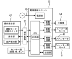
図12は、実施の形態1の除湿機1の制御ブロック図である。本実施の形態1では、電源基板ユニット52と操作基板53とで制御部を構成する。電源基板ユニット52は主制御部としての機能を有する。電源基板ユニット52は、電源コード35が接続される電源部と、CPUと、駆動回路と、記憶部とを有する。CPUは、計時部としてのタイマーを内部に有する。図12に示す例では、圧縮機54、ルーバー33用のモータ、ファンモータ41及びシャッター7用のモータ8に対応させて複数の駆動回路を夫々設けているが、1つの駆動回路を設けて統括して駆動するように構成してもよい。
次に、実施の形態1の除湿機1の動作について説明する。図13は、実施の形態1の除湿機1の動作の一例を示すフローチャート図である。電源コード35をコンセントに接続し、使用者が操作表示部23の運転スイッチをONにすると、上記制御部は、運転モード切替スイッチによって除湿重視運転モードと空気清浄重視運転モードのいずれが選択されているかを判別する(ステップS11)。
除湿重視運転モードが選択されている場合、ステップS12に進み、モータ8を駆動してシャッター7を開位置に回動させることで、第二の風路64を開放する。続いて、ファンモータ41を駆動してシロッコファン42を回転させる(ステップS13)。その後、圧縮機54を駆動する(ステップS14)。これらのステップS12~S14によれば、シロッコファン42によって、吸気口31から湿気を含んだ空気が吸い込まれる。吸気口31から吸い込まれた空気は、第一の風路63に配置されたHEPAフィルタ65、脱臭フィルタ66を通り、熱交換器38へ流れる。これと共に、一部の空気は、解放されている第二の風路64を通り、直接、熱交換器38へ流れる。第二の風路64を通る空気はフィルタ65,66を通らないため、第一の風路63に比べ、圧力損失が小さく、熱交換器38に多くの空気を送ることができる。
熱交換器38の蒸発器38aは、圧縮機54から循環する冷媒によって冷却されているため、湿気を含んだ空気は蒸発器38aで結露して除湿される。除湿された空気は、メイン凝縮器38b及びサブ凝縮器38cで常温に戻された後、スクロール空間45を介して吹出口32から排出される。このとき、ルーバー33用のステップモータを駆動することで、ルーバー33の角度を上下方向で変えることが可能である。これにより、空気を上方向に送風して部屋内に循環気流を発生させて室内を除湿したり、洗濯物に風を当てて乾燥させたりすることができる。
蒸発器38aに結露した水滴は重力によってドレン水受け37に滴下する。その後、排水パイプ37bを通り、貯水タンク26に排水される。貯水タンク26が無い状態、例えば貯水タンク26に溜まったドレン水を捨てている状態では、ドレン水止め37aが排水パイプ37bの排水口を塞いでおり、ドレン水の排水を防止している。また、排水パイプ37bに排水ホースを取り付けた状態ではドレン水は排水ホースを通り、ケース2の外に排水される。
空気清浄重視運転が選択されている場合、ステップS15に進み、モータ8を駆動してシャッター7を閉位置に回動させることで、第二の風路64を閉じる。続いて、ファンモータ41を駆動してシロッコファン42を回転させる(ステップS16)。これによれば、遮蔽壁71が第二の風路64の気流の流れを遮蔽しているため、吸気口31から吸い込まれた空気のほぼ全ては、第一の風路63を通過し、HEPAフィルタ65、脱臭フィルタ66によって清浄化される。このため、吹出口32から送風される空気は、きれいな空気となり、優れた空気清浄機能を発揮する。
ここで、遮蔽壁71の下流側の第二の風路64は、遮蔽壁71の上流側の外気圧に対して負圧となるため、シャッター7には、外気圧と負圧との差圧に応じて、シャッター7を回動させようとする回動力が作用する。本実施の形態によれば、シャッター7の回動軸72a,73aを第二の風路64内に配置すると共に、これらの回動軸72a,73aを遮蔽壁71の左右方向の端部ではなく端部よりも内側、具体的には、遮蔽壁71の垂直二等分線Lv上に配置した。これにより、遮蔽壁71に加わる差圧に起因してシャッター7に作用する回動力Pr1,Pr2が、回動軸72a,73aの左右二方向に分散される。詳細には、遮蔽壁71の左右方向内側部分に加わる差圧は回動力Pr1となり、遮蔽壁71の左右方向外側部分に加わる差圧は回動力Pr2となる。これら回動軸72a,73aまわりに作用する異なる二方向の回動力Pr1,Pr2が左右方向で互いに打ち消し合うことで、モータ8の保持トルクよりも小さく抑えられる。これにより、シャッター7が開方向に動いて隙間が生じることが防止され、隙間からの風漏れが発生することがない。従って、空気清浄性能の低下及び隙間音の発生を防止することができる。なお、上述の如くシャッター7と第二の風路64を画成する壁面62a,61cとの間に不可避的に形成されるクリアランス部分から若干の風漏れが発生するが、隙間音は問題とはならず、シール性能を確保することができる。
また、シャッター7を駆動するステッピングモータ8はシャッター7の上側回動軸72aに連結しているため、例えば、メンテナンスなどで第二の風路64を水拭きした際に水滴がステッピングモータ8にかかることがなく、ステッピングモータ8の水濡れなどによる故障を防止することができる。
実施の形態2.
次に、本発明の実施の形態2について説明する。図14(a)は、実施の形態2による除湿機1をシャッターが閉じた状態で示す横断面図であり、図14(b)は、除湿機1をシャッターが開いた状態で示す横断面図である。図14(a)及び図14(b)では、HEPAフィルタ65及び脱臭フィルタ66の図示を省略している。
次に、本発明の実施の形態2について説明する。図14(a)は、実施の形態2による除湿機1をシャッターが閉じた状態で示す横断面図であり、図14(b)は、除湿機1をシャッターが開いた状態で示す横断面図である。図14(a)及び図14(b)では、HEPAフィルタ65及び脱臭フィルタ66の図示を省略している。
本実施の形態では、回動支点となる回動軸72a,73aが、第二の風路64の左右方向の中間よりも内側に位置している。シャッター7を回転させるスペースは、第二の風路64の内壁である風路仕切り板62の壁面62aから回動軸72a,73aまでの左右方向の距離hと、シャッター7の回動半径Rとの合計となるが、回動軸72a,73aを上記実施の形態1よりも左右方向内側に配置したことで、シャッター7を回転させるスペースを小さくすることができる。この場合、閉位置での遮蔽壁71がHEPAフィルタ65に対して傾斜する姿勢でシャッター7が配置され、シャッター7に作用する回動力の左右のバランスが崩れる虞がある。
本実施の形態では、シャッター7に作用する回動力を左右方向で均等化するために、シャッター7の横断面にて、遮蔽壁71を、屈曲または湾曲する形状に形成している。図14(a)及び図14(b)に示す例では、遮蔽壁71を略「く」の字形状に屈曲させて、遮蔽壁71に加わる回動力Pr1,Pr2を左右方向で均等化するように調整している。また、遮蔽壁71を屈曲または湾曲させることで、遮蔽壁71の長手方向の曲がりに対する強度を向上させることができる。さらに、図14(b)に示すシャッター7が開いた状態では、遮蔽壁71の内側面は第二の風路64の気流の流れに対して凹凸が少なく、第二の風路64の圧力損失をより低減することができる。
実施の形態3.
次に、本発明の実施の形態3について説明する。図15は、実施の形態3による除湿機におけるシャッター7の取付構造を示す縦断面図である。図15は、シャッター7の回動軸72aとステッピングモータ8の回転軸81aとの位置関係を示す。
次に、本発明の実施の形態3について説明する。図15は、実施の形態3による除湿機におけるシャッター7の取付構造を示す縦断面図である。図15は、シャッター7の回動軸72aとステッピングモータ8の回転軸81aとの位置関係を示す。
シャッター7の上方に配置されたステッピングモータ8の回転軸81aは、シャッター7の回動軸72aと左右方向にずらして配置されている。シャッター7の回動軸72aの上端には、ギア72bが外挿されている。ステッピングモータ8の回転軸81aの下端には、ギア72bと噛み合わせられるギア81bが外挿されている。これにより、ステッピングモータ8を駆動すると、ギア72b,81bを介してシャッター7が回動するように構成されている。これによれば、回動軸72aと回転軸81aとが同一線上に配置されていないため、シャッター7の回動軸72a軸方向に動いたとしても、ステッピングモータ8が荷重や衝撃を受けることがないため、ステッピングモータ8の故障を防止することができる。
1 除湿機、 2 ケース(筐体)、 31 吸気口、 32 吹出口、 38 熱交換器(除湿手段)、 4 送風手段、 63 第一の風路、 64 第二の風路、 64a 第二の風路64の入口、 61c,62a 第二の風路64を画成する壁面、 65 HEPAフィルタ(空気清浄化手段、空気清浄化フィルタ)、 66 脱臭フィルタ(空気清浄化手段、空気清浄化フィルタ)、 68 収納空間、 7 シャッター(開閉手段)、 71 遮蔽壁、 71a,71b シール部、 72a 上側回動軸、 73a 下側回動軸、 8 ステッピングモータ(モータ)、 81a 回転軸
Claims (7)
- 吸気口および吹出口を有する筐体と、
前記筐体の内部に配置され、前記吸気口から前記吹出口へ至る気流を発生させる送風手段と、
前記筐体の内部に配置される空気清浄化手段と、
前記筐体の内部に配置され、前記気流の中の水分を除去する除湿手段と、
前記気流が前記空気清浄化手段を通過して前記除湿手段に至る第一の風路と、
前記気流が前記空気清浄化手段を通過せずに前記除湿手段に至る第二の風路と、
前記第二の風路を開閉する開閉手段と、を備え、
前記開閉手段は、前記第二の風路の内部に配置されて上下方向にのびる回動軸を中心に、前記第二の風路を遮蔽する閉位置と前記第二の風路を開放する開位置との間を回動可能なシャッターを有し、前記閉位置での前記シャッターの上下方向に直交する左右方向端部よりも内側に前記回動軸を配置した除湿機。 - 前記空気清浄化手段は空気清浄化フィルタを有し、前記空気清浄化フィルタの左右方向外側に前記第二の風路の入口が設けられ、
前記シャッターは、前記閉位置にて前記第二の風路の入口を塞ぐ上下方向に長手の遮蔽壁を有する請求項1に記載の除湿機。 - 前記シャッターは、前記閉位置での前記遮蔽壁が前記空気清浄化フィルタと平行となる姿勢で配置され、前記シャッターの横断面にて前記遮蔽壁の垂直二等分線上に前記回動軸が設けられる請求項2に記載の除湿機。
- 前記シャッターは、前記閉位置での前記遮蔽壁が前記空気清浄化フィルタに対して傾斜する姿勢で配置され、前記シャッターの横断面にて前記遮蔽壁が屈曲または湾曲する形状に形成されている請求項2に記載の除湿機。
- 前記第一の風路の左右方向両側に夫々第二の風路を画成する壁面を更に備え、
前記シャッターは、前記遮蔽壁の左右方向両端に位置するシール部が前記壁面に近接する閉位置と、前記シール部が前記壁面から離間する開位置との間で回動する請求項2に記載の除湿機。 - 前記第二の風路は前記第二の風路の入口よりも左右方向外側に膨出する収納空間を有し、前記収納空間に前記開位置での前記遮蔽壁が収納される請求項5に記載の除湿機。
- 前記シャッターを回動させるモータを備え、前記モータの回転軸と前記シャッターの前記回動軸とをずらして配置したことを特徴とする請求項1から請求項6のいずれか一項に記載の除湿機。
Priority Applications (3)
| Application Number | Priority Date | Filing Date | Title |
|---|---|---|---|
| JP2024520145A JP7798185B2 (ja) | 2022-05-11 | 2022-05-11 | 除湿機 |
| PCT/JP2022/019960 WO2023218563A1 (ja) | 2022-05-11 | 2022-05-11 | 除湿機 |
| TW111148462A TWI852223B (zh) | 2022-05-11 | 2022-12-16 | 除濕機 |
Applications Claiming Priority (1)
| Application Number | Priority Date | Filing Date | Title |
|---|---|---|---|
| PCT/JP2022/019960 WO2023218563A1 (ja) | 2022-05-11 | 2022-05-11 | 除湿機 |
Publications (1)
| Publication Number | Publication Date |
|---|---|
| WO2023218563A1 true WO2023218563A1 (ja) | 2023-11-16 |
Family
ID=88730040
Family Applications (1)
| Application Number | Title | Priority Date | Filing Date |
|---|---|---|---|
| PCT/JP2022/019960 Ceased WO2023218563A1 (ja) | 2022-05-11 | 2022-05-11 | 除湿機 |
Country Status (3)
| Country | Link |
|---|---|
| JP (1) | JP7798185B2 (ja) |
| TW (1) | TWI852223B (ja) |
| WO (1) | WO2023218563A1 (ja) |
Citations (7)
| Publication number | Priority date | Publication date | Assignee | Title |
|---|---|---|---|---|
| JP2000055424A (ja) * | 1998-08-04 | 2000-02-25 | Sanyo Electric Co Ltd | 空気清浄機 |
| JP2000249394A (ja) * | 1999-02-25 | 2000-09-12 | Sharp Corp | 空気調和機 |
| JP2004131032A (ja) * | 2002-10-15 | 2004-04-30 | Miyagawa Kasei Ind Co Ltd | 空気吹出部構造 |
| JP2004211913A (ja) * | 2002-12-26 | 2004-07-29 | Sanyo Electric Co Ltd | 除湿機 |
| JP2014070776A (ja) * | 2012-09-28 | 2014-04-21 | Fujitsu General Ltd | 空気調和機 |
| JP2014092291A (ja) * | 2012-10-31 | 2014-05-19 | Max Co Ltd | 換気装置 |
| CN106678991A (zh) * | 2017-03-07 | 2017-05-17 | 重庆大学 | 一种适用于辐射空调的新风机组调控系统及其控制方法 |
Family Cites Families (1)
| Publication number | Priority date | Publication date | Assignee | Title |
|---|---|---|---|---|
| JP6563287B2 (ja) | 2015-09-18 | 2019-08-21 | シャープ株式会社 | 除加湿装置 |
-
2022
- 2022-05-11 JP JP2024520145A patent/JP7798185B2/ja active Active
- 2022-05-11 WO PCT/JP2022/019960 patent/WO2023218563A1/ja not_active Ceased
- 2022-12-16 TW TW111148462A patent/TWI852223B/zh active
Patent Citations (7)
| Publication number | Priority date | Publication date | Assignee | Title |
|---|---|---|---|---|
| JP2000055424A (ja) * | 1998-08-04 | 2000-02-25 | Sanyo Electric Co Ltd | 空気清浄機 |
| JP2000249394A (ja) * | 1999-02-25 | 2000-09-12 | Sharp Corp | 空気調和機 |
| JP2004131032A (ja) * | 2002-10-15 | 2004-04-30 | Miyagawa Kasei Ind Co Ltd | 空気吹出部構造 |
| JP2004211913A (ja) * | 2002-12-26 | 2004-07-29 | Sanyo Electric Co Ltd | 除湿機 |
| JP2014070776A (ja) * | 2012-09-28 | 2014-04-21 | Fujitsu General Ltd | 空気調和機 |
| JP2014092291A (ja) * | 2012-10-31 | 2014-05-19 | Max Co Ltd | 換気装置 |
| CN106678991A (zh) * | 2017-03-07 | 2017-05-17 | 重庆大学 | 一种适用于辐射空调的新风机组调控系统及其控制方法 |
Also Published As
| Publication number | Publication date |
|---|---|
| TWI852223B (zh) | 2024-08-11 |
| TW202344783A (zh) | 2023-11-16 |
| JP7798185B2 (ja) | 2026-01-14 |
| JPWO2023218563A1 (ja) | 2023-11-16 |
Similar Documents
| Publication | Publication Date | Title |
|---|---|---|
| JP4624174B2 (ja) | 空気調和機 | |
| KR100917725B1 (ko) | 공기조화기의 실내기 | |
| AU2004248040B2 (en) | Humidity controller apparatus | |
| JP4589133B2 (ja) | 可動パネル開閉機構 | |
| WO2023218563A1 (ja) | 除湿機 | |
| JP6998506B2 (ja) | 空気調和機 | |
| JP5931430B2 (ja) | 空気調和機 | |
| JP2019007653A (ja) | 空気調和機 | |
| JP2007170788A (ja) | 空気調和機 | |
| EP2493277A2 (en) | An improvement in the cooling system for telecommunication shelters | |
| KR20060010086A (ko) | 실내기의 프론트패널 개폐구조 | |
| JP5627355B2 (ja) | 空気調和機 | |
| KR20090022092A (ko) | 공기조화기 | |
| JP3122694B2 (ja) | 空気調和装置の室内ユニット | |
| CN101548137A (zh) | 除湿器 | |
| JP7635884B2 (ja) | 除湿機 | |
| KR100762275B1 (ko) | 공기조화기 | |
| KR100745582B1 (ko) | 공기조화기 | |
| TWI852188B (zh) | 除濕機 | |
| KR100760207B1 (ko) | 공기조화기 | |
| JP4602866B2 (ja) | 空気調和機の室内機 | |
| JP7691327B2 (ja) | フィルタ清掃装置、及び空気調和機 | |
| KR101158581B1 (ko) | 제습기 | |
| KR20090006413A (ko) | 공기조화기 | |
| JP6998505B2 (ja) | 空気調和機 |
Legal Events
| Date | Code | Title | Description |
|---|---|---|---|
| 121 | Ep: the epo has been informed by wipo that ep was designated in this application |
Ref document number: 22941643 Country of ref document: EP Kind code of ref document: A1 |
|
| ENP | Entry into the national phase |
Ref document number: 2024520145 Country of ref document: JP Kind code of ref document: A |
|
| NENP | Non-entry into the national phase |
Ref country code: DE |
|
| 122 | Ep: pct application non-entry in european phase |
Ref document number: 22941643 Country of ref document: EP Kind code of ref document: A1 |