WO2023218521A1 - 工作機械の数値制御装置 - Google Patents
工作機械の数値制御装置 Download PDFInfo
- Publication number
- WO2023218521A1 WO2023218521A1 PCT/JP2022/019788 JP2022019788W WO2023218521A1 WO 2023218521 A1 WO2023218521 A1 WO 2023218521A1 JP 2022019788 W JP2022019788 W JP 2022019788W WO 2023218521 A1 WO2023218521 A1 WO 2023218521A1
- Authority
- WO
- WIPO (PCT)
- Prior art keywords
- cutting
- tool
- workpiece
- motion
- removal area
- Prior art date
- Legal status (The legal status is an assumption and is not a legal conclusion. Google has not performed a legal analysis and makes no representation as to the accuracy of the status listed.)
- Ceased
Links
Images
















Classifications
-
- G—PHYSICS
- G05—CONTROLLING; REGULATING
- G05B—CONTROL OR REGULATING SYSTEMS IN GENERAL; FUNCTIONAL ELEMENTS OF SUCH SYSTEMS; MONITORING OR TESTING ARRANGEMENTS FOR SUCH SYSTEMS OR ELEMENTS
- G05B19/00—Program-control systems
- G05B19/02—Program-control systems electric
- G05B19/18—Numerical control [NC], i.e. automatically operating machines, in particular machine tools, e.g. in a manufacturing environment, so as to execute positioning, movement or co-ordinated operations by means of program data in numerical form
- G05B19/4093—Numerical control [NC], i.e. automatically operating machines, in particular machine tools, e.g. in a manufacturing environment, so as to execute positioning, movement or co-ordinated operations by means of program data in numerical form characterised by part programming, e.g. entry of geometrical information as taken from a technical drawing, combining this with machining and material information to obtain control information, named part program, for the NC machine
-
- G—PHYSICS
- G05—CONTROLLING; REGULATING
- G05B—CONTROL OR REGULATING SYSTEMS IN GENERAL; FUNCTIONAL ELEMENTS OF SUCH SYSTEMS; MONITORING OR TESTING ARRANGEMENTS FOR SUCH SYSTEMS OR ELEMENTS
- G05B19/00—Program-control systems
- G05B19/02—Program-control systems electric
- G05B19/18—Numerical control [NC], i.e. automatically operating machines, in particular machine tools, e.g. in a manufacturing environment, so as to execute positioning, movement or co-ordinated operations by means of program data in numerical form
- G05B19/4093—Numerical control [NC], i.e. automatically operating machines, in particular machine tools, e.g. in a manufacturing environment, so as to execute positioning, movement or co-ordinated operations by means of program data in numerical form characterised by part programming, e.g. entry of geometrical information as taken from a technical drawing, combining this with machining and material information to obtain control information, named part program, for the NC machine
- G05B19/40931—Numerical control [NC], i.e. automatically operating machines, in particular machine tools, e.g. in a manufacturing environment, so as to execute positioning, movement or co-ordinated operations by means of program data in numerical form characterised by part programming, e.g. entry of geometrical information as taken from a technical drawing, combining this with machining and material information to obtain control information, named part program, for the NC machine concerning programming of geometry
- G05B19/40932—Shape input
-
- G—PHYSICS
- G05—CONTROLLING; REGULATING
- G05B—CONTROL OR REGULATING SYSTEMS IN GENERAL; FUNCTIONAL ELEMENTS OF SUCH SYSTEMS; MONITORING OR TESTING ARRANGEMENTS FOR SUCH SYSTEMS OR ELEMENTS
- G05B19/00—Program-control systems
- G05B19/02—Program-control systems electric
- G05B19/18—Numerical control [NC], i.e. automatically operating machines, in particular machine tools, e.g. in a manufacturing environment, so as to execute positioning, movement or co-ordinated operations by means of program data in numerical form
- G05B19/182—Numerical control [NC], i.e. automatically operating machines, in particular machine tools, e.g. in a manufacturing environment, so as to execute positioning, movement or co-ordinated operations by means of program data in numerical form characterised by the machine tool function, e.g. thread cutting, cam making, tool direction control
Definitions
- the present invention relates to a numerical control device for a machine tool.
- a numerical control device for a machine tool of the present disclosure is to relatively rotate the tool and the workpiece while relatively reciprocating the tool and the workpiece to perform a cutting operation in the forward direction and a cutting operation in the backward direction.
- a numerical control device for a machine tool that performs cutting of the workpiece by both a removal area input unit that analyzes the cutting program and reads the shape of a removal area of the workpiece that is removed by the cutting process; , a machining condition input unit that reads machining conditions for the cutting process including at least the depth of cut of the tool in the forward direction cutting operation and the depth of cut of the tool in the backward direction cutting operation; Based on machining conditions, the tool intersects an uncut portion of the removal area, and the amount of intersection does not exceed the depth of cut in the forward direction and the depth of cut in the backward direction under the machining conditions.
- a motion generating section that generates the cutting motion in the forward direction and the cutting motion in the backward direction.
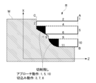
- FIG. 1 is a diagram showing an example of a numerical control device for a machine tool according to the present embodiment. This is an example of a machining program that performs cutting of arbitrary shapes including straight and curved contours. It is an example of explanation of the machining program shown in FIG. 2A.
- 2A is a cross-sectional view showing the shape of a removal area shown by the processing program shown in FIG. 2A and a part of the contour shape of the workpiece after processing (the upper half of the rotation axis Z).
- FIG. 2A is a cross-sectional view showing the shape of a removal area shown by the processing program shown in FIG. 2A and a part of the contour shape of the workpiece after processing (the upper half of the rotation axis Z).
- FIG. 1 is a diagram showing an example of a numerical control device for a machine tool according to the present embodiment. This is an example of a machining program that performs cutting of arbitrary shapes including straight and curved contours. It is an example of explanation of the machining program shown
- FIG. 7 is a diagram illustrating an example of a cutting operation in the forward direction and a backward cutting operation of the tool by the motion generation unit.
- FIG. 7 is a diagram illustrating an example of a cutting operation in the forward direction and a backward cutting operation of the tool by the motion generation unit.
- FIG. 7 is a diagram illustrating an example of a cutting operation in the forward direction and a backward cutting operation of the tool by the motion generation unit.
- FIG. 7 is a diagram illustrating an example of an approach motion by a motion generation unit.
- FIG. 7 is a diagram illustrating an example of an approach motion by a motion generation unit.
- FIG. 7 is a diagram illustrating an example of a switching operation between a cutting operation in the forward direction and a cutting operation in the backward direction by the motion generation unit.
- FIG. 7 is a diagram illustrating an example of a switching operation between a cutting operation in the forward direction and a cutting operation in the backward direction by the motion generation unit.
- FIG. 6 is a diagram illustrating an example of a rounding-up operation along a removal area by a motion generation unit.
- FIG. 6 is a diagram illustrating an example of a rounding-up operation along a removal area by a motion generation unit.
- FIG. 6 is a diagram showing an example of an escape motion and an approach motion after the round-up motion by the motion generation unit.
- FIG. 7 is a diagram showing an example of a round-up motion and a cutting motion by a motion generation unit.
- FIG. 7 is a diagram showing an example of a round-up motion and a cutting motion by a motion generation unit. It is a figure which shows an example of the escape motion and approach motion at the time of the completion
- FIG. 13A is a cross-sectional view showing the shape of a removal area shown by the processing program shown in FIG.
- FIG. 13A is a cross-sectional view showing the shape of a removal area shown by the processing program shown in FIG. 13A and a part of the contour shape of the workpiece after processing (the upper half of the rotation axis Z).
- FIG. 13A is a cross-sectional view showing the shape of a removal area shown by the processing program shown in FIG. 13A and a part of the contour shape of the workpiece after processing (the upper half of the rotation axis Z).
- FIG. 13B is a cross-sectional view showing the shape of a removal area shown by the processing program shown in FIG.
- FIG. 13C is a cross-sectional view showing the shape of a removal area shown by the processing program shown in FIG. 13C and a part of the contour shape of the workpiece after processing (the upper half of the rotation axis Z). It is a figure which shows an example of the cutting operation
- FIG. 1 is a diagram showing an example of a numerical control device for a machine tool according to the present embodiment.
- the numerical control device 10 shown in FIG. 1 controls the operation of the machine tool 20, specifically the cutting operation of the workpiece W by the tool T, based on the machining program 5.
- Examples of the workpiece W include a columnar, cylindrical, conical, or truncated conical workpiece.
- the central axis of the workpiece W which is the rotational axis of the workpiece W, is the Z-axis, and the axis perpendicular to the Z-axis is the X-axis.
- the machine tool 20 uses the tool T to cut the workpiece W. Specifically, the machine tool 20 rotates the workpiece W using the Z-axis as a rotation axis, while reciprocating the tool T along the Z-axis or along the composite direction of the Z-axis and the X-axis. Cutting process is carried out.
- the machine tool 20 performs a cutting process on the workpiece W by both a cutting operation in the forward direction (for example, ⁇ Z direction) and a cutting operation in the backward direction (for example, the +Z direction).
- An example of such a tool T is a tool having two blades T1 and T2.
- the machine tool 20 is not limited to a linear shape in the direction along the Z-axis, and can also process a workpiece having an arc shape. Moreover, the machine tool 20 is not limited to machining the outer circumferential surface of a workpiece, but can also process the inner circumferential surface of a cylindrical workpiece.
- the numerical control device 10 controls the rotation operation of the workpiece W and also controls the movement operation of the cutting edge T3 of the tool T. Below, control of the moving operation of the cutting edge T3 of the tool T will be explained in detail.
- the numerical control device 10 includes a removal area input section 12, a processing condition input section 14, a motion generation section 16, and a storage section 18.
- the numerical control device 10 (excluding the storage unit 18) is composed of an arithmetic processor such as a CPU (Central Processing Unit), a DSP (Digital Signal Processor), and an FPGA (Field-Programmable Gate Array).
- Various functions of the numerical control device 10 (excluding the storage section 18) are realized by, for example, executing predetermined software (programs) stored in the storage section 18.
- Various functions of the numerical control device 10 may be realized by cooperation between hardware and software, or may be realized only by hardware (electronic circuit).
- the storage unit 18 is composed of a memory such as a ROM (Read Only Memory), an HDD (Hard Disk Drive), or an SSD (Solid State Drive).
- the storage unit 18 stores predetermined software (programs) for executing various functions of the numerical control device 10 described above.
- the machining program 5 includes the shape of the removal area of the work W to be removed by cutting (in other words, the contour shape of the work W after cutting) and the machining conditions of the cutting.
- the removal area input unit 12 analyzes the machining program 5 and reads the shape of the removal area of the workpiece W.
- the machining condition input unit 14 analyzes the machining program 5 and reads machining conditions for cutting. Below, the machining program 5, removal area input section 12, and machining condition input section 14 will be explained in detail.
- FIG. 2A is an example of a machining program that performs cutting of an arbitrary shape including straight and curved contours
- FIG. 2B is an example of an explanation of the machining program shown in FIG. 2A
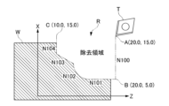
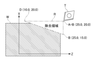
- FIGS. 3A and 3B are cross-sectional views showing the shape of the removal area shown by the processing program shown in FIG. 2A and a part of the contour shape of the workpiece after processing (the upper half of the rotation axis Z).
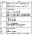
- G130 is a command to generate a reciprocating cutting operation parallel to the Z axis by specifying a plurality of moving blocks N100 to N104.
- PS_ is the first sequence number of the moving block (moving block N100 from A ⁇ B).
- PE_ is the last sequence number of the moving block (moving block N104 of ⁇ C).
- U_ is a finishing allowance for finishing machining, and is a finishing allowance in the X direction.
- W_ is a finishing allowance for finishing processing, and is a finishing allowance in the Z direction.
- G00 is a positioning command.
- G01 is a command for cutting feed by linear interpolation.
- G02 is a command for cutting feed by clockwise circular interpolation (R specifies the radius of the circular arc).
- the movement blocks N100 to N104 indicate the contour shape of the removal region R of the workpiece W specified by one or more lines among straight lines or curved lines, in other words, the contour shape of the workpiece W after cutting.
- the moving blocks N100 to N104 indicate the contour shape of the removal area R of the workpiece W in the finished shape, in other words, the contour shape of the workpiece W after cutting.
- the machining program includes the contour shape of the removal region R of the work W to be removed by cutting, in other words, the contour shape of the work W after cutting.
- the removal area input unit 12 analyzes the machining program and reads the shape of the removal area R of the work W to be removed by cutting from the contour shape of the removal area in the machining program. For example, in the case of the G130 command shown in FIGS. 2A and 3A, the removal area input unit 12 reads the inside of the area surrounded by points ABC from the moving blocks N100 to N104 as the removal area R. Alternatively, as shown in FIGS. 2A and 3B, when the finishing allowance (U, W) is specified, the removal area input unit 12 further reads the finishing allowance (U, W) from the machining program and adds the read removal area to the finishing allowance (U, W). Move R in parallel in the X and Z directions by the finishing allowance.
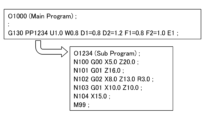
- FIG. 4A is an example of a machining program that performs cutting of an arbitrary shape including straight and curved contours
- FIG. 4B is an example of an explanation of the machining program shown in FIG. 4A.
- movement blocks N100 to N104 may be provided as subprograms.
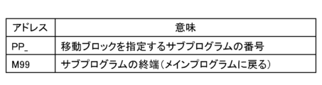
- PP_ is the number of a subprogram that specifies a moving block (finished shape).
- M99 indicates the end of the subprogram (return to the main program).
- the machining program includes machining conditions for cutting.
- D1_ is the depth of cut of the tool T in the cutting operation in the forward direction (A ⁇ C direction)
- D2_ is the depth of cut of the tool T in the cutting operation in the backward direction (C ⁇ A direction).
- F1_ is the feed rate of the tool T in the cutting operation in the forward direction (A ⁇ C direction)
- F2_ is the feed rate of the tool T in the cutting operation in the return direction (C ⁇ A direction).
- E_ is the cutting direction at the end of machining. For example, in the case of E0, there is no designation of the cutting direction at the end of machining. For example, in the case of E1, the cutting direction at the end of machining is designated as the forward direction.
- the cutting direction at the end of machining is designated as the return direction.
- RR_ is the escape amount of the tool T after the cutting operation.
- TY_ is a designation of a cut-up operation or a cut-in operation in a cutting operation.
- a rounding operation or a cutting operation along the outer periphery of the removal region R is specified.
- a round-up operation or a cut-in operation using a line segment is specified.
- UD_ is the empty amount of the round-up operation.
- the machining condition input unit 14 analyzes the machining program and reads the machining conditions for cutting. For example, in the case of the G130 command shown in FIG. 2A, the machining condition input unit 14 reads the cutting amount of the tool T in the forward cutting operation from the address D1, and reads the cutting amount of the tool T in the backward cutting operation from the address D2. Read the amount. Further, the machining condition input unit 14 reads the feed rate of the tool T in the cutting operation in the forward direction from the address F1, and reads the feed rate of the tool T in the cutting operation in the backward direction from the address F2. Further, the machining condition input unit 14 reads the cutting direction at the end of machining from the address E.
- the machining condition input unit 14 reads the escape amount of the tool T after the cutting operation from the address RR. Further, the machining condition input unit 14 reads the designation of the cut-up operation or the cut-in operation in the cutting operation and the type of path from the address TY. For example, in the case of TY0, the machining condition input unit 14 reads a rounding-up operation or a cutting-in operation on a straight path or a curved path along the outer periphery of the removal region R. For example, in the case of TY1, the machining condition input unit 14 reads a rounding-up operation or a cutting-in operation along an arbitrary straight line path (line segment) on the plane formed by the Z-axis and the X-axis.
- the machining condition input unit 14 reads a rounding-up operation or a cutting-in operation according to an arbitrary curved path (arc) on the plane formed by the Z-axis and the X-axis. Further, the machining condition input unit 14 reads the empty amount of the round-up operation from the address UD.
- FIG. 5A is an example of a machining program that performs cutting of an arbitrary shape including straight and curved contours
- FIG. 5B is an example of a table of tool identification information and its machining conditions.
- the storage unit 18 stores in advance information in which tool identification information and its machining conditions (D1, D2, F1, F2, E, TY, UD) are associated in a table format.
- the machining program 5 includes designation T_ of tool identification information.
- the machining condition input unit 14 may analyze the machining program and read the machining conditions corresponding to the tool identification information from the storage unit 18. Thereby, the machining program 5 can be simplified.
- the motion generation section 16 generates a reciprocating cutting motion based on the removal region read by the removal region input section 12 and the processing conditions read by the processing condition input section 14 . Specifically, the motion generation unit 16 generates the cutting amount of the tool in the forward direction and the cutting depth of the tool in the backward direction so that the tool T intersects with the uncut portion of the removal region R, and the amount of intersection is the cutting amount of the tool in the forward direction and the cutting depth of the tool in the backward direction according to the machining conditions.
- the cutting motion of the tool T in the forward direction and the backward direction with respect to the workpiece W is generated so as not to exceed the amount.
- the cutting operation in the forward direction and the cutting operation in the backward direction are straight paths parallel to the Z-axis, and paths in mutually opposite directions in the Z-axis direction.
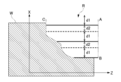
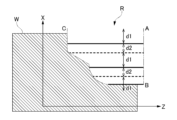
- FIGS. 6A to 6C are diagrams showing an example of a cutting operation in the forward direction and a cutting operation in the backward direction of the tool by the motion generation unit.
- the cutting operation in the forward direction is shown by a solid line
- the cutting movement in the backward direction is shown by a broken line
- the depth of cut in the cutting movement in the forward direction is shown as d1
- the depth of cut in the cutting movement in the backward direction is shown as d2.
- the motion generation unit 16 sequentially creates the forward direction cutting motion (solid line) and the backward direction cutting.
- the operations are alternately generated with a depth of cut d1 of the cutting operation in the forward direction and a depth of cut d2 of the cutting operation in the backward direction.
- the motion generation unit 16 sequentially generates the cutting motion in the backward direction (broken line) and the forward direction.
- Cutting operations are alternately generated with a depth of cut d2 of the cutting operation in the backward direction and a depth of cut d1 of the cutting operation in the forward direction.
- the motion generation unit 16 if there is no designation (E) of the cutting direction at the end of machining, the motion generation unit 16 generates a cutting motion in the forward direction (solid line) and a cutting motion in the backward direction (broken line) in order from the top. ) may be generated alternately using the cutting depth d1 of the forward cutting operation and the cutting depth d2 of the backward cutting operation.
- the operation generation unit 16 ends the creation of the cutting operation.
- the motion generation unit 16 adjusts the depth of cut of the last generated cutting motion so that it does not exceed the removal region R. Note that when the depth of cut of the cutting operation exceeds the removal area R, the motion generation unit 16 may be arranged to divide the excess amount and allocate it to multiple cutting operations, and subtract it from the depth of cut of the multiple cutting operations. good.
- FIGS. 7A and 7B are diagrams illustrating an example of approach motion by the motion generation unit.
- the approach operation is not necessary.
- the motion generation unit 16 An approach motion (positioning motion, rapid forward motion) in the Z direction may be generated from the processing start point A to the intersection point.
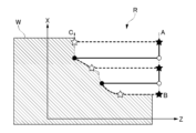
- FIGS. 8A and 8B are diagrams illustrating an example of a switching operation between a cutting operation in the forward direction and a cutting operation in the backward direction by the motion generation unit.
- the starting position of the forward cutting operation (solid line) is indicated by a white circle
- the end position of the forward direction cutting operation (solid line) is indicated by a black circle.
- the start position of the cutting operation in the backward direction is indicated by a white star
- the end position of the cutting operation in the backward direction is indicated by a black star. show.
- the motion generation unit 16 removes the material toward the start position (white circle) of the forward cutting motion (solid line) or the start position (white star) of the backward cutting motion (broken line).
- An approach motion or cutting motion along the outer periphery of region R is generated. Further, the motion generation unit 16 generates the outer periphery of the removal region R so as to connect the end position (black circle) of the adjacent forward cutting motion (solid line) and the start position (white star) of the backward cutting motion (broken line).
- the motion generation unit 16 generates the outer periphery of the removal region R so as to connect the end position (black star) of the adjacent backward cutting motion (broken line) and the start position (white circle) of the forward cutting motion (solid line). generate an approach or cutting motion along the Note that the cutting operation is an operation in which the tool T approaches the uncut portion of the removal region R.
- the motion along A ⁇ B may be an approach motion (positioning motion, fast-forward motion).
- the operation along A to B may be a cutting operation (cutting feed operation).
- the operation along B ⁇ C may be a cutting operation (cutting feed operation).
- FIGS. 9A and 9B are diagrams illustrating an example of a rounding-up operation along a removal area by the operation generation unit.
- the motion generation unit 16 generates a cutting motion around the outer periphery of the removal area R in the forward cutting motion (solid line) and the backward cutting motion (broken line). It may also include a rounding-up operation (TY) along.
- the cutting-up operation is an operation in which the tool T moves away from the uncut portion of the removal region R.
- the rounding-up operation may include a passing operation (UD) along the outer periphery of the removal region R.
- the idle operation is an operation in which the tool T reaches the uncut portion of the removal region R and then further exceeds the uncut portion. In this case, the cutting operation is performed again by the reverse operation of the cutting-up operation.
- FIG. 10 is a diagram illustrating an example of an escape motion and an approach motion after the round-up motion by the motion generation unit.
- the motion generation unit 16 may include a escape motion (RR) and an approach motion after the round-up motion.
- the escape motion is a motion in which the tool T moves away from the workpiece W. Thereby, interference between the tool T and the workpiece W can be suppressed. Further, it is possible to prevent cutter marks from being formed on the workpiece W.
- FIGS. 11A and 11B are diagrams illustrating an example of a rounding-up motion and a cutting-in motion by the motion generation unit.
- the motion generation unit 16 generates an arbitrary linear path (line segment) in the plane formed by the Z-axis and the X-axis for the cutting motion in the forward direction (solid line) and the cutting motion in the backward direction (broken line). It may include a cutting operation and a cutting-up operation (TY).
- the motion generation unit 16 generates an arbitrary curved path (circular arc) in the plane formed by the Z-axis and the X-axis for the forward cutting motion (solid line) and the backward cutting motion (broken line).
- the cutting load on the tool during the cutting operation can be reduced.
- the motion generation unit 16 may include a escape motion (RR) and an approach motion after the round-up motion.
- RR escape motion
- FIGS. 12A and 12B are diagrams illustrating an example of an escape motion and an approach motion at the end of machining by the motion generation unit.
- the motion generation unit 16 when the depth of cut of the cutting operation exceeds the removal area R, in other words, when the tool does not intersect with the uncut part of the removal area, the motion generation unit 16 generates a escape movement (RR ) and approach movements may be generated.
- the motion generation unit 16 may generate escape motions a, b, and c after the machining motion is completed.
- the motion generation unit 16 may generate escape motions a, b, and c after the round-up motion.
- the escape motion a is, for example, cutting feed.
- the escape motions b and c are, for example, fast forwarding back to the motion starting point A.
- the machining program only needs to specify the shape of the removal area, in other words, the shape after machining, and from this machining program, the cutting operation in the forward direction and the cutting operation in the backward direction can be performed. It is possible to generate the position or the amount of movement of the cutting operation in the forward direction and the cutting operation in the return direction, taking into consideration the respective depths of cut of the cutting operations. This allows the numerical control device to perform both forward and backward cutting operations without using relatively effective programming support software such as CAM, while reducing the cost of introducing programming support software. can be generated.
- the configuration of the numerical control device according to the second embodiment is similar to the configuration of the numerical control device according to the first embodiment shown in FIG. Compared to the numerical control device according to the first embodiment shown in FIG. different.
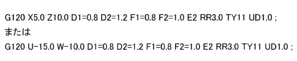
- FIG. 13A is an example of a processing program for cutting a shape that includes only a straight line outline, in other words, a rectangular removal area
- FIG. 13B shows a shape that includes only a straight line outline, in other words, a rectangular shape
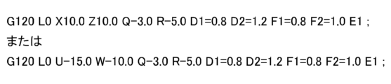
- FIG. 13C is an example of a machining program for cutting a removal area that includes a tapered shape (right triangular shape)
- FIG. 13D is an example of an explanation of the processing program shown in FIGS. 13A to 13C.
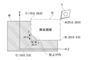
- FIGS. 14A to 14C are cross-sectional views showing the shape of the removal area indicated by the machining program shown in FIG. 13A and a part of the contour shape of the workpiece after machining (the upper half of the rotation axis Z), and FIG.
- FIG. 14D is
- FIG. 14E is a sectional view showing the shape of the removal area shown by the machining program shown in FIG. 13B and a part of the contour shape of the workpiece after machining (the upper half of the rotation axis Z)
- FIG. 14E is a sectional view showing the shape of the removal area shown by the machining program shown in FIG.
- FIG. 3 is a cross-sectional view showing the shape of the removed region shown in FIG.
- G120 is a command to generate a reciprocating cutting operation parallel to the Z axis by specifying a rectangular area.
- X_ is the X-axis coordinate value (position) of point D located diagonally to the operation start point A
- Z_ is the Z-axis coordinate value (position) of point D.
- U_ is the amount of change (movement) in the X-axis direction from operation start point A to point D (in other words, point B)
- W_ is the amount of change (movement amount) from operation start point A to point D (in other words, point C). is the amount of change (amount of movement) in the Z-axis direction.
- the X-axis coordinate value and Z-axis coordinate value of the operation start point A can be determined from the pre-stored shape of the workpiece W before machining.
- the machining program includes the outline shape (rectangular shape) of the removal area R of the workpiece W to be removed by the cutting process, in other words, the outline shape of the workpiece W after the cutting process.
- the removal area input unit 12 analyzes the machining program and reads the shape of the removal area R of the work W to be removed by cutting from the contour shape (rectangular shape) of the removal area in the machining program. For example, in the case of the G120 command shown in FIGS. 13A and 14A, the removal area input unit 12 inputs the position (X, Z) of point D located diagonally to operation start point A or the movement of operation start point A to point D. From the amounts (U, W), the inside of the rectangular shape ABDC is read as the removal area R. The position of the operation start point A can be determined from the pre-stored shape of the workpiece W before cutting.
- the machining program may include a finishing allowance for finishing machining.
- the address TY for designating the rounding-up operation or the cutting-in operation includes the designation of the finishing allowance.
- the removal area input unit 12 may further read the finishing allowance (TY) from the machining program so that the finishing allowance is not included in the removal area.
- the finishing allowance For example, in the case of the G120 command shown in FIG. 13A, FIG. 14B, and FIG.
- the area surrounded by the figure with three points as vertices is defined as the finishing allowance.
- the predetermined distance d is the command value for the depth of cut D1 in the forward cutting operation
- the predetermined distance d is the command value for the cutting depth D1 in the backward direction. This is the command value for the depth of cut D2 in the cutting operation.
- the shape of the finishing allowance is set inside the triangular shape DEF as shown in FIG. 14B.
- the shape of the finishing allowance is defined as an area surrounded by the line segments DE, DF and the arc EF, as shown in FIG. 14C.
- the processing program may include a contour shape of the removal region R specified as a rectangular shape with a tapered shape (right triangle shape).
- Q_ is the amount of taper in the X direction from point B
- R_ is the amount of taper in the Z direction from point C.
- the removal area input unit 12 analyzes the machining program and determines the removal area R of the workpiece W to be removed by cutting based on the outline shape (rectangular shape and right triangle taper shape) of the removal area in the machining program. Read the shape. For example, in the case of the G120 command shown in FIGS. 13B and 14D, the removal area input unit 12 inputs the position (X, Z) of the point D located diagonally to the operation start point A or the operation start point A, as described above. - From the movement amount (U, W) of point D, read the inside of the rectangular shape ABDC as the removal area R.
- the removal area input unit 12 reads the inside of the right triangle shape B-B'-D as the removal area R from the address (Q) regarding the amount of change in the X-axis direction from point B to point B'. Further, the removal area input unit 12 reads the inside of the right triangle C-C'-D as the removal area R from the address (R) regarding the amount of change in the Z-axis direction from point C to point C'.
- the removal area input unit 12 merges the inside of the rectangular shape ABDC, the inside of the right triangle shape BB'-D, and the inside of the right triangle shape CC'-D.
- the removed area is read as the removed area R.
- the machining program may include the contour shape of the removal region R specified only in a tapered shape (right triangular shape).
- the removal area input unit 12 analyzes the machining program and reads the shape of the removal area R of the workpiece W to be removed by cutting from the outline shape (tapered right triangle shape) of the removal area in the machining program. .
- the inside of BB'-D is read as the removal area R.
- the machining program includes machining conditions (D1, D2, F1, F2, E, RR, UD) for cutting, as described above.
- the machining condition input unit 14 analyzes the machining program and reads the machining conditions (D1, D2, F1, F2, E, RR, UD) for cutting, as described above. Then, as described above, the motion generation section 16 generates a reciprocating cutting motion based on the removal region read by the removal region input section 12 and the processing conditions read by the processing condition input section 14.
- the motion generation unit 16 generates the cutting amount of the tool in the forward direction and the cutting depth of the tool in the backward direction so that the tool T intersects with the uncut portion of the removal region R, and the amount of intersection is the cutting amount of the tool in the forward direction and the cutting depth of the tool in the backward direction according to the machining conditions.
- the cutting motion of the tool T in the forward direction and the backward direction with respect to the workpiece W is generated so as not to exceed the amount.
- the numerical control device of the second embodiment also provides the same advantages as the numerical control device of the first embodiment.
- the cutting motion in the forward direction and the cutting motion in the backward direction generated by the motion generation unit 16 are linear paths parallel to the rotation axis (Z-axis) of the work W, and the rotation of the work W The paths were in opposite directions to each other in the direction along the axis (Z-axis).
- the present invention is not limited thereto.
- the cutting motion in the forward direction and the cutting motion in the backward direction generated by the motion generation unit 16 are performed in the plane formed by the rotational axis (Z-axis) of the workpiece W and the orthogonal axis (X-axis) orthogonal to this rotational axis.
- the paths may be arbitrary straight paths, parallel to each other, and opposite to each other in the direction along the rotation axis (Z-axis) of the workpiece W.
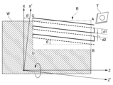
- the cutting operation in the forward direction and the cutting operation in the backward direction are diagonal paths with an inclination angle ⁇ (0° ⁇ 90°) with respect to the Z axis. Good too.
- the starting point for creating a path for the cutting operation may be the point (point D in the example of FIG. 15) farthest from point A in the X' axis (coordinate axis obtained by rotating the X axis clockwise by ⁇ ).
- the cutting operation in the forward direction and the cutting operation in the backward direction are arbitrary curved paths in the plane formed by the rotational axis (Z-axis) of the workpiece W and the orthogonal axis (X-axis) perpendicular to this rotational axis.
- the paths may be parallel to each other, and the paths may be in opposite directions in the direction along the rotation axis (Z-axis) of the workpiece W.
- the cutting operation in the forward direction and the cutting operation in the backward direction may be along a concentric circle with respect to point A. in this case, - Find the intersection between the circular arc centered on point A and the outer periphery of the removal area, and use that as the starting point/end point of the outgoing and returning paths.
- the present invention is not limited to this, and is also applicable to a form in which a workpiece is moved back and forth with respect to a tool. That is, the present invention is applicable to a configuration in which a tool and a workpiece are relatively moved back and forth. In this case, the movement of the tool may be replaced with relative reciprocating movement of the tool and the workpiece.
- the workpiece is rotated.
- the present invention is not limited to this, and can also be applied to a form in which the tool is rotated with respect to the work. That is, the present invention is applicable to a configuration in which a tool and a workpiece are rotated relative to each other.
- the rotation of the workpiece may be replaced with relative rotation of the tool and the workpiece.
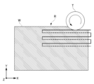
- FIG. 17 is a diagram seen from the +Z direction (directly above).
- the cutting operation in the forward direction solid line
- -X direction is a cutting operation in a down cut (-X direction)
- the cutting operation in the backward direction is a cutting operation in an up cut (+X direction).
- the machining program removes the workpiece W specified by five straight lines and curves (five movement blocks N100 to N104).
- a form including the outline shape of the region R is illustrated.
- the present invention is not limited thereto, and the machining program may include a contour shape of the removal area R of the workpiece W specified by one or more lines selected from a straight line or a curved line.
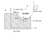
- the machining program may include the contour shape of the removal region R of the workpiece W specified by only one curve (one movement block N200). Note that in FIG.
- the moving block N200 specifies A ⁇ B ⁇ C in one circular arc (point B is the lowest point of the circular arc).
Landscapes
- Engineering & Computer Science (AREA)
- Physics & Mathematics (AREA)
- Human Computer Interaction (AREA)
- Manufacturing & Machinery (AREA)
- General Physics & Mathematics (AREA)
- Automation & Control Theory (AREA)
- Geometry (AREA)
- Numerical Control (AREA)
Abstract
Description
図1は、本実施形態に係る工作機械の数値制御装置の一例を示す図である。図1に示す数値制御装置10は、加工プログラム5に基づいて、工作機械20の動作、具体的には工具TによるワークWの切削加工動作を制御する。
G130は、複数の移動ブロックN100~N104の指定により、Z軸に平行な往復切削動作を生成する指令である。
PS_は、移動ブロックの最初のシーケンス番号(A→Bの移動ブロックN100)である。
PE_は、移動ブロックの最後のシーケンス番号(→Cの移動ブロックN104)である。
U_は、仕上げ加工のための仕上げ代であって、X方向の仕上げ代である。
W_は、仕上げ加工のための仕上げ代であって、Z方向の仕上げ代である。
G00は、位置決めの指令である。
G01は、直線補間による切削送りの指令である。
G02は、時計回りの円弧補間による切削送り(Rで円弧の半径を指定)の指令である。
移動ブロックN100は、移動開始点A(Z=20.0,X=15.0)から点B(Z=20.0,X=5.0)への位置決めの移動を示し、
移動ブロックN101は、点B(Z=20.0,X=5.0)からZ方向の位置Z=16.0への直線補間による切削送りの移動を示し、
移動ブロックN102は、更に、Z方向の位置Z=13.0への円弧半径R=3.0での時計回りの円弧補間による切削送りの移動を示し、
移動ブロックN103は、更に、位置(Z=10.0,X=10.0)への直線補間による切削送りの移動を示し、
移動ブロックN104は、更に、X方向の位置X=15.0、すなわち移動終了点C(Z=10.0,X=15.0)への直線補間による切削送りの移動を示す。
なお、B-C間では、X軸の座標値が減少することはないものとする。
PP_は、移動ブロック(仕上げ形状)を指定するサブプログラムの番号である。
M99は、サブプログラムの終端(メインプログラムに戻る)を示す。
D1_は、往路方向(A→C方向)の切削動作における工具Tの切込み量であり、D2_は、復路方向(C→A方向)の切削動作における工具Tの切込み量である。
F1_は、往路方向(A→C方向)の切削動作における工具Tの送り速度であり、F2_は、復路方向(C→A方向)の切削動作における工具Tの送り速度である。
E_は、加工終了時の切削方向である。例えばE0の場合、加工終了時の切削方向の指定はない。例えばE1の場合、加工終了時の切削方向を往路方向と指定する。また、例えばE2の場合、加工終了時の切削方向を復路方向と指定する。
RR_は、切削動作後の工具Tの逃げ量である。
TY_は、切削動作における切上げ動作または切込み動作の指定である。例えばTY0の場合、除去領域Rの外周に沿った切上げ動作または切込み動作を指定する。例えばTY1の場合、線分による切上げ動作または切込み動作を指定する。また、例えばTY2の場合、円弧による切上げ動作または切込み動作を指定する。
UD_は、切上げ動作の空過量である。
上述した第1実施形態では、直線および曲線の輪郭を含む任意の形状の切削加工について説明した。第2実施形態では、直線の輪郭のみを含む形状、換言すれば矩形形状の除去領域、矩形形状にテーパ形状(直角三角形状)を含む除去領域、またはテーパ形状(直角三角形状)の除去領域、の切削加工について説明する。
G120は、矩形領域の指定により、Z軸に平行な往復切削動作を生成する指令である。
X_は、動作開始点Aの対角に位置する点DのX軸座標値(位置)であり、Z_は、D点のZ軸座標値(位置)である。
U_は、動作開始点Aから点D(換言すれば点B)へのX軸方向の変化量(移動量)であり、W_は、動作開始点Aから点D(換言すれば点C)へのZ軸方向の変化量(移動量)である。
なお、動作開始点AのX軸座標値およびZ軸座標値は、予め記憶している加工前のワークWの形状からわかる。
このように、加工プログラムは、切削加工によって除去されるワークWの除去領域Rの輪郭形状(矩形形状)、換言すれば切削加工後のワークWの輪郭形状、を含む。
Q_は、点BからのX方向のテーパ量であり、R_は、点CからのZ方向のテーパ量である。
具体的には、図15に示すように、往路方向の切削動作および復路方向の切削動作は、Z軸に対して傾斜角度θ(0°<θ<90°)の斜め方向の経路であってもよい。
この場合、
・Z-X平面を時計回りにθだけ回転させ、切込み量d1,d2をそれぞれd1cosθ,d2cosθに置き換えれば、上述した第2実施形態と同様に考えることができる。
・切削動作の経路作成の起点は点AからX’軸(X軸を時計回りにθ回転した座標軸)方向に最も離れた点(図15の例では点D)とすればよい。
具体的には、図16に示すように、往路方向の切削動作および復路方向の切削動作は、点Aに対して同心円に沿った経路であってもよい。
この場合、
・点Aを中心とする円弧と除去領域の外周との交点を求め、それを往路と復路の起点/終点とすればよい。
10 数値制御装置
12 除去領域入力部
14 加工条件入力部
16 動作生成部
18 記憶部
20 工作機械
T 工具
W ワーク
Claims (13)
- 工具およびワークを相対的に回転させつつ、前記工具および前記ワークを相対的に往復移動させて、往路方向の切削動作および復路方向の切削動作の両方により前記ワークの切削加工を行う工作機械の数値制御装置であって、
前記切削加工のプログラムを解析し、前記切削加工によって除去される前記ワークの除去領域の形状を読み取る除去領域入力部と、
少なくとも前記往路方向の切削動作における前記工具の切込み量および前記復路方向の切削動作における前記工具の切込み量を含む前記切削加工の加工条件を読み取る加工条件入力部と、
前記除去領域の形状および前記加工条件に基づいて、前記工具が前記除去領域のうち未切削部分と交叉するように、かつ、交叉量が前記加工条件における前記往路方向の切込み量および前記復路方向の切込み量を越えないように、前記往路方向の切削動作および前記復路方向の切削動作を生成する動作生成部と、
を備える、
工作機械の数値制御装置。 - 前記動作生成部によって生成される前記往路方向の切削動作および前記復路方向の切削動作は、
前記ワークの回転軸と平行な直線経路、または、前記ワークの回転軸とこの回転軸に直交する直交軸とがなす平面における任意の直線経路または曲線経路であり、
互いに平行な経路であり、かつ、
前記ワークの回転軸に沿う方向において、互いに逆方向の経路である、
請求項1に記載の工作機械の数値制御装置。 - 前記プログラムは、直角三角形状、矩形形状、または矩形形状にテーパ形状を付した形状で指定された前記除去領域の輪郭形状を含み、
前記除去領域入力部は、前記プログラムにおける前記除去領域の輪郭形状から、前記除去領域の形状を読み取る、
請求項1に記載の工作機械の数値制御装置。 - 前記プログラムまたは前記プログラムのサブプログラムは、直線または曲線のうち1以上の線で指定された前記除去領域の輪郭形状を含み、
前記除去領域入力部は、前記プログラムにおける前記除去領域の輪郭形状から、前記除去領域の形状を読み取る、
請求項1に記載の工作機械の数値制御装置。 - 前記プログラムは、仕上げ加工のための仕上げ代を更に含み、
前記除去領域入力部は、
前記プログラムから前記仕上げ代を更に読み取り、
前記除去領域に前記仕上げ代を含めない、または、前記除去領域を前記仕上げ代分だけ平行移動させる、
請求項1に記載の工作機械の数値制御装置。 - 前記加工条件入力部によって読み取られ、前記動作生成部によって用いられる前記加工条件は、
前記往路方向の切削動作における前記工具および前記ワークの相対的な送り速度、および、前記復路方向の切削動作における前記工具および前記ワークの相対的な送り速度、
切削動作後の前記工具および前記ワークの相対的な逃げ量、
切削動作における前記工具および前記ワークの相対的な切込み動作、
切削動作における前記工具および前記ワークの相対的な切上げ動作、
前記切削加工を終了する際の切削方向を前記往路方向および前記復路方向のいずれとするか、
のうちの少なくともいずれかを更に含む、
請求項1に記載の工作機械の数値制御装置。 - 前記切込み動作の経路または前記切上げ動作の経路は、前記除去領域の外周に沿った直線経路または曲線経路、または、前記ワークの回転軸とこの回転軸に直交する直交軸とがなす平面における任意の直線経路または曲線経路である、請求項6に記載の工作機械の数値制御装置。
- 前記プログラムは、前記加工条件を含み、
前記加工条件入力部は、前記プログラムを解析し、前記プログラムから前記加工条件を読み取る、
請求項1または6に記載の工作機械の数値制御装置。 - 前記加工条件を前記工具の識別情報と関連付けて記憶する記憶部を更に備え、
前記プログラムは、前記工具の識別情報を含み、
前記加工条件入力部は、前記プログラムから読み取った前記工具の識別情報に対応する加工条件を、前記記憶部から読み取る、
請求項1または6に記載の工作機械の数値制御装置。 - 前記動作生成部は、
前記除去領域の外周上の所定の位置を、前記往路方向の切削動作の開始位置または前記復路方向の切削動作の開始位置とし、
前記往路方向の切削動作の開始位置または前記復路方向の切削動作の開始位置に向けた、前記工具および前記ワークの相対的なアプローチ動作を生成する、
請求項1に記載の工作機械の数値制御装置。 - 前記動作生成部によって生成される前記往路方向の切削動作または前記復路方向の切削動作は、
前記工具が前記除去領域の未切削部分に近づく方向に向けた、前記工具および前記ワークの相対的な切込み動作、および、
前記工具が前記除去領域の未切削部分から遠ざかる方向に向けた、前記工具および前記ワークの相対的な切上げ動作、
のうち少なくともいずれかを含む、
請求項1に記載の工作機械の数値制御装置。 - 前記動作生成部によって生成される前記往路方向の切削動作または前記復路方向の切削動作は、前記工具が前記ワークから遠ざかる方向に向けた、前記工具および前記ワークの相対的な逃げ動作またはアプローチ動作を含む、請求項1に記載の工作機械の数値制御装置。
- 前記動作生成部は、前記工具が前記除去領域のうち未切削部分と交叉しない場合、前記工具が前記ワークから遠ざかる方向に向けた、前記工具および前記ワークの相対的な逃げ動作を生成する、請求項1に記載の数値制御装置。
Priority Applications (5)
| Application Number | Priority Date | Filing Date | Title |
|---|---|---|---|
| CN202280095602.2A CN119137554A (zh) | 2022-05-10 | 2022-05-10 | 机床的数值控制装置 |
| JP2024520113A JP7817382B2 (ja) | 2022-05-10 | 2022-05-10 | 工作機械の数値制御装置 |
| DE112022006554.0T DE112022006554T5 (de) | 2022-05-10 | 2022-05-10 | Vorrichtung zur Durchführung einer numerischen Steuerung bzw. Regelung für eine Werkzeugmaschine |
| US18/838,798 US20250155869A1 (en) | 2022-05-10 | 2022-05-10 | Device for performing numeric control of machine tool |
| PCT/JP2022/019788 WO2023218521A1 (ja) | 2022-05-10 | 2022-05-10 | 工作機械の数値制御装置 |
Applications Claiming Priority (1)
| Application Number | Priority Date | Filing Date | Title |
|---|---|---|---|
| PCT/JP2022/019788 WO2023218521A1 (ja) | 2022-05-10 | 2022-05-10 | 工作機械の数値制御装置 |
Publications (1)
| Publication Number | Publication Date |
|---|---|
| WO2023218521A1 true WO2023218521A1 (ja) | 2023-11-16 |
Family
ID=88729986
Family Applications (1)
| Application Number | Title | Priority Date | Filing Date |
|---|---|---|---|
| PCT/JP2022/019788 Ceased WO2023218521A1 (ja) | 2022-05-10 | 2022-05-10 | 工作機械の数値制御装置 |
Country Status (5)
| Country | Link |
|---|---|
| US (1) | US20250155869A1 (ja) |
| JP (1) | JP7817382B2 (ja) |
| CN (1) | CN119137554A (ja) |
| DE (1) | DE112022006554T5 (ja) |
| WO (1) | WO2023218521A1 (ja) |
Citations (5)
| Publication number | Priority date | Publication date | Assignee | Title |
|---|---|---|---|---|
| JPH01155403A (ja) * | 1987-12-11 | 1989-06-19 | Fanuc Ltd | 加工経路生成方法 |
| JPH05277801A (ja) * | 1992-03-31 | 1993-10-26 | Fuji Oozx Inc | バルブアジャスタのプランジャの製造方法 |
| JPH07295619A (ja) * | 1994-04-25 | 1995-11-10 | Mitsubishi Electric Corp | 工作機械の数値制御装置 |
| JP2010108495A (ja) * | 2008-10-30 | 2010-05-13 | Mori Seiki Co Ltd | プログラミング装置 |
| WO2022014535A1 (ja) * | 2020-07-17 | 2022-01-20 | ファナック株式会社 | 数値制御装置、及び制御方法 |
Family Cites Families (1)
| Publication number | Priority date | Publication date | Assignee | Title |
|---|---|---|---|---|
| JP2005288563A (ja) | 2004-03-31 | 2005-10-20 | Yamazaki Mazak Corp | 加工プログラム作成方法、及び加工プログラム作成装置 |
-
2022
- 2022-05-10 JP JP2024520113A patent/JP7817382B2/ja active Active
- 2022-05-10 CN CN202280095602.2A patent/CN119137554A/zh active Pending
- 2022-05-10 WO PCT/JP2022/019788 patent/WO2023218521A1/ja not_active Ceased
- 2022-05-10 US US18/838,798 patent/US20250155869A1/en active Pending
- 2022-05-10 DE DE112022006554.0T patent/DE112022006554T5/de active Pending
Patent Citations (5)
| Publication number | Priority date | Publication date | Assignee | Title |
|---|---|---|---|---|
| JPH01155403A (ja) * | 1987-12-11 | 1989-06-19 | Fanuc Ltd | 加工経路生成方法 |
| JPH05277801A (ja) * | 1992-03-31 | 1993-10-26 | Fuji Oozx Inc | バルブアジャスタのプランジャの製造方法 |
| JPH07295619A (ja) * | 1994-04-25 | 1995-11-10 | Mitsubishi Electric Corp | 工作機械の数値制御装置 |
| JP2010108495A (ja) * | 2008-10-30 | 2010-05-13 | Mori Seiki Co Ltd | プログラミング装置 |
| WO2022014535A1 (ja) * | 2020-07-17 | 2022-01-20 | ファナック株式会社 | 数値制御装置、及び制御方法 |
Also Published As
| Publication number | Publication date |
|---|---|
| US20250155869A1 (en) | 2025-05-15 |
| CN119137554A (zh) | 2024-12-13 |
| DE112022006554T5 (de) | 2025-01-23 |
| JP7817382B2 (ja) | 2026-02-18 |
| JPWO2023218521A1 (ja) | 2023-11-16 |
Similar Documents
| Publication | Publication Date | Title |
|---|---|---|
| JP6784717B2 (ja) | 工作機械の制御装置 | |
| JP6012712B2 (ja) | 工具経路生成方法、工具経路生成装置および工具経路生成プログラム | |
| TWI515077B (zh) | 具有自動安全再定位之機械加工系統控制 | |
| KR102827365B1 (ko) | 공구 경로 생성 방법, 공구 경로 생성 장치 및 공작 기계의 제어 장치 | |
| JP5911595B2 (ja) | 工作機械の制御装置および工作機械 | |
| CN108181877A (zh) | 使用中轴变换优化工具路径的方法 | |
| JP6173490B2 (ja) | 切削加工方法および工具経路生成装置 | |
| US10108176B2 (en) | Non-concentric milling | |
| JP4702951B2 (ja) | 数値制御単一刃具による輪郭面及び立体の加工方法 | |
| JP2007018495A (ja) | 数値制御単一刃具による輪郭加工方法 | |
| WO2023218521A1 (ja) | 工作機械の数値制御装置 | |
| CN117355801A (zh) | 数值控制装置以及加工方法 | |
| JP3284865B2 (ja) | フィレット面形成方法 | |
| JP2005349520A (ja) | ワイヤカット放電加工方法、ワイヤカット放電加工方法における加工プログラムの作成方法、およびワイヤカット放電加工用加工プログラム作成装置 | |
| JP7824325B2 (ja) | 情報処理装置、工作機械の制御装置、及びコンピュータプログラム | |
| JP2010027018A (ja) | 加工情報作成装置、方法及びプログラム | |
| JP6157793B1 (ja) | 数値制御装置 | |
| US11433606B2 (en) | Three-dimensional shape processing method | |
| JPWO2020090058A1 (ja) | 加工支援システム | |
| JPH04177407A (ja) | ポケット加工における切削方法 | |
| CN119998745A (zh) | 数值控制装置和机床 | |
| CN121002456A (zh) | 机器人编程装置、机器人编程方法以及程序 | |
| JP2000075913A (ja) | 切削工具の加工軌跡作成方法及び金型の切削加工方法 |
Legal Events
| Date | Code | Title | Description |
|---|---|---|---|
| 121 | Ep: the epo has been informed by wipo that ep was designated in this application |
Ref document number: 22941603 Country of ref document: EP Kind code of ref document: A1 |
|
| ENP | Entry into the national phase |
Ref document number: 2024520113 Country of ref document: JP Kind code of ref document: A |
|
| WWE | Wipo information: entry into national phase |
Ref document number: 18838798 Country of ref document: US |
|
| WWE | Wipo information: entry into national phase |
Ref document number: 112022006554 Country of ref document: DE |
|
| WWE | Wipo information: entry into national phase |
Ref document number: 202280095602.2 Country of ref document: CN |
|
| 122 | Ep: pct application non-entry in european phase |
Ref document number: 22941603 Country of ref document: EP Kind code of ref document: A1 |
|
| WWP | Wipo information: published in national office |
Ref document number: 18838798 Country of ref document: US |