WO2023214548A1 - 粉体充填装置 - Google Patents
粉体充填装置 Download PDFInfo
- Publication number
- WO2023214548A1 WO2023214548A1 PCT/JP2023/016889 JP2023016889W WO2023214548A1 WO 2023214548 A1 WO2023214548 A1 WO 2023214548A1 JP 2023016889 W JP2023016889 W JP 2023016889W WO 2023214548 A1 WO2023214548 A1 WO 2023214548A1
- Authority
- WO
- WIPO (PCT)
- Prior art keywords
- powder
- sagger
- plate
- filling device
- slit
- Prior art date
- Legal status (The legal status is an assumption and is not a legal conclusion. Google has not performed a legal analysis and makes no representation as to the accuracy of the status listed.)
- Ceased
Links
Images


Classifications
-
- B—PERFORMING OPERATIONS; TRANSPORTING
- B30—PRESSES
- B30B—PRESSES IN GENERAL
- B30B15/00—Details of, or accessories for, presses; Auxiliary measures in connection with pressing
- B30B15/02—Dies; Inserts therefor; Mounting thereof; Moulds
- B30B15/022—Moulds for compacting material in powder, granular of pasta form
-
- B—PERFORMING OPERATIONS; TRANSPORTING
- B30—PRESSES
- B30B—PRESSES IN GENERAL
- B30B15/00—Details of, or accessories for, presses; Auxiliary measures in connection with pressing
- B30B15/30—Feeding material to presses
- B30B15/302—Feeding material in particulate or plastic state to moulding presses
- B30B15/304—Feeding material in particulate or plastic state to moulding presses by using feed frames or shoes with relative movement with regard to the mould or moulds
-
- C—CHEMISTRY; METALLURGY
- C04—CEMENTS; CONCRETE; ARTIFICIAL STONE; CERAMICS; REFRACTORIES
- C04B—LIME, MAGNESIA; SLAG; CEMENTS; COMPOSITIONS THEREOF, e.g. MORTARS, CONCRETE OR LIKE BUILDING MATERIALS; ARTIFICIAL STONE; CERAMICS; REFRACTORIES; TREATMENT OF NATURAL STONE
- C04B35/00—Shaped ceramic products characterised by their composition; Ceramics compositions; Processing powders of inorganic compounds preparatory to the manufacturing of ceramic products
- C04B35/622—Forming processes; Processing powders of inorganic compounds preparatory to the manufacturing of ceramic products
- C04B35/626—Preparing or treating the powders individually or as batches ; preparing or treating macroscopic reinforcing agents for ceramic products, e.g. fibres; mechanical aspects section B
-
- H—ELECTRICITY
- H01—ELECTRIC ELEMENTS
- H01M—PROCESSES OR MEANS, e.g. BATTERIES, FOR THE DIRECT CONVERSION OF CHEMICAL ENERGY INTO ELECTRICAL ENERGY
- H01M4/00—Electrodes
- H01M4/02—Electrodes composed of, or comprising, active material
- H01M4/36—Selection of substances as active materials, active masses, active liquids
-
- Y—GENERAL TAGGING OF NEW TECHNOLOGICAL DEVELOPMENTS; GENERAL TAGGING OF CROSS-SECTIONAL TECHNOLOGIES SPANNING OVER SEVERAL SECTIONS OF THE IPC; TECHNICAL SUBJECTS COVERED BY FORMER USPC CROSS-REFERENCE ART COLLECTIONS [XRACs] AND DIGESTS
- Y02—TECHNOLOGIES OR APPLICATIONS FOR MITIGATION OR ADAPTATION AGAINST CLIMATE CHANGE
- Y02E—REDUCTION OF GREENHOUSE GAS [GHG] EMISSIONS, RELATED TO ENERGY GENERATION, TRANSMISSION OR DISTRIBUTION
- Y02E60/00—Enabling technologies; Technologies with a potential or indirect contribution to GHG emissions mitigation
- Y02E60/10—Energy storage using batteries
Definitions
- the technology disclosed herein relates to a powder filling device that fills powder into a sagger.
- Patent Document 1 discloses a powder filling device that compresses and stores powder in a sagger.
- the powder filling device of Patent Document 1 includes a pressing plate that compacts the powder.
- the pressing plate includes a plurality of slit plates extending downward from the pressing surface that compacts the powder.
- a plurality of slit plates By providing a plurality of slit plates in the holding plate, slit-like grooves are formed in the molded body formed by filling the powder into the sagger. This makes it easier to take out the powder from the sagger after firing.
- the plurality of slit plates have the same shape and are arranged radially when the powder filling device is viewed from above.
- the plurality of slit plates are arranged radially from the center of the pressing surface.
- no slit plates are placed near the four corners of the square pot when viewed from above when it is consolidated. That is, no slit-like grooves are formed near the four corners of the sagger. If slit-like grooves are not formed in the molded body formed by filling the powder into the sagger, it will be difficult to supply the gas necessary for the firing reaction to the inside of the powder. In addition, the reaction gas generated by firing becomes difficult to be discharged. When the powder filling device of Patent Document 1 is used, there is a problem that the reaction gas is more difficult to discharge near the four corners of the sagger than near the center, and the firing state of the powder becomes uneven within the sagger. .
- This specification discloses a technique for making the firing state of powder in a sagger uniform.
- the powder filling device compresses and fills the powder into the sagger.
- the powder filling device includes a pressing plate that compacts the powder in the sagger, and a pressing mechanism that presses the pressing plate toward the powder in the sagger.
- the pressing plate includes a consolidation plate having a pressing surface that contacts the powder and compacts the powder, and a plurality of slit plates that are installed on the lower surface of the consolidation plate and extend downward from the pressing surface.
- the plurality of slit plates are arranged radially when the powder filling device and the sagger are viewed from above with the sagger installed in the powder filling device. When the sagger is installed in the powder filling device, the distance between each of the plurality of slit plates and the side wall of the sagger is substantially the same.
- the distance between each slit plate and the side wall of the sagger is approximately the same, so when consolidating powder, one of the multiple slit plates is placed away from the side wall of the sagger. There's nothing to do. Therefore, there is no place where the distance between the side wall of the sagger and the slit-like groove becomes wide, and the powder contained in the sagger can be fired uniformly.
- FIG. 1 is a perspective view showing a schematic configuration of a powder filling device according to Examples 1 and 2.
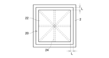
- FIG. 3 is a top view showing a state in which the presser plate is inserted into the sagger.
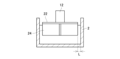
- FIG. 3 is a side view showing a state in which the presser plate is inserted into the sagger.
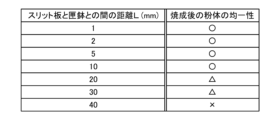
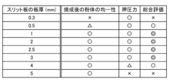
- a diagram showing the relationship between the distance between the slit plate and the side surface of the sagger and the uniformity of the powder after firing. The figure which shows the relationship between the thickness of a slit plate, the uniformity of powder after firing, and the relationship between the pressing force of a pressing device.
- FIG. 7 is a side view showing the tip of the slit plate of the powder filling device according to the second embodiment.
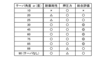
- FIG. 3 is a diagram showing the relationship between the taper angle ⁇ of the tip of the slit plate, the wear resistance of the slit plate, and the pressing force of the pressing device.
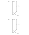
- FIG. 7 is a side view showing another example of the tip of the slit plate of the powder filling device according to the second embodiment.
- FIG. 7 is a side view showing the tip of the slit plate of the powder filling device according to the third embodiment.
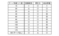
- FIG. 7 is a diagram showing the relationship between the taper angle ⁇ of the tip of the slit plate, the wear resistance of the slit plate, and the relationship between the pressing force of the pressing device.
- FIG. 7 is a side view showing another example of the tip of the slit plate of the powder filling device according to the third embodiment.
- the plurality of slit plates are arranged so that the powder filling device and the sagger are installed in the powder filling device when viewed from above. It may be arranged so as to match at least a diagonal line of the sagger. According to such a configuration, slit-like grooves can be formed up to the vicinity of the four corners of the sagger.
- each of the plurality of slit plates and the side wall of the sagger in a state where the sagger is installed in the powder filling device may be 30 mm or less. According to such a configuration, the entire powder contained in the sagger can be fired uniformly.
- the thickness of the slit plate may be 0.5 mm or more and 4 mm or less. According to such a configuration, the powder contained in the sagger can be fired uniformly while suppressing the pressing force of the pressing mechanism from increasing.
- the tip of the slit plate may be provided with a taper. According to such a configuration, the pressing force of the pressing mechanism can be reduced.
- the taper in a sixth aspect of the technology disclosed in this specification, in the fifth aspect described above, may be provided such that only one surface of the slit plate is inclined.
- the angle of the taper may be greater than or equal to 20 degrees and less than 90 degrees.
- the taper may be provided such that only one surface of the slit plate is inclined.
- the angle of the taper may be greater than or equal to 30 degrees and less than or equal to 85 degrees. According to such a configuration, the pressing force of the pressing mechanism can be further reduced while maintaining sufficient wear resistance of the tip of the slit plate.
- the taper in the fifth aspect described above, may be provided such that both surfaces of the slit plate are inclined.
- the angle of the taper may be greater than or equal to 20 degrees and less than 180 degrees.
- the taper may be provided such that both surfaces of the slit plate are inclined.
- the angle of the taper may be greater than or equal to 30 degrees and less than or equal to 170 degrees. According to such a configuration, the pressing force of the pressing mechanism can be further reduced while maintaining sufficient wear resistance of the tip of the slit plate.
- the slit plate is made of stainless steel, titanium, nickel, polyvinyl chloride, or tungsten carbide. It may be made of one or more materials. According to such a configuration, the slit plate is less likely to wear out when the slit plate is inserted into the powder. Therefore, it is possible to reduce the mixing of the abrasion powder of the slit plate, which is generated due to wear of the slit plate, into the powder. Furthermore, even if the abrasion powder of the slit plate should mix into the powder (that is, the powder before firing), there is an effect that it will not cause a major problem in terms of the quality of the powder after firing.
- the surface of the slit plate may be buffed. According to such a configuration, unevenness on the surface of the slit plate is reduced. Therefore, the pressing force of the pressing mechanism can be reduced, and the surface of the slit plate can be made less likely to wear out.
- the surface of the slit plate may be coated with Teflon (registered trademark).
- a powder filling device 10 is used to compact and fill powder into the sagger 2.
- the object to be processed stored in the sagger 2 is powder of a positive electrode material for a lithium ion battery (hereinafter also simply referred to as "powder").
- this embodiment uses a sagger 2 that is approximately rectangular (more specifically, approximately square) when viewed from above.
- the inner dimension of the side wall of the sagger 2 used in this example is 306 mm on one side.
- the powder filling device 10 of this embodiment has a substantially rectangular shape when viewed from above, and can be used to compress and fill powder into a sagger 2 whose side wall has an inner dimension of 80 to 380 mm. can.
- the powder filling device 10 includes a pressing plate 20 and a pressing device 12.
- the pressing plate 20 compacts the powder in the sagger 2. That is, a positioning projection (not shown) is provided on the mounting surface on which the sagger 2 is mounted, and the sagger 2 is positioned at a predetermined position on the mounting surface by this positioning projection.
- the pressing plate 20 is positioned at a preset position with respect to the mounting surface of the sagger 2. As a result, the pressing plate 20 can be inserted into a predetermined position inside the sagger 2 placed on the mounting surface, and the powder inside the sagger 2 can be compacted. .
- the pressing device 12 is arranged above the pressing plate 20 and is configured to move the pressing plate 20 forward and backward with respect to the sagger 2 (move it in the vertical direction). As the pressing plate 20 descends toward the inside of the sagger 2, the powder inside the sagger 2 is pressed.
- the pressing device 12 can be one that is used in a known powder filling device, so its detailed configuration will be omitted.
- the holding plate 20 includes a consolidation plate 22 and a plurality of slit plates 24.
- the consolidation plate 22 has a shape slightly smaller than the inner peripheral surface of the side wall of the sagger 2 when viewed from above. That is, in this embodiment, the consolidation plate 22 has a substantially rectangular shape and can be accommodated within the sagger 2.
- the consolidation plate 22 has a shape such that when the pressing plate 20 is housed in the sagger 2, the distance L from the side surface of the sagger 2 is within 30 mm.
- the pressing plate 20 is inserted toward the sagger 2 so that the center of the consolidation plate 22 substantially coincides with the center of the bottom surface of the sagger 2.
- the distance L between the consolidation plate 22 and the side surface of the sagger 2 is within 30 mm.
- the consolidation plate 22 is a flat plate, and its lower surface is parallel to the bottom surface of the sagger 2.
- a pressing device 12 is arranged on the upper surface of the consolidation plate 22. With the powder contained in the sagger 2, the compaction plate 22 is moved toward the sagger 2 by the pressing device 12, thereby consolidating the powder within the sagger 2. By compacting the powder in the sagger 2, the amount of powder packed can be increased, and a large amount of powder can be fired efficiently.
- a plurality of slit plates 24 are arranged on the lower surface of the consolidation plate 22.
- the slit plate 24 has a flat plate shape and is installed perpendicularly to the lower surface of the consolidation plate 22. That is, the slit plate 24 extends downward from the lower surface (i.e., pressing surface) of the consolidation plate 22.
- the dimensions of the plurality of slit plates 24 in the height direction are the same.
- the plurality of slit plates 24 are arranged radially when viewed from above. At least four of the plurality of slit plates 24 extend from the center of the consolidation plate 22 toward the corners when viewed from above.
- the slit plate 24 is arranged at a position that coincides with a diagonal line connecting the corners of the rectangular bottom surface of the sagger 2.
- eight slit plates 24 are arranged and extend from the center of the consolidation plate 22 toward the outer periphery of the consolidation plate 22. Of the eight slit plates 24, four slit plates 24 extend to the corners of the consolidation plate 22, and the remaining four slit plates 24 extend toward the center of the side of the consolidation plate 22. There is.
- the holding plate 20 is provided with a plurality of slit plates 24, when the holding plate 20 presses the powder in the sagger 2, a plurality of grooves are formed in the powder in the sagger 2. .
- the amount of powder packed into the sagger 2 can be increased, but it becomes difficult to take out the powder from the sagger 2 after firing.
- By forming a plurality of grooves in the powder when compacted it becomes easier to take out the powder from the sagger 2 after firing.
- the powder is compacted and filled into the sagger 2, it becomes difficult for the gas necessary for the firing reaction to be supplied to the inside of the powder.
- reaction gas generated from the powder during firing is difficult to be discharged to the outside of the sagger 2.
- the reaction gas generated from the powder located near the bottom of the sagger 2 is difficult to be discharged to the outside of the sagger 2.
- the reaction gas generated from the powder located near the bottom of the sagger 2 is easily discharged, and the entire powder inside the sagger 2 is uniformly distributed. Can be fired.
- each slit plate 24 extends from the center of the consolidation plate 22 to the side surface of the consolidation plate 22. Therefore, when the powder in the sagger 2 is pressed by the pressing plate 20, the distance L between the end of each slit plate 24 (that is, the end on the side surface of the consolidation plate 22) and the side surface of the sagger 2 is within 30mm. As a result, grooves are also formed in the powder located near the side surface of the sagger 2, and the gas required during the firing reaction of the sagger 2 is easily supplied to the inside of the powder. Furthermore, the reaction gas generated from the powder located near the side surface of the sagger 2 is also easily discharged. Therefore, it is possible to prevent the firing state from becoming uneven between the powder located near the center of the sagger 2 and the powder located near the side of the sagger 2.
- the slit plates 24 were composed of eight pieces, but the configuration is not limited to this.
- the slit plates may include those extending toward the corners of the consolidation plate 22, and may be composed of only four slit plates extending toward the corners of the consolidation plate 22, for example.
- the slit plates 24 may further include slit plates arranged between each of the eight slit plates 24 of this embodiment, or may be composed of 16 slit plates.
- the slit plate 24 is made of metal, and in this embodiment, it is made of stainless steel.
- the slit plate 24 may be made of metal or resin, and may be made of, for example, titanium, nickel, polyvinyl chloride (PVC), or tungsten carbide.
- PVC polyvinyl chloride
- the slit plate 24 becomes less likely to wear out, and the abrasion powder generated by the wear of the slit plate 24 when pressing the powder in the sagger 2 with the pressing plate 20 is reduced. Contamination with powder can be reduced. Further, the surface of the slit plate 24 is buffed. This reduces the unevenness on the surface of the slit plate 24, making the surface of the slit plate 24 less likely to wear out.
- the abrasion powder of the slit plate should mix into the powder (that is, the powder before firing), there is an effect that it will not cause a major problem in terms of the quality of the powder after firing.
- the pressing force of the pressing device 12 can be reduced.
- the surface of the slit plate 24 may be coated with a coating material capable of reducing unevenness on the surface of the slit plate 24, for example, may be coated with Teflon (registered trademark).
- each slit plate 24 is arranged so that when the holding plate 20 is housed in the sagger 2, the distance L between it and the side surface (inner wall) of the sagger 2 is within 30 mm. .
- FIG. 4 shows the relationship between the distance L between the slit plate 24 and the side surface of the sagger 2 and the uniformity of the powder after firing.
- the uniformity of the powder after firing was evaluated as follows. After firing, the powder located near the center of the sagger 2 and the powder located near the side of the sagger 2 were collected from multiple locations, and the amount of lithium contained in each of the collected powders was measured. If the difference in the amount of lithium contained between the collected powders is less than the threshold value, the powder after firing is considered uniform, and if the difference in the amount of lithium exceeds the threshold value, the powder after firing is considered uniform. The body was assumed to be uneven.
- the uniformity of the powder after firing is determined. It was confirmed.
- the distance L between the slit plate 24 and the side surface of the sagger 2 was 1 mm to 10 mm, the powder after firing was uniform. Further, when the distance L between the slit plate 24 and the side surface of the sagger 2 was 20 mm to 30 mm, the powder after firing was not completely uniform, but was generally uniform.
- the powder after firing was non-uniform.
- the reason why the powder became uneven after firing when the distance L between the slit plate 24 and the side surface of the sagger 2 was 40 mm was because the groove formed by the slit plate 24 was located near the side surface of the sagger 2. It is assumed that this is because gases such as oxygen required during firing were not supplied to the entire powder because it was not formed. Furthermore, it is presumed that this is because the reaction gas generated from the powder near the side surface of the sagger 2 becomes difficult to discharge.
- the powder in the sagger 2 can be fired uniformly.
- the lower limit of the distance L between the slit plate 24 and the side surface of the sagger 2 is a value that does not allow the slit plate 24 to interfere with the sagger 2 when the pressing plate 20 presses the powder in the sagger 2. For example, it may be 1 mm.
- the lower limit of the distance L between the slit plate 24 and the side surface of the sagger 2 is It may be between a value greater than 0 mm and less than 1 mm.
- the slit plate 24 is formed to have a thickness of 0.5 mm or more and 4 mm or less.
- the slit plate 24 is formed with a constant thickness.
- FIG. 5 shows the relationship between the thickness of the slit plate 24, the uniformity of the powder after firing, and the pressing force of the pressing device 12.
- the pressing force of the pressing device 12 indicates the pressing force necessary to insert the slit plate 24 into the powder contained in the sagger 2. If a high pressing force is required, it is marked as unsuitable ( ⁇ ) in the table of FIG.
- the thickness of the slit plate 24 is 0.3 mm, 0.5 mm, 1 mm, 2 mm, 2.5 mm, 3 mm, 4 mm, and 5 mm
- the uniformity of the powder after firing is The pressing force was confirmed.
- the thickness of the slit plate 24 was 0.3 mm
- the powder after firing was non-uniform.
- the thickness of the slit plate 24 was 0.5 mm
- the powder after firing was sometimes uniform and sometimes non-uniform.
- the thickness of the slit plate 24 was 1 mm to 5 mm, the powder after firing was uniform.
- the powder becomes non-uniform after firing because the thickness of the slit plate 24 is thin and the width of the groove formed in the powder is also thin. This is because the grooves disappeared or the width of the grooves became thinner during the time between filling the powder with the powder filling device 10 and firing it (while moving to the firing process) or during the firing process. Guessed. Further, it is presumed that the reason why the powder after firing was sometimes uneven when the thickness of the slit plate 24 was 0.5 mm was the same as the above. From the above, it has been confirmed that by setting the thickness of the slit plate 24 to 0.5 mm or more, more preferably 1 mm or more, the powder in the sagger 2 can be fired uniformly.
- the slit plate 24 when the thickness of the slit plate 24 was 0.3 mm to 3 mm, the slit plate 24 could be inserted into the powder with an appropriate pressing force without increasing the size of the pressing device 12. Furthermore, when the thickness of the slit plate 24 was 4 mm, the slit plate 24 could be inserted into the powder by increasing the size of the pressing device 12. Furthermore, when the thickness of the slit plate 24 is 5 mm, the pressing device 12 needs to be considerably enlarged in order to insert the slit plate 24 into the powder, and it is difficult to insert the slit plate 24 into the powder. Ta. From the above, it was confirmed that the slit plate 24 can be inserted into the powder in the sagger 2 by setting the thickness of the slit plate 24 to 0.5 mm to 4 mm, more preferably 0.5 mm to 3 mm. .
- the slit plate 24 was formed with a constant thickness, but the structure is not limited to this.
- the slit plate 124 may be provided with a taper 126 at the tip.
- the slit plate 124 is provided with a taper 126 having only one side inclined.
- a taper 126 with an angle ⁇ of 20 degrees or more and less than 90 degrees is provided at the tip of the slit plate 124.
- FIG. 7 shows the relationship between the angle ⁇ of the taper 126 of the slit plate 124 and the wear resistance of the slit plate 124, and the relationship with the pressing force of the pressing device 12.
- the angle ⁇ of the taper 126 is 10 degrees, 20 degrees, 25 degrees, 30 degrees, 45 degrees, 60 degrees, 75 degrees, 85 degrees, 88 degrees, and 90 degrees (that is, without the taper 126). In each case, the wear resistance and pressing force of the slit plate 124 were confirmed. When the angle ⁇ of the taper 126 was 10 degrees, the thin region at the tip of the slit plate 124 became large, and when the presser plate 20 was inserted into the sagger 2, the tip of the slit plate 124 was easily damaged.
- the angle ⁇ of the taper 126 is 20 degrees to 25 degrees, the tip of the slit plate 124 is hardly damaged when the presser plate 20 is inserted into the sagger 2, and has wear resistance. Ta. Further, when the angle ⁇ of the taper 126 is 30 degrees to 90 degrees, the tip of the slit plate 124 will not be damaged when the presser plate 20 is inserted into the sagger 2, and it will have sufficient wear resistance. was. From the above, by setting the angle ⁇ of the taper 126 at the tip of the slit plate 124 to 20 degrees or more, more preferably 30 degrees or more, sufficient wear resistance can be achieved when the presser plate 20 is inserted into the sagger 2. It was confirmed that it has.
- the slit plate 124 could be inserted into the powder with an appropriate pressing force. Also, when the angle ⁇ of the taper 126 was 88 degrees to 90 degrees, the slit plate 124 could be inserted into the powder with an appropriate pressing force, but compared to the case where the angle ⁇ of the taper 126 was 10 degrees to 85 degrees. This required a large pressing force.
- the angle ⁇ is 90 degrees, the configuration is the same as that of the slit plate 24 in which the taper of the first embodiment is not provided.
- the slit plate 124 could be inserted into the powder with a smaller pressing force than the slit plate 24 without a taper. From the above, it was confirmed that by setting the angle ⁇ of the taper 126 to 10 degrees to 85 degrees, the slit plate 124 could be inserted into the powder in the sagger 2 with a small pressing force.
- the tip of the slit plate 124 provided with the taper 126 was sharp, but the configuration is not limited to this.
- the slit plate 124a may be provided with a C-shaped taper 126a whose tip is flattened.
- the slit plate 124b may be provided with a taper 126b having a rounded shape with a curved tip.
- the presser plate is similar to the case where the slit plate 124 is provided with a taper 126 with a sharp tip.
- the pressing force when inserting the sagger 20 into the sagger 2 can be reduced.
- the slit plates 124a, 124b are provided with a taper 126a with a C-shaped tip or a taper 126b with an R-shaped tip, when the presser plate 20 is inserted into the sagger 2, the tips of the slit plates 124a, 124b is less likely to be damaged, and wear resistance can be improved compared to when the slit plate 124 is provided with a taper 126 having a sharp tip.
- the slit plate 124 was provided with a taper 126 having only one side inclined, but the configuration is not limited to this.
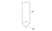
- the slit plate 224 may be provided with a taper 226 whose both surfaces are inclined.
- the tip of the slit plate 124 is provided with a taper 226 having an angle ⁇ of 20 degrees or more and less than 180 degrees.
- FIG. 10 shows the relationship between the angle ⁇ of the taper 226 of the slit plate 224 and the wear resistance of the slit plate 224, and the relationship with the pressing force of the pressing device 12.
- the wear resistance and pressing force of the slit plate 224 were confirmed.
- the angle ⁇ of the taper 226 was 10 degrees, the thin region at the tip of the slit plate 224 became large, and when the presser plate 20 was inserted into the sagger 2, the tip of the slit plate 224 was easily damaged. Further, when the angle ⁇ of the taper 226 is 20 degrees to 25 degrees, the tip of the slit plate 224 is hardly damaged when the presser plate 20 is inserted into the sagger 2, and has wear resistance. Ta.
- the tip of the slit plate 224 will not be damaged when the presser plate 20 is inserted into the sagger 2, and it will have sufficient wear resistance. was. From the above, even when the taper 226 whose both sides are inclined is provided at the tip of the slit plate 224, by setting the angle ⁇ of the taper 226 provided at the tip of the slit plate 224 to 20 degrees or more, more preferably 30 degrees or more, It was confirmed that the holding plate 20 had sufficient wear resistance when inserted into the sagger 2.
- the slit plate 224 could be inserted into the powder with an appropriate pressing force. Also, when the angle ⁇ of the taper 226 was 175 degrees to 180 degrees, the slit plate 224 could be inserted into the powder with an appropriate pressing force, but compared to the case where the angle ⁇ of the taper 226 was 10 degrees to 170 degrees. This required a large pressing force.
- the angle ⁇ is 180 degrees, the configuration is the same as that of the slit plate 24 in which the taper is not provided in the first embodiment.
- the slit plate 224 could be inserted into the powder with a smaller pressing force than the slit plate 24 without a taper. From the above, it was confirmed that by setting the angle ⁇ of the taper 226 to 10 degrees to 170 degrees, the slit plate 224 could be inserted into the powder in the sagger 2 with a small pressing force.
- the slit plate 226 was provided with a taper 226 whose both sides are inclined by the same angle, but the configuration is not limited to this.
- the slit plate 226 may be tapered at an angle ⁇ . Therefore, if the sum of the angle of inclination of one surface and the angle of inclination of the other surface is angle ⁇ , the slit plate is provided with a taper in which the angle of inclination of one surface and the angle of inclination of the other surface are different. You can leave it there.
- the tip of the slit plate 124 provided with the taper 226 does not need to be sharp.
- the slit plate 224a may be provided with a C-shaped taper 226a whose tip is flattened.
- the slit plate 224b may be provided with a taper 226b having a curved tip and a rounded shape.
Landscapes
- Engineering & Computer Science (AREA)
- Chemical & Material Sciences (AREA)
- Mechanical Engineering (AREA)
- Manufacturing & Machinery (AREA)
- Ceramic Engineering (AREA)
- Structural Engineering (AREA)
- Materials Engineering (AREA)
- Organic Chemistry (AREA)
- Inorganic Chemistry (AREA)
- Chemical Kinetics & Catalysis (AREA)
- Electrochemistry (AREA)
- General Chemical & Material Sciences (AREA)
- Furnace Charging Or Discharging (AREA)
- Battery Electrode And Active Subsutance (AREA)
- Filling Or Emptying Of Bunkers, Hoppers, And Tanks (AREA)
Abstract
Description
図面を参照して、本実施例に係る粉体充填装置10について説明する。粉体充填装置10は、匣鉢2内に粉体を圧密して充填するために用いられる。本実施例では、匣鉢2に収容される被処理物は、リチウムイオン電池の正極材の粉体(以下、単に「粉体」ともいう)である。また、図1及び図2に示すように、本実施例では、上面視したときに略矩形(詳細には、略正方形)となる匣鉢2を用いている。本実施例で用いる匣鉢2の側壁の内側寸法は、1辺が306mmである。なお、本実施例の粉体充填装置10は、上面視したきに略矩形であり、側壁の内側寸法が80~380mmの匣鉢2に、粉体を圧密して充填するために用いることができる。
上記の実施例1では、スリット板24は、一定の板厚で形成されていたが、このような構成に限定されない。例えば、図6に示すように、スリット板124は、先端にテーパ126が設けられていてもよい。本実施例では、スリット板124には、片面のみが傾斜するテーパ126が設けられている。スリット板124の先端にテーパ126を設けることによって、スリット板124を粉体に挿入し易くなり、押圧装置12の押圧力を低減することできる。
上記の実施例2では、スリット板124には、片面のみが傾斜するテーパ126が設けられていたが、このような構成に限定されない。例えば、図9に示すように、スリット板224には、両面が傾斜するテーパ226が設けられていてもよい。本実施例では、スリット板124の先端には、20度以上かつ180度未満の角度βのテーパ226が設けられる。図10は、スリット板224のテーパ226の角度βについて、スリット板224の耐摩耗性との関係、及び、押圧装置12の押圧力との関係を示している。
Claims (12)
- 匣鉢に粉体を圧密して充填する粉体充填装置であって、
前記匣鉢内の前記粉体を圧密する押さえ板と、
前記押さえ板を前記匣鉢内の前記粉体に向かって押圧する押圧機構と、を備えており、
前記押さえ板は、
前記粉体に当接して前記粉体を圧密する押さえ面を有する圧密板と、
前記圧密板の下面に設置され、前記押さえ面から下方に伸びる複数のスリット板と、を備えており、
前記複数のスリット板は、前記粉体充填装置に前記匣鉢を設置した状態で前記粉体充填装置及び前記匣鉢を上面視したときに、放射状に配置されており、
前記粉体充填装置に前記匣鉢を設置した状態における前記複数のスリット板のそれぞれと前記匣鉢の側壁との間の距離は、略同一である、粉体充填装置。 - 前記複数のスリット板は、前記粉体充填装置に前記匣鉢を設置した状態で前記粉体充填装置及び前記匣鉢を上面視したときに、少なくとも前記匣鉢の対角線と一致するように配置されている、請求項1に記載の粉体充填装置。
- 前記粉体充填装置に前記匣鉢を設置した状態における前記複数のスリット板のそれぞれと前記匣鉢の側壁との間の前記距離は、30mm以下である、請求項1に記載の粉体充填装置。
- 前記スリット板の板厚は、0.5mm以上かつ4mm以下である、請求項1に記載の粉体充填装置。
- 前記スリット板の先端には、テーパが設けられている、請求項1に記載の粉体充填装置。
- 前記テーパは、前記スリット板の片側の面のみが傾斜するように設けられており、
前記テーパの角度は、20度以上かつ90度未満である、請求項5に記載の粉体充填装置。 - 前記テーパは、前記スリット板の片側の面のみが傾斜するように設けられており、
前記テーパの角度は、30度以上かつ85度以下である、請求項5に記載の粉体充填装置。 - 前記テーパは、前記スリット板の両面が傾斜するように設けられており、
前記テーパの角度は、20度以上かつ180度未満である、請求項5に記載の粉体充填装置。 - 前記テーパは、前記スリット板の両面が傾斜するように設けられており、
前記テーパの角度は、30度以上かつ170度以下である、請求項5に記載の粉体充填装置。 - 前記スリット板は、ステンレス、チタン、ニッケル、ポリ塩化ビニル及びタングステンカーバイトのいずれか1種以上の材料で形成されている、請求項1に記載の粉体充填装置。
- 前記スリット板の表面は、バフ研磨処理されている、請求項1~10のいずれか一項に記載の粉体充填装置。
- 前記スリット板の表面は、テフロン(登録商標)コーティングされている、請求項1~10のいずれか一項に記載の粉体充填装置。
Priority Applications (3)
| Application Number | Priority Date | Filing Date | Title |
|---|---|---|---|
| JP2024519212A JP7773634B2 (ja) | 2022-05-02 | 2023-04-28 | 粉体充填装置 |
| CN202380024972.1A CN119212966A (zh) | 2022-05-02 | 2023-04-28 | 粉体填充装置 |
| US18/825,148 US12623427B2 (en) | 2022-05-02 | 2024-09-05 | Powder feeding device |
Applications Claiming Priority (2)
| Application Number | Priority Date | Filing Date | Title |
|---|---|---|---|
| JP2022-076143 | 2022-05-02 | ||
| JP2022076143 | 2022-05-02 |
Related Child Applications (1)
| Application Number | Title | Priority Date | Filing Date |
|---|---|---|---|
| US18/825,148 Continuation US12623427B2 (en) | 2022-05-02 | 2024-09-05 | Powder feeding device |
Publications (1)
| Publication Number | Publication Date |
|---|---|
| WO2023214548A1 true WO2023214548A1 (ja) | 2023-11-09 |
Family
ID=88646485
Family Applications (1)
| Application Number | Title | Priority Date | Filing Date |
|---|---|---|---|
| PCT/JP2023/016889 Ceased WO2023214548A1 (ja) | 2022-05-02 | 2023-04-28 | 粉体充填装置 |
Country Status (4)
| Country | Link |
|---|---|
| US (1) | US12623427B2 (ja) |
| JP (1) | JP7773634B2 (ja) |
| CN (1) | CN119212966A (ja) |
| WO (1) | WO2023214548A1 (ja) |
Citations (6)
| Publication number | Priority date | Publication date | Assignee | Title |
|---|---|---|---|---|
| JP2014172100A (ja) * | 2013-03-06 | 2014-09-22 | Nippon Steel & Sumikin Electronics Devices Inc | 押圧溝形成用スリット刃及びセラミックパッケージの製造方法 |
| JP2015218098A (ja) * | 2014-05-21 | 2015-12-07 | 住友金属鉱山株式会社 | リチウム遷移金属複合酸化物製造用匣鉢充填物およびリチウム遷移金属複合酸化物の製造方法 |
| JP2017206002A (ja) * | 2016-05-17 | 2017-11-24 | Jfeケミカル株式会社 | 焼成用容器への粉体充填方法及び粉体充填装置 |
| CN210036297U (zh) * | 2019-04-04 | 2020-02-07 | 合肥融捷能源材料有限公司 | 一种锂电池正极材料专用匣钵 |
| JP2020070232A (ja) * | 2018-10-26 | 2020-05-07 | 住友金属鉱山株式会社 | 匣鉢および匣鉢充填物、並びにリチウム金属複合酸化物の製造方法 |
| CN214490733U (zh) * | 2021-03-24 | 2021-10-26 | Ngk (苏州) 热工技术有限公司 | 切块装置 |
Family Cites Families (3)
| Publication number | Priority date | Publication date | Assignee | Title |
|---|---|---|---|---|
| TWI488827B (zh) * | 2010-03-01 | 2015-06-21 | Ngk Insulators Ltd | Cover |
| JP5460453B2 (ja) | 2010-05-06 | 2014-04-02 | 日本碍子株式会社 | 匣鉢内部への粉体充填方法 |
| CN114068918B (zh) * | 2020-08-06 | 2024-08-06 | 比亚迪股份有限公司 | 磷酸铁锂正极活性材料及其制备方法及电池 |
-
2023
- 2023-04-28 CN CN202380024972.1A patent/CN119212966A/zh active Pending
- 2023-04-28 WO PCT/JP2023/016889 patent/WO2023214548A1/ja not_active Ceased
- 2023-04-28 JP JP2024519212A patent/JP7773634B2/ja active Active
-
2024
- 2024-09-05 US US18/825,148 patent/US12623427B2/en active Active
Patent Citations (6)
| Publication number | Priority date | Publication date | Assignee | Title |
|---|---|---|---|---|
| JP2014172100A (ja) * | 2013-03-06 | 2014-09-22 | Nippon Steel & Sumikin Electronics Devices Inc | 押圧溝形成用スリット刃及びセラミックパッケージの製造方法 |
| JP2015218098A (ja) * | 2014-05-21 | 2015-12-07 | 住友金属鉱山株式会社 | リチウム遷移金属複合酸化物製造用匣鉢充填物およびリチウム遷移金属複合酸化物の製造方法 |
| JP2017206002A (ja) * | 2016-05-17 | 2017-11-24 | Jfeケミカル株式会社 | 焼成用容器への粉体充填方法及び粉体充填装置 |
| JP2020070232A (ja) * | 2018-10-26 | 2020-05-07 | 住友金属鉱山株式会社 | 匣鉢および匣鉢充填物、並びにリチウム金属複合酸化物の製造方法 |
| CN210036297U (zh) * | 2019-04-04 | 2020-02-07 | 合肥融捷能源材料有限公司 | 一种锂电池正极材料专用匣钵 |
| CN214490733U (zh) * | 2021-03-24 | 2021-10-26 | Ngk (苏州) 热工技术有限公司 | 切块装置 |
Also Published As
| Publication number | Publication date |
|---|---|
| US20240424757A1 (en) | 2024-12-26 |
| US12623427B2 (en) | 2026-05-12 |
| CN119212966A (zh) | 2024-12-27 |
| JP7773634B2 (ja) | 2025-11-19 |
| JPWO2023214548A1 (ja) | 2023-11-09 |
Similar Documents
| Publication | Publication Date | Title |
|---|---|---|
| KR101821411B1 (ko) | 갑발 내부에의 분체 충전 방법 | |
| CN102097629A (zh) | 成型件 | |
| JP2009505405A (ja) | 最小密度勾配を有する改善された溝付き陽極及びそれを備えたコンデンサ | |
| WO2006082760A1 (ja) | 焼結体、スパッタリングターゲット及び成形型並びにそれを用いた焼結体の製造方法 | |
| KR20120027407A (ko) | 분말 금속 플레이트의 제조 방법 | |
| JP3356728B2 (ja) | 燃料電池セパレータ用の粉末状原料の投入装置、燃料電池セパレータの製造方法、及び燃料電池セパレータ | |
| JP2004071456A (ja) | 多孔質導電板 | |
| EP1083034A2 (en) | A set of molding dies, molding structure, and molding process for fuel-cell separator | |
| JP2020070232A (ja) | 匣鉢および匣鉢充填物、並びにリチウム金属複合酸化物の製造方法 | |
| US6437278B1 (en) | Green compact electrode for discharge surface treatment | |
| JP7773634B2 (ja) | 粉体充填装置 | |
| JP4014982B2 (ja) | アーク蒸発源用のロッドターゲット、その製造方法及びアーク蒸着装置 | |
| EP0298557A1 (en) | Method of manufacturing a dispenser cathode | |
| US20250058377A1 (en) | Powder press and method of forming electrochemical cell stack interconnects by powder pressing | |
| JPH1017904A (ja) | 通電焼結方法 | |
| KR101047717B1 (ko) | 용융탄산염 연료전지용 전해질 함침형 다공성 금속 전극의 동시 건식 제조 방법 | |
| CN224182079U (zh) | 一种用于硬质合金大板材烧结的石墨舟皿装置及组装结构 | |
| JP2535394B2 (ja) | ナトリウム―硫黄電池用の固体電解質管及びその表面整形方法 | |
| KR101044163B1 (ko) | 건식 공정을 이용한 용융탄산염 연료전지용 다공성 금속 전극의 제조방법 | |
| US20170084397A1 (en) | Methods to Reduce Case Height for Capacitors | |
| JP2003300782A (ja) | 焼成用セッター及びその製造方法 | |
| US7718108B2 (en) | Method of manufacturing a fuel cell bipolar plate | |
| KR101554335B1 (ko) | 나트륨 유황 전지의 양극재 및 양극재 제조 방법 | |
| JP7341665B2 (ja) | 交互嵌合された指状部の共押出成形のための構造 | |
| JP2004306414A (ja) | セラミックス成形用金型 |
Legal Events
| Date | Code | Title | Description |
|---|---|---|---|
| 121 | Ep: the epo has been informed by wipo that ep was designated in this application |
Ref document number: 23799478 Country of ref document: EP Kind code of ref document: A1 |
|
| WWE | Wipo information: entry into national phase |
Ref document number: 2024519212 Country of ref document: JP |
|
| WWE | Wipo information: entry into national phase |
Ref document number: 202380024972.1 Country of ref document: CN |
|
| NENP | Non-entry into the national phase |
Ref country code: DE |
|
| WWP | Wipo information: published in national office |
Ref document number: 202380024972.1 Country of ref document: CN |
|
| 122 | Ep: pct application non-entry in european phase |
Ref document number: 23799478 Country of ref document: EP Kind code of ref document: A1 |