WO2023214460A1 - カメラ及びカメラの製造方法 - Google Patents
カメラ及びカメラの製造方法 Download PDFInfo
- Publication number
- WO2023214460A1 WO2023214460A1 PCT/JP2022/019555 JP2022019555W WO2023214460A1 WO 2023214460 A1 WO2023214460 A1 WO 2023214460A1 JP 2022019555 W JP2022019555 W JP 2022019555W WO 2023214460 A1 WO2023214460 A1 WO 2023214460A1
- Authority
- WO
- WIPO (PCT)
- Prior art keywords
- camera
- camera lens
- lens unit
- space
- adhesive
- Prior art date
- Legal status (The legal status is an assumption and is not a legal conclusion. Google has not performed a legal analysis and makes no representation as to the accuracy of the status listed.)
- Ceased
Links
Images




Classifications
-
- G—PHYSICS
- G02—OPTICS
- G02B—OPTICAL ELEMENTS, SYSTEMS OR APPARATUS
- G02B7/00—Mountings, adjusting means, or light-tight connections, for optical elements
- G02B7/02—Mountings, adjusting means, or light-tight connections, for optical elements for lenses
-
- G—PHYSICS
- G03—PHOTOGRAPHY; CINEMATOGRAPHY; ANALOGOUS TECHNIQUES USING WAVES OTHER THAN OPTICAL WAVES; ELECTROGRAPHY; HOLOGRAPHY
- G03B—APPARATUS OR ARRANGEMENTS FOR TAKING PHOTOGRAPHS OR FOR PROJECTING OR VIEWING THEM; APPARATUS OR ARRANGEMENTS EMPLOYING ANALOGOUS TECHNIQUES USING WAVES OTHER THAN OPTICAL WAVES; ACCESSORIES THEREFOR
- G03B15/00—Special procedures for taking photographs; Apparatus therefor
-
- G—PHYSICS
- G03—PHOTOGRAPHY; CINEMATOGRAPHY; ANALOGOUS TECHNIQUES USING WAVES OTHER THAN OPTICAL WAVES; ELECTROGRAPHY; HOLOGRAPHY
- G03B—APPARATUS OR ARRANGEMENTS FOR TAKING PHOTOGRAPHS OR FOR PROJECTING OR VIEWING THEM; APPARATUS OR ARRANGEMENTS EMPLOYING ANALOGOUS TECHNIQUES USING WAVES OTHER THAN OPTICAL WAVES; ACCESSORIES THEREFOR
- G03B30/00—Camera modules comprising integrated lens units and imaging units, specially adapted for being embedded in other devices, e.g. mobile phones or vehicles
Definitions
- the present disclosure relates to a camera and a method of manufacturing the camera.
- Patent Document 1 One of the purposes of the vehicle-mounted camera described in Patent Document 1, which is common to the camera according to the present disclosure in that it is for vehicle use, is to prevent foreign matter such as water droplets and dust from entering the camera case main body.
- an O-ring seals between a space inside the camera case body and a space outside the camera case body.
- An object of the present disclosure is to make it easier to insert a camera lens unit into a camera housing than before, and to fix the camera lens unit to the camera housing more stably than before, and It is an object of the present invention to provide a camera and a method for manufacturing the camera that can simultaneously ensure airtightness between a camera lens unit and a camera housing.
- a camera includes a camera lens for imaging a subject, a camera lens unit in which the camera lens is fixed, and an image sensor that receives light collected by the camera lens. , a space for holding the image sensor, an opening for inserting the camera lens unit toward the space, and an air provided between the camera lens unit and for passing the air in the space to the outside.
- the present invention includes a camera casing having a hole, the space of which is sealed by applying adhesive to the air hole, and a camera lens unit is fixed to the camera casing.
- the camera according to the present disclosure it is possible to make it easier to insert the camera lens unit into the camera housing than before, and to fix the camera lens unit to the camera housing more stably than before. It is also possible to simultaneously ensure airtightness between the camera lens unit and the camera housing.
- FIG. 2 is a cross-sectional view taken along chain line A1-A2 in FIG. 1, showing the configuration of camera C according to the embodiment.
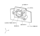
- It is a perspective view showing the composition of camera housing KY of an embodiment.
- It is a top view showing the composition of camera housing KY of an embodiment.
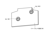
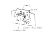
- It is a bottom view showing the composition of camera housing KY of an embodiment. It shows before applying the adhesive SE of the embodiment. It shows after applying the adhesive SE of the embodiment.
- the camera C of the embodiment is configured to monitor, for example, a position in front of the driver or on the dashboard of the vehicle. It is located between the driver's seat and passenger seat.
- FIG. 1 is a top view showing the configuration of a camera C according to an embodiment.
- FIG. 2 is a sectional view taken along the chain line A1-A2 in FIG. 1, showing the configuration of the camera C of the embodiment.
- the camera C of the embodiment mainly includes a camera lens unit CLU, a camera housing KY, an image sensor IS, an image sensor board ISK, an adhesive SE, and a screw. Includes NE1 and NE2.
- the camera lens CL corresponds to a "camera lens”
- the camera lens unit CLU corresponds to a “camera lens unit”
- the image sensor IS corresponds to an "image sensor”
- the camera housing KY corresponds to a “camera housing.” corresponds to "body”.
- the camera lens unit CLU has a conventionally known camera lens CL (not shown) fixed therein for capturing an image of a subject.
- the camera housing KY holds a camera lens unit CLU, as shown in FIG.
- FIG. 3 is a perspective view showing the configuration of the camera housing KY of the embodiment.
- FIG. 4 is a top view showing the configuration of the camera housing KY of the embodiment.
- FIG. 5 is a bottom view showing the configuration of the camera housing KY of the embodiment.
- the camera housing KY has an opening KA for inserting a camera lens unit CLU (for example, shown in FIG. 2).
- the opening KA corresponds to an "opening".
- the camera housing KY also has an air hole portion KU, as shown in FIGS. 3 and 4. As shown in FIG. 2, the air hole portion KU is provided between the camera lens unit and parallel to the direction of the optical axis KJ of the camera lens unit CLU, that is, along the Y axis. .
- the air hole portion KU holds the space KK (shown in FIG. 2) around the image sensor IS in the camera housing KY, that is, the image sensor IS.
- the air in the space KK for this purpose is passed to the outside.
- the space KK corresponds to a "space”
- the air hole portion KU corresponds to an "air hole”.
- the camera housing KY also has a slit portion SL, as shown in FIG. 3.
- the slit portion SL is defined in a part of the threaded portion (camera housing) NE (KY) of the camera housing KY.
- the slit part SL is a space for applying adhesive SE (for example, shown in FIG. 2).
- a side surface (slit portion) SO1 (SL) and a side surface (slit portion) SO2 (SL) are provided on both sides of the TE (SL).
- the slit portion SL corresponds to a "slit”.
- the camera housing KY also has a threaded portion (camera housing) NE(KY), as shown in FIG.
- the threaded portion (camera housing) NE (KY) is provided on the inner surface that defines the opening KA of the camera housing KY.
- the threaded part (camera housing) NE (KY) cooperates with the threaded part (camera lens unit) NE (CLU) of the camera lens unit CLU (for example, shown in FIG. 2), and for example, connects the threaded part (camera housing) to the camera housing KY. It functions to insert the camera lens unit CLU, adjust the focus position of the camera lens unit CLU, and hold the camera lens unit CLU by the camera housing KY.
- the image sensor board ISK is further attached to the camera housing KY with screws NE1 and NE2 (shown in FIG. 5).
- the image sensor IS is mounted on the image sensor board ISK, as shown in FIG. 2, to receive the light collected by the camera lens CL.
- Adhesives SE are, for example, UV-curing adhesives, moisture-curing adhesives, heat-curing adhesives, and hybrid adhesives that cure with both UV and heat.
- the screws NE1 and NE2 fix the image sensor board ISK to the camera housing KY, as shown in FIG. 2.
- the optical axis KJ is inserted into the opening KA of the camera housing KY (for example, shown in FIG. (Illustrated in FIG. 2), that is, the camera lens unit CLU is inserted along the Y axis from a position far from the image sensor IS to a position close to the image sensor IS.
- the air existing in the space KK (shown in FIG. 2) around the image sensor IS is discharged to the outside through the air hole KU. , are not compressed within the space KK. This makes it easier to insert the camera lens unit CLU than in the conventional case where the air described above is compressed within the space KK.
- the focus position of the camera lens unit CLU with respect to the image sensor light receiving portion ISJ of the image sensor IS is adjusted in the direction of the optical axis KJ.
- the threaded part (camera lens unit) NE (CLU) and the threaded part (camera housing) NE (KY) fit together.
- the camera lens unit CLU is rotated about the optical axis KJ, and more specifically, the position of the camera lens unit CLU in the direction of the optical axis KJ is changed, thereby adjusting the focus position of the camera lens unit CLU.
- FIG. 6 shows the adhesive SE of the embodiment before being applied.
- FIG. 7 shows the adhesive SE of the embodiment after being applied.
- adhesive is applied to the slit portion SL of the camera housing KY including the air hole portion KU (for example, shown in FIG. 3), as shown in FIG. Apply SE. More specifically, the adhesive SE was applied to the side surface (slit portion) SO1 (SL), the side surface (slit portion) SO2 (SL), and the bottom surface (slit portion) TE (SL) of the slit portion SL of the camera housing KY. (also shown in FIG. 4) and the threaded portion (camera lens unit) NE (CLU) (shown in FIG. 6). After the above-described application, the adhesive SE is cured, for example, by UV irradiation. Thereby, the adhesive SE fixes the camera lens unit CLU to the camera housing KY and seals the space KK (shown in FIG. 2).
- the adhesive SE is also applied to the side surface (slit portion) SO1 (SL), the side surface (slit portion) SO2 (SL), and the bottom surface in the slit portion SL of the camera housing KY. Apply in a manner that it touches the (slit part) TE (SL) and the screw part (camera lens unit) NE (CLU).
- the slit portion SL has a structure that allows the adhesive SE to be applied in the manner described above.
- the shape of the adhesive SE is not easily deformed from the time when the adhesive SE is applied until the time when it is cured. In other words, the shape when the adhesive SE is applied is easily maintained.
- the surface area where the adhesive SE comes into contact with the camera housing KY can be expanded as much as possible.
- the camera C of the embodiment it is possible to ensure stable fixation between the camera lens unit CLU and the camera housing KY as described above, and at the same time, ensure the above-described airtightness. More specifically, by closing the air hole KU of the camera housing KY with the adhesive SE, the space KK around the image sensor IS is sealed. By sealing the space KK, it is possible to suppress foreign matter from entering the space KK from the outside after the assembly of the camera C is completed, and it is possible to substantially prevent the foreign matter from entering.
- the sensing function of the driver monitoring system in which the camera C is mounted can prevent the foreign matter from adhering to the image sensor IS. It is possible to avoid a situation where the temperature decreases due to
- the camera according to the present disclosure can be used, for example, to insert a camera lens unit into a camera housing.
- C camera, CL camera lens, CLU camera lens unit IS image sensor, ISJ image sensor light receiving section, ISK image sensor board, KA opening, KJ optical axis, KK space, KU air hole, KY camera housing, NE1 screw , NE2 screw, SE adhesive, SL slit part.
Landscapes
- Physics & Mathematics (AREA)
- General Physics & Mathematics (AREA)
- Optics & Photonics (AREA)
- Studio Devices (AREA)
Abstract
カメラ(C)は、被写体を撮像するためのカメラレンズと、前記カメラレンズが内部に固定されたカメラレンズユニット(CLU)と、前記カメラレンズにより集光された光を受けるイメージセンサ(IS)と、前記イメージセンサ(IS)を保持するための空間(KK)と、前記空間(KK)に向けて前記カメラレンズユニット(CLU)を挿入するための開口部(KA)と、前記カメラレンズユニット(CLU)との間に設けられた、前記空間(KK)内の空気を外部へ通すための空気穴(KU)と、を有するカメラ筐体(KY)であって、前記空気穴(KU)への接着剤(SE)の塗布により、前記空間(KK)が密閉され、かつ、前記カメラレンズユニット(CLU)が前記カメラ筐体(KY)に固着される前記カメラ筐体(KY)と、を含む。
Description
本開示は、カメラ及びカメラの製造方法に関する。
本開示に係るカメラと車載用である点で共通する特許文献1に記載の車載カメラは、カメラケース本体部内に水滴や埃等の異物が侵入するのを防ぐことを目的の一つとする。前記車載カメラは、前記目的を達成すべく、Oリングが、前記カメラケース本体部内の空間とその外部の空間との間をシールする。
しかしながら、上記した車載カメラでは、前記カメラケース本体部にレンズを装着するときに、前記カメラケース本体部内の空気を逃すことができないことから、前記レンズの装着を容易に行うことができなかった。上記した車載カメラでは、また、前記レンズを装着する方向と垂直な面における一方向での一点で前記レンズを固定することから、前記レンズの姿勢が傾くおそれがあった。
本開示の目的は、カメラレンズユニットをカメラ筐体に挿入することを従来に比して容易にし、かつ、カメラレンズユニットをカメラ筐体に従来に比して安定的に固定すること、及び、カメラレンズユニットとカメラ筐体との間に密閉性を確保することを同時に行うことが可能なカメラ及びカメラの製造方法を提供することにある。
上記した課題を解決すべく、本開示に係るカメラは、被写体を撮像するためのカメラレンズと、カメラレンズが内部に固定されたカメラレンズユニットと、カメラレンズにより集光された光を受けるイメージセンサと、イメージセンサを保持するための空間と、空間に向けてカメラレンズユニットを挿入するための開口部と、カメラレンズユニットとの間に設けられた、空間内の空気を外部へ通すための空気穴と、を有するカメラ筐体であって、空気穴への接着剤の塗布により、空間が密閉され、かつ、カメラレンズユニットがカメラ筐体に固着されるカメラ筐体と、を含む。
本開示に係るカメラによれば、カメラレンズユニットをカメラ筐体に挿入することを従来に比して容易にし、かつ、カメラレンズユニットをカメラ筐体に従来に比して安定的に固定すること、及び、カメラレンズユニットとカメラ筐体との間に密閉性を確保することを同時に行うことが可能となる。
本開示に係るカメラ及びカメラの製造方法の実施形態について説明する。
実施形態.
〈実施形態〉
実施形態のカメラCについて説明する。
〈実施形態〉
実施形態のカメラCについて説明する。
実施形態のカメラCは、自動車等の車両の運転者の状態(例えば、運転者の脇見、居眠り、姿勢くずれ)を監視すべく、例えば、前記運転者の前方の位置、前記車両のダッシュボード上における、運転席及び助手席間の位置に配置される。
〈実施形態の構成〉
〈カメラC〉
図1は、実施形態のカメラCの構成を示す上面図である。
〈カメラC〉
図1は、実施形態のカメラCの構成を示す上面図である。
図2は、実施形態のカメラCの構成を示す、図1の鎖線A1-A2での断面図である。
実施形態のカメラCは、図1、図2に示されるように、主に、カメラレンズユニットCLUと、カメラ筐体KYと、イメージセンサISと、イメージセンサ基板ISKと、接着剤SEと、ねじNE1、NE2と、を含む。
〈カメラレンズCL〉
カメラレンズCLは、「カメラレンズ」に対応し、カメラレンズユニットCLUは、「カメラレンズユニット」に対応し、イメージセンサISは、「イメージセンサ」に対応し、カメラ筐体KYは、「カメラ筐体」に対応する。
カメラレンズCLは、「カメラレンズ」に対応し、カメラレンズユニットCLUは、「カメラレンズユニット」に対応し、イメージセンサISは、「イメージセンサ」に対応し、カメラ筐体KYは、「カメラ筐体」に対応する。
カメラレンズユニットCLUは、その内部に従来知られた、被写体を撮像するためのカメラレンズCL(図示せず。)が固定されている。
〈カメラ筐体KY〉
カメラ筐体KYは、図2に示されるように、カメラレンズユニットCLUを保持する。
カメラ筐体KYは、図2に示されるように、カメラレンズユニットCLUを保持する。
図3は、実施形態のカメラ筐体KYの構成を示す斜視図である。
図4は、実施形態のカメラ筐体KYの構成を示す上面図である。
図5は、実施形態のカメラ筐体KYの構成を示す底面図である。
カメラ筐体KYは、図3に示されるように、カメラレンズユニットCLU(例えば、図2に図示。)を挿入するための開口部KAを有する。
開口部KAは、「開口部」に対応する。
カメラ筐体KYは、また、図3、図4に示されるように、空気穴部KUを有する。空気穴部KUは、図2に示されるように、前記カメラレンズユニットとの間に、かつ、カメラレンズユニットCLUの光軸KJの方向と平行に、即ち、Y軸に沿って設けられている。空気穴部KUは、カメラ筐体KYにカメラレンズユニットCLUを挿入するときに、カメラ筐体KY内におけるイメージセンサISの周辺の空間KK(図2に図示。)、即ち、イメージセンサISを保持するための空間KK内の空気を外部へ通す。
空間KKは、「空間」に対応し、空気穴部KUは、「空気穴」に対応する。
カメラ筐体KYは、また、図3に示されるように、スリット部SLを有する。スリット部SLは、カメラ筐体KYのねじ部(カメラ筐体)NE(KY)の一部に規定されている。スリット部SLは、接着剤SE(例えば、図2に図示。)を塗布するための空間であり、接着剤SEの液だれを規制すべく、図4に示されるように、底面(スリット部)TE(SL)の両側に、側面(スリット部)SO1(SL)、及び側面(スリット部)SO2(SL)を備える。
スリット部SLは、「スリット」に対応する。
カメラ筐体KYは、また、図3に示されるように、ねじ部(カメラ筐体)NE(KY)を有する。ねじ部(カメラ筐体)NE(KY)は、カメラ筐体KYの開口部KAを規定する内側の面に設けられている。ねじ部(カメラ筐体)NE(KY)は、カメラレンズユニットCLUのねじ部(カメラレンズユニット)NE(CLU)(例えば、図2に図示。)と協働し、例えば、カメラ筐体KYへのカメラレンズユニットCLUの挿入、カメラレンズユニットCLUのフォーカス位置の調整、及びカメラ筐体KYによるカメラレンズユニットCLUの保持のために機能する。
カメラ筐体KYには、更に、図3に示されるように、イメージセンサ基板ISKが、ねじNE1、NE2(図5に図示。)により取り付けられている。
〈カメラC(続き)〉
図1、図2に戻り、説明を続ける。
図1、図2に戻り、説明を続ける。
イメージセンサISは、カメラレンズCLにより集光される光を受けるべく、図2に示されるように、イメージセンサ基板ISKに実装されている。
接着剤SEは、図2に示されるように、カメラレンズユニットCLUとカメラ筐体KYとを接着している。接着剤SEは、例えば、UV硬化接着剤、湿気硬化接着剤、熱硬化接着剤、並びに、UV及び熱の両者で硬化するハイブリッド接着剤である。
ねじNE1、NE2は、図3、図5を参照して上述したように、図2に示されるように、イメージセンサ基板ISKをカメラ筐体KYに固定している。
〈カメラCの製造方法〉
実施形態のカメラCの製造方法について説明する。
実施形態のカメラCの製造方法について説明する。
〈カメラレンズユニットCLUの挿入〉
カメラCを製造しようとするとき、まず、図1に示されるように、イメージセンサ基板ISKが取り付けられているカメラ筐体KYの開口部KA(例えば、図3に図示。)に、光軸KJ(図2に図示。)、即ち、Y軸に沿って、イメージセンサISから遠い位置からイメージセンサISに近い位置へ向けて、カメラレンズユニットCLUを挿入する。
カメラCを製造しようとするとき、まず、図1に示されるように、イメージセンサ基板ISKが取り付けられているカメラ筐体KYの開口部KA(例えば、図3に図示。)に、光軸KJ(図2に図示。)、即ち、Y軸に沿って、イメージセンサISから遠い位置からイメージセンサISに近い位置へ向けて、カメラレンズユニットCLUを挿入する。
カメラレンズユニットCLUをカメラ筐体KYへ挿入しているとき、イメージセンサISの周辺の空間KK(図2に図示。)に存在する空気は、空気穴部KUを介して外部へ排出され、即ち、空間KK内で圧縮されることはない。これにより、カメラレンズユニットCLUを挿入することが、上記した空気が空間KK内で圧縮されるような従来に比して容易になる。
〈カメラレンズユニットCLUの調整〉
上記した挿入の後に、イメージセンサISのイメージセンサ受光部ISJに対するカメラレンズユニットCLUのフォーカス位置を、光軸KJの方向について調整する。前記した調整のときに、ねじ部(カメラレンズユニット)NE(CLU)とねじ部(カメラ筐体)NE(KY)(いずれも図2に図示。)とが勘合する。これにより、カメラレンズユニットCLUを光軸KJについて回転させ、より詳しくは、光軸KJの方向における、カメラレンズユニットCLUの位置を変更し、これにより、カメラレンズユニットCLUのフォーカス位置を調整する。
上記した挿入の後に、イメージセンサISのイメージセンサ受光部ISJに対するカメラレンズユニットCLUのフォーカス位置を、光軸KJの方向について調整する。前記した調整のときに、ねじ部(カメラレンズユニット)NE(CLU)とねじ部(カメラ筐体)NE(KY)(いずれも図2に図示。)とが勘合する。これにより、カメラレンズユニットCLUを光軸KJについて回転させ、より詳しくは、光軸KJの方向における、カメラレンズユニットCLUの位置を変更し、これにより、カメラレンズユニットCLUのフォーカス位置を調整する。
〈カメラレンズユニットCLUの固着〉
図6は、実施形態の接着剤SEを塗布する前を示す。
図6は、実施形態の接着剤SEを塗布する前を示す。
図7は、実施形態の接着剤SEを塗布した後を示す。
上記した調整の後に、図6に示されるように、カメラ筐体KYにおける、空気穴部KU(例えば、図3に図示。)を含むスリット部SLに、図7に示されるように、接着剤SEを塗布する。より詳しくは、接着剤SEを、カメラ筐体KYのスリット部SLにおける、側面(スリット部)SO1(SL)、側面(スリット部)SO2(SL)、底面(スリット部)TE(SL)(いずれも図4に図示。)、及びねじ部(カメラレンズユニット)NE(CLU)(図6に図示。)に接する態様で塗布する。前記した塗布した後に、接着剤SEを、例えば、UV照射することにより硬化させる。これにより、接着剤SEは、カメラレンズユニットCLUをカメラ筐体KYに固着させ、かつ、空間KK(図2に図示。)を密閉する。
〈実施形態の効果〉
上述したように、実施形態のカメラCでは、カメラレンズユニットCLUをカメラ筐体KYへ挿入するときに、空間KK内の空気が空気穴部KUを通じて外部へ排出される。これにより、空間KK内の空気が外部へ排出されることなく圧縮される従来に比して、カメラレンズユニットCLUをカメラ筐体KYに挿入することをより容易に行うことができる。
上述したように、実施形態のカメラCでは、カメラレンズユニットCLUをカメラ筐体KYへ挿入するときに、空間KK内の空気が空気穴部KUを通じて外部へ排出される。これにより、空間KK内の空気が外部へ排出されることなく圧縮される従来に比して、カメラレンズユニットCLUをカメラ筐体KYに挿入することをより容易に行うことができる。
上述したように、実施形態のカメラCでは、また、接着剤SEを、カメラ筐体KYのスリット部SLにおける、側面(スリット部)SO1(SL)、側面(スリット部)SO2(SL)、底面(スリット部)TE(SL)、及びねじ部(カメラレンズユニット)NE(CLU)に接する態様で塗布する。換言すれば、スリット部SLが、接着剤SEを上記した態様で塗布することができる構造を有する。これにより、接着剤SEを塗布したときから硬化するときまでの間、接着剤SEの形状が変形され難く、換言すれば、接着剤SEを塗布したときの形状が、維持され易い。その結果、接着剤SEがカメラ筐体KYと接する表面積をできるだけ拡げることができ、換言すれば、少量の接着剤SEであっても、カメラレンズユニットCLUとカメラ筐体KYとの固定を、上記した態様を有さない従来に比して、より強固に、即ち、より安定にすることができる。
上述したように、実施形態のカメラCでは、上記したような、カメラレンズユニットCLU及びカメラ筐体KY間の安定的な固定と同時に、上記した密閉を確保することができる。より詳しくは、カメラ筐体KYの空気穴部KUが接着剤SEにより塞がれることにより、イメージセンサISの周辺の空間KKが密閉される。空間KKの密閉により、カメラCの組み立てが完了した後に、外部から空間KKへ異物が侵入することを抑制することができ、実質的に、前記異物が侵入することを阻止することができる。これにより、イメージセンサISに前記異物が付着することを抑制することができ、その結果、例えば、カメラCが搭載されているドライバモニタリングシステムのセンシング機能が、イメージセンサISへの前記異物の付着に起因して低下するとの事態を回避することができる。
なお、実施の形態の任意の構成要素の変形もしくは実施の形態の任意の構成要素の省略が可能である。
本開示に係るカメラは、例えば、カメラレンズユニットをカメラ筐体に挿入することに利用可能である。
C カメラ、CL カメラレンズ、CLU カメラレンズユニット、IS イメージセンサ、ISJ イメージセンサ受光部、ISK イメージセンサ基板、KA 開口部、KJ 光軸、KK 空間、KU 空気穴部、KY カメラ筐体、NE1 ねじ、NE2 ねじ、SE 接着剤、SL スリット部。
Claims (8)
- 被写体を撮像するためのカメラレンズと、
前記カメラレンズが内部に固定されたカメラレンズユニットと、
前記カメラレンズにより集光された光を受けるイメージセンサと、
前記イメージセンサを保持するための空間と、前記空間に向けて前記カメラレンズユニットを挿入するための開口部と、前記カメラレンズユニットとの間に設けられた、前記空間内の空気を外部へ通すための空気穴と、を有するカメラ筐体であって、前記空気穴への接着剤の塗布により、前記空間が密閉され、かつ、前記カメラレンズユニットが前記カメラ筐体に固着される前記カメラ筐体と、
を含むカメラ。 - 前記空気穴は、前記カメラ筐体内における前記イメージセンサの周辺の空間内の空気を外部へ通す請求項1に記載のカメラ。
- 前記空気穴は、前記カメラレンズユニットの光軸方向に平行に設けられている請求項1に記載のカメラ。
- 前記カメラ筐体は、前記接着剤を塗布するためのスリットであって前記接着剤の液だれを規制する前記スリットが設けられた、
請求項1に記載のカメラ。 - 被写体を撮像するためのカメラレンズが内部に固定されたカメラレンズユニットを、イメージセンサを保持するための空間と、前記空間に向けて前記カメラレンズユニットを挿入するための開口部と、前記カメラレンズユニットとの間に設けられた、前記空間内の空気を外部へ通すための空気穴と、を有するカメラ筐体の前記空気穴から前記空間内の空気を外部へ通しつつ、前記開口部を通じて前記空間に向けて挿入する第1の工程と、
前記第1の工程に引き続き、前記空気穴へ接着剤を塗布することにより、前記空間を密閉し、かつ、前記カメラレンズユニットを前記カメラ筐体に固着する第2の工程と、
を含むカメラの製造方法。 - 前記第2の工程は、前記空気穴から、前記カメラ筐体内における前記イメージセンサの周辺の空間内の空気を外部へ通す、
請求項5に記載のカメラの製造方法。 - 前記第1の工程は、前記空間内の空間を外部へ通すことを、前記カメラレンズユニットの光軸方向に平行に設けられている前記空気穴から行う、
請求項5に記載のカメラの製造方法。 - 前記第2の工程は、前記空気穴へ前記接着剤を塗布することを、前記カメラ筐体に設けられた、前記接着剤を塗布するためのスリットであって前記接着剤の液だれを規制する前記スリットで行う、
請求項5に記載のカメラの製造方法。
Priority Applications (2)
| Application Number | Priority Date | Filing Date | Title |
|---|---|---|---|
| PCT/JP2022/019555 WO2023214460A1 (ja) | 2022-05-06 | 2022-05-06 | カメラ及びカメラの製造方法 |
| JP2024519160A JP7802159B2 (ja) | 2022-05-06 | 2022-05-06 | カメラ及びカメラの製造方法 |
Applications Claiming Priority (1)
| Application Number | Priority Date | Filing Date | Title |
|---|---|---|---|
| PCT/JP2022/019555 WO2023214460A1 (ja) | 2022-05-06 | 2022-05-06 | カメラ及びカメラの製造方法 |
Publications (1)
| Publication Number | Publication Date |
|---|---|
| WO2023214460A1 true WO2023214460A1 (ja) | 2023-11-09 |
Family
ID=88646403
Family Applications (1)
| Application Number | Title | Priority Date | Filing Date |
|---|---|---|---|
| PCT/JP2022/019555 Ceased WO2023214460A1 (ja) | 2022-05-06 | 2022-05-06 | カメラ及びカメラの製造方法 |
Country Status (2)
| Country | Link |
|---|---|
| JP (1) | JP7802159B2 (ja) |
| WO (1) | WO2023214460A1 (ja) |
Cited By (1)
| Publication number | Priority date | Publication date | Assignee | Title |
|---|---|---|---|---|
| WO2026033610A1 (ja) * | 2024-08-06 | 2026-02-12 | 三菱電機モビリティ株式会社 | カメラモジュール、および、カメラモジュールの組み立て方法 |
Citations (5)
| Publication number | Priority date | Publication date | Assignee | Title |
|---|---|---|---|---|
| JP2009244787A (ja) * | 2008-03-31 | 2009-10-22 | Fujinon Corp | レンズ組立体、接着方法、および撮像装置 |
| WO2012008268A1 (ja) * | 2010-07-14 | 2012-01-19 | コニカミノルタオプト株式会社 | 撮像装置及びその製造方法 |
| CN204180154U (zh) * | 2014-04-02 | 2015-02-25 | 光宝电子(广州)有限公司 | 摄像头模组 |
| WO2016121165A1 (ja) * | 2015-01-30 | 2016-08-04 | 日本電産コパル株式会社 | 撮像装置、これを備える光学機器及び電子機器並びに撮像装置の製造方法 |
| JP2020016704A (ja) * | 2018-07-23 | 2020-01-30 | オリンパス株式会社 | 撮像ユニットの製造方法及び鏡枠構造 |
Family Cites Families (1)
| Publication number | Priority date | Publication date | Assignee | Title |
|---|---|---|---|---|
| JP6739368B2 (ja) * | 2017-01-30 | 2020-08-12 | アイホン株式会社 | カメラ付きインターホン機器におけるカメラのフォーカスの調整方法 |
-
2022
- 2022-05-06 WO PCT/JP2022/019555 patent/WO2023214460A1/ja not_active Ceased
- 2022-05-06 JP JP2024519160A patent/JP7802159B2/ja active Active
Patent Citations (5)
| Publication number | Priority date | Publication date | Assignee | Title |
|---|---|---|---|---|
| JP2009244787A (ja) * | 2008-03-31 | 2009-10-22 | Fujinon Corp | レンズ組立体、接着方法、および撮像装置 |
| WO2012008268A1 (ja) * | 2010-07-14 | 2012-01-19 | コニカミノルタオプト株式会社 | 撮像装置及びその製造方法 |
| CN204180154U (zh) * | 2014-04-02 | 2015-02-25 | 光宝电子(广州)有限公司 | 摄像头模组 |
| WO2016121165A1 (ja) * | 2015-01-30 | 2016-08-04 | 日本電産コパル株式会社 | 撮像装置、これを備える光学機器及び電子機器並びに撮像装置の製造方法 |
| JP2020016704A (ja) * | 2018-07-23 | 2020-01-30 | オリンパス株式会社 | 撮像ユニットの製造方法及び鏡枠構造 |
Cited By (1)
| Publication number | Priority date | Publication date | Assignee | Title |
|---|---|---|---|---|
| WO2026033610A1 (ja) * | 2024-08-06 | 2026-02-12 | 三菱電機モビリティ株式会社 | カメラモジュール、および、カメラモジュールの組み立て方法 |
Also Published As
| Publication number | Publication date |
|---|---|
| JPWO2023214460A1 (ja) | 2023-11-09 |
| JP7802159B2 (ja) | 2026-01-19 |
Similar Documents
| Publication | Publication Date | Title |
|---|---|---|
| JP4891771B2 (ja) | 光学モジュールおよび光学システム | |
| JP7163608B2 (ja) | 車両用部品の取付け構造、車両用部品の取付け方法および車両用のウインドシールド | |
| JP6056860B2 (ja) | レンズ取付機構とレンズ取付方法および撮像装置 | |
| JP2009244787A (ja) | レンズ組立体、接着方法、および撮像装置 | |
| US20160257261A1 (en) | In-vehicle sensor mounting structure | |
| CN110719386B (zh) | 相机模块 | |
| JP2008500926A (ja) | 車両用のカメラ配置 | |
| JP4990831B2 (ja) | レンズ組立体および撮像装置 | |
| CN106464792A (zh) | 摄像机、尤其能在车辆中使用的摄像机以及用于制造这类摄像机的方法 | |
| WO2023214460A1 (ja) | カメラ及びカメラの製造方法 | |
| US7894714B2 (en) | Lens assembly and imaging apparatus | |
| US20050243443A1 (en) | Method for fixing optical member and optical unit | |
| US20250133281A1 (en) | Vehicular camera | |
| WO2023084834A1 (ja) | 撮像装置 | |
| WO2017043235A1 (ja) | 車両用視認装置 | |
| WO2018190116A1 (ja) | 撮像装置 | |
| US20230185171A1 (en) | Imaging device for vehicle | |
| CN114563852A (zh) | 透镜单元 | |
| EP1177946A2 (en) | Vehicle periphery visual confirmation apparatus | |
| WO2005080137A1 (ja) | アウターミラー | |
| JP2009244387A (ja) | レンズ組立体および撮像装置 | |
| US20220353399A1 (en) | Method for manufacturing a camera module | |
| KR101943449B1 (ko) | 카메라 모듈 | |
| KR20190009820A (ko) | 카메라 모듈 | |
| JPH06290605A (ja) | 自動車のランプ装置 |
Legal Events
| Date | Code | Title | Description |
|---|---|---|---|
| 121 | Ep: the epo has been informed by wipo that ep was designated in this application |
Ref document number: 22940821 Country of ref document: EP Kind code of ref document: A1 |
|
| ENP | Entry into the national phase |
Ref document number: 2024519160 Country of ref document: JP Kind code of ref document: A |
|
| NENP | Non-entry into the national phase |
Ref country code: DE |
|
| 122 | Ep: pct application non-entry in european phase |
Ref document number: 22940821 Country of ref document: EP Kind code of ref document: A1 |