WO2023210282A1 - ステータ及びステータの製造方法 - Google Patents
ステータ及びステータの製造方法 Download PDFInfo
- Publication number
- WO2023210282A1 WO2023210282A1 PCT/JP2023/014124 JP2023014124W WO2023210282A1 WO 2023210282 A1 WO2023210282 A1 WO 2023210282A1 JP 2023014124 W JP2023014124 W JP 2023014124W WO 2023210282 A1 WO2023210282 A1 WO 2023210282A1
- Authority
- WO
- WIPO (PCT)
- Prior art keywords
- slot
- axial direction
- positioning component
- jig
- stator
- Prior art date
- Legal status (The legal status is an assumption and is not a legal conclusion. Google has not performed a legal analysis and makes no representation as to the accuracy of the status listed.)
- Ceased
Links
Images




Classifications
-
- H—ELECTRICITY
- H02—GENERATION; CONVERSION OR DISTRIBUTION OF ELECTRIC POWER
- H02K—DYNAMO-ELECTRIC MACHINES
- H02K3/00—Details of windings
- H02K3/46—Fastening of windings on the stator or rotor structure
- H02K3/48—Fastening of windings on the stator or rotor structure in slots
-
- H—ELECTRICITY
- H02—GENERATION; CONVERSION OR DISTRIBUTION OF ELECTRIC POWER
- H02K—DYNAMO-ELECTRIC MACHINES
- H02K1/00—Details of the magnetic circuit
- H02K1/06—Details of the magnetic circuit characterised by the shape, form or construction
- H02K1/12—Stationary parts of the magnetic circuit
- H02K1/16—Stator cores with slots for windings
-
- H—ELECTRICITY
- H02—GENERATION; CONVERSION OR DISTRIBUTION OF ELECTRIC POWER
- H02K—DYNAMO-ELECTRIC MACHINES
- H02K15/00—Processes or apparatus specially adapted for manufacturing, assembling, maintaining or repairing of dynamo-electric machines
- H02K15/04—Processes or apparatus specially adapted for manufacturing, assembling, maintaining or repairing of dynamo-electric machines of windings prior to their mounting into the machines
-
- H—ELECTRICITY
- H02—GENERATION; CONVERSION OR DISTRIBUTION OF ELECTRIC POWER
- H02K—DYNAMO-ELECTRIC MACHINES
- H02K15/00—Processes or apparatus specially adapted for manufacturing, assembling, maintaining or repairing of dynamo-electric machines
- H02K15/06—Embedding prefabricated windings in the machines
- H02K15/062—Windings in slots; Salient pole windings
- H02K15/064—Windings consisting of separate segments
-
- H—ELECTRICITY
- H02—GENERATION; CONVERSION OR DISTRIBUTION OF ELECTRIC POWER
- H02K—DYNAMO-ELECTRIC MACHINES
- H02K15/00—Processes or apparatus specially adapted for manufacturing, assembling, maintaining or repairing of dynamo-electric machines
- H02K15/12—Impregnating, moulding insulation, heating or drying of windings, stators, rotors or machines
-
- H—ELECTRICITY
- H02—GENERATION; CONVERSION OR DISTRIBUTION OF ELECTRIC POWER
- H02K—DYNAMO-ELECTRIC MACHINES
- H02K15/00—Processes or apparatus specially adapted for manufacturing, assembling, maintaining or repairing of dynamo-electric machines
- H02K15/12—Impregnating, moulding insulation, heating or drying of windings, stators, rotors or machines
- H02K15/122—Impregnating, moulding insulation, heating or drying of windings, stators, rotors or machines of windings
-
- H—ELECTRICITY
- H02—GENERATION; CONVERSION OR DISTRIBUTION OF ELECTRIC POWER
- H02K—DYNAMO-ELECTRIC MACHINES
- H02K3/00—Details of windings
- H02K3/32—Windings characterised by the shape, form or construction of the insulation
- H02K3/34—Windings characterised by the shape, form or construction of the insulation between conductors or between conductor and core, e.g. slot insulation
-
- H—ELECTRICITY
- H02—GENERATION; CONVERSION OR DISTRIBUTION OF ELECTRIC POWER
- H02K—DYNAMO-ELECTRIC MACHINES
- H02K2215/00—Specific aspects not provided for in other groups of this subclass relating to methods or apparatus specially adapted for manufacturing, assembling, maintaining or repairing of dynamo-electric machines
Definitions
- the present disclosure relates to a stator and a method of manufacturing the stator.
- Patent Document 1 and Patent Document 2 disclose stators.
- a coil is fixed to a stator core via insulating paper.
- the present disclosure aims to provide a technology that can improve the heat dissipation performance of a coil.
- the stators of this disclosure are: Comprising an annular stator core, a coil, insulating resin, and positioning parts,
- the stator core has a plurality of slots arranged in an annular shape and passing through the stator core in the axial direction,
- the coil has an insertion portion passing through the slot,
- the insulating resin has a continuous filling part that is continuously filled between the inner wall of the slot and the insertion part in the axial center part of the slot,
- the positioning component positions the insertion part on one side of the continuous filling part in the axial direction in a state where at least a portion thereof enters between the inner wall of the slot and the insertion part.
- the method for manufacturing a stator of the present disclosure includes: A method for manufacturing a stator comprising an annular stator core and a coil segment, the stator core having a plurality of slots arranged in an annular shape and passing through the stator core in the axial direction, arranging a jig so as to cover at least a portion of an opening edge on one side of the slot in the axial direction; an insertion step of inserting the coil segment into the slot from the one side in the axial direction after arranging the jig;
- the method includes a filling step of continuously filling an insulating resin between an inner wall of the slot and the coil segment in a central portion of the slot in the axial direction.
- the heat dissipation of the coil can be improved.
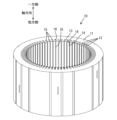
- FIG. 1 is a perspective view of the stator of the first embodiment cut in the axial direction.
- FIG. 2 is a perspective view of the stator core.
- FIG. 3 is a cross-sectional view of a part of a cut surface of the stator taken in a direction perpendicular to the axial direction, as seen from the other axial side.
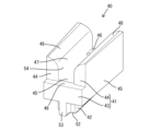
- FIG. 4 is a perspective view of the first positioning component viewed from one side in the axial direction.
- FIG. 5 is a perspective view of the first positioning component viewed from the other axial side.
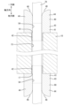
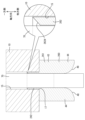
- FIG. 6 is a cross-sectional view showing how the coil segment is inserted into the slot.
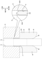
- FIG. 7 is a cross-sectional view showing a state in which the coil segment is positioned by the first positioning component and the second positioning component.
- FIG. 1 is a perspective view of the stator of the first embodiment cut in the axial direction.
- FIG. 2 is a perspective view of the stator core.
- FIG. 3 is a cross-sectional view
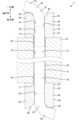
- FIG. 8 is a cross-sectional view showing a state in which the coil segment is bent along an inclined surface.
- FIG. 9 is an explanatory diagram for explaining a first other form of the second positioning component.
- FIG. 10 is an explanatory diagram for explaining a second other form of the second positioning component.
- the stator core has a plurality of slots arranged in an annular shape and passing through the stator core in the axial direction
- the coil has an insertion portion passing through the slot
- the insulating resin has a continuous filling part that is continuously filled between the inner wall of the slot and the insertion part in the axial center part of the slot
- the positioning component positions the insertion part in a state in which at least a part of the positioning component is inserted between an inner wall of the slot and the insertion part on one side in the axial direction than the continuous filling part.
- the heat of the coil can be easily dissipated.
- the insertion part is positioned with at least a part of the positioning component inserted between the inner wall of the slot and the insertion part, the position of the insertion part within the slot is easily stabilized, and as a result, The heat dissipation performance of the insertion part is easily stabilized.
- the insertion portion is positioned both inside and outside the slot, the position of the insertion portion is more likely to be stabilized.
- a second positioning component is provided on the other side of the continuous filling portion in the axial direction and positions the insertion portion in a state where at least a portion thereof is inserted between the inner wall of the slot and the insertion portion;
- the insertion portion is positioned on both sides in the axial direction, the position of the insertion portion can be more easily stabilized.
- the coil has an extension part extending from one end of the insertion part via a bent part,
- the stator according to any one of [1] to [3], wherein the positioning component has an inclined surface along the extension portion.
- the displacement of the extension portion is regulated by the inclined surface, so the attitude of the coil is more likely to be stabilized.
- a method for manufacturing a stator comprising an annular stator core and a coil segment, the stator core having a plurality of slots arranged in an annular shape and passing through the stator core in the axial direction, arranging a jig so as to cover at least a portion of an opening edge on one side of the slot in the axial direction; an insertion step of inserting the coil segment into the slot from the one side in the axial direction after arranging the jig;
- a method for manufacturing a stator comprising: a filling step of continuously filling an insulating resin between an inner wall of the slot and the coil segment in a central portion of the slot in the axial direction.
- the jig can easily prevent the insulating resin from leaking to the outside from the opening on one side of the slot in the axial direction.
- the jig includes a base disposed at the one end of the stator core in the axial direction, and a protrusion protruding from the base in a cylindrical shape and into which the coil segment is passed. death,
- the outer circumferential surface of the protruding portion has an outer circumferential tapered surface that is tapered toward the protruding end;
- the outer circumferential tapered surface is formed on the protruding end side of the protruding part, even if the coil segment is slightly shifted when passing the coil segment inside the protruding part, the outer circumferential tapered surface allows the coil segment to protrude. guided inside the section. Therefore, with this configuration, it is easy to insert the protrusion of the jig into the slot.
- the second jig has a second base disposed at the other end of the stator core in the axial direction, and a second protrusion protruding from the second base in a cylindrical shape,
- the inner circumferential surface of the second protruding portion has an inner circumferential tapered surface formed such that the hole in the second protruding portion widens toward the protruding end;
- the second jig is attached to the coil segment by inserting the second jig into the coil segment from the protruding end side of the second protrusion part [5] to [7].
- the jig can easily prevent the insulating resin from leaking to the outside of the slot on both sides in the axial direction. Moreover, since the inner circumferential surface of the second protruding part has an inner circumferential tapered surface, even if the coil segment is slightly shifted when passing the coil segment inside the second protruding part, the inner circumferential tapered surface allows the coil segment to move into the second protruding part. guided inside the protrusion. Therefore, according to this configuration, it is easy to attach the second jig to the coil segment.
- the outer circumferential surface of the second protrusion has a second outer circumferential tapered surface that is tapered toward the protruding end; Furthermore, a second arranging step of arranging the second jig at the other end of the stator core in the axial direction by inserting the second protrusion into the slot from the protrusion end side [ 8] The method for manufacturing a stator according to item 8.
- the second protruding portion since the second protruding portion has the second outer circumferential tapered surface formed on the protruding end side, when the second protruding portion is inserted into the slot from the protruding end side, the second protruding portion may be slightly bent. Even if it deviates, it is guided into the slot by the second outer peripheral tapered surface. Therefore, according to this configuration, it is easy to insert the second jig into the slot. In other words, since the inner circumferential tapered surface and the second outer circumferential tapered surface are formed on the protruding end side of the second protrusion, it is easy to attach the second jig to the coil segment, and the second jig can be inserted into the slot. Easy to insert.
- the base of the jig has an inclined surface that guides the coil segment into the protrusion,
- the inclined surface that guides the coil segment can be used for bending the coil segment.
- the stator 1 of the first embodiment is used as a component of a rotating electric machine (specifically, a motor). As shown in FIG. 1, the stator 1 has an annular shape, more specifically an annular shape.
- the stator 1 includes a stator core 10, a coil 20, an insulating resin 30 (see FIG. 3), a first positioning component 40, and a second positioning component 60. Note that the insulating resin 30 is omitted in FIG. 1.
- the stator core 10 has an annular shape, more specifically an annular shape.
- the radial direction of stator core 10 will be referred to as the radial direction
- the axial direction of stator core 10 will be referred to as the axial direction
- the circumferential direction of stator core 10 will be referred to as the circumferential direction.
- the stator core 10 has a yoke part 11 and a teeth part 12, as shown in FIGS. 2 and 3.
- the yoke portion 11 has an annular shape, more specifically an annular shape.
- a plurality of teeth portions 12 are arranged in a ring shape along the inner circumferential surface of the yoke portion 11 .
- the respective teeth portions 12 are arranged at intervals from each other in the circumferential direction.
- Each tooth portion 12 protrudes radially inward from the inner circumferential surface of the yoke portion 11.
- Each tooth portion 12 has a wall shape along the radial direction and the axial direction.
- Each tooth portion 12 includes a tooth main body 13 having a wall shape along the radial direction and the axial direction, and a tooth tension extending from the distal end portion (in other words, the inner end portion in the radial direction) of the tooth main body 13 to both sides in the circumferential direction. It has an exit part 14.
- the stator core 10 may be, for example, a laminated steel plate manufactured by laminating a plurality of electromagnetic steel plates (for example, silicon steel plates) in the thickness direction, or a powdered powder formed by press-forming insulation-coated magnetic particles. It may be a magnetic core.
- the stator core 10 has a plurality of slots 15, as shown in FIG.
- the slots 15 are arranged in a ring. Slot 15 passes through stator core 10 in the axial direction.
- the slot 15 has a first opening 16, a second opening 17, and a third opening 18, as shown in FIGS. 2 and 8.
- the first opening 16 is formed on one surface of the stator core 10 in the axial direction.
- the second opening 17 is formed on the other axial surface of the stator core 10 .
- the third opening 18 is formed on the radially inner surface of the stator core 10.
- the third opening 18 is continuous with the first opening 16 and the second opening 17.
- the slot 15 is constituted by two adjacent teeth portions 12.
- the slot 15 is defined by the teeth portions 12 on both sides in the circumferential direction, and by the yoke portion 11 on the outer surface in the radial direction.
- the coil 20 may have distributed winding or concentrated winding. As shown in FIG. 1, the coil 20 passes through the slot 15 and is wound around the teeth 12.
- the coil 20 has a rectangular cross section cut in a direction perpendicular to the length direction.
- the coil 20 includes a core wire forming a conductive path and a covering portion covering the core wire.
- the core wire is a conductor.
- the core wire is a flat wire, and has a rectangular cross section cut in a direction perpendicular to the length direction.
- the covering portion forms an insulating layer.
- the material of the covering portion is not particularly limited. In this embodiment, the covering portion is a low dielectric constant enamel having a low dielectric constant.
- the covering portion may be made mainly of a thermosetting resin such as polyvinyl formal, thermosetting polyurethane, thermosetting acrylic, epoxy, thermosetting polyester, thermosetting polyesterimide, aromatic polyamide, thermosetting polyamideimide, thermosetting polyimide, etc. good. Further, the covering portion may be mainly composed of a thermoplastic resin such as polyetherimide, polyphenylene ether, polyether sulfone, polyphenylene sulfide, polyether ether ketone, or thermoplastic polyimide.
- the "main component” is the component with the highest content, for example, 50% by mass or more.
- the coil 20 has an insertion portion 21 that passes through the slot 15.
- the coil 20 includes a first extending portion 23 extending from one end of the insertion portion 21 via a first bending portion 22 and a first extending portion 23 extending from the other end of the insertion portion 21 via a second bending portion 24. 2 extending portions 25.
- the first bent portion 22 corresponds to an example of a “bent portion”.
- the first extending portion 23 corresponds to an example of an “extending portion”.
- the insulating resin 30 is filled in the slot 15.
- the slots 15 are shown as slots 15A and 15B.
- the insulating resin 30 is omitted inside the slot 15A.
- the inside of the slot 15B is shown filled with insulating resin 30.
- the insulating resin 30 has a continuous filling portion 31 that is continuously filled between the inner wall of the slot 15B (slot 15) and the insertion portion 21 in the axial center of the stator core 10.
- the continuous filling portion 31 is filled continuously in the axial direction except for both ends within the slot 15B (slot 15). According to this configuration, since no insulating paper is interposed between the inner wall of the slot 15 and the insertion part 21 in the continuous filling part 31, the heat of the coil 20 can be easily released.
- the first positioning component 40 corresponds to an example of a "positioning component” and corresponds to an example of a "jig.”
- the first positioning component 40 has insulating properties and is made of, for example, resin or ceramic.
- the first positioning component 40 has an annular shape, as shown in FIGS. 4 and 5.
- the first positioning component 40 has a base 41 and a protrusion 42 .
- the base 41 has an annular base 43 and an overhang 44.
- the annular base 43 has an annular shape.
- the annular base 43 has a pair of long sides 45 and a pair of short sides 46 .
- the pair of longitudinal portions 45 extend linearly parallel to each other.
- the pair of longitudinal portions 45 extend in the radial direction.
- the short side portion 46 is shorter than the long side portion 45.
- the pair of short side portions 46 extend linearly parallel to each other.
- the pair of short side portions 46 extend along a direction perpendicular to the long side portion 45 .
- the pair of short side portions 46 extend along the circumferential direction.
- the pair of long sides 45 and the pair of short sides 46 have an annular shape as a whole.
- the overhanging portion 44 overhangs from the base 41 to one side in the axial direction.
- the projecting portion 44 projects from each of the pair of longitudinal portions 45 toward one side in the axial direction.
- the projecting portions 44 form a pair.
- Each of the pair of projecting portions 44 has opposing surfaces 47 that face each other and an inclined surface 48 .
- the pair of opposing surfaces 47 face each other in the circumferential direction.
- the opposing surface 47 is a surface that extends along the axial direction and the radial direction. At least a portion of the opposing surface 47 is flush with the inner circumferential surface of the annular base 43 (more specifically, the surface where the pair of longitudinal portions 45 face each other).
- the pair of inclined surfaces 48 are inclined so that the distance between them increases toward the projecting side (one side in the axial direction) of the projecting portion 44 .
- the radially inner ends of the pair of projecting portions 44 are arranged radially inward than the inner circumferential surface of the annular base 43 and radially inner than the inner circumferential surface of the protruding portion 42.
- the radially outer ends of the pair of projecting portions 44 are arranged radially outward than the inner circumferential surface of the annular base 43 and radially outward than the inner circumferential surface of the protruding portion 42. .
- the radially inner end portions of the pair of opposing surfaces 47 and the pair of inclined surfaces 48 are arranged radially inner than the inner circumferential surface of the annular base 43 and radially inner than the inner circumferential surface of the protrusion 42. It is located in The radially outer ends of the pair of opposing surfaces 47 and the pair of inclined surfaces 48 are arranged radially outer than the inner circumferential surface of the annular base 43 and radially outer than the inner circumferential surface of the protrusion 42. It is located in
- the protrusion 42 protrudes in a cylindrical shape from the base 41 to the side opposite to the protrusion 44 (the other side in the axial direction).
- the protruding portion 42 protrudes in a cylindrical shape from the inner peripheral portion of the cylindrical base portion 41 .
- the protrusion 42 has a rectangular tube shape.
- the protrusion 42 has a pair of long plate parts 50 and a pair of short plate parts 51.
- the pair of long plate portions 50 extend linearly parallel to each other.
- the pair of long plate portions 50 extend along the radial direction.
- the short plate portion 51 is shorter than the long plate portion 50.
- the pair of short plate portions 51 extend linearly parallel to each other.
- the pair of short plate portions 51 extend along a direction perpendicular to the long plate portion 50.
- the pair of short plate portions 51 extend along the circumferential direction.
- the pair of long plate parts 50 and the pair of short plate parts 51 have a cylindrical shape as a whole (more specifically, a rectangular tube shape).
- the inner circumferential surface of the protrusion 42 is continuous with the inner circumferential surface of the base 41 (annular base 43) without any step.
- the outer circumferential surface of the protruding portion 42 has an outer circumferential tapered surface 52 that is tapered toward the protruding end.
- the first positioning component 40 has an inner protrusion 53 that protrudes radially inward from the outer peripheral surface of the protrusion 42 . As shown in FIG. 3, the inner protrusion 53 is disposed in the gap between the tooth protrusions 14 in the circumferential direction.
- the first positioning component 40 has a pair of positioning surfaces 54, as shown in FIGS. 4 and 5.
- the pair of positioning surfaces 54 position the insertion portion 21 in the circumferential direction.
- the pair of positioning surfaces 54 include a pair of opposing surfaces 47, an inner circumferential surface of the annular base 43 (more specifically, mutually opposing surfaces of the pair of longitudinal portions 45), and an inner circumferential surface of the protrusion 42 (more specifically, the opposing surfaces of the pair of longitudinal portions 45). Specifically, it is constituted by two opposing surfaces of a pair of long plate parts 50.
- the second positioning component 60 corresponds to an example of a "second jig." Since the second positioning component 60 has the same form as the first positioning component 40 in this embodiment, detailed description thereof will be omitted.
- the first positioning component 40 is arranged so that the protruding part 42 is inserted between the inner wall of the slot 15 and the insertion part 21 on one side of the continuous filling part 31 in the axial direction. is being positioned.
- the protrusions 42 position the insertion portion 21 in a state that they are inserted between the inner wall of the slot 15 and the insertion portion 21 on both sides of the insertion portion 21 .
- the protruding portion 42 enters between the innermost insertion portion 21 and the outermost insertion portion 21 of the plurality of insertion portions 21 arranged side by side along the radial direction, and the inner wall of the slot 15.
- the insertion portion 21 is positioned in this state.
- the insertion portion 21 is positioned with the protrusion 42 of the first positioning component 40 inserted between the inner wall of the slot 15 and the insertion portion 21, the position of the insertion portion 21 within the slot 15 is adjusted. It is easy to stabilize, and as a result, the heat dissipation performance of the insertion portion 21 via the insulating resin 30 is easy to stabilize.
- the first positioning component 40 is arranged both inside and outside the slot 15 in the axial direction, and positions the insertion portion 21 both inside and outside the slot 15.
- the inner circumferential surface of the protruding portion 42 of the first positioning component 40 positions the insertion portion 21 inside the slot 15, and the inner circumferential surface of the annular base 43 and the pair of protruding portions 44 A pair of opposing surfaces 47 position the insertion portion 21 outside the slot 15. According to this configuration, since the insertion portion 21 is positioned both inside and outside the slot 15, the position of the insertion portion 21 is more likely to be stabilized.
- the protrusion 42 connects the inner wall of the slot 15 and the insertion part 21 on the other side of the continuous filling part 31 in the axial direction, similar to the first positioning component 40.
- the insertion portion 21 is positioned in a state where it is inserted between the two.
- the insertion portion 21 is positioned by a first positioning component 40 and a second positioning component 60. According to this configuration, since the insertion portion 21 is positioned on both sides in the axial direction, the position of the insertion portion 21 is more likely to be stabilized.
- the inclined surface 48 of the first positioning component 40 is arranged along the first extending portion 23 of the coil 20, as shown in FIG.
- the inclined surface 48 of the second positioning component 60 is arranged along the second extending portion 25 of the coil 20 . According to this configuration, the displacement of the first extending portion 23 is regulated by the inclined surface 48 of the first positioning component 40, and the displacement of the second extending portion 25 is regulated by the inclined surface 48 of the second positioning component 60. Therefore, the attitude of the coil 20 is more likely to be stabilized.
- a plurality of (four in this embodiment) insertion portions 21 are arranged within one slot 15.
- the plurality of insertion portions 21 are arranged in a line in the radial direction within one slot 15 .
- the method for manufacturing stator 1 includes a first arrangement step, an insertion step, an attachment step, a second arrangement step, a filling step, a bending step, and a welding step.
- the first positioning component 40 is placed so as to cover at least a portion of the opening edge on one side of the slot 15 in the axial direction (see FIG. 6).
- the first positioning component 40 is inserted into the slot 15 from the protruding end side of the protrusion 42 .
- An outer peripheral tapered surface 52 is formed on the protruding end side of the protruding portion 42 . Therefore, even if the protrusion 42 is slightly deviated when inserted into the slot 15, the protrusion 42 will be guided into the slot 15. Therefore, with this configuration, it is easy to insert the protrusion 42 of the first positioning component 40 into the slot 15.
- the base 41 of the first positioning component 40 is arranged at one end of the stator core 10 in the axial direction.
- the first positioning component 40 is arranged so as to close an opening (first opening 16) on one side of the slot 15 in the axial direction.
- the pair of inclined surfaces 48 of the first positioning component 40 are arranged on one side of the protrusion 42 in the axial direction. According to this configuration, even if the coil segment 70 is slightly displaced when passing the coil segment 70 inside the protrusion 42 from one side in the axial direction, it is guided into the interior of the protrusion 42 by the inclined surface 48 . Therefore, with this configuration, it is easy to pass the coil segment 70 into the protrusion 42 from one side in the axial direction.
- the coil segment 70 is a component that constitutes the coil 20. Coil segment 70 has a straight shape.
- the coil segment 70 is inserted into the slot 15 from one side in the axial direction (see FIG. 6). According to this configuration, it is easy to insert the coil segment 70 into the slot 15 without contacting the stator core 10. Therefore, even if there is a burr at the opening end of the slot 15, it is easy to prevent the covering part of the insertion part 21 from being caught and peeled off.
- the coil segment 70 is inserted into the slot 15 through the inside of the cylindrical protrusion 42 from one side in the axial direction.
- the coil segment 70 passes between the pair of inclined surfaces 48 and into the cylindrical base 41 .
- the pair of inclined surfaces 48 are inclined so that the distance from each other increases toward one side in the axial direction.
- the second positioning component 60 is attached to the coil segment 70 inserted into the slot 15 in the insertion step from the other side in the axial direction (see FIG. 7). That is, in the attachment process, the second positioning component 60 is attached to the coil segment 70 that comes out from the opening (second opening 17) on the other side of the slot 15 in the axial direction. In the attachment process, the coil segment 70 is passed through the cylindrical protrusion 42 of the second positioning component 60 . The second positioning element 60 is attached to the coil segment 70 in an opposite orientation to the first positioning element 40 .
- the second positioning component 60 is placed so as to cover at least a portion of the opening edge on the other axial side of the slot 15 (see FIG. 7).
- the second positioning component 60 is inserted into the slot 15 from the protruding end side of the protrusion 42 .
- An outer peripheral tapered surface 52 is formed on the protruding end side of the protruding portion 42 . Therefore, even if the protrusion 42 is slightly deviated when inserted into the slot 15, the protrusion 42 will be guided into the slot 15. Therefore, with this configuration, it is easy to insert the protrusion 42 of the second positioning component 60 into the slot 15.
- the base portion 41 of the second positioning component 60 is arranged at the other end of the stator core 10 in the axial direction.
- the second positioning component 60 is arranged so as to close the opening (second opening 17) on the other side of the slot 15 in the axial direction.
- the pair of inclined surfaces 48 of the second positioning component 60 are arranged on the other side of the protrusion 42 in the axial direction.
- the insulating resin 30 is continuously filled between the inner wall of the slot 15 and the coil segment 70 at the axial center of the slot 15 (see FIG. 8). Since the insulating resin 30 is continuously filled between the inner wall of the slot 15 and the coil segment 70, the heat of the coil segment 70 is easily dissipated through the insulating resin 30, and as a result, the heat dissipation performance of the coil 20 is improved. can be improved.
- the opening (first opening 16) on one side of the slot 15 in the axial direction is closed by the first positioning component 40.
- the opening on the other axial side of the slot 15 (second opening 17) is closed by a second positioning component 60.
- the radially inner opening (third opening 18) of the slot 15 is closed by a separate member except for the resin injection part. Then, the insulating resin 30 is filled into the slot 15 from the third opening 18 .
- the first positioning component 40 and the second positioning component 60 can easily prevent the insulating resin 30 from leaking from both sides of the slot 15 in the axial direction.
- the filling process is performed while the coil segment 70 is positioned by the first positioning component 40 and the second positioning component 60. According to this configuration, when the insulating resin 30 is solidified, the coil segment 70 is easily arranged at an appropriate position.
- one end side of the coil segment 70 is bent along the inclined surface 48 of the first positioning component 40 (see FIG. 8). As a result, the first extending portion 23 is formed. According to this configuration, the inclined surface 48 that guides the coil segment 70 can be used to bend the coil segment 70. Further, in the bending step, the other end side of the coil segment 70 is bent along the inclined surface 48 of the second positioning component 60. As a result, the second extending portion 25 is formed.
- the first extended portion 23 of the coil segment 70 is welded to another coil component (for example, the first extended portion 23 of another coil segment 70). Further, in the welding process, the second extending portion 25 of the coil segment 70 is welded to another coil component (for example, the second extending portion 25 of another coil segment 70).
- the stator 1 is manufactured through these steps.
- the second positioning component 260 of the second embodiment corresponds to an example of a "second jig".
- the second positioning component 260 has insulating properties and is made of, for example, resin or ceramic.
- the second positioning component 260 has an annular shape.
- the second positioning component 260 includes a second base 261 disposed at the other end of the stator core 10, and a second protrusion 262 that protrudes in a cylindrical shape from the second base 261. have
- the second base 261 has the same form as the base 41 of the first embodiment.
- the second protrusion 262 protrudes in a cylindrical shape from the second base 261 to the side opposite to the protrusion 44 side (the other side in the axial direction).
- the second protruding portion 262 protrudes in a cylindrical shape from the inner peripheral portion of the cylindrical second base portion 261 .
- the second protrusion 262 has a rectangular tube shape.
- the inner circumferential surface of the second protrusion 262 is continuous with the inner circumferential surface of the second base 261 (annular base 43) without any step.
- the inner circumferential surface of the second protruding portion 262 has an inner circumferential tapered surface 262A formed so that the hole in the second protruding portion 262 widens toward the protruding end.
- the second positioning component 260 differs from the second positioning component 60 (first positioning component 40) of the first embodiment in that it has an inner tapered surface 262A and does not have an outer tapered surface 52, and in other respects. Common.
- the method for manufacturing the stator according to the second embodiment is similar to the method for manufacturing the stator 1 according to the first embodiment, and includes a first arrangement step, an insertion step, an attachment step, a second arrangement step, a filling step, and a bending step. and a welding process.
- the second positioning component 260 is attached to the coil segment 70 inserted into the slot 15 in the insertion process from the other side in the axial direction.
- the second positioning component 260 is attached to the coil segment 70 by inserting the second positioning component 260 through the coil segment 70 from the protruding end side of the second protrusion 262 .
- the inner circumferential surface of the second protruding part 262 has the inner circumferential tapered surface 262A, even if the coil segment 70 is slightly displaced when passing the coil segment 70 inside the second protruding part 262, The coil segment 70 is guided into the second protrusion 262 by the circumferential tapered surface 262A. Therefore, according to this configuration, it is easy to attach the second positioning component 260 to the coil segment 70.
- the second positioning component of the third embodiment differs from the positioning component of the second embodiment in that it has not only an inner tapered surface but also a second outer tapered surface, but is common in other respects.
- the same components as those in the first embodiment are denoted by the same reference numerals, and detailed description thereof will be omitted.
- the second positioning component 360 of the third embodiment corresponds to an example of a "second jig".
- the second positioning component 360 has insulating properties and is made of, for example, resin or ceramic.
- the second positioning component 360 has an annular shape.
- the second positioning component 360 includes a second base 361 disposed at the other end of the stator core 10, and a second protrusion 362 that protrudes in a cylindrical shape from the second base 361.
- the second base 361 has the same form as the base 41 of the first embodiment.
- the second protruding portion 362 protrudes in a cylindrical shape from the second base portion 361 to the side opposite to the projecting portion 44 side (the other side in the axial direction).
- the second protruding portion 362 protrudes in a cylindrical shape from the inner peripheral portion of the cylindrical second base portion 361 .
- the second protrusion 362 has a rectangular tube shape.
- the inner circumferential surface of the second protrusion 362 is continuous with the inner circumferential surface of the second base 361 (annular base 43) without any step.
- the inner circumferential surface of the second protruding portion 362 has an inner circumferential tapered surface 362A formed so that the hole in the second protruding portion 362 widens toward the protruding end.
- the outer circumferential surface of the second protruding portion 362 has a second outer circumferential tapered surface 362B that is tapered toward the protruding end.
- the second positioning component 360 is different from the second positioning component 60 (first positioning component 40) of the first embodiment in that it has an inner tapered surface 362A and a second outer tapered surface 362B instead of the outer tapered surface 52. are different and have other points in common.
- the method for manufacturing the stator according to the third embodiment is similar to the method for manufacturing the stator 1 according to the first embodiment, and includes a first arrangement step, an insertion step, an attachment step, a second arrangement step, a filling step, and a bending step. and a welding process.
- the second positioning component 360 is arranged at the other axial end of the stator core 10 by inserting the second protrusion 362 into the slot 15 from the protrusion end side.
- the second outer peripheral tapered surface 362B is formed on the protruding end side of the second protruding part 362, when inserting the second protruding part 362 into the slot 15 from the protruding end side, the second outer peripheral tapered surface 362B Even if the protrusion 362 is slightly displaced, it is guided into the slot 15 by the second outer peripheral tapered surface 362B. Therefore, according to this configuration, it is easy to insert the second positioning component 360 into the slot 15.
- the inner circumferential tapered surface 362A and the second outer circumferential tapered surface 362B are formed on the protruding end side of the second protruding portion 362, it is easy to attach the second positioning component 360 to the coil segment 70, and the second It is easy to insert the positioning component 360 into the slot 15.
- the first positioning component which is a part of the stator, was used as the first jig, and the second positioning component was used as the second jig.
- the stator may be manufactured using a jig that is not a part of the stator.
- the first positioning component may have the same form as the second positioning component.
- the first positioning component may have the same form as the second positioning component.
Landscapes
- Engineering & Computer Science (AREA)
- Power Engineering (AREA)
- Manufacturing & Machinery (AREA)
- Manufacture Of Motors, Generators (AREA)
- Insulation, Fastening Of Motor, Generator Windings (AREA)
Abstract
Description
環状のステータコアと、コイルと、絶縁樹脂と、位置決め部品と、を備え、
前記ステータコアは、環状に並び、前記ステータコアを軸方向に貫通する複数のスロットを有し、
前記コイルは、前記スロット内を通る挿通部を有し、
前記絶縁樹脂は、前記スロット内の前記軸方向の中央部において、前記スロットの内壁と前記挿通部との間で連続的に充填される連続充填部を有し、
前記位置決め部品は、前記連続充填部よりも前記軸方向の一方側において、少なくとも一部が前記スロットの内壁と前記挿通部との間に入り込んだ状態で前記挿通部を位置決めする。
環状のステータコアと、コイルセグメントと、を備え、前記ステータコアは、環状に並び、前記ステータコアを軸方向に貫通する複数のスロットを有するステータの製造方法であって、
前記スロットの前記軸方向の一方側の開口縁の少なくとも一部を覆うように治具を配置する配置工程と、
前記治具を配置した後に、前記スロット内に前記軸方向の前記一方側から前記コイルセグメントを挿入する挿入工程と、
前記スロット内の前記軸方向の中央部において、前記スロットの内壁と前記コイルセグメントとの間で絶縁樹脂を連続的に充填する充填工程と、を含む。
以下では、本開示の実施形態が列記されて例示される。
前記ステータコアは、環状に並び、前記ステータコアを軸方向に貫通する複数のスロットを有し、
前記コイルは、前記スロット内を通る挿通部を有し、
前記絶縁樹脂は、前記スロット内の前記軸方向の中央部において、前記スロットの内壁と前記挿通部との間で連続的に充填される連続充填部を有し、
前記位置決め部品は、前記連続充填部よりも前記軸方向の一方側において、少なくとも一部が前記スロットの内壁と前記挿通部との間に入り込んだ状態で前記挿通部を位置決めする
ステータ。
〔1〕に記載のステータ。
前記挿通部は、前記位置決め部品と前記第2位置決め部品とによって位置決めされる
〔1〕又は〔2〕に記載のステータ。
前記位置決め部品は、前記延設部に沿う傾斜面を有する
〔1〕から〔3〕のいずれかに記載のステータ。
前記スロットの前記軸方向の一方側の開口縁の少なくとも一部を覆うように治具を配置する配置工程と、
前記治具を配置した後に、前記スロット内に前記軸方向の前記一方側から前記コイルセグメントを挿入する挿入工程と、
前記スロット内の前記軸方向の中央部において、前記スロットの内壁と前記コイルセグメントとの間で絶縁樹脂を連続的に充填する充填工程と、を含む
ステータの製造方法。
〔5〕に記載のステータの製造方法。
前記突出部の外周面は、突出端に向かうにつれて先細りとなるように形成された外周テーパ面を有し、
前記配置工程では、前記突出部を突出端側から前記スロット内に挿入することで、前記治具を配置する〔5〕又は〔6〕に記載のステータの製造方法。
前記充填工程では、前記スロットの前記軸方向の前記一方側の開口を前記治具によって塞ぎ、前記軸方向の前記他方側の開口を前記第2治具によって塞ぎつつ、前記スロット内に前記絶縁樹脂を充填し、
前記第2治具は、前記ステータコアの前記軸方向の前記他方側の端部に配置される第2基部と、前記第2基部から筒状に突出した第2突出部と、を有し、
前記第2突出部の内周面は、突出端に向かうにつれて前記第2突出部内の孔が広がるように形成された内周テーパ面を有し、
前記取付工程では、前記コイルセグメントに対し、前記第2突出部の突出端側から前記第2治具を挿し通すことで、前記コイルセグメントに前記第2治具を取り付ける〔5〕から〔7〕のいずれかに記載のステータの製造方法。
更に、前記第2突出部を突出端側から前記スロット内に挿入することで、前記第2治具を前記ステータコアの前記軸方向の前記他方側の端部に配置させる第2配置工程を含む〔8〕に記載のステータの製造方法。
前記配置工程では、前記傾斜面が前記突出部よりも前記軸方向の前記一方側に配置されるように前記治具を配置する〔5〕から〔9〕のいずれかに記載のステータの製造方法。
1.ステータ1の構成
第1実施形態のステータ1は、回転電機(具体的には、モータ)の部品として使用される。ステータ1は、図1に示すように、環状、より具体的には円環状をなしている。ステータ1は、ステータコア10と、コイル20と、絶縁樹脂30(図3参照)と、第1位置決め部品40と、第2位置決め部品60と、を備える。なお、図1では、絶縁樹脂30が省略されている。
ステータ1の製造方法は、第1配置工程と、挿入工程と、取付工程と、第2配置工程と、充填工程と、曲げ工程と、溶接工程と、を含む。
第2実施形態では、第2位置決め部品の第1の他の形態について説明する。以下では、第1実施形態と同じ構成については同じ符号を付し、詳しい説明を省略する。
第3実施形態では、第2位置決め部品の第2の他の形態について説明する。第3実施形態の第2位置決め部品は、内周テーパ面だけでなく、第2外周テーパ面も有する点で、第2実施形態の位置決め部品とは異なり、その他の点で共通する。以下では、第1実施形態と同じ構成については同じ符号を付し、詳しい説明を省略する。
本開示は、上記記述及び図面によって説明した実施形態に限定されるものではない。例えば、上述又は後述の実施形態の特徴は、矛盾しない範囲であらゆる組み合わせが可能である。また、上述の実施形態のいずれの特徴も、必須のものとして明示されていなければ省略することもできる。
10 :ステータコア
11 :ヨーク部
12 :ティース部
13 :ティース本体
14 :ティース張出部
15 :スロット
15A :スロット
15B :スロット
16 :第1開口
17 :第2開口
18 :第3開口
20 :コイル
21 :挿通部
22 :第1屈曲部(屈曲部)
23 :第1延設部(延設部)
24 :第2屈曲部
25 :第2延設部
30 :絶縁樹脂
31 :連続充填部
40 :第1位置決め部品(位置決め部品、治具)
41 :基部
42 :突出部
43 :環状基部
44 :張出部
45 :長手部
46 :短手部
47 :対向面
48 :傾斜面
50 :長板部
51 :短板部
52 :外周テーパ面
53 :内側突出部
54 :位置決め面
60 :第2位置決め部品(第2治具)
70 :コイルセグメント
260 :第2位置決め部品(第2治具)
261 :第2基部
262 :第2突出部
262A :内周テーパ面
360 :第2位置決め部品(第2治具)
361 :第2基部
362 :第2突出部
362A :内周テーパ面
362B :第2外周テーパ面
Claims (12)
- 環状のステータコアと、コイルと、絶縁樹脂と、位置決め部品と、を備え、
前記ステータコアは、環状に並び、前記ステータコアを軸方向に貫通する複数のスロットを有し、
前記コイルは、前記スロット内を通る挿通部を有し、
前記絶縁樹脂は、前記スロット内の前記軸方向の中央部において、前記スロットの内壁と前記挿通部との間で連続的に充填される連続充填部を有し、
前記位置決め部品は、前記連続充填部よりも前記軸方向の一方側において、少なくとも一部が前記スロットの内壁と前記挿通部との間に入り込んだ状態で前記挿通部を位置決めする
ステータ。 - 前記位置決め部品は、前記軸方向において前記スロットの内外にわたって配置され、前記スロットの内外の両方で前記挿通部を位置決めする
請求項1に記載のステータ。 - 前記連続充填部よりも前記軸方向の他方側において、少なくとも一部が前記スロットの内壁と前記挿通部との間に入り込んだ状態で前記挿通部を位置決めする第2位置決め部品を備え、
前記挿通部は、前記位置決め部品と前記第2位置決め部品とによって位置決めされる
請求項1又は請求項2に記載のステータ。 - 前記コイルは、前記挿通部の一端から屈曲部を介して延設された延設部を有し、
前記位置決め部品は、前記延設部に沿う傾斜面を有する
請求項3に記載のステータ。 - 前記コイルは、前記挿通部の一端から屈曲部を介して延設された延設部を有し、
前記位置決め部品は、前記延設部に沿う傾斜面を有する
請求項1又は請求項2に記載のステータ。 - 環状のステータコアと、コイルセグメントと、を備え、前記ステータコアは、環状に並び、前記ステータコアを軸方向に貫通する複数のスロットを有するステータの製造方法であって、
前記スロットの前記軸方向の一方側の開口縁の少なくとも一部を覆うように治具を配置する配置工程と、
前記治具を配置した後に、前記スロット内に前記軸方向の前記一方側から前記コイルセグメントを挿入する挿入工程と、
前記スロット内の前記軸方向の中央部において、前記スロットの内壁と前記コイルセグメントとの間で絶縁樹脂を連続的に充填する充填工程と、を含む
ステータの製造方法。 - 前記充填工程では、前記スロットの前記軸方向の前記一方側の開口を前記治具によって塞ぎつつ、前記スロット内に前記絶縁樹脂を充填する
請求項6に記載のステータの製造方法。 - 前記治具は、前記ステータコアの前記軸方向の前記一方側の端部に配置される基部と、前記基部から筒状に突出し内部に前記コイルセグメントが通される突出部と、を有し、
前記突出部の外周面は、突出端に向かうにつれて先細りとなるように形成された外周テーパ面を有し、
前記配置工程では、前記突出部を突出端側から前記スロット内に挿入することで、前記治具を配置する請求項6又は請求項7に記載のステータの製造方法。 - 前記挿入工程において前記スロット内に挿し通された前記コイルセグメントに対し、前記軸方向の他方側から第2治具を取り付ける取付工程を含み、
前記充填工程では、前記スロットの前記軸方向の前記一方側の開口を前記治具によって塞ぎ、前記軸方向の前記他方側の開口を前記第2治具によって塞ぎつつ、前記スロット内に前記絶縁樹脂を充填し、
前記第2治具は、前記ステータコアの前記軸方向の前記他方側の端部に配置される第2基部と、前記第2基部から筒状に突出した第2突出部と、を有し、
前記第2突出部の内周面は、突出端に向かうにつれて前記第2突出部内の孔が広がるように形成された内周テーパ面を有し、
前記取付工程では、前記コイルセグメントに対し、前記第2突出部の突出端側から前記第2治具を挿し通すことで、前記コイルセグメントに前記第2治具を取り付ける請求項8に記載のステータの製造方法。 - 前記第2突出部の外周面は、突出端に向かうにつれて先細りとなるように形成された第2外周テーパ面を有し、
更に、前記第2突出部を突出端側から前記スロット内に挿入することで、前記第2治具を前記ステータコアの前記軸方向の前記他方側の端部に配置させる第2配置工程を含む請求項9に記載のステータの製造方法。 - 前記治具の前記基部は、前記コイルセグメントを前記突出部の内部に誘導する傾斜面を有し、
前記配置工程では、前記傾斜面が前記突出部よりも前記軸方向の前記一方側に配置されるように前記治具を配置する請求項8に記載のステータの製造方法。 - 前記コイルセグメントを前記傾斜面に沿って曲げる曲げ工程を含む請求項11に記載のステータの製造方法。
Priority Applications (2)
| Application Number | Priority Date | Filing Date | Title |
|---|---|---|---|
| CN202380033983.6A CN119032496A (zh) | 2022-04-26 | 2023-04-05 | 定子及定子的制造方法 |
| US18/859,267 US20250266730A1 (en) | 2022-04-26 | 2023-04-05 | Stator and method for producing stator |
Applications Claiming Priority (2)
| Application Number | Priority Date | Filing Date | Title |
|---|---|---|---|
| JP2022-072387 | 2022-04-26 | ||
| JP2022072387A JP2023161806A (ja) | 2022-04-26 | 2022-04-26 | ステータ及びステータの製造方法 |
Publications (1)
| Publication Number | Publication Date |
|---|---|
| WO2023210282A1 true WO2023210282A1 (ja) | 2023-11-02 |
Family
ID=88518761
Family Applications (1)
| Application Number | Title | Priority Date | Filing Date |
|---|---|---|---|
| PCT/JP2023/014124 Ceased WO2023210282A1 (ja) | 2022-04-26 | 2023-04-05 | ステータ及びステータの製造方法 |
Country Status (4)
| Country | Link |
|---|---|
| US (1) | US20250266730A1 (ja) |
| JP (1) | JP2023161806A (ja) |
| CN (1) | CN119032496A (ja) |
| WO (1) | WO2023210282A1 (ja) |
Cited By (1)
| Publication number | Priority date | Publication date | Assignee | Title |
|---|---|---|---|---|
| WO2025197609A1 (ja) * | 2024-03-20 | 2025-09-25 | 株式会社オートネットワーク技術研究所 | ステータの製造方法及びステータ |
Citations (5)
| Publication number | Priority date | Publication date | Assignee | Title |
|---|---|---|---|---|
| JP2013094056A (ja) * | 2012-12-25 | 2013-05-16 | Denso Corp | 回転電機のステータの製造方法 |
| JP2017079563A (ja) * | 2015-10-22 | 2017-04-27 | トヨタ自動車株式会社 | 回転電機用ステータ |
| JP2018125924A (ja) * | 2017-01-30 | 2018-08-09 | 本田技研工業株式会社 | スロットコイル、回転電機のステータ、及び回転電機のステータの製造方法 |
| JP2018148765A (ja) * | 2017-03-09 | 2018-09-20 | 本田技研工業株式会社 | 回転電機のステータ |
| JP2020202611A (ja) * | 2019-06-06 | 2020-12-17 | トヨタ自動車株式会社 | 回転電機の製造方法 |
Family Cites Families (1)
| Publication number | Priority date | Publication date | Assignee | Title |
|---|---|---|---|---|
| JP2006223058A (ja) * | 2005-02-10 | 2006-08-24 | Toyota Motor Corp | ステータ構造 |
-
2022
- 2022-04-26 JP JP2022072387A patent/JP2023161806A/ja active Pending
-
2023
- 2023-04-05 CN CN202380033983.6A patent/CN119032496A/zh active Pending
- 2023-04-05 WO PCT/JP2023/014124 patent/WO2023210282A1/ja not_active Ceased
- 2023-04-05 US US18/859,267 patent/US20250266730A1/en active Pending
Patent Citations (5)
| Publication number | Priority date | Publication date | Assignee | Title |
|---|---|---|---|---|
| JP2013094056A (ja) * | 2012-12-25 | 2013-05-16 | Denso Corp | 回転電機のステータの製造方法 |
| JP2017079563A (ja) * | 2015-10-22 | 2017-04-27 | トヨタ自動車株式会社 | 回転電機用ステータ |
| JP2018125924A (ja) * | 2017-01-30 | 2018-08-09 | 本田技研工業株式会社 | スロットコイル、回転電機のステータ、及び回転電機のステータの製造方法 |
| JP2018148765A (ja) * | 2017-03-09 | 2018-09-20 | 本田技研工業株式会社 | 回転電機のステータ |
| JP2020202611A (ja) * | 2019-06-06 | 2020-12-17 | トヨタ自動車株式会社 | 回転電機の製造方法 |
Cited By (1)
| Publication number | Priority date | Publication date | Assignee | Title |
|---|---|---|---|---|
| WO2025197609A1 (ja) * | 2024-03-20 | 2025-09-25 | 株式会社オートネットワーク技術研究所 | ステータの製造方法及びステータ |
Also Published As
| Publication number | Publication date |
|---|---|
| US20250266730A1 (en) | 2025-08-21 |
| JP2023161806A (ja) | 2023-11-08 |
| CN119032496A (zh) | 2024-11-26 |
Similar Documents
| Publication | Publication Date | Title |
|---|---|---|
| CN101873023B (zh) | 电枢 | |
| JP5785863B2 (ja) | 電動機の固定子および永久磁石式回転電機 | |
| US10096420B2 (en) | Reactor | |
| JP7209264B2 (ja) | インシュレータ及びそれを備えたステータ、モータ | |
| KR20170007264A (ko) | 코어 케이스 유닛, 코일 부품 및 코일 부품의 제조 방법 | |
| EP3039773A2 (en) | Fixing method and fixing structure for fixing a coil insulator, stator using the same and rotating electrical machine using the same | |
| CN110164672B (zh) | 旋转变压器的定子构造以及旋转变压器 | |
| WO2016136384A1 (ja) | 電機子および回転電機 | |
| US9716414B2 (en) | Stator of rotating electric machine | |
| CN111628592B (zh) | 电能与机械能的转换器 | |
| CN101258661A (zh) | 定子铁芯、使用定子铁芯的电动机及定子铁芯的制造方法 | |
| JPH11122855A (ja) | ステータ用コイルボビンと電動機 | |
| WO2023210282A1 (ja) | ステータ及びステータの製造方法 | |
| US12573907B2 (en) | Stator having slots filled with resin for insulation | |
| WO2024048294A1 (ja) | ステータ、及びステータの製造方法 | |
| CN111540587B (zh) | 线圈装置 | |
| TWM586906U (zh) | 用於電動馬達之步進定子 | |
| WO2023210283A1 (ja) | ステータ及びステータの製造方法 | |
| JP7289102B2 (ja) | インシュレータ及びそれを備えたステータ、モータ | |
| US20210099040A1 (en) | Stator and motor | |
| JP6090044B2 (ja) | 回転電機ステータの製造方法及び回転電機ステータ | |
| JP7205454B2 (ja) | ステータ、ステータアッセンブリ、電気エネルギーと力学的エネルギーとの変換器 | |
| CN112640263A (zh) | 定子 | |
| JP2025144581A (ja) | ステータの製造方法及びステータ | |
| US20250219478A1 (en) | Stator and motor |
Legal Events
| Date | Code | Title | Description |
|---|---|---|---|
| 121 | Ep: the epo has been informed by wipo that ep was designated in this application |
Ref document number: 23793989 Country of ref document: EP Kind code of ref document: A1 |
|
| WWE | Wipo information: entry into national phase |
Ref document number: 202380033983.6 Country of ref document: CN |
|
| WWE | Wipo information: entry into national phase |
Ref document number: 18859267 Country of ref document: US |
|
| NENP | Non-entry into the national phase |
Ref country code: DE |
|
| 122 | Ep: pct application non-entry in european phase |
Ref document number: 23793989 Country of ref document: EP Kind code of ref document: A1 |
|
| WWP | Wipo information: published in national office |
Ref document number: 18859267 Country of ref document: US |