WO2023210207A1 - 電圧検出装置及び電池モジュール - Google Patents
電圧検出装置及び電池モジュール Download PDFInfo
- Publication number
- WO2023210207A1 WO2023210207A1 PCT/JP2023/010562 JP2023010562W WO2023210207A1 WO 2023210207 A1 WO2023210207 A1 WO 2023210207A1 JP 2023010562 W JP2023010562 W JP 2023010562W WO 2023210207 A1 WO2023210207 A1 WO 2023210207A1
- Authority
- WO
- WIPO (PCT)
- Prior art keywords
- voltage detection
- socket
- detection device
- holder
- plug
- Prior art date
- Legal status (The legal status is an assumption and is not a legal conclusion. Google has not performed a legal analysis and makes no representation as to the accuracy of the status listed.)
- Ceased
Links
Images


Classifications
-
- H—ELECTRICITY
- H01—ELECTRIC ELEMENTS
- H01M—PROCESSES OR MEANS, e.g. BATTERIES, FOR THE DIRECT CONVERSION OF CHEMICAL ENERGY INTO ELECTRICAL ENERGY
- H01M10/00—Secondary cells; Manufacture thereof
- H01M10/42—Methods or arrangements for servicing or maintenance of secondary cells or secondary half-cells
- H01M10/48—Accumulators combined with arrangements for measuring, testing or indicating the condition of cells, e.g. the level or density of the electrolyte
- H01M10/482—Accumulators combined with arrangements for measuring, testing or indicating the condition of cells, e.g. the level or density of the electrolyte for several batteries or cells simultaneously or sequentially
-
- G—PHYSICS
- G01—MEASURING; TESTING
- G01R—MEASURING ELECTRIC VARIABLES; MEASURING MAGNETIC VARIABLES
- G01R31/00—Arrangements for testing electric properties; Arrangements for locating electric faults; Arrangements for electrical testing characterised by what is being tested not provided for elsewhere
- G01R31/36—Arrangements for testing, measuring or monitoring the electrical condition of accumulators or electric batteries, e.g. capacity or state of charge [SoC]
- G01R31/396—Acquisition or processing of data for testing or for monitoring individual cells or groups of cells within a battery
-
- G—PHYSICS
- G01—MEASURING; TESTING
- G01R—MEASURING ELECTRIC VARIABLES; MEASURING MAGNETIC VARIABLES
- G01R31/00—Arrangements for testing electric properties; Arrangements for locating electric faults; Arrangements for electrical testing characterised by what is being tested not provided for elsewhere
- G01R31/36—Arrangements for testing, measuring or monitoring the electrical condition of accumulators or electric batteries, e.g. capacity or state of charge [SoC]
- G01R31/382—Arrangements for monitoring battery or accumulator variables, e.g. SoC
- G01R31/3835—Arrangements for monitoring battery or accumulator variables, e.g. SoC involving only voltage measurements
-
- H—ELECTRICITY
- H01—ELECTRIC ELEMENTS
- H01M—PROCESSES OR MEANS, e.g. BATTERIES, FOR THE DIRECT CONVERSION OF CHEMICAL ENERGY INTO ELECTRICAL ENERGY
- H01M10/00—Secondary cells; Manufacture thereof
- H01M10/42—Methods or arrangements for servicing or maintenance of secondary cells or secondary half-cells
- H01M10/425—Structural combination with electronic components, e.g. electronic circuits integrated to the outside of the casing
-
- H—ELECTRICITY
- H01—ELECTRIC ELEMENTS
- H01M—PROCESSES OR MEANS, e.g. BATTERIES, FOR THE DIRECT CONVERSION OF CHEMICAL ENERGY INTO ELECTRICAL ENERGY
- H01M10/00—Secondary cells; Manufacture thereof
- H01M10/42—Methods or arrangements for servicing or maintenance of secondary cells or secondary half-cells
- H01M10/48—Accumulators combined with arrangements for measuring, testing or indicating the condition of cells, e.g. the level or density of the electrolyte
-
- H—ELECTRICITY
- H01—ELECTRIC ELEMENTS
- H01M—PROCESSES OR MEANS, e.g. BATTERIES, FOR THE DIRECT CONVERSION OF CHEMICAL ENERGY INTO ELECTRICAL ENERGY
- H01M50/00—Constructional details or processes of manufacture of the non-active parts of electrochemical cells other than fuel cells, e.g. hybrid cells
- H01M50/20—Mountings; Secondary casings or frames; Racks, modules or packs; Suspension devices; Shock absorbers; Transport or carrying devices; Holders
- H01M50/204—Racks, modules or packs for multiple batteries or multiple cells
- H01M50/207—Racks, modules or packs for multiple batteries or multiple cells characterised by their shape
- H01M50/209—Racks, modules or packs for multiple batteries or multiple cells characterised by their shape adapted for prismatic or rectangular cells
-
- H—ELECTRICITY
- H01—ELECTRIC ELEMENTS
- H01M—PROCESSES OR MEANS, e.g. BATTERIES, FOR THE DIRECT CONVERSION OF CHEMICAL ENERGY INTO ELECTRICAL ENERGY
- H01M50/00—Constructional details or processes of manufacture of the non-active parts of electrochemical cells other than fuel cells, e.g. hybrid cells
- H01M50/50—Current conducting connections for cells or batteries
- H01M50/502—Interconnectors for connecting terminals of adjacent batteries; Interconnectors for connecting cells outside a battery casing
- H01M50/519—Interconnectors for connecting terminals of adjacent batteries; Interconnectors for connecting cells outside a battery casing comprising printed circuit boards [PCB]
-
- H—ELECTRICITY
- H01—ELECTRIC ELEMENTS
- H01M—PROCESSES OR MEANS, e.g. BATTERIES, FOR THE DIRECT CONVERSION OF CHEMICAL ENERGY INTO ELECTRICAL ENERGY
- H01M50/00—Constructional details or processes of manufacture of the non-active parts of electrochemical cells other than fuel cells, e.g. hybrid cells
- H01M50/50—Current conducting connections for cells or batteries
- H01M50/569—Constructional details of current conducting connections for detecting conditions inside cells or batteries, e.g. details of voltage sensing terminals
-
- Y—GENERAL TAGGING OF NEW TECHNOLOGICAL DEVELOPMENTS; GENERAL TAGGING OF CROSS-SECTIONAL TECHNOLOGIES SPANNING OVER SEVERAL SECTIONS OF THE IPC; TECHNICAL SUBJECTS COVERED BY FORMER USPC CROSS-REFERENCE ART COLLECTIONS [XRACs] AND DIGESTS
- Y02—TECHNOLOGIES OR APPLICATIONS FOR MITIGATION OR ADAPTATION AGAINST CLIMATE CHANGE
- Y02E—REDUCTION OF GREENHOUSE GAS [GHG] EMISSIONS, RELATED TO ENERGY GENERATION, TRANSMISSION OR DISTRIBUTION
- Y02E60/00—Enabling technologies; Technologies with a potential or indirect contribution to GHG emissions mitigation
- Y02E60/10—Energy storage using batteries
Definitions
- the present invention relates to a voltage detection device and a battery module.
- a battery module includes a plurality of battery cells, a housing, a wire harness, and a connector.
- the housing accommodates a plurality of battery cells.
- the connector is electrically connected to the plurality of battery cells via a wire harness.
- the connector is attached to the housing.
- the connector when the connector is attached to the housing, the connector is attached to the housing after a plurality of battery cells and wire harnesses are housed in the housing.
- an extra length of the wire harness is required to pull the wire harness out to the outside of the housing, which may reduce the workability for assembling the battery module.
- An example of the object of the present invention is to improve workability for assembling battery modules. Other objects of the invention will become apparent from the description herein.
- One aspect of the present invention is as follows. [1] a holding body; a plurality of voltage detection lines electrically connected to a plurality of battery cells and held by the holder; a connector electrically connected to the plurality of voltage detection lines and provided on the holder; A voltage detection device comprising: [2] The voltage detection device according to [1], wherein the connector is provided with a terminal hole through which at least a portion of an external terminal is inserted. [3] The voltage detection device according to [1] or [2], wherein a gap is provided through which at least a portion of an external connector connected to the connector is inserted. [4] The voltage detection device according to any one of [1] to [3], further comprising a mounting structure for mounting the holding body and the connector to each other.
- a holding body a holding body; a plurality of voltage detection lines electrically connected to a plurality of battery cells and held by the holder; a socket electrically connected to the plurality of voltage detection lines; Equipped with A voltage detection device, wherein at least a portion of the socket is embedded in a recess provided in the holder.
- a gap is provided between the socket and the recess.
- the plurality of battery cells are stacked in a predetermined first direction, The holding body is located on a second direction side perpendicular to the first direction in the plurality of battery cells, The voltage detection device according to [5] or [6], wherein the recess is provided on a surface of the holding body on a third direction side perpendicular to the first direction and the second direction. [8] the plurality of battery cells; [1] The voltage detection device according to any one of "7", A battery module comprising:
- FIG. 2 is a front perspective view of a battery module according to an embodiment.
- FIG. 2 is a diagram with the container removed from FIG. 1;
- FIG. 2 is an enlarged perspective view of a portion of the front voltage detection device according to the embodiment.
- FIG. 4 is a diagram with two sockets and a plug removed from FIG. 3;
- FIG. 3 is a rear perspective view of the socket according to the embodiment.
- 7 is an enlarged perspective view of the front portion of the front voltage detection device according to Modification 1.
- FIG. FIG. 7 is an enlarged perspective view of a front portion of a front voltage detection device according to a second modification.
- FIG. 7 is an enlarged perspective view of a portion of a front voltage detection device according to modification 3;
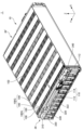
- FIG. 1 is a front perspective view of a battery module 1 according to an embodiment.
- FIG. 2 is a diagram from FIG. 1 with the container 20 removed.
- the X direction indicates the front-rear direction of the battery module 1.
- the tip side of the arrow indicating the X direction will be the rear side of the battery module 1.
- the base end side of the arrow indicating the X direction will be the front side of the battery module 1.
- the Y direction is perpendicular to the X direction.
- the Y direction indicates the left and right direction of the battery module 1.
- the tip side of the arrow indicating the Y direction will be the left side of the battery module 1.
- the base end side of the arrow indicating the Y direction will be the right side of the battery module 1.
- the Z direction is perpendicular to both the X direction and the Y direction.
- the Z direction indicates the vertical direction of the battery module 1.
- the tip side of the arrow indicating the Z direction is assumed to be the upper side of the battery module 1.
- the base end side of the arrow indicating the Z direction will be referred to as the lower side of the battery module 1.
- the relationships between the X direction, Y direction, and Z direction and the front-rear direction, left-right direction, and up-down direction of the battery module 1 are not limited to the above-mentioned example. These relationships differ depending on the actual arrangement of battery module 1.
- the battery module 1 includes a cell stack 10, a housing 20, a front voltage detection device 30, and a rear voltage detection device 30'.
- the cell stack 10 includes a plurality of cell groups 100G. Each cell group 100G includes a plurality of battery cells 100.
- the container 20 includes a front cover 210, a rear cover 220, a right cover 230, a left cover 240, a lower cover 250, and an upper cover 260.
- the front voltage detection device 30 includes a holder 310, a plurality of voltage detection lines 320, two sockets 330, and a terminal 340.
- a plurality of voltage detection tip portions 322 are provided at one end of the plurality of voltage detection lines 320 on the tab group 110 side, which will be described later.
- the plurality of battery cells 100 are stacked in the Y direction. When viewed from the Y direction, each battery cell 100 has a substantially rectangular shape.
- the longitudinal direction of each battery cell 100 is approximately parallel to the X direction.
- the lateral direction of each battery cell 100 is approximately parallel to the Z direction.
- the thickness direction of each battery cell 100 is approximately parallel to the Y direction.
- the structure of each battery cell 100 is not limited to this example.
- Each battery cell 100 has a battery element (not shown), an exterior material 102, a positive electrode tab 112, and a negative electrode tab 114.
- the exterior material 102 seals a battery element and an electrolytic solution (not shown).
- the battery element includes a plurality of positive electrodes (not shown) and a plurality of negative electrodes (not shown) alternately stacked in the Y direction, and a separator (not shown) located between the positive electrodes and negative electrodes adjacent to each other in the Y direction.
- the positive electrode tab 112 and the negative electrode tab 114 are pulled out from opposite sides of the exterior material 102 in the X direction.
- the positive electrode tab 112 is electrically connected to the plurality of positive electrodes described above.
- the positive electrode tab 112 is made of aluminum, for example.
- the negative electrode tab 114 is electrically connected to the plurality of negative electrodes described above.
- the negative electrode tab 114 is made of copper, for example.
- Each cell group 100G includes two battery cells 100 connected in parallel.
- the positive electrode tabs 112 pulled out from the two battery cells 100 included in each cell group 100G are oriented toward the same side in the X direction.
- the negative electrode tabs 114 pulled out from the two battery cells 100 included in each cell group 100G are oriented toward the same side in the X direction.
- the plurality of cell groups 100G are connected in series.
- Cell groups 100G adjacent to each other in the Y direction have a tab group 110 located in front or behind the cell group 100G.
- the tab group 110 includes two positive electrode tabs 112 pulled out from one side of the cell group 100G adjacent in the Y direction, and two negative electrode tabs 114 pulled out from the other side of the cell group 100G adjacent in the Y direction. There is.
- the two positive electrode tabs 112 and the two negative electrode tabs 114 are joined to each other by, for example, laser welding.
- the plurality of tab groups 110 located at the front of the cell stack 10 and the plurality of tab groups 110 located at the rear of the cell stack 10 are alternated in the Y direction.
- the cell group 100G located on the leftmost side and the cell group 100G located second from the left have the tab group 110 located in front of these cell groups 100G. There is. Further, the cell group 100G located second from the left and the cell group 100G located third from the left have a tab group 110 located behind these cell groups 100G.
- each cell group 100G may include three or more battery cells 100. Further, a plurality of single battery cells 100 may be connected in series.
- the container 20 includes a cell stack 10, a front voltage detection device 30, and a rear voltage detection device 30'.
- the front cover 210 covers the front of the cell stack 10 and the front voltage detection device 30.
- the rear cover 220 covers the rear of the cell stack 10 and the rear voltage detection device 30'.
- the right cover 230 covers the right side of the cell stack 10.
- the left cover 240 covers the left side of the cell stack 10.
- the lower cover 250 covers the lower part of the cell stack 10.
- the upper cover 260 covers the top of the cell stack 10.
- the holder 310 is provided in front of the cell stack 10.
- Holder 310 is made of resin, for example.
- the holder 310 integrally holds a plurality of voltage detection lines 320, a plurality of voltage detection tips 322, and two sockets 330. Therefore, by positioning the holder 310 with respect to the cell stack 10, the plurality of voltage detection lines 320 and the plurality of voltage detection tips 322 can be positioned. For example, by attaching the holder 310 to the container 20, the holder 310 is positioned with respect to the cell stack 10. When the holder 310 is positioned, each of the plurality of voltage detection tips 322 is located in front of each of the plurality of tab groups 110 located in front of the cell stack 10.
- the plurality of voltage detection lines 320 are, for example, wire harnesses. Each of the plurality of voltage detection lines 320 electrically connects each of the plurality of tab groups 110 and the socket 330. Specifically, one end of each of the plurality of voltage detection lines 320 is electrically connected to each of the plurality of tab groups 110 located in front of the cell stack 10 via each of the plurality of voltage detection tips 322. It is connected. Each voltage detection tip 322 is, for example, a conductive plate such as a metal plate. Each voltage detection tip 322 is joined to the front surface of each tab group 110 by, for example, laser welding. The other end of each of the plurality of voltage detection lines 320 is electrically connected to a socket 330.
- the terminal 340 is electrically connected to the positive electrode tab 112 pulled out forward from the rightmost battery cell 100.
- the cell stack 10 can be electrically connected to external equipment via the terminal 340.
- the rear voltage detection device 30' includes a holder (not shown), a plurality of voltage detection wires, a connector, and a terminal.
- a terminal of the rear voltage detection device 30' is electrically connected to a negative electrode tab 114 pulled out rearward from the battery cell 100 located on the leftmost side.
- FIG. 3 is an enlarged perspective view of a portion of the front voltage detection device 30 according to the embodiment.
- FIG. 4 is a diagram from FIG. 3 with two sockets 330 and plug 430 removed.
- FIG. 5 is a rear perspective view of the socket 330 according to the embodiment.
- the two sockets 330 and plug 430 will be described with reference to FIG. 3.
- a step 262 is provided at the front end of the upper cover 260. Due to the step 262, the front end of the upper cover 260 is located at a lower position in the Z direction than the rear part of the front end of the upper cover 260.
- the two sockets 330 shown in FIG. 3 are placed in the space formed by the step 262. Therefore, the volumetric efficiency of the battery module 1 can be improved.
- the plug 430 shown in FIG. 3 can be connected to the socket 330 on the left side shown in FIG.
- the plug 430 has a plurality of terminals and a plug cover 434 (not shown).
- the plurality of terminals of the plug 430 protrude toward the right.
- the plug cover 434 surrounds the plurality of terminals of the plug 430. Therefore, compared to the case where the plurality of terminals of the plug 430 are not surrounded by the plug cover 434, it is possible to make it difficult for foreign objects such as an operator's fingers or dust to come into contact with the plurality of terminals of the plug 430.
- the socket 330 on the left side shown in FIG. 3 has a body 332 and a socket cover 334. Some of the voltage detection lines 320 among the plurality of voltage detection lines 320 are electrically connected to the socket 330 on the left side shown in FIG. 3 . In the example shown in FIG. 3, some of the voltage detection lines 320 are connected to the socket 330 by passing through a tube 324 attached to the socket 330.
- the body 332 is provided with a plurality of terminal holes 332a. Terminals are embedded inside the plurality of terminal holes 332a. Therefore, in the socket 330 according to the embodiment, compared to a case where the terminal of the socket 330 protrudes to the outside, the terminal can be made less likely to come into contact with foreign objects such as a worker's finger or dust.
- Each of the plurality of terminals of the plug 430 is inserted into each of the plurality of terminal holes 332a in the Y direction. By inserting the plurality of terminals of the plug 430 into each of the plurality of terminal holes 332a in the Y direction, the socket 330 and the plug 430 are electrically connected.
- the socket cover 334 surrounds at least a portion of the body 332 with a gap 336 in between.
- the socket 330 and the plug 430 are connected to each other. Therefore, compared to the case where the gap 336 and the plug cover 434 are not provided, the mechanical connection between the socket 330 and the plug 430 can be made stronger.
- the gap 336 and the plug cover 434 may not be provided.
- the socket 330 and the plug 430 can be mechanically connected to each other by inserting each of the plurality of terminals of the plug 430 into each of the plurality of terminal holes 332a in the Y direction.
- the socket 330 on the right side shown in FIG. 3 has a similar configuration to the socket 330 on the left side shown in FIG.
- some voltage detection lines 320 are electrically connected to one socket 330
- other voltage detection lines 320 are electrically connected to the other socket 330. be able to. Therefore, the number of terminal holes 332a of each socket 330 can be reduced compared to the case where all the plurality of voltage detection lines 320 are electrically connected to a single socket 330.
- the terminal holes 332a of each socket 330 are arranged in the Z direction, the width of each socket 330 in the Z direction can be reduced. Therefore, the top surface of each socket 330 can be prevented from protruding above the top surface of the upper cover 260.
- the front voltage detection device 30 may have only one socket 330, or may have three or more sockets 330.
- the socket 330 on the right side shown in FIG. 3 is located more forward than the socket 330 on the left side shown in FIG. That is, the two sockets 330 shown in FIG. 3 are offset from each other in the X direction. Therefore, a space can be secured behind the left socket 330 shown in FIG. 3 for passing the plurality of voltage detection lines 320 connected to the right socket 330 shown in FIG. Therefore, compared to the case where the two sockets 330 shown in FIG. 3 are aligned in the X direction, the space in the Y direction for arranging the two sockets 330 shown in FIG. 3 can be made smaller.
- the layout of the socket 330 is not limited to this example.
- the two sockets 330 shown in FIG. 3 may be aligned in the X direction.
- FIGS. 4 and 5 A method for attaching the left socket 330 shown in FIG. 3 to the holder 310 will be described using FIGS. 4 and 5.
- a pair of locking grooves 352 are provided on the front surface of the holder 310.
- the pair of locking grooves 352 extend substantially parallel to the Y direction.
- a pair of locking portions 354 are provided on the rear surface of the socket cover 334.
- the pair of locking portions 354 extend substantially parallel to the Y direction.
- the pair of locking portions 354 can be inserted into the pair of locking grooves 352 from the left side of the pair of locking grooves 352 in the Y direction.
- the socket 330 is attached to the holder 310 by inserting the pair of locking portions 354 into the pair of locking grooves 352 from the left side of the pair of locking grooves 352 in the Y direction.
- the pair of locking grooves 352 and the pair of locking portions 354 form a mounting structure for attaching the holder 310 and the socket 330 on the left side shown in FIG. 3 to each other.
- the mounting structure is not limited to the example of the pair of locking grooves 352 and the pair of locking portions 354.
- the socket 330 on the right side shown in FIG. 3 is also attached to the holder 310 using the same mounting structure as the socket 330 on the left side shown in FIG.
- the above-described mounting structure that is, the pair of locking grooves 352 and the pair of locking portions 354 are located on the rear side of the socket 330. Therefore, when the plug cover 434 is inserted into the gap 336 in the Y direction, the mounting structure does not interfere with the plug cover 434. Therefore, there is no need to provide a notch in the plug cover 434 to avoid interference with the mounting structure. Therefore, a decrease in the strength of the plug cover 434 due to the notch can be suppressed. However, if necessary, the plug cover 434 may be provided with a notch.
- a socket 330 is provided on the holder 310. Therefore, after the front voltage detection device 30 is attached to the cell stack 10, the cell stack 10 and the front voltage detection device 30 can be housed in the container 20.
- the socket 330 is provided in the container 20
- the socket 330 is attached to the container 20 after the cell stack 10 is accommodated in the container 20.
- an extra length of the plurality of voltage detection lines 320 is required to draw the plurality of voltage detection lines 320 to the outside of the container 20.
- the socket 330 is a connector provided on the front voltage detection device 30, and the plug 430 is an external connector of the front voltage detection device 30.
- the connector provided on the front voltage detection device 30 may be a plug
- the external connector of the front voltage detection device 30 may be a socket.
- the workability for assembling the battery module 1 can be improved compared to the case where the above-mentioned plug is provided in the container 20.
- FIG. 6 is an enlarged perspective view of the front portion of the front voltage detection device 30A according to Modification 1.
- the front voltage detection device 30A according to Modification 1 is the same as the front voltage detection device 30 according to the embodiment except for the following points.
- At least a portion of the socket 330A is embedded in a recess 312A provided on the upper surface of the holder 310A.
- a gap 336A is provided between the outer surface of the socket 330A and the inner surface of the recess 312A.
- the plug 430A can be connected to the socket 330A from above the socket 330A. By inserting the plug cover 434A into the gap 336A in the Z direction, the socket 330A and the plug 430A are mechanically connected to each other. Therefore, in the first modification as well, it is possible to strengthen the mechanical connection between the socket 330A and the plug 430A, similarly to the embodiment.
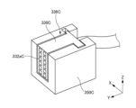
- FIG. 7 is an enlarged perspective view of the front portion of the front voltage detection device 30B according to Modification 2.
- the front voltage detection device 30B according to the second modification is the same as the front voltage detection device 30 according to the embodiment except for the following points.
- At least a portion of the socket 330B is embedded in a recess 312B provided on the front surface of the holder 310B.
- a gap 336B is provided between the outer surface of the socket 330B and the inner surface of the recess 312B.
- Plug 430B can be connected to socket 330B from the front of socket 330B. By inserting the plug cover 434B into the gap 336B in the X direction, the socket 330B and the plug 430B are mechanically connected to each other. Therefore, in the second modification as well, the mechanical connection between the socket 330B and the plug 430B can be strengthened similarly to the embodiment.
- FIG. 8 is an enlarged perspective view of a portion of a front voltage detection device 30C according to Modification 3.
- a forward voltage detection device 30C according to Modification 3 is the same as the front voltage detection device 30 according to the embodiment except for the following points.
- a front voltage detection device 30C according to modification 3 includes a socket holder 350C.
- the socket holder 350C is attached to a holder 310 (not shown).
- Socket holder 350C holds socket 330C.
- a plurality of terminal holes 332aC are provided on the left side surface of the socket 330C.
- the socket holder 350C holds the socket 330C with a gap 336C formed between the socket 330C and a portion of the socket holder 350C surrounding the socket 330C.
- the socket 330C and the unillustrated plug 430 are mechanically connected to each other by inserting the unillustrated plug cover 434 into the gap 336C in the Y direction.
Landscapes
- Chemical & Material Sciences (AREA)
- Chemical Kinetics & Catalysis (AREA)
- Electrochemistry (AREA)
- General Chemical & Material Sciences (AREA)
- Physics & Mathematics (AREA)
- General Physics & Mathematics (AREA)
- Engineering & Computer Science (AREA)
- Manufacturing & Machinery (AREA)
- Microelectronics & Electronic Packaging (AREA)
- Battery Mounting, Suspending (AREA)
- Connection Of Batteries Or Terminals (AREA)
- Connector Housings Or Holding Contact Members (AREA)
- Secondary Cells (AREA)
- Measurement Of Current Or Voltage (AREA)
Priority Applications (3)
| Application Number | Priority Date | Filing Date | Title |
|---|---|---|---|
| CN202380035933.1A CN118985068A (zh) | 2022-04-28 | 2023-03-17 | 电压检测装置以及电池模块 |
| US18/860,041 US20250283954A1 (en) | 2022-04-28 | 2023-03-17 | Voltage detection device and battery module |
| EP23795954.9A EP4518011A4 (en) | 2022-04-28 | 2023-03-17 | VOLTAGE DETECTION DEVICE AND BATTERY MODULE |
Applications Claiming Priority (2)
| Application Number | Priority Date | Filing Date | Title |
|---|---|---|---|
| JP2022074766A JP7719029B2 (ja) | 2022-04-28 | 2022-04-28 | 電圧検出装置及び電池モジュール |
| JP2022-074766 | 2022-04-28 |
Publications (1)
| Publication Number | Publication Date |
|---|---|
| WO2023210207A1 true WO2023210207A1 (ja) | 2023-11-02 |
Family
ID=88518647
Family Applications (1)
| Application Number | Title | Priority Date | Filing Date |
|---|---|---|---|
| PCT/JP2023/010562 Ceased WO2023210207A1 (ja) | 2022-04-28 | 2023-03-17 | 電圧検出装置及び電池モジュール |
Country Status (5)
| Country | Link |
|---|---|
| US (1) | US20250283954A1 (https=) |
| EP (1) | EP4518011A4 (https=) |
| JP (2) | JP7719029B2 (https=) |
| CN (1) | CN118985068A (https=) |
| WO (1) | WO2023210207A1 (https=) |
Cited By (1)
| Publication number | Priority date | Publication date | Assignee | Title |
|---|---|---|---|---|
| WO2025182675A1 (ja) * | 2024-02-28 | 2025-09-04 | 株式会社Aescジャパン | 電圧検出装置及び電池モジュール |
Families Citing this family (1)
| Publication number | Priority date | Publication date | Assignee | Title |
|---|---|---|---|---|
| JP2025133226A (ja) * | 2024-03-01 | 2025-09-11 | 株式会社Aescジャパン | 電池モジュール |
Citations (5)
| Publication number | Priority date | Publication date | Assignee | Title |
|---|---|---|---|---|
| JP2015111537A (ja) * | 2013-10-28 | 2015-06-18 | 株式会社オートネットワーク技術研究所 | 配線モジュール |
| JP2016119240A (ja) * | 2014-12-22 | 2016-06-30 | 株式会社オートネットワーク技術研究所 | 蓄電パック |
| JP2017152163A (ja) * | 2016-02-23 | 2017-08-31 | 株式会社Gsユアサ | 蓄電装置及び蓄電装置の製造方法 |
| JP2018045766A (ja) * | 2016-09-12 | 2018-03-22 | ヒロセ電機株式会社 | 対のコネクタから成るコネクタ装置 |
| JP2022074766A (ja) | 2020-11-05 | 2022-05-18 | 東芝ライフスタイル株式会社 | 洗濯機 |
Family Cites Families (5)
| Publication number | Priority date | Publication date | Assignee | Title |
|---|---|---|---|---|
| JP4848702B2 (ja) * | 2004-10-26 | 2011-12-28 | 日産自動車株式会社 | 組電池 |
| JP6788794B2 (ja) * | 2016-11-22 | 2020-11-25 | 株式会社オートネットワーク技術研究所 | 配線モジュール |
| KR102018720B1 (ko) * | 2016-11-29 | 2019-09-04 | 주식회사 엘지화학 | 센싱 커넥터 고정 구조를 갖는 배터리 모듈 |
| JP6670348B2 (ja) * | 2018-06-22 | 2020-03-18 | 本田技研工業株式会社 | バッテリモジュール |
| JP2021068696A (ja) * | 2020-06-12 | 2021-04-30 | 株式会社オートネットワーク技術研究所 | 配線モジュール及び蓄電モジュール |
-
2022
- 2022-04-28 JP JP2022074766A patent/JP7719029B2/ja active Active
-
2023
- 2023-03-17 WO PCT/JP2023/010562 patent/WO2023210207A1/ja not_active Ceased
- 2023-03-17 US US18/860,041 patent/US20250283954A1/en active Pending
- 2023-03-17 CN CN202380035933.1A patent/CN118985068A/zh active Pending
- 2023-03-17 EP EP23795954.9A patent/EP4518011A4/en active Pending
-
2025
- 2025-07-24 JP JP2025123893A patent/JP2025142255A/ja active Pending
Patent Citations (5)
| Publication number | Priority date | Publication date | Assignee | Title |
|---|---|---|---|---|
| JP2015111537A (ja) * | 2013-10-28 | 2015-06-18 | 株式会社オートネットワーク技術研究所 | 配線モジュール |
| JP2016119240A (ja) * | 2014-12-22 | 2016-06-30 | 株式会社オートネットワーク技術研究所 | 蓄電パック |
| JP2017152163A (ja) * | 2016-02-23 | 2017-08-31 | 株式会社Gsユアサ | 蓄電装置及び蓄電装置の製造方法 |
| JP2018045766A (ja) * | 2016-09-12 | 2018-03-22 | ヒロセ電機株式会社 | 対のコネクタから成るコネクタ装置 |
| JP2022074766A (ja) | 2020-11-05 | 2022-05-18 | 東芝ライフスタイル株式会社 | 洗濯機 |
Non-Patent Citations (1)
| Title |
|---|
| See also references of EP4518011A4 |
Cited By (1)
| Publication number | Priority date | Publication date | Assignee | Title |
|---|---|---|---|---|
| WO2025182675A1 (ja) * | 2024-02-28 | 2025-09-04 | 株式会社Aescジャパン | 電圧検出装置及び電池モジュール |
Also Published As
| Publication number | Publication date |
|---|---|
| JP2023163698A (ja) | 2023-11-10 |
| EP4518011A1 (en) | 2025-03-05 |
| JP7719029B2 (ja) | 2025-08-05 |
| JP2025142255A (ja) | 2025-09-30 |
| CN118985068A (zh) | 2024-11-19 |
| US20250283954A1 (en) | 2025-09-11 |
| EP4518011A4 (en) | 2025-08-13 |
Similar Documents
| Publication | Publication Date | Title |
|---|---|---|
| CN110783732B (zh) | 安装有连接器的电路体以及汇流条模块 | |
| CN101375446B (zh) | 用于燃料电池的电压检测连接器和采用该连接器的燃料电池 | |
| JP2025142255A (ja) | 電圧検出装置及び電池モジュール | |
| CN110875457B (zh) | 电池布线模块 | |
| CN112217017B (zh) | 连接器 | |
| CN115332732B (zh) | 汇流条模块 | |
| CN115332730A (zh) | 汇流条模块 | |
| CN116457990A (zh) | 配线模块 | |
| CN112103454A (zh) | 电线保持结构和汇流条模块 | |
| CN112448091B (zh) | 电池布线模块 | |
| EP3923403B1 (en) | Connector, battery management unit and battery pack | |
| US20260058033A1 (en) | Wiring module | |
| JP7690413B2 (ja) | 電圧検出装置及び電池モジュール | |
| US12506227B2 (en) | Wiring module | |
| JP5267686B2 (ja) | 燃料電池の電圧検出用コネクタ | |
| US20260128452A1 (en) | Wiring module | |
| CN116114121B (zh) | 连接器 | |
| EP4539241A1 (en) | Battery module | |
| CN114846679A (zh) | 电池布线模块 | |
| US20260038989A1 (en) | Busbar holder attachment method and battery module | |
| WO2024202251A1 (ja) | 温度センサ装置、電圧検出装置及び電池モジュール | |
| JP2021106086A (ja) | 電池配線モジュール | |
| CN119923752A (zh) | 配线模块 | |
| CN119923748A (zh) | 配线模块 | |
| CN119585931A (zh) | 电池布线模块 |
Legal Events
| Date | Code | Title | Description |
|---|---|---|---|
| 121 | Ep: the epo has been informed by wipo that ep was designated in this application |
Ref document number: 23795954 Country of ref document: EP Kind code of ref document: A1 |
|
| WWE | Wipo information: entry into national phase |
Ref document number: 202380035933.1 Country of ref document: CN |
|
| WWE | Wipo information: entry into national phase |
Ref document number: 2023795954 Country of ref document: EP |
|
| NENP | Non-entry into the national phase |
Ref country code: DE |
|
| ENP | Entry into the national phase |
Ref document number: 2023795954 Country of ref document: EP Effective date: 20241128 |
|
| WWP | Wipo information: published in national office |
Ref document number: 18860041 Country of ref document: US |