WO2023210207A1 - Voltage detection device and battery module - Google Patents
Voltage detection device and battery module Download PDFInfo
- Publication number
- WO2023210207A1 WO2023210207A1 PCT/JP2023/010562 JP2023010562W WO2023210207A1 WO 2023210207 A1 WO2023210207 A1 WO 2023210207A1 JP 2023010562 W JP2023010562 W JP 2023010562W WO 2023210207 A1 WO2023210207 A1 WO 2023210207A1
- Authority
- WO
- WIPO (PCT)
- Prior art keywords
- voltage detection
- socket
- detection device
- holder
- plug
- Prior art date
Links
- 238000001514 detection method Methods 0.000 title claims abstract description 94
- 238000012986 modification Methods 0.000 description 12
- 230000004048 modification Effects 0.000 description 12
- 238000010586 diagram Methods 0.000 description 4
- 239000000463 material Substances 0.000 description 4
- 239000000428 dust Substances 0.000 description 2
- 238000003466 welding Methods 0.000 description 2
- RYGMFSIKBFXOCR-UHFFFAOYSA-N Copper Chemical compound [Cu] RYGMFSIKBFXOCR-UHFFFAOYSA-N 0.000 description 1
- 229910052782 aluminium Inorganic materials 0.000 description 1
- XAGFODPZIPBFFR-UHFFFAOYSA-N aluminium Chemical compound [Al] XAGFODPZIPBFFR-UHFFFAOYSA-N 0.000 description 1
- 229910052802 copper Inorganic materials 0.000 description 1
- 239000010949 copper Substances 0.000 description 1
- 239000008151 electrolyte solution Substances 0.000 description 1
- 229910052751 metal Inorganic materials 0.000 description 1
- 239000002184 metal Substances 0.000 description 1
- 238000000034 method Methods 0.000 description 1
- 239000011347 resin Substances 0.000 description 1
- 229920005989 resin Polymers 0.000 description 1
Images


Classifications
-
- H—ELECTRICITY
- H01—ELECTRIC ELEMENTS
- H01M—PROCESSES OR MEANS, e.g. BATTERIES, FOR THE DIRECT CONVERSION OF CHEMICAL ENERGY INTO ELECTRICAL ENERGY
- H01M50/00—Constructional details or processes of manufacture of the non-active parts of electrochemical cells other than fuel cells, e.g. hybrid cells
- H01M50/20—Mountings; Secondary casings or frames; Racks, modules or packs; Suspension devices; Shock absorbers; Transport or carrying devices; Holders
- H01M50/204—Racks, modules or packs for multiple batteries or multiple cells
- H01M50/207—Racks, modules or packs for multiple batteries or multiple cells characterised by their shape
- H01M50/209—Racks, modules or packs for multiple batteries or multiple cells characterised by their shape adapted for prismatic or rectangular cells
-
- H—ELECTRICITY
- H01—ELECTRIC ELEMENTS
- H01M—PROCESSES OR MEANS, e.g. BATTERIES, FOR THE DIRECT CONVERSION OF CHEMICAL ENERGY INTO ELECTRICAL ENERGY
- H01M50/00—Constructional details or processes of manufacture of the non-active parts of electrochemical cells other than fuel cells, e.g. hybrid cells
- H01M50/20—Mountings; Secondary casings or frames; Racks, modules or packs; Suspension devices; Shock absorbers; Transport or carrying devices; Holders
- H01M50/296—Mountings; Secondary casings or frames; Racks, modules or packs; Suspension devices; Shock absorbers; Transport or carrying devices; Holders characterised by terminals of battery packs
-
- H—ELECTRICITY
- H01—ELECTRIC ELEMENTS
- H01M—PROCESSES OR MEANS, e.g. BATTERIES, FOR THE DIRECT CONVERSION OF CHEMICAL ENERGY INTO ELECTRICAL ENERGY
- H01M50/00—Constructional details or processes of manufacture of the non-active parts of electrochemical cells other than fuel cells, e.g. hybrid cells
- H01M50/50—Current conducting connections for cells or batteries
- H01M50/569—Constructional details of current conducting connections for detecting conditions inside cells or batteries, e.g. details of voltage sensing terminals
-
- Y—GENERAL TAGGING OF NEW TECHNOLOGICAL DEVELOPMENTS; GENERAL TAGGING OF CROSS-SECTIONAL TECHNOLOGIES SPANNING OVER SEVERAL SECTIONS OF THE IPC; TECHNICAL SUBJECTS COVERED BY FORMER USPC CROSS-REFERENCE ART COLLECTIONS [XRACs] AND DIGESTS
- Y02—TECHNOLOGIES OR APPLICATIONS FOR MITIGATION OR ADAPTATION AGAINST CLIMATE CHANGE
- Y02E—REDUCTION OF GREENHOUSE GAS [GHG] EMISSIONS, RELATED TO ENERGY GENERATION, TRANSMISSION OR DISTRIBUTION
- Y02E60/00—Enabling technologies; Technologies with a potential or indirect contribution to GHG emissions mitigation
- Y02E60/10—Energy storage using batteries
Definitions
- the present invention relates to a voltage detection device and a battery module.
- a battery module includes a plurality of battery cells, a housing, a wire harness, and a connector.
- the housing accommodates a plurality of battery cells.
- the connector is electrically connected to the plurality of battery cells via a wire harness.
- the connector is attached to the housing.
- the connector when the connector is attached to the housing, the connector is attached to the housing after a plurality of battery cells and wire harnesses are housed in the housing.
- an extra length of the wire harness is required to pull the wire harness out to the outside of the housing, which may reduce the workability for assembling the battery module.
- An example of the object of the present invention is to improve workability for assembling battery modules. Other objects of the invention will become apparent from the description herein.
- One aspect of the present invention is as follows. [1] a holding body; a plurality of voltage detection lines electrically connected to a plurality of battery cells and held by the holder; a connector electrically connected to the plurality of voltage detection lines and provided on the holder; A voltage detection device comprising: [2] The voltage detection device according to [1], wherein the connector is provided with a terminal hole through which at least a portion of an external terminal is inserted. [3] The voltage detection device according to [1] or [2], wherein a gap is provided through which at least a portion of an external connector connected to the connector is inserted. [4] The voltage detection device according to any one of [1] to [3], further comprising a mounting structure for mounting the holding body and the connector to each other.
- a holding body a holding body; a plurality of voltage detection lines electrically connected to a plurality of battery cells and held by the holder; a socket electrically connected to the plurality of voltage detection lines; Equipped with A voltage detection device, wherein at least a portion of the socket is embedded in a recess provided in the holder.
- a gap is provided between the socket and the recess.
- the plurality of battery cells are stacked in a predetermined first direction, The holding body is located on a second direction side perpendicular to the first direction in the plurality of battery cells, The voltage detection device according to [5] or [6], wherein the recess is provided on a surface of the holding body on a third direction side perpendicular to the first direction and the second direction. [8] the plurality of battery cells; [1] The voltage detection device according to any one of "7", A battery module comprising:
- FIG. 2 is a front perspective view of a battery module according to an embodiment.
- FIG. 2 is a diagram with the container removed from FIG. 1;
- FIG. 2 is an enlarged perspective view of a portion of the front voltage detection device according to the embodiment.
- FIG. 4 is a diagram with two sockets and a plug removed from FIG. 3;
- FIG. 3 is a rear perspective view of the socket according to the embodiment.
- 7 is an enlarged perspective view of the front portion of the front voltage detection device according to Modification 1.
- FIG. FIG. 7 is an enlarged perspective view of a front portion of a front voltage detection device according to a second modification.
- FIG. 7 is an enlarged perspective view of a portion of a front voltage detection device according to modification 3;
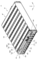
- FIG. 1 is a front perspective view of a battery module 1 according to an embodiment.
- FIG. 2 is a diagram from FIG. 1 with the container 20 removed.
- the X direction indicates the front-rear direction of the battery module 1.
- the tip side of the arrow indicating the X direction will be the rear side of the battery module 1.
- the base end side of the arrow indicating the X direction will be the front side of the battery module 1.
- the Y direction is perpendicular to the X direction.
- the Y direction indicates the left and right direction of the battery module 1.
- the tip side of the arrow indicating the Y direction will be the left side of the battery module 1.
- the base end side of the arrow indicating the Y direction will be the right side of the battery module 1.
- the Z direction is perpendicular to both the X direction and the Y direction.
- the Z direction indicates the vertical direction of the battery module 1.
- the tip side of the arrow indicating the Z direction is assumed to be the upper side of the battery module 1.
- the base end side of the arrow indicating the Z direction will be referred to as the lower side of the battery module 1.
- the relationships between the X direction, Y direction, and Z direction and the front-rear direction, left-right direction, and up-down direction of the battery module 1 are not limited to the above-mentioned example. These relationships differ depending on the actual arrangement of battery module 1.
- the battery module 1 includes a cell stack 10, a housing 20, a front voltage detection device 30, and a rear voltage detection device 30'.
- the cell stack 10 includes a plurality of cell groups 100G. Each cell group 100G includes a plurality of battery cells 100.
- the container 20 includes a front cover 210, a rear cover 220, a right cover 230, a left cover 240, a lower cover 250, and an upper cover 260.
- the front voltage detection device 30 includes a holder 310, a plurality of voltage detection lines 320, two sockets 330, and a terminal 340.
- a plurality of voltage detection tip portions 322 are provided at one end of the plurality of voltage detection lines 320 on the tab group 110 side, which will be described later.
- the plurality of battery cells 100 are stacked in the Y direction. When viewed from the Y direction, each battery cell 100 has a substantially rectangular shape.
- the longitudinal direction of each battery cell 100 is approximately parallel to the X direction.
- the lateral direction of each battery cell 100 is approximately parallel to the Z direction.
- the thickness direction of each battery cell 100 is approximately parallel to the Y direction.
- the structure of each battery cell 100 is not limited to this example.
- Each battery cell 100 has a battery element (not shown), an exterior material 102, a positive electrode tab 112, and a negative electrode tab 114.
- the exterior material 102 seals a battery element and an electrolytic solution (not shown).
- the battery element includes a plurality of positive electrodes (not shown) and a plurality of negative electrodes (not shown) alternately stacked in the Y direction, and a separator (not shown) located between the positive electrodes and negative electrodes adjacent to each other in the Y direction.
- the positive electrode tab 112 and the negative electrode tab 114 are pulled out from opposite sides of the exterior material 102 in the X direction.
- the positive electrode tab 112 is electrically connected to the plurality of positive electrodes described above.
- the positive electrode tab 112 is made of aluminum, for example.
- the negative electrode tab 114 is electrically connected to the plurality of negative electrodes described above.
- the negative electrode tab 114 is made of copper, for example.
- Each cell group 100G includes two battery cells 100 connected in parallel.
- the positive electrode tabs 112 pulled out from the two battery cells 100 included in each cell group 100G are oriented toward the same side in the X direction.
- the negative electrode tabs 114 pulled out from the two battery cells 100 included in each cell group 100G are oriented toward the same side in the X direction.
- the plurality of cell groups 100G are connected in series.
- Cell groups 100G adjacent to each other in the Y direction have a tab group 110 located in front or behind the cell group 100G.
- the tab group 110 includes two positive electrode tabs 112 pulled out from one side of the cell group 100G adjacent in the Y direction, and two negative electrode tabs 114 pulled out from the other side of the cell group 100G adjacent in the Y direction. There is.
- the two positive electrode tabs 112 and the two negative electrode tabs 114 are joined to each other by, for example, laser welding.
- the plurality of tab groups 110 located at the front of the cell stack 10 and the plurality of tab groups 110 located at the rear of the cell stack 10 are alternated in the Y direction.
- the cell group 100G located on the leftmost side and the cell group 100G located second from the left have the tab group 110 located in front of these cell groups 100G. There is. Further, the cell group 100G located second from the left and the cell group 100G located third from the left have a tab group 110 located behind these cell groups 100G.
- each cell group 100G may include three or more battery cells 100. Further, a plurality of single battery cells 100 may be connected in series.
- the container 20 includes a cell stack 10, a front voltage detection device 30, and a rear voltage detection device 30'.
- the front cover 210 covers the front of the cell stack 10 and the front voltage detection device 30.
- the rear cover 220 covers the rear of the cell stack 10 and the rear voltage detection device 30'.
- the right cover 230 covers the right side of the cell stack 10.
- the left cover 240 covers the left side of the cell stack 10.
- the lower cover 250 covers the lower part of the cell stack 10.
- the upper cover 260 covers the top of the cell stack 10.
- the holder 310 is provided in front of the cell stack 10.
- Holder 310 is made of resin, for example.
- the holder 310 integrally holds a plurality of voltage detection lines 320, a plurality of voltage detection tips 322, and two sockets 330. Therefore, by positioning the holder 310 with respect to the cell stack 10, the plurality of voltage detection lines 320 and the plurality of voltage detection tips 322 can be positioned. For example, by attaching the holder 310 to the container 20, the holder 310 is positioned with respect to the cell stack 10. When the holder 310 is positioned, each of the plurality of voltage detection tips 322 is located in front of each of the plurality of tab groups 110 located in front of the cell stack 10.
- the plurality of voltage detection lines 320 are, for example, wire harnesses. Each of the plurality of voltage detection lines 320 electrically connects each of the plurality of tab groups 110 and the socket 330. Specifically, one end of each of the plurality of voltage detection lines 320 is electrically connected to each of the plurality of tab groups 110 located in front of the cell stack 10 via each of the plurality of voltage detection tips 322. It is connected. Each voltage detection tip 322 is, for example, a conductive plate such as a metal plate. Each voltage detection tip 322 is joined to the front surface of each tab group 110 by, for example, laser welding. The other end of each of the plurality of voltage detection lines 320 is electrically connected to a socket 330.
- the terminal 340 is electrically connected to the positive electrode tab 112 pulled out forward from the rightmost battery cell 100.
- the cell stack 10 can be electrically connected to external equipment via the terminal 340.
- the rear voltage detection device 30' includes a holder (not shown), a plurality of voltage detection wires, a connector, and a terminal.
- a terminal of the rear voltage detection device 30' is electrically connected to a negative electrode tab 114 pulled out rearward from the battery cell 100 located on the leftmost side.
- FIG. 3 is an enlarged perspective view of a portion of the front voltage detection device 30 according to the embodiment.
- FIG. 4 is a diagram from FIG. 3 with two sockets 330 and plug 430 removed.
- FIG. 5 is a rear perspective view of the socket 330 according to the embodiment.
- the two sockets 330 and plug 430 will be described with reference to FIG. 3.
- a step 262 is provided at the front end of the upper cover 260. Due to the step 262, the front end of the upper cover 260 is located at a lower position in the Z direction than the rear part of the front end of the upper cover 260.
- the two sockets 330 shown in FIG. 3 are placed in the space formed by the step 262. Therefore, the volumetric efficiency of the battery module 1 can be improved.
- the plug 430 shown in FIG. 3 can be connected to the socket 330 on the left side shown in FIG.
- the plug 430 has a plurality of terminals and a plug cover 434 (not shown).
- the plurality of terminals of the plug 430 protrude toward the right.
- the plug cover 434 surrounds the plurality of terminals of the plug 430. Therefore, compared to the case where the plurality of terminals of the plug 430 are not surrounded by the plug cover 434, it is possible to make it difficult for foreign objects such as an operator's fingers or dust to come into contact with the plurality of terminals of the plug 430.
- the socket 330 on the left side shown in FIG. 3 has a body 332 and a socket cover 334. Some of the voltage detection lines 320 among the plurality of voltage detection lines 320 are electrically connected to the socket 330 on the left side shown in FIG. 3 . In the example shown in FIG. 3, some of the voltage detection lines 320 are connected to the socket 330 by passing through a tube 324 attached to the socket 330.
- the body 332 is provided with a plurality of terminal holes 332a. Terminals are embedded inside the plurality of terminal holes 332a. Therefore, in the socket 330 according to the embodiment, compared to a case where the terminal of the socket 330 protrudes to the outside, the terminal can be made less likely to come into contact with foreign objects such as a worker's finger or dust.
- Each of the plurality of terminals of the plug 430 is inserted into each of the plurality of terminal holes 332a in the Y direction. By inserting the plurality of terminals of the plug 430 into each of the plurality of terminal holes 332a in the Y direction, the socket 330 and the plug 430 are electrically connected.
- the socket cover 334 surrounds at least a portion of the body 332 with a gap 336 in between.
- the socket 330 and the plug 430 are connected to each other. Therefore, compared to the case where the gap 336 and the plug cover 434 are not provided, the mechanical connection between the socket 330 and the plug 430 can be made stronger.
- the gap 336 and the plug cover 434 may not be provided.
- the socket 330 and the plug 430 can be mechanically connected to each other by inserting each of the plurality of terminals of the plug 430 into each of the plurality of terminal holes 332a in the Y direction.
- the socket 330 on the right side shown in FIG. 3 has a similar configuration to the socket 330 on the left side shown in FIG.
- some voltage detection lines 320 are electrically connected to one socket 330
- other voltage detection lines 320 are electrically connected to the other socket 330. be able to. Therefore, the number of terminal holes 332a of each socket 330 can be reduced compared to the case where all the plurality of voltage detection lines 320 are electrically connected to a single socket 330.
- the terminal holes 332a of each socket 330 are arranged in the Z direction, the width of each socket 330 in the Z direction can be reduced. Therefore, the top surface of each socket 330 can be prevented from protruding above the top surface of the upper cover 260.
- the front voltage detection device 30 may have only one socket 330, or may have three or more sockets 330.
- the socket 330 on the right side shown in FIG. 3 is located more forward than the socket 330 on the left side shown in FIG. That is, the two sockets 330 shown in FIG. 3 are offset from each other in the X direction. Therefore, a space can be secured behind the left socket 330 shown in FIG. 3 for passing the plurality of voltage detection lines 320 connected to the right socket 330 shown in FIG. Therefore, compared to the case where the two sockets 330 shown in FIG. 3 are aligned in the X direction, the space in the Y direction for arranging the two sockets 330 shown in FIG. 3 can be made smaller.
- the layout of the socket 330 is not limited to this example.
- the two sockets 330 shown in FIG. 3 may be aligned in the X direction.
- FIGS. 4 and 5 A method for attaching the left socket 330 shown in FIG. 3 to the holder 310 will be described using FIGS. 4 and 5.
- a pair of locking grooves 352 are provided on the front surface of the holder 310.
- the pair of locking grooves 352 extend substantially parallel to the Y direction.
- a pair of locking portions 354 are provided on the rear surface of the socket cover 334.
- the pair of locking portions 354 extend substantially parallel to the Y direction.
- the pair of locking portions 354 can be inserted into the pair of locking grooves 352 from the left side of the pair of locking grooves 352 in the Y direction.
- the socket 330 is attached to the holder 310 by inserting the pair of locking portions 354 into the pair of locking grooves 352 from the left side of the pair of locking grooves 352 in the Y direction.
- the pair of locking grooves 352 and the pair of locking portions 354 form a mounting structure for attaching the holder 310 and the socket 330 on the left side shown in FIG. 3 to each other.
- the mounting structure is not limited to the example of the pair of locking grooves 352 and the pair of locking portions 354.
- the socket 330 on the right side shown in FIG. 3 is also attached to the holder 310 using the same mounting structure as the socket 330 on the left side shown in FIG.
- the above-described mounting structure that is, the pair of locking grooves 352 and the pair of locking portions 354 are located on the rear side of the socket 330. Therefore, when the plug cover 434 is inserted into the gap 336 in the Y direction, the mounting structure does not interfere with the plug cover 434. Therefore, there is no need to provide a notch in the plug cover 434 to avoid interference with the mounting structure. Therefore, a decrease in the strength of the plug cover 434 due to the notch can be suppressed. However, if necessary, the plug cover 434 may be provided with a notch.
- a socket 330 is provided on the holder 310. Therefore, after the front voltage detection device 30 is attached to the cell stack 10, the cell stack 10 and the front voltage detection device 30 can be housed in the container 20.
- the socket 330 is provided in the container 20
- the socket 330 is attached to the container 20 after the cell stack 10 is accommodated in the container 20.
- an extra length of the plurality of voltage detection lines 320 is required to draw the plurality of voltage detection lines 320 to the outside of the container 20.
- the socket 330 is a connector provided on the front voltage detection device 30, and the plug 430 is an external connector of the front voltage detection device 30.
- the connector provided on the front voltage detection device 30 may be a plug
- the external connector of the front voltage detection device 30 may be a socket.
- the workability for assembling the battery module 1 can be improved compared to the case where the above-mentioned plug is provided in the container 20.
- FIG. 6 is an enlarged perspective view of the front portion of the front voltage detection device 30A according to Modification 1.
- the front voltage detection device 30A according to Modification 1 is the same as the front voltage detection device 30 according to the embodiment except for the following points.
- At least a portion of the socket 330A is embedded in a recess 312A provided on the upper surface of the holder 310A.
- a gap 336A is provided between the outer surface of the socket 330A and the inner surface of the recess 312A.
- the plug 430A can be connected to the socket 330A from above the socket 330A. By inserting the plug cover 434A into the gap 336A in the Z direction, the socket 330A and the plug 430A are mechanically connected to each other. Therefore, in the first modification as well, it is possible to strengthen the mechanical connection between the socket 330A and the plug 430A, similarly to the embodiment.
- FIG. 7 is an enlarged perspective view of the front portion of the front voltage detection device 30B according to Modification 2.
- the front voltage detection device 30B according to the second modification is the same as the front voltage detection device 30 according to the embodiment except for the following points.
- At least a portion of the socket 330B is embedded in a recess 312B provided on the front surface of the holder 310B.
- a gap 336B is provided between the outer surface of the socket 330B and the inner surface of the recess 312B.
- Plug 430B can be connected to socket 330B from the front of socket 330B. By inserting the plug cover 434B into the gap 336B in the X direction, the socket 330B and the plug 430B are mechanically connected to each other. Therefore, in the second modification as well, the mechanical connection between the socket 330B and the plug 430B can be strengthened similarly to the embodiment.
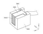
- FIG. 8 is an enlarged perspective view of a portion of a front voltage detection device 30C according to Modification 3.
- a forward voltage detection device 30C according to Modification 3 is the same as the front voltage detection device 30 according to the embodiment except for the following points.
- a front voltage detection device 30C according to modification 3 includes a socket holder 350C.
- the socket holder 350C is attached to a holder 310 (not shown).
- Socket holder 350C holds socket 330C.
- a plurality of terminal holes 332aC are provided on the left side surface of the socket 330C.
- the socket holder 350C holds the socket 330C with a gap 336C formed between the socket 330C and a portion of the socket holder 350C surrounding the socket 330C.
- the socket 330C and the unillustrated plug 430 are mechanically connected to each other by inserting the unillustrated plug cover 434 into the gap 336C in the Y direction.
Landscapes
- Chemical & Material Sciences (AREA)
- Chemical Kinetics & Catalysis (AREA)
- Electrochemistry (AREA)
- General Chemical & Material Sciences (AREA)
- Connection Of Batteries Or Terminals (AREA)
- Battery Mounting, Suspending (AREA)
- Measurement Of Current Or Voltage (AREA)
Abstract
A front voltage detection device (30) comprises: a holder (310); a plurality of voltage detection lines (320); and a socket (330). The plurality of voltage detection lines (320) are electrically connected to a plurality of battery cells (100). The plurality of voltage detection lines (320) are held in the holder (310). The socket (330) is electrically connected to the plurality of voltage detection lines (320). The socket (330) is provided in the holder (310).
Description
本発明は、電圧検出装置及び電池モジュールに関する。
The present invention relates to a voltage detection device and a battery module.
例えば特許文献1に記載されているように、電池モジュールは、複数の電池セル、ハウジング、ワイヤハーネス及びコネクタを備えている。ハウジングは、複数の電池セルを収容している。コネクタは、ワイヤハーネスを介して複数の電池セルに電気的に接続されている。特許文献1に記載の電圧検出装置では、コネクタがハウジングに取り付けられている。
For example, as described in Patent Document 1, a battery module includes a plurality of battery cells, a housing, a wire harness, and a connector. The housing accommodates a plurality of battery cells. The connector is electrically connected to the plurality of battery cells via a wire harness. In the voltage detection device described in Patent Document 1, the connector is attached to the housing.
例えば特許文献1に記載されているように、コネクタがハウジングに取り付けられている場合、複数の電池セル及びワイヤハーネスをハウジングに収容した後にコネクタが収容体に取り付けられる。しかしながら、この場合、例えば、ワイヤハーネスをハウジングの外側まで引き出すためのワイヤハーネスの余長が必要になる等して、電池モジュールを組み立てるための作業性が低下することがある。
For example, as described in Patent Document 1, when the connector is attached to the housing, the connector is attached to the housing after a plurality of battery cells and wire harnesses are housed in the housing. However, in this case, for example, an extra length of the wire harness is required to pull the wire harness out to the outside of the housing, which may reduce the workability for assembling the battery module.
本発明の目的の一例は、電池モジュールを組み立てるための作業性を向上させることにある。本発明の他の目的は、本明細書の記載から明らかになるであろう。
An example of the object of the present invention is to improve workability for assembling battery modules. Other objects of the invention will become apparent from the description herein.
本発明の一態様は、以下のとおりである。
[1]
保持体と、
複数の電池セルに電気的に接続され、前記保持体に保持された複数の電圧検出線と、
前記複数の電圧検出線に電気的に接続され、前記保持体に設けられたコネクタと、
を備える電圧検出装置。
[2]
外部端子の少なくとも一部分が挿通される端子孔が前記コネクタに設けられている、[1]に記載の電圧検出装置。
[3]
前記コネクタに接続される外部コネクタの少なくとも一部分が挿通される隙間が設けられている、[1]又は[2]に記載の電圧検出装置。
[4]
前記保持体と前記コネクタとを互いに取り付ける取付構造をさらに備える、[1]~[3]のいずれか一つに記載の電圧検出装置。
[5]
保持体と、
複数の電池セルに電気的に接続され、前記保持体に保持された複数の電圧検出線と、
前記複数の電圧検出線に電気的に接続されたソケットと、
を備え、
前記ソケットの少なくとも一部分が、前記保持体に設けられた凹部に埋め込まれている、電圧検出装置。
[6]
前記ソケットと前記凹部との間に隙間が設けられている、[5]に記載の電圧検出装置。
[7]
前記複数の電池セルが所定の第1方向に積層されており、
前記保持体が、前記複数の電池セルにおける前記第1方向に直交する第2方向側に位置し、
前記凹部が、前記保持体における前記第1方向及び前記第2方向に直交する第3方向側の面に設けられている、[5]又は[6]に記載の電圧検出装置。
[8]
前記複数の電池セルと、
[1]~「7」のいずれか一つに記載の電圧検出装置と、
を備える電池モジュール。 One aspect of the present invention is as follows.
[1]
a holding body;
a plurality of voltage detection lines electrically connected to a plurality of battery cells and held by the holder;
a connector electrically connected to the plurality of voltage detection lines and provided on the holder;
A voltage detection device comprising:
[2]
The voltage detection device according to [1], wherein the connector is provided with a terminal hole through which at least a portion of an external terminal is inserted.
[3]
The voltage detection device according to [1] or [2], wherein a gap is provided through which at least a portion of an external connector connected to the connector is inserted.
[4]
The voltage detection device according to any one of [1] to [3], further comprising a mounting structure for mounting the holding body and the connector to each other.
[5]
a holding body;
a plurality of voltage detection lines electrically connected to a plurality of battery cells and held by the holder;
a socket electrically connected to the plurality of voltage detection lines;
Equipped with
A voltage detection device, wherein at least a portion of the socket is embedded in a recess provided in the holder.
[6]
The voltage detection device according to [5], wherein a gap is provided between the socket and the recess.
[7]
The plurality of battery cells are stacked in a predetermined first direction,
The holding body is located on a second direction side perpendicular to the first direction in the plurality of battery cells,
The voltage detection device according to [5] or [6], wherein the recess is provided on a surface of the holding body on a third direction side perpendicular to the first direction and the second direction.
[8]
the plurality of battery cells;
[1] The voltage detection device according to any one of "7",
A battery module comprising:
[1]
保持体と、
複数の電池セルに電気的に接続され、前記保持体に保持された複数の電圧検出線と、
前記複数の電圧検出線に電気的に接続され、前記保持体に設けられたコネクタと、
を備える電圧検出装置。
[2]
外部端子の少なくとも一部分が挿通される端子孔が前記コネクタに設けられている、[1]に記載の電圧検出装置。
[3]
前記コネクタに接続される外部コネクタの少なくとも一部分が挿通される隙間が設けられている、[1]又は[2]に記載の電圧検出装置。
[4]
前記保持体と前記コネクタとを互いに取り付ける取付構造をさらに備える、[1]~[3]のいずれか一つに記載の電圧検出装置。
[5]
保持体と、
複数の電池セルに電気的に接続され、前記保持体に保持された複数の電圧検出線と、
前記複数の電圧検出線に電気的に接続されたソケットと、
を備え、
前記ソケットの少なくとも一部分が、前記保持体に設けられた凹部に埋め込まれている、電圧検出装置。
[6]
前記ソケットと前記凹部との間に隙間が設けられている、[5]に記載の電圧検出装置。
[7]
前記複数の電池セルが所定の第1方向に積層されており、
前記保持体が、前記複数の電池セルにおける前記第1方向に直交する第2方向側に位置し、
前記凹部が、前記保持体における前記第1方向及び前記第2方向に直交する第3方向側の面に設けられている、[5]又は[6]に記載の電圧検出装置。
[8]
前記複数の電池セルと、
[1]~「7」のいずれか一つに記載の電圧検出装置と、
を備える電池モジュール。 One aspect of the present invention is as follows.
[1]
a holding body;
a plurality of voltage detection lines electrically connected to a plurality of battery cells and held by the holder;
a connector electrically connected to the plurality of voltage detection lines and provided on the holder;
A voltage detection device comprising:
[2]
The voltage detection device according to [1], wherein the connector is provided with a terminal hole through which at least a portion of an external terminal is inserted.
[3]
The voltage detection device according to [1] or [2], wherein a gap is provided through which at least a portion of an external connector connected to the connector is inserted.
[4]
The voltage detection device according to any one of [1] to [3], further comprising a mounting structure for mounting the holding body and the connector to each other.
[5]
a holding body;
a plurality of voltage detection lines electrically connected to a plurality of battery cells and held by the holder;
a socket electrically connected to the plurality of voltage detection lines;
Equipped with
A voltage detection device, wherein at least a portion of the socket is embedded in a recess provided in the holder.
[6]
The voltage detection device according to [5], wherein a gap is provided between the socket and the recess.
[7]
The plurality of battery cells are stacked in a predetermined first direction,
The holding body is located on a second direction side perpendicular to the first direction in the plurality of battery cells,
The voltage detection device according to [5] or [6], wherein the recess is provided on a surface of the holding body on a third direction side perpendicular to the first direction and the second direction.
[8]
the plurality of battery cells;
[1] The voltage detection device according to any one of "7",
A battery module comprising:
本発明の上記態様によれば、電池モジュールを組み立てるための作業性を向上させることができる。
According to the above aspect of the present invention, workability for assembling battery modules can be improved.
以下、本発明の実施形態について、図面を用いて説明する。すべての図面において、同様な構成要素には同様の符号を付し、適宜説明を省略する。
Hereinafter, embodiments of the present invention will be described using the drawings. In all the drawings, similar components are denoted by the same reference numerals, and description thereof will be omitted as appropriate.
図1は、実施形態に係る電池モジュール1の前方斜視図である。図2は、図1から収容体20を取り除いた図である。
FIG. 1 is a front perspective view of a battery module 1 according to an embodiment. FIG. 2 is a diagram from FIG. 1 with the container 20 removed.
各図では、説明のため、X方向、Y方向及びZ方向を示す矢印が示されている。X方向は、電池モジュール1の前後方向を示している。以下、特に断りがない限り、X方向を示す矢印の先端側を電池モジュール1の後側とする。以下、特に断りがない限り、X方向を示す矢印の基端側を電池モジュール1の前側とする。Y方向は、X方向に直交している。Y方向は、電池モジュール1の左右方向を示している。以下、特に断りがない限り、Y方向を示す矢印の先端側を電池モジュール1の左側とする。以下、特に断りがない限り、Y方向を示す矢印の基端側を電池モジュール1の右側とする。Z方向は、X方向及びY方向の双方に直交している。Z方向は、電池モジュール1の上下方向を示している。以下、特に断りがない限り、Z方向を示す矢印の先端側を電池モジュール1の上側とする。以下、特に断りがない限り、Z方向を示す矢印の基端側を電池モジュール1の下側とする。ただし、X方向、Y方向及びZ方向と、電池モジュール1の前後方向、左右方向及び上下方向との関係は上述した例に限定されない。これらの関係は、電池モジュール1の実際の配置に応じて異なる。
In each figure, arrows indicating the X direction, Y direction, and Z direction are shown for explanation. The X direction indicates the front-rear direction of the battery module 1. Hereinafter, unless otherwise specified, the tip side of the arrow indicating the X direction will be the rear side of the battery module 1. Hereinafter, unless otherwise specified, the base end side of the arrow indicating the X direction will be the front side of the battery module 1. The Y direction is perpendicular to the X direction. The Y direction indicates the left and right direction of the battery module 1. Hereinafter, unless otherwise specified, the tip side of the arrow indicating the Y direction will be the left side of the battery module 1. Hereinafter, unless otherwise specified, the base end side of the arrow indicating the Y direction will be the right side of the battery module 1. The Z direction is perpendicular to both the X direction and the Y direction. The Z direction indicates the vertical direction of the battery module 1. Hereinafter, unless otherwise specified, the tip side of the arrow indicating the Z direction is assumed to be the upper side of the battery module 1. Hereinafter, unless otherwise specified, the base end side of the arrow indicating the Z direction will be referred to as the lower side of the battery module 1. However, the relationships between the X direction, Y direction, and Z direction and the front-rear direction, left-right direction, and up-down direction of the battery module 1 are not limited to the above-mentioned example. These relationships differ depending on the actual arrangement of battery module 1.
電池モジュール1は、セル積層体10、収容体20、前方電圧検出装置30及び後方電圧検出装置30´を備えている。セル積層体10は、複数のセル群100Gを有している。各セル群100Gは、複数の電池セル100を含んでいる。収容体20は、前方カバー210、後方カバー220、右方カバー230、左方カバー240、下方カバー250及び上方カバー260を有している。前方電圧検出装置30は、保持体310、複数の電圧検出線320、2つのソケット330及びターミナル340を有している。複数の電圧検出線320の後述するタブ群110側の一端には、複数の電圧検出先端部322が設けられている。
The battery module 1 includes a cell stack 10, a housing 20, a front voltage detection device 30, and a rear voltage detection device 30'. The cell stack 10 includes a plurality of cell groups 100G. Each cell group 100G includes a plurality of battery cells 100. The container 20 includes a front cover 210, a rear cover 220, a right cover 230, a left cover 240, a lower cover 250, and an upper cover 260. The front voltage detection device 30 includes a holder 310, a plurality of voltage detection lines 320, two sockets 330, and a terminal 340. A plurality of voltage detection tip portions 322 are provided at one end of the plurality of voltage detection lines 320 on the tab group 110 side, which will be described later.
複数の電池セル100は、Y方向に積層されている。Y方向から見て、各電池セル100は、略長方形形状となっている。各電池セル100の長手方向は、X方向に略平行となっている。各電池セル100の短手方向は、Z方向に略平行となっている。各電池セル100の厚み方向は、Y方向に略平行となっている。ただし、各電池セル100の構造は、この例に限定されない。
The plurality of battery cells 100 are stacked in the Y direction. When viewed from the Y direction, each battery cell 100 has a substantially rectangular shape. The longitudinal direction of each battery cell 100 is approximately parallel to the X direction. The lateral direction of each battery cell 100 is approximately parallel to the Z direction. The thickness direction of each battery cell 100 is approximately parallel to the Y direction. However, the structure of each battery cell 100 is not limited to this example.
各電池セル100は、不図示の電池要素、外装材102、正極タブ112及び負極タブ114を有している。外装材102は、電池要素及び不図示の電解液を封止している。電池要素は、Y方向に交互に積層された不図示の複数の正極及び複数の負極と、Y方向に隣り合う正極及び負極の間に位置する不図示のセパレータと、を含んでいる。正極タブ112及び負極タブ114は、外装材102のX方向の互いに反対側の辺から引き出されている。正極タブ112は、上述の複数の正極に電気的に接続されている。正極タブ112は、例えば、アルミニウムからなっている。負極タブ114は、上述の複数の負極に電気的に接続されている。負極タブ114は、例えば、銅からなっている。
Each battery cell 100 has a battery element (not shown), an exterior material 102, a positive electrode tab 112, and a negative electrode tab 114. The exterior material 102 seals a battery element and an electrolytic solution (not shown). The battery element includes a plurality of positive electrodes (not shown) and a plurality of negative electrodes (not shown) alternately stacked in the Y direction, and a separator (not shown) located between the positive electrodes and negative electrodes adjacent to each other in the Y direction. The positive electrode tab 112 and the negative electrode tab 114 are pulled out from opposite sides of the exterior material 102 in the X direction. The positive electrode tab 112 is electrically connected to the plurality of positive electrodes described above. The positive electrode tab 112 is made of aluminum, for example. The negative electrode tab 114 is electrically connected to the plurality of negative electrodes described above. The negative electrode tab 114 is made of copper, for example.
各セル群100Gは、並列に接続された2つの電池セル100を含んでいる。各セル群100Gに含まれる2つの電池セル100から引き出された正極タブ112はX方向の同じ側に向けられている。各セル群100Gに含まれる2つの電池セル100から引き出された負極タブ114はX方向の同じ側に向けられている。Y方向に隣り合うセル群100Gの一方から引き出された正極タブ112及び負極タブ114と、Y方向に隣り合うセル群100Gの他方から引き出された正極タブ112及び負極タブ114と、はX方向において互いに反対側に向けられている。
Each cell group 100G includes two battery cells 100 connected in parallel. The positive electrode tabs 112 pulled out from the two battery cells 100 included in each cell group 100G are oriented toward the same side in the X direction. The negative electrode tabs 114 pulled out from the two battery cells 100 included in each cell group 100G are oriented toward the same side in the X direction. The positive electrode tab 112 and the negative electrode tab 114 pulled out from one side of the cell group 100G adjacent in the Y direction, and the positive electrode tab 112 and the negative electrode tab 114 pulled out from the other side of the cell group 100G adjacent in the Y direction, in the X direction. facing away from each other.
複数のセル群100Gは、直列に接続されている。Y方向に隣り合うセル群100Gは、当該セル群100Gの前方又は後方に位置するタブ群110を有している。タブ群110は、Y方向に隣り合うセル群100Gの一方から引き出された2つの正極タブ112と、Y方向に隣り合うセル群100Gの他方から引き出された2つの負極タブ114と、を含んでいる。タブ群110において、当該2つの正極タブ112及び当該2つの負極タブ114は、例えばレーザ溶接によって互いに接合されている。セル積層体10の前方に位置する複数のタブ群110と、セル積層体10の後方に位置する複数のタブ群110と、はY方向において互い違いになっている。したがって、例えば図2に示す例において、最も左側に位置するセル群100Gと、左から2番目に位置するセル群100Gと、はこれらのセル群100Gの前方に位置するタブ群110を有している。また、左から2番目に位置するセル群100Gと、左から3番目に位置するセル群100Gと、はこれらのセル群100Gの後方に位置するタブ群110を有している。
The plurality of cell groups 100G are connected in series. Cell groups 100G adjacent to each other in the Y direction have a tab group 110 located in front or behind the cell group 100G. The tab group 110 includes two positive electrode tabs 112 pulled out from one side of the cell group 100G adjacent in the Y direction, and two negative electrode tabs 114 pulled out from the other side of the cell group 100G adjacent in the Y direction. There is. In the tab group 110, the two positive electrode tabs 112 and the two negative electrode tabs 114 are joined to each other by, for example, laser welding. The plurality of tab groups 110 located at the front of the cell stack 10 and the plurality of tab groups 110 located at the rear of the cell stack 10 are alternated in the Y direction. Therefore, for example, in the example shown in FIG. 2, the cell group 100G located on the leftmost side and the cell group 100G located second from the left have the tab group 110 located in front of these cell groups 100G. There is. Further, the cell group 100G located second from the left and the cell group 100G located third from the left have a tab group 110 located behind these cell groups 100G.
なお、セル積層体10の構造は、上述した例に限定されない。例えば、各セル群100Gは、3つ以上の電池セル100を含んでいてもよい。また、複数の単一の電池セル100が直列に接続されていてもよい。
Note that the structure of the cell stack 10 is not limited to the example described above. For example, each cell group 100G may include three or more battery cells 100. Further, a plurality of single battery cells 100 may be connected in series.
収容体20は、セル積層体10、前方電圧検出装置30及び後方電圧検出装置30´を備えている。前方カバー210は、セル積層体10及び前方電圧検出装置30の前方を覆っている。後方カバー220は、セル積層体10及び後方電圧検出装置30´の後方を覆っている。右方カバー230は、セル積層体10の右方を覆っている。左方カバー240は、セル積層体10の左方を覆っている。下方カバー250は、セル積層体10の下方を覆っている。上方カバー260は、セル積層体10の上方を覆っている。
The container 20 includes a cell stack 10, a front voltage detection device 30, and a rear voltage detection device 30'. The front cover 210 covers the front of the cell stack 10 and the front voltage detection device 30. The rear cover 220 covers the rear of the cell stack 10 and the rear voltage detection device 30'. The right cover 230 covers the right side of the cell stack 10. The left cover 240 covers the left side of the cell stack 10. The lower cover 250 covers the lower part of the cell stack 10. The upper cover 260 covers the top of the cell stack 10.
保持体310は、セル積層体10の前方に設けられている。保持体310は、例えば樹脂によって形成されている。保持体310は、複数の電圧検出線320、複数の電圧検出先端部322及び2つのソケット330を一体的に保持している。したがって、保持体310をセル積層体10に対して位置決めすることで、複数の電圧検出線320及び複数の電圧検出先端部322を位置決めすることができる。例えば、保持体310を収容体20に取り付けることで、保持体310はセル積層体10に対して位置決めされる。保持体310が位置決めされている場合、複数の電圧検出先端部322の各々は、セル積層体10の前方に位置する複数のタブ群110の各々の前方に位置している。
The holder 310 is provided in front of the cell stack 10. Holder 310 is made of resin, for example. The holder 310 integrally holds a plurality of voltage detection lines 320, a plurality of voltage detection tips 322, and two sockets 330. Therefore, by positioning the holder 310 with respect to the cell stack 10, the plurality of voltage detection lines 320 and the plurality of voltage detection tips 322 can be positioned. For example, by attaching the holder 310 to the container 20, the holder 310 is positioned with respect to the cell stack 10. When the holder 310 is positioned, each of the plurality of voltage detection tips 322 is located in front of each of the plurality of tab groups 110 located in front of the cell stack 10.
複数の電圧検出線320は、例えば、ワイヤハーネスである。複数の電圧検出線320の各々は、複数のタブ群110の各々とソケット330とを電気的に接続している。具体的には、複数の電圧検出線320の各々の一端は、複数の電圧検出先端部322の各々を介して、セル積層体10の前方に位置する複数のタブ群110の各々に電気的に接続されている。各電圧検出先端部322は、例えば金属板等の導体板である。各電圧検出先端部322は、例えばレーザ溶接によって各タブ群110の前面に接合されている。複数の電圧検出線320の各々の他端は、ソケット330に電気的に接続されている。
The plurality of voltage detection lines 320 are, for example, wire harnesses. Each of the plurality of voltage detection lines 320 electrically connects each of the plurality of tab groups 110 and the socket 330. Specifically, one end of each of the plurality of voltage detection lines 320 is electrically connected to each of the plurality of tab groups 110 located in front of the cell stack 10 via each of the plurality of voltage detection tips 322. It is connected. Each voltage detection tip 322 is, for example, a conductive plate such as a metal plate. Each voltage detection tip 322 is joined to the front surface of each tab group 110 by, for example, laser welding. The other end of each of the plurality of voltage detection lines 320 is electrically connected to a socket 330.
ターミナル340は、最も右側に配置された電池セル100から前方に引き出された正極タブ112に電気的に接続されている。セル積層体10は、ターミナル340を介して外部機器に電気的に接続可能になっている。
The terminal 340 is electrically connected to the positive electrode tab 112 pulled out forward from the rightmost battery cell 100. The cell stack 10 can be electrically connected to external equipment via the terminal 340.
後方電圧検出装置30´は、前方電圧検出装置30と同様にして、不図示の保持体、複数の電圧検出線、コネクタ及びターミナルを備えている。後方電圧検出装置30´のターミナルは、最も左側に配置された電池セル100から後方に引き出された負極タブ114に電気的に接続されている。
Similarly to the front voltage detection device 30, the rear voltage detection device 30' includes a holder (not shown), a plurality of voltage detection wires, a connector, and a terminal. A terminal of the rear voltage detection device 30' is electrically connected to a negative electrode tab 114 pulled out rearward from the battery cell 100 located on the leftmost side.
図3は、実施形態に係る前方電圧検出装置30の一部分の拡大斜視図である。図4は、図3から2つのソケット330及びプラグ430を取り除いた図である。図5は、実施形態に係るソケット330の後方斜視図である。
FIG. 3 is an enlarged perspective view of a portion of the front voltage detection device 30 according to the embodiment. FIG. 4 is a diagram from FIG. 3 with two sockets 330 and plug 430 removed. FIG. 5 is a rear perspective view of the socket 330 according to the embodiment.
図3を参照して、2つのソケット330及びプラグ430について説明する。
The two sockets 330 and plug 430 will be described with reference to FIG. 3.
図3に示すように、上方カバー260の前端には段差262が設けられている。段差262によって、上方カバー260の前端部は、上方カバー260の前端部の後方部よりも、Z方向において低い位置に位置している。図3に示す2つのソケット330は、段差262によって形成されるスペースに配置されている。このため、電池モジュール1の体積効率を向上させることができる。
As shown in FIG. 3, a step 262 is provided at the front end of the upper cover 260. Due to the step 262, the front end of the upper cover 260 is located at a lower position in the Z direction than the rear part of the front end of the upper cover 260. The two sockets 330 shown in FIG. 3 are placed in the space formed by the step 262. Therefore, the volumetric efficiency of the battery module 1 can be improved.
図3に示すプラグ430は、図3に示す左側のソケット330に接続可能になっている。プラグ430は、不図示の複数の端子及びプラグカバー434を有している。プラグ430の当該複数の端子は、右方に向けて突出している。プラグ430の右方から見て、プラグカバー434は、プラグ430の当該複数の端子を囲んでいる。したがって、プラグ430の当該複数の端子がプラグカバー434によって囲まれていない場合と比較して、作業者の指や埃等の異物がプラグ430の当該複数の端子に接触しにくくすることができる。
The plug 430 shown in FIG. 3 can be connected to the socket 330 on the left side shown in FIG. The plug 430 has a plurality of terminals and a plug cover 434 (not shown). The plurality of terminals of the plug 430 protrude toward the right. When viewed from the right side of the plug 430, the plug cover 434 surrounds the plurality of terminals of the plug 430. Therefore, compared to the case where the plurality of terminals of the plug 430 are not surrounded by the plug cover 434, it is possible to make it difficult for foreign objects such as an operator's fingers or dust to come into contact with the plurality of terminals of the plug 430.
図3に示す左側のソケット330は、ボディ332及びソケットカバー334を有している。図3に示す左側のソケット330には、複数の電圧検出線320のうちの一部の電圧検出線320が電気的に接続されている。図3に示す例において、当該一部の電圧検出線320は、ソケット330に取り付けられたチューブ324内を通過してソケット330に接続されている。
The socket 330 on the left side shown in FIG. 3 has a body 332 and a socket cover 334. Some of the voltage detection lines 320 among the plurality of voltage detection lines 320 are electrically connected to the socket 330 on the left side shown in FIG. 3 . In the example shown in FIG. 3, some of the voltage detection lines 320 are connected to the socket 330 by passing through a tube 324 attached to the socket 330.
ボディ332には、複数の端子孔332aが設けられている。複数の端子孔332aの内部には、端子が埋め込まれている。したがって、実施形態に係るソケット330では、ソケット330の端子が外部に突出している場合と比較して、作業者の指や埃等の異物に当該端子が接触しにくくすることができる。複数の端子孔332aの各々には、プラグ430の上述の複数の端子の各々がY方向に挿通される。プラグ430の当該複数の端子を複数の端子孔332aの各々にY方向に挿通することで、ソケット330及びプラグ430は電気的に接続される。
The body 332 is provided with a plurality of terminal holes 332a. Terminals are embedded inside the plurality of terminal holes 332a. Therefore, in the socket 330 according to the embodiment, compared to a case where the terminal of the socket 330 protrudes to the outside, the terminal can be made less likely to come into contact with foreign objects such as a worker's finger or dust. Each of the plurality of terminals of the plug 430 is inserted into each of the plurality of terminal holes 332a in the Y direction. By inserting the plurality of terminals of the plug 430 into each of the plurality of terminal holes 332a in the Y direction, the socket 330 and the plug 430 are electrically connected.
ソケットカバー334は、隙間336を介してボディ332の少なくとも一部分を囲んでいる。プラグカバー434の少なくとも一部分を隙間336にY方向に挿通することで、ソケット330及びプラグ430は互いに接続される。したがって、隙間336及びプラグカバー434が設けられていない場合と比較して、ソケット330及びプラグ430の機械的接続を強固にすることができる。ただし、隙間336及びプラグカバー434は設けられていなくてもよい。この場合においても、プラグ430の上述の複数の端子の各々を複数の端子孔332aの各々にY方向に挿通することで、ソケット330及びプラグ430を互いに機械的に接続することができる。
The socket cover 334 surrounds at least a portion of the body 332 with a gap 336 in between. By inserting at least a portion of the plug cover 434 into the gap 336 in the Y direction, the socket 330 and the plug 430 are connected to each other. Therefore, compared to the case where the gap 336 and the plug cover 434 are not provided, the mechanical connection between the socket 330 and the plug 430 can be made stronger. However, the gap 336 and the plug cover 434 may not be provided. Also in this case, the socket 330 and the plug 430 can be mechanically connected to each other by inserting each of the plurality of terminals of the plug 430 into each of the plurality of terminal holes 332a in the Y direction.
図3に示す右側のソケット330は、図3に示す左側のソケット330と同様の構成を有している。2つのソケット330が設けられている場合、一部の電圧検出線320を一方のソケット330に電気的に接続し、他の一部の電圧検出線320を他方のソケット330に電気的に接続することができる。このため、単一のソケット330にすべての複数の電圧検出線320が電気的に接続されている場合と比較して、各ソケット330の端子孔332aの数を少なくすることができる。例えば、各ソケット330の少なくとも一部の端子孔332aがZ方向に配列されている場合、各ソケット330のZ方向の幅を小さくすることができる。このため、各ソケット330の上面が上方カバー260の上面より上方に突出させなくすることができる。ただし、前方電圧検出装置30は、1つのみのソケット330を有していてもよいし、又は3つ以上のソケット330を有していてもよい。
The socket 330 on the right side shown in FIG. 3 has a similar configuration to the socket 330 on the left side shown in FIG. When two sockets 330 are provided, some voltage detection lines 320 are electrically connected to one socket 330, and other voltage detection lines 320 are electrically connected to the other socket 330. be able to. Therefore, the number of terminal holes 332a of each socket 330 can be reduced compared to the case where all the plurality of voltage detection lines 320 are electrically connected to a single socket 330. For example, if at least some of the terminal holes 332a of each socket 330 are arranged in the Z direction, the width of each socket 330 in the Z direction can be reduced. Therefore, the top surface of each socket 330 can be prevented from protruding above the top surface of the upper cover 260. However, the front voltage detection device 30 may have only one socket 330, or may have three or more sockets 330.
図3に示す右側のソケット330は、図3に示す左側のソケット330より前方に配置されている。すなわち、図3に示す2つのソケット330は、X方向において互いにずれている。したがって、図3に示す左側のソケット330の後方には、図3に示す右側のソケット330に接続される複数の電圧検出線320を通すための空間を確保することができる。したがって、図3に示す2つのソケット330をX方向において揃える場合と比較して、図3に示す2つのソケット330を配置するためのY方向のスペースを小さくすることができる。ただし、ソケット330のレイアウトはこの例に限定されない。例えば、図3に示す2つのソケット330は、X方向において揃っていてもよい。
The socket 330 on the right side shown in FIG. 3 is located more forward than the socket 330 on the left side shown in FIG. That is, the two sockets 330 shown in FIG. 3 are offset from each other in the X direction. Therefore, a space can be secured behind the left socket 330 shown in FIG. 3 for passing the plurality of voltage detection lines 320 connected to the right socket 330 shown in FIG. Therefore, compared to the case where the two sockets 330 shown in FIG. 3 are aligned in the X direction, the space in the Y direction for arranging the two sockets 330 shown in FIG. 3 can be made smaller. However, the layout of the socket 330 is not limited to this example. For example, the two sockets 330 shown in FIG. 3 may be aligned in the X direction.
図4及び図5を用いて、図3に示す左側のソケット330を保持体310に取り付ける方法について説明する。
A method for attaching the left socket 330 shown in FIG. 3 to the holder 310 will be described using FIGS. 4 and 5.
図4に示すように、保持体310の前面には、一対の係止溝352が設けられている。一対の係止溝352は、Y方向に略平行に延在している。図5に示すように、ソケットカバー334の後面には、一対の係止部354が設けられている。一対の係止部354は、Y方向に略平行に延在している。一対の係止部354は、一対の係止溝352の左方から一対の係止溝352にY方向に挿通可能になっている。一対の係止部354を一対の係止溝352の左方から一対の係止溝352にY方向に挿通することで、ソケット330が保持体310に取り付けられる。すなわち、一対の係止溝352及び一対の係止部354は、保持体310と、図3に示す左側のソケット330と、を互いに取り付ける取付構造となっている。ただし、当該取付構造は、一対の係止溝352及び一対の係止部354の例に限定されない。図3に示す右側のソケット330も、図3に示す左側のソケット330の取付構造と同様の取付構造によって保持体310に取り付けられている。
As shown in FIG. 4, a pair of locking grooves 352 are provided on the front surface of the holder 310. The pair of locking grooves 352 extend substantially parallel to the Y direction. As shown in FIG. 5, a pair of locking portions 354 are provided on the rear surface of the socket cover 334. The pair of locking portions 354 extend substantially parallel to the Y direction. The pair of locking portions 354 can be inserted into the pair of locking grooves 352 from the left side of the pair of locking grooves 352 in the Y direction. The socket 330 is attached to the holder 310 by inserting the pair of locking portions 354 into the pair of locking grooves 352 from the left side of the pair of locking grooves 352 in the Y direction. That is, the pair of locking grooves 352 and the pair of locking portions 354 form a mounting structure for attaching the holder 310 and the socket 330 on the left side shown in FIG. 3 to each other. However, the mounting structure is not limited to the example of the pair of locking grooves 352 and the pair of locking portions 354. The socket 330 on the right side shown in FIG. 3 is also attached to the holder 310 using the same mounting structure as the socket 330 on the left side shown in FIG.
上述のように、図4及び図5に示す例では、上述の取付構造、すなわち、一対の係止溝352及び一対の係止部354がソケット330の後面側に位置している。したがって、プラグカバー434を隙間336にY方向に挿通する場合において、当該取付構造がプラグカバー434に干渉しない。したがって、当該取付構造の干渉を回避するための切欠きをプラグカバー434に設ける必要がない。したがって、当該切欠きによるプラグカバー434の強度の低下を抑制することができる。ただし、必要に応じて、プラグカバー434には切欠きが設けられていてもよい。
As described above, in the example shown in FIGS. 4 and 5, the above-described mounting structure, that is, the pair of locking grooves 352 and the pair of locking portions 354 are located on the rear side of the socket 330. Therefore, when the plug cover 434 is inserted into the gap 336 in the Y direction, the mounting structure does not interfere with the plug cover 434. Therefore, there is no need to provide a notch in the plug cover 434 to avoid interference with the mounting structure. Therefore, a decrease in the strength of the plug cover 434 due to the notch can be suppressed. However, if necessary, the plug cover 434 may be provided with a notch.
実施形態では、ソケット330が保持体310に設けられている。したがって、前方電圧検出装置30をセル積層体10に取り付けた後、セル積層体10及び前方電圧検出装置30を収容体20に収容することができる。例えば、ソケット330が収容体20に設けられている場合、セル積層体10を収容体20に収容した後にソケット330が収容体20に取り付けられる。しかしながら、この場合、複数の電圧検出線320を収容体20の外側まで引き出すための複数の電圧検出線320の余長が必要になる。これに対して、実施形態では、複数の電圧検出線320の当該余長を考慮する必要がない。したがって、実施形態では、ソケット330が収容体20に設けられている場合と比較して、電池モジュール1を組み立てるための作業性を向上させることができる。
In the embodiment, a socket 330 is provided on the holder 310. Therefore, after the front voltage detection device 30 is attached to the cell stack 10, the cell stack 10 and the front voltage detection device 30 can be housed in the container 20. For example, when the socket 330 is provided in the container 20, the socket 330 is attached to the container 20 after the cell stack 10 is accommodated in the container 20. However, in this case, an extra length of the plurality of voltage detection lines 320 is required to draw the plurality of voltage detection lines 320 to the outside of the container 20. In contrast, in the embodiment, there is no need to consider the extra length of the plurality of voltage detection lines 320. Therefore, in the embodiment, the workability for assembling the battery module 1 can be improved compared to the case where the socket 330 is provided in the container 20.
実施形態では、ソケット330が前方電圧検出装置30に設けられたコネクタとなっており、プラグ430が前方電圧検出装置30の外部コネクタとなっている。しかしながら、前方電圧検出装置30に設けられたコネクタをプラグとし、前方電圧検出装置30の外部コネクタをソケットとしてもよい。この例においても、電池モジュール1の組み立てにおいて、複数の電圧検出線320の上述の余長を考慮する必要がない。したがって、実施形態では、上述のプラグが収容体20に設けられている場合と比較して、電池モジュール1を組み立てるための作業性を向上させることができる。
In the embodiment, the socket 330 is a connector provided on the front voltage detection device 30, and the plug 430 is an external connector of the front voltage detection device 30. However, the connector provided on the front voltage detection device 30 may be a plug, and the external connector of the front voltage detection device 30 may be a socket. Also in this example, when assembling the battery module 1, there is no need to consider the above-mentioned extra length of the plurality of voltage detection lines 320. Therefore, in the embodiment, the workability for assembling the battery module 1 can be improved compared to the case where the above-mentioned plug is provided in the container 20.
図6は、変形例1に係る前方電圧検出装置30Aの前方部分の拡大斜視図である。変形例1に係る前方電圧検出装置30Aは、以下の点を除いて、実施形態に係る前方電圧検出装置30と同様である。
FIG. 6 is an enlarged perspective view of the front portion of the front voltage detection device 30A according to Modification 1. The front voltage detection device 30A according to Modification 1 is the same as the front voltage detection device 30 according to the embodiment except for the following points.
ソケット330Aの少なくとも一部分は、保持体310Aの上面に設けられた凹部312Aに埋め込まれている。ソケット330Aの外側面と凹部312Aの内側面との間には、隙間336Aが設けられている。プラグ430Aは、ソケット330Aの上方からソケット330Aに接続可能になっている。プラグカバー434Aを隙間336AにZ方向に挿通することで、ソケット330A及びプラグ430Aが互いに機械的に接続される。したがって、変形例1においても、実施形態と同様にして、ソケット330A及びプラグ430Aの機械的接続を強固にすることができる。
At least a portion of the socket 330A is embedded in a recess 312A provided on the upper surface of the holder 310A. A gap 336A is provided between the outer surface of the socket 330A and the inner surface of the recess 312A. The plug 430A can be connected to the socket 330A from above the socket 330A. By inserting the plug cover 434A into the gap 336A in the Z direction, the socket 330A and the plug 430A are mechanically connected to each other. Therefore, in the first modification as well, it is possible to strengthen the mechanical connection between the socket 330A and the plug 430A, similarly to the embodiment.
図7は、変形例2に係る前方電圧検出装置30Bの前方部分の拡大斜視図である。変形例2に係る前方電圧検出装置30Bは、以下の点を除いて、実施形態に係る前方電圧検出装置30と同様である。
FIG. 7 is an enlarged perspective view of the front portion of the front voltage detection device 30B according to Modification 2. The front voltage detection device 30B according to the second modification is the same as the front voltage detection device 30 according to the embodiment except for the following points.
ソケット330Bの少なくとも一部分は、保持体310Bの前面に設けられた凹部312Bに埋め込まれている。ソケット330Bの外側面と凹部312Bの内側面との間には、隙間336Bが設けられている。プラグ430Bは、ソケット330Bの前方からソケット330Bに接続可能になっている。プラグカバー434Bを隙間336BにX方向に挿通することで、ソケット330B及びプラグ430Bが互いに機械的に接続される。したがって、変形例2においても、実施形態と同様にして、ソケット330B及びプラグ430Bの機械的接続を強固にすることができる。
At least a portion of the socket 330B is embedded in a recess 312B provided on the front surface of the holder 310B. A gap 336B is provided between the outer surface of the socket 330B and the inner surface of the recess 312B. Plug 430B can be connected to socket 330B from the front of socket 330B. By inserting the plug cover 434B into the gap 336B in the X direction, the socket 330B and the plug 430B are mechanically connected to each other. Therefore, in the second modification as well, the mechanical connection between the socket 330B and the plug 430B can be strengthened similarly to the embodiment.
図8は、変形例3に係る前方電圧検出装置30Cの一部分の拡大斜視図である。変形例3に係る前方電圧検出装置30Cは、以下の点を除いて、実施形態に係る前方電圧検出装置30と同様である。
FIG. 8 is an enlarged perspective view of a portion of a front voltage detection device 30C according to Modification 3. A forward voltage detection device 30C according to Modification 3 is the same as the front voltage detection device 30 according to the embodiment except for the following points.
変形例3に係る前方電圧検出装置30Cは、ソケットホルダ350Cを備えている。ソケットホルダ350Cは、不図示の保持体310に取り付けられている。ソケットホルダ350Cは、ソケット330Cを保持している。図8に示す例において、ソケット330Cの左側面には、複数の端子孔332aCが設けられている。ソケットホルダ350Cは、ソケット330Cとソケットホルダ350Cのソケット330Cを囲む部分との間に隙間336Cが形成された状態で、ソケット330Cを保持している。実施形態と同様にして、不図示のプラグカバー434を隙間336CにY方向に挿通することで、ソケット330C及び不図示のプラグ430が互いに機械的に接続される。
A front voltage detection device 30C according to modification 3 includes a socket holder 350C. The socket holder 350C is attached to a holder 310 (not shown). Socket holder 350C holds socket 330C. In the example shown in FIG. 8, a plurality of terminal holes 332aC are provided on the left side surface of the socket 330C. The socket holder 350C holds the socket 330C with a gap 336C formed between the socket 330C and a portion of the socket holder 350C surrounding the socket 330C. Similarly to the embodiment, the socket 330C and the unillustrated plug 430 are mechanically connected to each other by inserting the unillustrated plug cover 434 into the gap 336C in the Y direction.
以上、図面を参照して本発明の実施形態について述べたが、これらは本発明の例示であり、上記以外の様々な構成を採用することもできる。
Although the embodiments of the present invention have been described above with reference to the drawings, these are merely examples of the present invention, and various configurations other than those described above can also be adopted.
この出願は、2022年4月28日に出願された日本出願特願2022-074766号を基礎とする優先権を主張し、その開示の全てをここに取り込む。
This application claims priority based on Japanese Patent Application No. 2022-074766 filed on April 28, 2022, and the entire disclosure thereof is incorporated herein.
1 電池モジュール、10 セル積層体、20 収容体、30,30A,30B,30C 前方電圧検出装置、100 電池セル、100G セル群、102 外装材、110 タブ群、112 正極タブ、114 負極タブ、210 前方カバー、220 後方カバー、230 右方カバー、240 左方カバー、250 下方カバー、260 上方カバー、262 段差、310,310A,310B 保持体、312A,312B 凹部、320 電圧検出線、322 電圧検出先端部、324 チューブ、330,330A,330B,330C ソケット、332 ボディ、332a,332aC 端子孔、334 ソケットカバー、336,336A,336B,336C 隙間、340 ターミナル、350C ソケットホルダ、352 係止溝、354 係止部、430,430A,430B プラグ、434,434A,434B プラグカバー
1 Battery module, 10 Cell laminate, 20 Container, 30, 30A, 30B, 30C Front voltage detection device, 100 Battery cell, 100G cell group, 102 Exterior material, 110 Tab group, 112 Positive electrode tab, 114 Negative electrode tab, 210 Front cover, 220 Back cover, 230 Right cover, 240 Left cover, 250 Lower cover, 260 Upper cover, 262 Step, 310, 310A, 310B Holder, 312A, 312B Recess, 320 Voltage detection line, 322 Voltage detection tip Part, 324 tube, 330, 330A, 330B, 330C socket, 332 body, 332a, 332aC terminal hole, 334 socket cover, 336, 336A, 336B, 336C gap, 340 terminal, 350C socket holder, 352 locking groove, 354 Person in charge Stop part, 430, 430A, 430B plug, 434, 434A, 434B plug cover
Claims (8)
- 保持体と、
複数の電池セルに電気的に接続され、前記保持体に保持された複数の電圧検出線と、
前記複数の電圧検出線に電気的に接続され、前記保持体に設けられたコネクタと、
を備える電圧検出装置。 a holding body;
a plurality of voltage detection lines electrically connected to a plurality of battery cells and held by the holder;
a connector electrically connected to the plurality of voltage detection lines and provided on the holder;
A voltage detection device comprising: - 外部端子の少なくとも一部分が挿通される端子孔が前記コネクタに設けられている、請求項1に記載の電圧検出装置。 The voltage detection device according to claim 1, wherein the connector is provided with a terminal hole through which at least a portion of an external terminal is inserted.
- 前記コネクタに接続される外部コネクタの少なくとも一部分が挿通される隙間が設けられている、請求項1又は2に記載の電圧検出装置。 The voltage detection device according to claim 1 or 2, wherein a gap is provided through which at least a portion of an external connector connected to the connector is inserted.
- 前記保持体と前記コネクタとを互いに取り付ける取付構造をさらに備える、請求項1~3のいずれか一項に記載の電圧検出装置。 The voltage detection device according to any one of claims 1 to 3, further comprising a mounting structure for mounting the holding body and the connector to each other.
- 保持体と、
複数の電池セルに電気的に接続され、前記保持体に保持された複数の電圧検出線と、
前記複数の電圧検出線に電気的に接続されたソケットと、
を備え、
前記ソケットの少なくとも一部分が、前記保持体に設けられた凹部に埋め込まれている、電圧検出装置。 a holding body;
a plurality of voltage detection lines electrically connected to a plurality of battery cells and held by the holder;
a socket electrically connected to the plurality of voltage detection lines;
Equipped with
A voltage detection device, wherein at least a portion of the socket is embedded in a recess provided in the holder. - 前記ソケットと前記凹部との間に隙間が設けられている、請求項5に記載の電圧検出装置。 The voltage detection device according to claim 5, wherein a gap is provided between the socket and the recess.
- 前記複数の電池セルが所定の第1方向に積層されており、
前記保持体が、前記複数の電池セルにおける前記第1方向に直交する第2方向側に位置し、
前記凹部が、前記保持体における前記第1方向及び前記第2方向に直交する第3方向側の面に設けられている、請求項5又は6に記載の電圧検出装置。 The plurality of battery cells are stacked in a predetermined first direction,
The holding body is located on a second direction side perpendicular to the first direction in the plurality of battery cells,
The voltage detection device according to claim 5 or 6, wherein the recess is provided on a surface of the holding body on a third direction side perpendicular to the first direction and the second direction. - 前記複数の電池セルと、
請求項1~7のいずれか一項に記載の電圧検出装置と、
を備える電池モジュール。 the plurality of battery cells;
The voltage detection device according to any one of claims 1 to 7,
A battery module comprising:
Applications Claiming Priority (2)
| Application Number | Priority Date | Filing Date | Title |
|---|---|---|---|
| JP2022074766A JP2023163698A (en) | 2022-04-28 | 2022-04-28 | Voltage detection device and battery module |
| JP2022-074766 | 2022-04-28 |
Publications (1)
| Publication Number | Publication Date |
|---|---|
| WO2023210207A1 true WO2023210207A1 (en) | 2023-11-02 |
Family
ID=88518647
Family Applications (1)
| Application Number | Title | Priority Date | Filing Date |
|---|---|---|---|
| PCT/JP2023/010562 WO2023210207A1 (en) | 2022-04-28 | 2023-03-17 | Voltage detection device and battery module |
Country Status (2)
| Country | Link |
|---|---|
| JP (1) | JP2023163698A (en) |
| WO (1) | WO2023210207A1 (en) |
Citations (4)
| Publication number | Priority date | Publication date | Assignee | Title |
|---|---|---|---|---|
| JP2015111537A (en) * | 2013-10-28 | 2015-06-18 | 株式会社オートネットワーク技術研究所 | Wiring module |
| JP2016119240A (en) * | 2014-12-22 | 2016-06-30 | 株式会社オートネットワーク技術研究所 | Power storage pack |
| JP2017152163A (en) * | 2016-02-23 | 2017-08-31 | 株式会社Gsユアサ | Power storage device and method for manufacturing power storage device |
| JP2018045766A (en) * | 2016-09-12 | 2018-03-22 | ヒロセ電機株式会社 | Connector device formed from pair of connectors |
-
2022
- 2022-04-28 JP JP2022074766A patent/JP2023163698A/en active Pending
-
2023
- 2023-03-17 WO PCT/JP2023/010562 patent/WO2023210207A1/en unknown
Patent Citations (4)
| Publication number | Priority date | Publication date | Assignee | Title |
|---|---|---|---|---|
| JP2015111537A (en) * | 2013-10-28 | 2015-06-18 | 株式会社オートネットワーク技術研究所 | Wiring module |
| JP2016119240A (en) * | 2014-12-22 | 2016-06-30 | 株式会社オートネットワーク技術研究所 | Power storage pack |
| JP2017152163A (en) * | 2016-02-23 | 2017-08-31 | 株式会社Gsユアサ | Power storage device and method for manufacturing power storage device |
| JP2018045766A (en) * | 2016-09-12 | 2018-03-22 | ヒロセ電機株式会社 | Connector device formed from pair of connectors |
Also Published As
| Publication number | Publication date |
|---|---|
| JP2023163698A (en) | 2023-11-10 |
Similar Documents
| Publication | Publication Date | Title |
|---|---|---|
| JP4967349B2 (en) | Connector for detecting voltage of fuel cell and fuel cell suitable for the connector | |
| CN110783732B (en) | Connector-mounted circuit body and bus bar module | |
| CN110710027B (en) | Bus bar assembly and battery module including the same | |
| US10950915B2 (en) | Connection module including bus bar extending over groove accomodating connection module-side wires | |
| CN112585810B (en) | Battery wiring module | |
| CN112217017B (en) | Connector with a locking member | |
| JP2012069476A (en) | Cell voltage detection connector | |
| CN109037506B (en) | Battery pack | |
| JP2017084489A (en) | Wiring module | |
| CN113165696B (en) | Vehicle mounting structure for power storage device | |
| EP4094974A1 (en) | Charging connector for vehicle | |
| KR102210888B1 (en) | Battery pack | |
| WO2023210207A1 (en) | Voltage detection device and battery module | |
| CN116711151A (en) | Wiring module | |
| CN115336098A (en) | Battery module, battery pack including the same, and vehicle | |
| US20230275326A1 (en) | Wiring module | |
| CN118985068A (en) | Voltage detection device and battery module | |
| CN112448091B (en) | Battery wiring module | |
| KR20240026456A (en) | Car battery with integrated electrical contact slots | |
| US20230261333A1 (en) | Wiring module | |
| CN112448057A (en) | Battery wiring module | |
| WO2024202251A1 (en) | Temperature sensor device, voltage detection device, and battery module | |
| WO2023153153A1 (en) | Voltage detection device and battery module | |
| KR102517863B1 (en) | Battery cell module | |
| US20240072350A1 (en) | Battery pack |
Legal Events
| Date | Code | Title | Description |
|---|---|---|---|
| 121 | Ep: the epo has been informed by wipo that ep was designated in this application |
Ref document number: 23795954 Country of ref document: EP Kind code of ref document: A1 |