WO2023204238A1 - 薬剤払出装置 - Google Patents
薬剤払出装置 Download PDFInfo
- Publication number
- WO2023204238A1 WO2023204238A1 PCT/JP2023/015576 JP2023015576W WO2023204238A1 WO 2023204238 A1 WO2023204238 A1 WO 2023204238A1 JP 2023015576 W JP2023015576 W JP 2023015576W WO 2023204238 A1 WO2023204238 A1 WO 2023204238A1
- Authority
- WO
- WIPO (PCT)
- Prior art keywords
- tablet
- cassette
- drug
- counting
- count
- Prior art date
- Legal status (The legal status is an assumption and is not a legal conclusion. Google has not performed a legal analysis and makes no representation as to the accuracy of the status listed.)
- Ceased
Links
Images








Classifications
-
- A—HUMAN NECESSITIES
- A61—MEDICAL OR VETERINARY SCIENCE; HYGIENE
- A61J—CONTAINERS SPECIALLY ADAPTED FOR MEDICAL OR PHARMACEUTICAL PURPOSES; DEVICES OR METHODS SPECIALLY ADAPTED FOR BRINGING PHARMACEUTICAL PRODUCTS INTO PARTICULAR PHYSICAL OR ADMINISTERING FORMS; DEVICES FOR ADMINISTERING FOOD OR MEDICINES ORALLY; BABY COMFORTERS; DEVICES FOR RECEIVING SPITTLE
- A61J3/00—Devices or methods specially adapted for bringing pharmaceutical products into particular physical or administering forms
Definitions
- the present invention relates to a drug dispensing device that can take inventory of tablets using a counting cassette.
- Inventory work is carried out once a month, for example.
- inventory is checked not every month but every day for a short period of time (for example, every day) to prevent theft.
- Inventory work involves counting the inventory of opened and unopened drugs on the dispensing shelves in the pharmacy and the number of drugs remaining in the drug dispensing device for each drug, checking the inventory value, and determining profits. be.
- drugs remaining in a drug dispensing device have been counted manually or using a dedicated counting device.
- the number of tablets in stock can be determined by measuring the number of tablets in stock with a load cell and dividing it by the weight of each tablet, but accurate counting is not possible because the weight of each tablet varies from tablet lot to tablet lot.
- Patent Document 1 discloses that in order to collect the tablets remaining in the variable cassette, a mounting table is provided below the variable cassette on which a drug storage section is placed, and a second path branching from the first path of the variable cassette is switched.
- a drug dispensing device is described, which is optionally provided with a collection unit for collecting the tablets of the variable cassette into the drug receptacle via a second path.
- the recovery unit of this cited document 1 needs to provide a second path.
- Patent Document 1 the applicant of the present application has proposed a drug dispensing device that can count and inventory the tablets in a tablet cassette using a tablet receiving container.
- the present invention has been made in view of the above-mentioned conventional problems, and an object of the present invention is to provide a drug dispensing device that can efficiently perform inventory processing using a counting cassette.
- a drug dispensing device in which a plurality of mounting parts to which tablet cassettes are mounted are arranged, and tablets are ejected from the tablet cassettes to a tablet falling path and packaged, Equipped with a display section and a count cassette,
- the counting cassette is configured to receive tablets discharged from the tablet cassette above the counting cassette and falling down the tablet falling path, tablet counting mode screen display means for displaying a tablet counting mode screen on the display section when the counting cassette is installed; It is characterized by comprising a count processing means for counting the number of tablets accommodated in the tablet cassette based on the tablet count mode screen and outputting the counted number to the tablet count mode screen.
- the pill counting mode screen is displayed, so based on the display and operation of the pill counting mode screen, counting processing can be performed using the counting function of the drug dispensing device while other pill cassettes are attached. Therefore, inventory processing can be carried out efficiently.
- (2) medicine display means for selectively displaying, on the tablet counting mode screen, medicines contained in the tablet cassettes in the row in which the counting cassettes are installed;
- a drug displayed on the tablet count mode screen is selected, the selected drug is associated with the count cassette, and when the counting process for the selected drug is completed, the selected drug and the count cassette are linked.
- the medicine dispensing device according to (1) further comprising: a linkage control means for releasing the linkage of the drug.
- a tablet filling table on which the counting cassette and the tablet cassette are placed (3) a tablet filling table on which the counting cassette and the tablet cassette are placed; a return filling screen display means for displaying a filling screen on the display unit when the counting cassette or the tablet cassette is placed on the tablet filling table; received drug display means for displaying, on the return filling screen, the selected drug associated with the counting cassette placed on the tablet filling table; a source drug display means for displaying, on the return filling screen, a source drug associated with the tablet cassette placed on the tablet filling table; collation means for determining whether or not the received medicine displayed by the received medicine display means matches the original medicine displayed by the original medicine display means; If the collation means determines that the received medicine matches the received medicine, it is characterized by comprising a collation result display means that displays that fact and activates a return execution button on the return filling screen (2).
- a drug dispensing device When a count cassette or a tablet cassette is placed on the tablet filling table, a return filling screen is displayed. Based on the display and operation of the return filling screen, collation from the counting cassette to the tablet cassette and from the counting cassette to the tablet cassette can be performed. It is possible to easily return the tablets.
- the drug dispensing device characterized in that the return filling screen includes an operator display means for selecting and displaying an operator. Since the operator is displayed on the backfilling screen, it is possible to easily confirm who performed the inventory work.
- erasure confirmation screen display means for displaying the erasure confirmation screen; When erasing drug information of the selected drug is selected on the erasure confirmation screen, an erasure method selection screen is displayed that allows the user to select whether the tablets in the count cassette are returned to the tablet cassette or discarded.
- a method selection screen display means On the deletion method selection screen, when it is selected that the tablets in the counting cassette are returned to the pill cassette, it is selected that the counted number is added to the inventory amount and the tablets in the counting cassette are discarded. and a count number processing means that does not add the count number to the inventory amount. Even if the next drug is selected with tablets still in the count cassette, the return operation and count processing can be performed appropriately based on the deletion confirmation screen and the deletion method selection screen.
- a plurality of the mounting portions to which the tablet cassettes are mounted are arranged, tablet list display means for displaying a list of tablets stored in the tablet cassettes in the same column on the tablet count mode screen;
- the drug dispensing device according to (1) further comprising a tablet list switching means for switching to a list of tablets stored in the tablet cassettes in other columns that are not displayed on the tablet list display means. From the list of tablets stored in tablet cassettes in the same row displayed on the tablet count mode screen, it is possible to easily select tablets for inventory.
- drugs for which counting processing has been completed are displayed separately from drugs for which counting processing has not been completed, and a drug deactivation means is provided for deactivating the drugs.
- the medicine dispensing device according to (6) characterized by: Since drugs for which the counting process has been completed are displayed separately from drugs for which the counting process has not been completed, it is possible to prevent the drug for which the counting process has been completed from being erroneously selected again.
- the device is characterized by comprising a drug deactivation sustaining means for maintaining deactivation of the drug deactivated by the drug deactivation means for a predetermined period of time after the tablet counting mode ends.
- drug dispensing device (9) A drug deactivation duration selection means is provided for selecting whether or not to continue deactivation for a predetermined period of time after the tablet counting mode ends for the drug deactivated by the drug deactivation means.
- the drug dispensing device according to (8) characterized in that: If the inventory work is not continued, it is possible to prevent the drug for which the counting process has been completed from being erroneously selected again when the inventory work is restarted.
- the counting cassette includes a tablet receiving part that is inserted into the tablet falling path when the counting cassette is attached to the mounting part, The drug dispensing device according to (1), wherein the tablet receiving portion is removable from the container body of the counting cassette. By removing the tablet receiving part from the counting cassette main body, the inside of the counting cassette main body and the tablet receiving part itself can be easily cleaned.
- the drug dispensing device according to (10), further comprising means for preventing the counting cassette from which the tablet receiving portion has been removed from being attached to the mounting portion.
- a tablet counting mode screen is displayed, and based on the display and operation of the tablet counting mode screen, other tablet cassettes are installed. Since the counting process can be performed using the counting function of the drug dispensing device while the tablet cassette is attached, it has the effect that inventory processing can be performed efficiently.
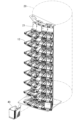
- FIG. 1 is a perspective view of a medicine dispensing device according to an embodiment of the present invention.
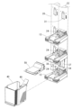
- FIG. 3 is a partial perspective view of a tablet feeder arranged on a drum.
- FIG. 3 is a sectional view of a tablet falling path in a tablet supply section.
- FIG. 3 is a perspective view showing a mounting portion of a count cassette.
- FIG. 3 is a perspective view of the mounting section in which the count cassette is mounted, viewed diagonally from behind.
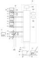
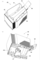
- a block diagram of a control unit A perspective view (a) of the count cassette seen from diagonally above, and a perspective view (b) seen from diagonally below.
- FIG. 3 is a partial perspective view of a tablet feeder arranged on a drum.
- FIG. 3 is a sectional view of a tablet falling path in a tablet supply section.
- FIG. 3 is a perspective view showing a mounting portion of a count cassette.
- FIG. 3(a) is an exploded perspective view of the support portion and lock portion of the count cassette as seen from the outside;
- FIG. An exploded perspective view (a) as seen from above and an exploded perspective view (b) as seen from below of the tablet receiving guide member.
- FIG. 3 is a sectional view showing the state of the tablet receiving portion (a) before the counting cassette is attached, and the state (b) of the tablet receiving portion when the counting cassette is attached.
- FIG. 3 is a cross-sectional view showing a cover that prevents tablets from bouncing off the tablet receiver.
- Flowchart showing inventory control. 15 is a flowchart of the tablet dispensing process in FIG.
- FIG. 14 is a flowchart of the tablet return process in FIG. 14.
- Flowchart of count clear processing The figure which shows the transition of a count mode screen.
- the figure which shows the transition of the count mode screen following FIG. The figure which shows the transition of a pill return screen.
- the figure which shows the transition of a count clear screen The figure which shows the transition of the count clear screen following FIG.
- the front view (a) and top view (b) which show arrangement
- FIG. 1 shows a medicine dispensing device 1 that uses a counting cassette according to an embodiment of the present invention.
- the drug dispensing device 1 includes a tablet supply unit 5 consisting of a first tablet supply section 3 provided inside the main body 2 and a second tablet supply section 4 provided outside the device main body 2, a manual dispensing unit 6, and a dispensing unit 6. It includes a unit 7, a tablet filling table 8, a barcode reader 9, a control unit 10, and the like.
- the first tablet supply section 3 is composed of a tablet cassette 11 and a mounting section 12 to which the tablet cassette 11 can be attached and detached. They are arranged on the outer surface in multiple rows in the circumferential direction and in multiple stages in the axial direction.
- each tablet cassette 11 includes a cassette body 14 in which a tablet accommodating section 13 for accommodating a large number of predetermined tablets is formed, and a cassette body 14 that is rotatably provided at the bottom of the tablet accommodating section 13 and a plurality of tablet cassettes.
- This is a known rotor 16 that includes a rotor 16 in which a tablet guide groove 15 is formed, and a partition member 17 that partitions the tablet guide groove 15 of the rotor 16.
- An RFID tag 19 is attached to the tablet cassette 11 as an identification device.
- RFID radio frequency identification
- the RFID tag 19 contains at least one of the identification information of the tablet cassette 11, the drug type identification information of the tablets stored in the tablet cassette 11, or the address of information regarding the tablet cassette 11 recorded in the storage unit 102. written.
- barcodes such as ITF (Interleaved Two of Five) can also be used as identification devices.
- Each mounting section 12 is provided in the form of a shelf on the outer wall 21 of the drum 20, and includes a drive motor 22 for driving the rotor 16 of the tablet cassette 11 and an RFID tag as a reading device for reading the RFID tag 19 of the tablet cassette 11.
- a reader/writer 23 is built-in.
- a tablet ejection path 24 communicating with the tablet outlet 18 of the tablet cassette 11 is formed in the mounting portion 12 .
- the tablet discharge path 24 is provided with a tablet detection sensor 25 that detects tablets discharged from the tablet outlet 18.
- the second tablet supply section 4 is disposed outside the main body and is composed of a universal tablet cassette 26 and a mounting section 27 to which the universal tablet cassette 26 can be attached and detached.
- a total of 8 sets of 8 stages x 1 column are provided.
- the wall 21 of the drum 20 to which the mounting section 12 of the first tablet supply section 3 is attached has a tablet ejection port that communicates with the tablet ejection path 24 of the mounting section 12 of the first tablet supply section 3. 31 is formed. Further, on the back surface of the wall portion 21 of the drum 20, tablet drop paths 32 are provided for each row of the first tablet supply section 3, respectively. The lower end of the tablet falling path 32 is received by a guide hopper 33 (see FIG. 25) of the packaging unit 7, so that the tablets supplied from the first tablet supply section 3 can be packaged in the packaging unit 7. Each tablet falling path 32 communicates with each tablet ejection path 24 of the mounting section 12 of the first tablet supply section 3 via the tablet ejection port 31 .
- a count cassette insertion opening 34 into which a tablet receiving section 49 of a count cassette 40 (described later) is inserted is formed in the wall portion 21 of the drum 20 to which the lowest mounting section 12 of the first tablet supply section 3 is attached.
- the count cassette insertion port 34 communicates with the tablet drop path 32 and has the same width as the tablet drop path 32.
- each tablet ejection port 31 a tablet that falls from above on a tablet fall path 32 enters the tablet ejection path 24 from the tablet ejection port 31, bounces off the slope of the tablet ejection path 24, and slows down the fall.
- a rebound prevention member 35 is provided to prevent this.
- the rebound prevention member 35a provided at the tablet ejection port 31 of the mounting section 12 located at the lowest position of the first tablet supply section 3 is attached by a hinge 36 so that the upper end thereof can be rotated in a direction away from the wall section 21. It has a movable plate 37 that opens and closes the cassette insertion port 34 from inside the tablet drop path 32.
- the rebound prevention member 35a having the movable plate 37 is biased by a spring means (not shown) in a direction in which the movable plate 37 closes the count cassette insertion opening 34.
- a count cassette detection sensor for detecting that a count cassette 40 (described later) is attached to the wall 21 of the drum 20 to which the lowest attachment section 12 of the first tablet supply section 3 is attached. 38 are provided.
- the count cassette detection sensor 38 includes a detection rod 38a that moves downward upon contact with the engagement portion 56 of the count cassette 40, and a sensor portion 38b that detects movement of the detection rod 38a.
- the hand-distributing unit 6 stores tablets in a large number of mass-shaped hand-distributing portions, opens the bottom of each mass, supplies the tablets to the packaging unit 7, and distributes the tablets at each predetermined dosing period. This is a known method.
- the packaging unit 7 is a known unit that packages tablets supplied from a tablet supply unit 5 consisting of a first tablet supply section 3 and a second tablet supply section 4 and a manual dispensing unit 6 into medicine packaging sheets for each administration period. be.
- the tablet filling table 8 is provided at the front of the device main body 2, and can place the tablet cassette 11, the universal cassette 31, and the counting cassette 40. As shown in FIG. 5, the tablet filling table 8 is equipped with an RFID reader/writer 39 as a reading device.
- the RFID reader/writer 39 reads the identification information of the tablet cassette 11 and the universal tablet cassette 31 written in the RFID tag 19 of the tablet cassette 11 and the RFID tag (not shown) of the universal tablet cassette 31, or the identification information of the tablet cassette 11 and the universal tablet cassette 31. It is possible to read or rewrite the drug type identification information, etc. of the tablets stored in the universal tablet cassette 31, and it is also possible to write or rewrite the code number and the drug to be inventoried on the RFID tag 47 of the count cassette 40. can.
- the barcode reader 9 is provided on the front of the device main body 2 above the tablet filling table 8, and can read the barcodes on the drug cases and medicine bottles as well as the barcodes 53 on the count cassettes 40.
- control unit 10 is a personal computer in the embodiment of FIG. 1, it is not limited to this. As shown in FIG. 6, the control unit 10 includes a control section 101, a storage section 102, a display section 103, and an input section 104 such as a keyboard.
- the control unit 10 includes a drive motor 22 provided in the mounting portion 12 of the tablet cassette 11, a drive motor (not shown) provided in the mounting portion 32 of the universal tablet cassette 31, a tablet detection sensor 25, an RFID reader/writer 23, A drug supply process that cooperates with the count cassette detection sensor 38, barcode reader 9, and RFID reader/writer 39 to control the tablet supply unit 5 and manual dispensing unit 6 to supply tablets and powdered medicine to the packaging unit 7; A drug packaging process in which supplied drugs are packaged according to the time of administration, and an inventory process in which the tablets remaining in the tablet supply unit 5 are counted and inventoried.
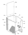
- the counting cassette 40 includes a container body 41, a buffer plate 42, and a tablet receiving guide member 43.
- the container main body 41 is a substantially rectangular container having an opening 41a at the top, and has a shape that can be attached to the mounting portion 12 in the same manner as the tablet cassette 11. That is, the container body is formed so that it can be installed in the mounting section 12 in exchange for the tablet cassette 11.
- the container body includes a bottom part 41b, a front part 41c located on the front side when attached to the mounting part 12, a left side part 41d and a right side part 41e located on the left and right sides, and a back part 41f located on the back side. These constitute a accommodating portion that can accommodate tablets.
- the bottom portion 41b of the container body 41 is provided with a guide 44 for positioning in the mounting portion 12 of the tablet cassette 11.
- a groove 41g is formed on the inner surface of the bottom portion 41b of the container body 41, and the groove 41g engages with the lower end of a buffer plate 42, which will be described later, between the bottom portion 41b and the front portion 41c.
- the front part 41c of the container main body 41 has an outwardly convex shape, and a gap is formed between the front part 41c and the buffer plate 42 mounted inside.
- the material of the impact plate 42 polycarbonate, acrylic, hard vinyl chloride, chlorinated vinyl chloride, etc. can be used.
- An engagement hole 41h for attaching the buffer plate 42 is formed in the left side part 41d and right side part 41e of the container body 41 at a position close to the front part 41c.
- An engaging portion 41i is formed on the back surface 41f of the container body 41, with which the detection rod 38a of the count cassette detection sensor 38 engages when the count cassette 40 is mounted on the mounting portion 12.
- the back surface 41f of the container body 41 has a notch 41j cut out downward from the opening 41a.
- the support portion 45 has a shape that projects horizontally in and out of the back surface portion 41f.
- a substantially plus (+)-shaped engagement protrusion 45a is formed on the upper surface of the support portion 45, with which the engagement recess 52a of the tablet receiving guide member 43 engages.
- a fitting hole 45b into which the pair of protrusions 52f of the tablet receiving guide member 43 fits is formed on the inside of the support portion 45 from the top surface downward.
- a through hole 45c into which the spring 57 is inserted is formed horizontally from both sides.
- a shaft hole 45d into which the shaft portion 54 of the lock portion 51 is inserted is formed in the outwardly projecting end surface of the support portion 45 in a direction perpendicular to the through hole 45c.
- the count cassette 40 is provided with a barcode 46 shown in FIG. 6 on the front part 41c, and an RFID tag 47 shown in FIG. 7(b) is attached to the bottom part 41a.
- a code number is recorded as identification information of the count cassette 40.
- Identification information of the count cassette 40 is written into the RFID tag 47.
- the buffer plate 42 is a rectangular plate attached to the inside of the front part 41c of the container body 41. Convex portions 42a that engage with the engagement holes 41h of the container body 41 are formed on both side edges of the buffer plate 42.
- the tablet receiving guide member 43 includes a tablet guide portion 48, a tablet receiving portion 49, a leaf spring 50, and a lock portion 51 (see FIG. 9(a)).
- the tablet guide section 48 has a base 52 and a guide plate 53.
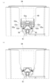
- An engaged recess 52a that engages with the engagement protrusion 45a of the support section 45 of the container body 41 is formed on the bottom surface of the base 52 of the tablet guide section 48. As shown in FIG. 11(a), the engaged recess 52a is wider than the support portion 45 of the container body 41, and there is a lock portion between both side surfaces of the support portion 45 and the inner surface of the engaged recess 52a.
- a space 52b is formed in which 51 elastic pieces 55 are accommodated.
- Engagement holes 52c in which the claw portions 55a of the elastic pieces 55 of the lock portion 51 engage, are engaged with both side walls of the engaged recess 52a.
- a groove 52g is formed in the outer end surface of the base 52, into which one end of a leaf spring 50, which will be described later, is inserted and supported.
- a shaft hole 52h is formed in the bearing portion 52d.
- the guide plate 53 of the tablet guide section 48 is formed integrally with the base 52, and extends downward from the upper surface of the base 52 toward the inside of the counting cassette 40 by 14.0 to 18.0 degrees, preferably 16.0 degrees. It is inclined at an angle and extends to the front part 41c of the container body 41. As shown in FIG. 8, the guide plate 53 is formed to be wide from the base 52 toward the tip, and is sloped downward toward both sides. As shown in FIG. 10(b), the back surface of the guide plate 53 is provided with two reinforcing ribs 53a extending from the base 52 to the tip, and near the base 52 is a fitting hole for the support portion 45 of the container body 41. A pair of protrusions 53b that fit into the protrusions 45b are provided.
- the tablet receiving part 49 is composed of an upper part 49a, a lower part 49b, a tip part 49c, both side parts 49d and 49e, and a plurality of ribs 49f extending from the inner surface of the upper part 49a to the tip part 49c, and has a rectangular shape when viewed from above. It has the shape of A shaft portion 49g is formed at one end of both side portions 49d and 49e to protrude outward. A gap 49h is formed between the upper part 49a and the lower part 49b, into which a leaf spring 50, which will be described later, is inserted.
- the tablet receiving portion 49 is rotatable about the shaft portion 49g by fitting the shaft portion 49g into the shaft hole 52h of the base portion 52.
- leaf spring 50 One end of the leaf spring 50 is supported by the groove 52g of the base 52, and the other end is inserted and supported in the gap 49h of the tablet receiving portion 49 to hold the tablet receiving portion 49 in a substantially horizontal state. In the horizontal state, the stopper 49i of the tablet receiving portion 49 is in contact with the bearing portion 52d. Further, the leaf spring 50 biases the tablet receiving portion 49 downward when the tablet receiving portion 49 rotates upward. Note that a coil spring may be used instead of the leaf spring 50.
- the lock portion 51 has a shaft portion 54 and an elastic piece 55.
- the shaft portion 54 is inserted into the shaft hole 45d of the support portion 45 of the container body 41, and is secured with a screw 56.
- the elastic piece 55 extends in a U-shape from the lower surface of the shaft portion 54 on both sides and enters the space 52b between the support portion 45 of the container body 41 and the engaged recess 52a of the base portion 52.
- An engagement claw 55a that engages with the engagement hole 52c of the base 52 is formed at the tip of the outer surface of the elastic piece 55.
- a spring locking portion 55b that supports both ends of the spring 57 is formed on the inner surface of the elastic piece 55.
- a knob portion 55c is formed on the side edge of the elastic piece 55 and projects in the axial direction of the shaft portion 54.
- the tablet receiving guide member 43 can be prevented from coming off from the container body 41 because the engaging claw 55a of the lock portion 51 is engaged with the engaging hole 52c. Further, the tablet receiving guide member 43 can be removed from the container body 41 since the engaging claw 55a disengages from the engaging hole 52c when the knob 55c of the locking portion 51 is pressed. By removing the tablet receiving guide member 43, the inside of the container body 41 and the tablet receiving guide member 43 itself can be easily cleaned. As shown in FIG. 11(b), the container body 41 from which the tablet receiving guide member 43 has been removed is expanded by the spring 57 of the lock portion 51, and has a width wider than the count cassette insertion opening 34. Therefore, the counting cassette 40 cannot be mounted on the mounting section 12 without the tablet receiving guide member 43 attached. For this reason, forgetting to attach the tablet receiving guide member 43 can be prevented.
- the tablet receiving part 49 of the tablet receiving guide member 43 is inserted into the tablet falling path 32 through the counting cassette insertion opening 34 of the drum 20 when the counting cassette 40 is installed in the mounting part 12.
- the width of the tablet receiving portion 49 is such that it can be inserted into the counting cassette insertion port 34 of the wall portion 21 of the drum 20, but when inserted into the counting cassette insertion port 34, the width of the tablet receiving portion 49 is such that it can be inserted into the counting cassette insertion port 34 of the wall portion 21 of the drum 20.
- the dimensions are such that tablets do not fit into the gaps.
- the protruding length of the tablet receiving part 49 is larger than the depth dimension of the tablet falling path 32, so that when it is inserted into the counting cassette insertion port 34, it comes into contact with the inner surface of the tablet falling path 32 and bends upward. ing.
- a tablet packaging path 60A is formed.
- a tablet receiving path 60B is formed from the outlet 18 to the tablet ejecting path 24 of the mounting base 12, the tablet ejecting port 31, the tablet falling path 32, the tablet receiving portion 49 of the counting cassette 40, the tablet guide portion 48, and the inside of the counting cassette 40. be done.
- the counting cassette 40 Since the counting cassette 40 is installed in the mounting section 12 in exchange for the tablet cassette 11, there is no need to provide a special installation space, and when the counting cassette 40 is installed in the mounting section 12, the tablet receiving section 49 is Since the tablet receiving path 60B is formed by being inserted into the falling path 32, there is no need to provide a special ejection path.
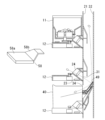
- the tablet receiving section 49 of the counting cassette 40 has a gentle slope and is lower than the counting cassette insertion port 34. It is in position. Therefore, as shown in FIG. 12(b), when the count cassette 40 is placed on the mounting part 12 and pushed forward, the rebound prevention member 35a is pushed and the tablet receiving part 49 is inserted into the count cassette insertion slot 34. . When the count cassette 40 is further pushed in, the tip of the tablet receiving part 49 hits the tablet falling path 32, and the reaction force pushes it upward against the biasing force of the leaf spring 50, making the inclination angle steeper.
- the tablet receiving portion 49 remains in contact with the tablet falling path 32 by the leaf spring 50, no gap is created. Furthermore, since the slope of the tablet receiving section 49 is steep, the tablets dispensed from the upper tablet cassette 11 hit the tablet receiving section 49 and forcefully enter the counting cassette 40, so that the tablets do not get stuck at the entrance of the counting cassette 40. do not have. When the count cassette 40 is removed from the mounting section 12, the tablet receiving section 49 returns to its original state with a gentle slope due to the biasing force of the leaf spring 50.
- the tablets that hit the tablet receiving part 49 do not enter the counting cassette 40, but bounce upward and enter the upper tablet ejection port 31. There is a possibility that it will jump out from there.
- the RFID reader/writer 23 determines whether or not there is a tablet cassette 11 in the mounting section 12 that is one level above the mounting section 12 to which the counting cassette 40 is mounted. prompts the user to attach the pill cassette 12 or the pop-out prevention cover 58.
- the pop-out prevention cover 58 is provided with an RFID tag, and by detecting this RFID tag with the RFID reader/writer 23, it is determined that the pop-out prevention cover 58 is attached, and the tablet count mode, which will be described later, is entered. It's okay.
- the pop-out prevention cover 58 has a base portion 58a that can be attached to the mounting portion 12 similarly to the tablet cassette 11, and a closing portion 58b that is a means for closing the tablet ejection path 24.
- the tablet cassette 11 or the pop-out prevention cover 64 By attaching the tablet cassette 11 or the pop-out prevention cover 64 to the attachment part 12 that is one level above the attachment part 12 to which the count cassette 40 is attached, the tablets that have rebounded from the tablet receiving part 49 are prevented from exiting from the upper tablet ejection port 31. It can prevent it from flying out.
- the count cassette 40 can be used for inventory using the tablet counting function of the medicine dispensing device 1 without transferring the tablets in the tablet cassette 11 to a tablet counter.
- the operator opens the front door of the drug dispensing device 1, manually moves the drum 20, moves the shelf in the row containing the tablet cassettes containing the tablets to be inventoryed toward the front, and moves the shelf to the top of the row.
- the tablet cassette 11 mounted on the lower mounting section 12 is removed, and the counting cassette 40 is inserted into the mounting section 12 in exchange for the tablet cassette 11.
- the tablet receiving portion 49 of the counting cassette 40 presses the movable plate 37 from the counting cassette insertion opening 34 of the drum 20 and enters the tablet falling path 32.
- each tablet cassette 11 the tablet ejection path 24 of the mounting base 12, the tablet ejection port 31, the tablet fall path 32, the tablet receiving part 49 of the counting cassette 40, the tablet guide part 48, and the counting cassette 40. Since the tablet receiving path 60B leading to the inside is formed, the tablets in each tablet cassette 11 can be received by the counting cassette 40. Note that the tablet cassette 11 mounted on the mounting section 12 one level above the mounting section 12 on which the counting cassette 40 is mounted is removed, and a pop-out prevention cover 58 is mounted in its place.
- control section 101 of the control unit 10 determines that the count cassette 40 has been inserted based on the signal from the count cassette detection sensor 38 of the drum 20 in step 101 shown in FIG.
- the screen changes to a count mode screen 110 shown in FIG. 18(a).
- the count mode screen 110 displays a message display section 111 and a cassette display section 112 that displays the shelf number of the row in which the count cassette 40 is inserted and the drug name of the tablet.
- a shelf switching button 113 consisting of " ⁇ " and “ ⁇ ” for changing the column of pill cassettes, a count end shelf number display section 114 that displays the shelf number at which counting has ended, a "start” button 115, and an "end” button.
- a button 116 and a "return” button 117 are provided.
- the cassette display section 112 initially displays the shelf number and drug name of the tablet cassette 11 installed in the row in which the count cassette 40 is installed.
- a shelf on which no tablet cassette 11 is mounted is left blank.
- step 103 the control unit 101 determines whether or not a tablet has been selected.
- step 104 the control unit 101 records the code number of the count cassette 40 and the inventory target on the RFID tag 47 of the count cassette 40.
- step 105 the code number of the counting cassette 40 and the drug type identification information of the inventory drug (or the cassette containing the target drug) are written in association with the drug type identification information of the inventory drug stored in the tablet cassette 11. identification information) and are stored in the storage unit 102 in association with each other.
- step 106 the control unit 101 highlights the selected shelf number and drug on the count mode screen 110, and activates the "start" button 115, as shown in FIG. 18(b). .
- step 107 the control unit 101 determines whether or not the "start" button 115 has been pressed. When the "start” button 115 is pressed, the control unit 101 performs a tablet dispensing process in step 108.
- step 201 the drive motor 22 of the mounting section 12 in which the tablet cassette 11 to be inventory is mounted is driven, and in step 202, the tablet outlet of the tablet cassette 11 to be inventory is driven.
- step 202 the tablet outlet of the tablet cassette 11 to be inventory is driven.
- the tablets ejected from the tablet outlet 18 are detected based on the signal from the tablet detection sensor 25 , and the number of tablets is stored in the storage section 102 in step 203 .
- step 204 when it is determined that the tablet ejection is completed based on the signal from the tablet detection sensor 25, in step 205, the drive motor 22 of the mounting section 12 in which the tablet cassette 11 to be inventoryed is mounted is stopped. .
- Whether or not tablet ejection is completed is determined by (1) rotor 16 or drive motor 22 rotating for a certain period of time without tablet detection sensor 25 turning on, or (2) tablet detection sensor 25 not turning on. This can be determined based on whether the rotor 16 or the drive motor 22 has rotated at a certain angle.
- a message "Counting in progress” is displayed on the message display section 111 of the count mode screen 110, as shown in FIG. 23(a). Further, when the tablet dispensing process is completed, a message “Counting completed” is displayed on the message display section 111, as shown in FIG. 23(b). Furthermore, when the counting cassette 40 is pulled out before the tablet dispensing process, a message “No counting cassette is inserted” is displayed on the message display section 111, as shown in FIG. 24(a).
- the operator When the tablet dispensing process is completed, the operator removes the count cassette 40 and places it on the tablet filling table 8 in order to return the tablets dispensed into the count cassette 40 to the tablet cassette 11.
- the control unit 101 performs the tablet return process of step 109, as shown in FIG.
- the RFID reader/writer 39 of the tablet filling table 8 reads the RFID tag 47 of the counting cassette 40, and in step 302, the screen transitions to the return filling screen 120 shown in FIG. do.
- the tablet cassette 11 to be inventoried may be read, or the "return" button 117 on the tablet count mode screen 110 may be used to transition to the return filling screen.
- the return filling screen 120 includes an "operator” display section 121, a “drug name 1 (cassette)” display section 122, a “drug name 2 (count cassette)” display section 123, and a “drug name 2 (count cassette)” display section 123.
- a “number of tablets” display section 124, a “return execution” button 125, and a “back” button 126 are displayed.
- step 303 the control unit 101 causes the RFID reader/writer 39 to read the RFID tag 47 of the count cassette 40 placed on the tablet filling table 8, and links it with the code number of the count cassette 40.
- the drug name in the count cassette 40 is displayed in the "drug name 2 (count cassette)" display section 123, and the tablets counted in the tablet dispensing process are displayed in the "number of tablets” display section 124. Show numbers.
- step 304 the control unit 101 determines whether an operator has been selected. If an operator has been selected, in step 305, the control unit 101 displays the selected operator in the “operator” display unit 121. indicate. In the first counting process, the "operator" display section 121 is blank and the operator can be selected from the operator list. In the second and subsequent counting processes, the previously selected operator is automatically input, so selection of the operator is not necessary.
- the operator takes out the dispensed tablet cassette 11 from the mounting section 12 and places it on the tablet filling table 8.
- the control unit 101 causes the RFID reader/writer 39 to read the RFID tag 19 of the tablet cassette 11 placed on the tablet filling table 8, and determines whether the tablet cassette 11 to be inventoried has been placed on the tablet filling table 8.
- the medicine type identification information of the RFID tag 19 of the tablet cassette 11 to be inventoried is read, and the medicine name of the tablet cassette 11 is displayed on the "drug name 1 (cassette)" display section 122.
- step 308 the control unit 101 checks whether the drug type identification information of the tablet cassette 11 to be inventory matches the drug type identification information linked to the code number of the count cassette 40, and in step 310 If the two match, a check OK is displayed on the return filling screen 120 in step 311, and the "execute return" button 125 is activated in step 312. If they do not match, a check NG is displayed on the return filling screen 120 in step 309, and the check processes in steps 306 to 308 are repeated until the correct tablet cassette 11 is placed.
- control unit 101 activates the "return execution” button 125 in step 312.
- the operator transfers the tablets from the counting cassette 40 to the tablet cassette 11 and presses the "return execution” button 125.
- control unit 101 determines that the "execute return” button 125 has been pressed in step 313, it ends the return process.
- step 111 the count end shelf number is displayed in the count end shelf number display section.
- the operator confirms the gray display of the inactive shelf number, drug name, and count repair shelf number, and presses the "end” button 116.
- step 113 the control unit 101 releases the link between the code number of the count cassette 40 stored in the storage unit 102 and the drug type identification information of the inventory drug.
- step 114 the inventory amount stored in the storage unit 102 is updated to the counted number of tablets, and in step 115, if there is no next inventory medicine, the counting mode is ended. Moreover, if there is the next inventory medicine in step 115, the process returns to step 103 and the same process is repeated.
- the state in which the medicine shelf number and medicine name are deactivated lasts for a preset duration.
- psychotropic drugs, poisonous drugs, powerful drugs, etc. are deactivated every day in order to take inventory every day, but other drugs remain inactive for a week.
- a new drug displayed on the cassette display section 112 of the count mode screen 110 may be selected while the count mode is not completed. This is a case where a medicine is mistakenly selected in an attempt to inventory the next tablet without returning the tablets dispensed to the counting cassette 40. In this case, if a new medicine is dispensed, there is a risk that the new tablets will be mixed in with the remaining tablets in the counting cassette 40. Therefore, in such a case, the control unit 101 performs count clear processing.
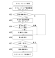
- FIG. 17 shows the count clearing process.
- the control unit 102 pops up a count clear confirmation screen 130 shown in FIG. 21(a) on the count mode screen 110.
- the count clear confirmation screen 130 displays the message "There is drug information before the return operation to the count cassette. Do you want to delete the drug information?", a "Yes” button 131, and a "No” button 132.
- control unit 101 determines that "Yes” has been selected for drug information deletion in step 402, it pops up the deletion method selection screen 140 shown in FIG. 21(b) on the count mode screen 110 in step 403.
- the erasing method selection screen 140 displays a message "Please confirm that there is no medicine in the count cassette and select the method for removing the medicine", a "Return” button 141, and a "Discard” button 142.
- step 404 the control unit 101 adds the number of tablets remaining in the count cassette 40 to the inventory amount in step 405, and proceeds to step 406.
- step 405 in order to inventory control the tablets in the medicine bottle stored in a place different from the drug dispensing device 1, when the tablets in the medicine bottle are put into the tablet cassette and counted, the remaining tablets remain in the counting cassette 40. Add the number of tablets in stock to the amount in stock. For example, assume that the current inventory is 400, including 200 in the pill bottle and 200 in the pill cassette, and as a result of counting in the count mode, there are 100 in the pill cassette. In this case, the inventory of tablet cassettes is updated from 200 to 100, and this is added to the 200 pill bottles to update the inventory to 300.
- the inventory amount is updated to the number of tablets remaining in the counting cassette 40 in step 405. For example, if the current inventory is 200 and the number of tablets counted in the count mode is 100, the inventory is updated to 100.
- the deletion method is "discard" in step 404, the number of tablets remaining in the count cassette 40 is not reflected in the inventory amount in step 405, and the process moves to step 406.
- this can be prevented from being reflected in the inventory amount by setting the deletion method to "discard". For example, assume that the current inventory is 400, including 200 in the pill bottle and 200 in the pill cassette, and as a result of counting in the count mode, there are 100 in the pill cassette. In this case, the tablet cassettes are to be discarded, so the inventory of tablet cassettes is updated from 200 to zero, and the remaining pill cassettes are updated to 200.
- the tablets remaining in the counting cassette can be discarded without being reflected in the amount of inventory. Update the inventory amount to zero.
- step 406 the control unit 101 activates the "operator” display section 151, the "decision” button 152, and the “back” button 153 on the count mode screen 110 shown in FIG.
- step 407 if the "decision" button 152 is pressed, the control unit 101 erases the drug information in the count cassette 40 and returns to the count mode screen 110, and if the "return” button 153 is pressed, the control unit 101 deletes the drug information from the count cassette 40. The process returns to the count mode screen 110 without erasing the drug information of 40.
- the medicines in the tablet cassettes 11 on other shelves can be selected on the cassette display section 111 and the counting process can be performed in the same way.
- the shelf switching button 113 to display shelf numbers and drug names in other columns, it is possible to select drugs in pill cassettes in other columns and perform counting processing in the same way. In this case, it is preferable to move the drum 20 so that the shelf in the row in which the selected tablet cassette 11 is mounted is in the front.
- one counting cassette 40 is installed in one row so that the counting cassette 40 receives and counts the pill cassettes 11 on the shelves in that row.
- the tablet cassettes 11 on the shelf in the row of rows may be received by other counting cassettes 40, so that the counting process of the tablet cassettes 11 in the plural rows can be performed simultaneously.
- the operator who performed the counting process, the medicine, and the processing date and time are recorded, and the list is displayed on a second display unit (not shown) (a display unit of a personal computer installed on the tablet filling table 8). It may be displayed or printed so that it can be confirmed who counted which drugs and when.
- the tablet cassette of the inner drum 20b is mounted on the mounting part of the outer drum 20a, and the tablet cassette of the inner drum 20b is mounted on the mounting part 11 of the outer drum 20a.
- the counting process may be performed using a counting cassette 40 attached to the machine. In this case, it is preferable to display the tablet cassettes 11 on the shelf of the inner drum 20b on the cassette display section 112, and to display a message prompting the user to attach the cassette 11 of the inner drum 20b to the specified attachment section 12 of the outer drum 20a. .
- Tablets may remain in the tablet cassette 11 after the counting process has been completed, but in this case, it is convenient to manually take out the remaining tablets from the tablet cassette 11 and insert them into the counting cassette 40. Therefore, on the count mode screen 110, it may be possible to add the number of remaining tablets to the counted number of tablets.
- An LED display section is provided in the mounting section 12 of the tablet cassette 11, and the LED of the mounting section 12 of the tablet cassette 11 is lit during the counting process, the LED blinks when the counting process is completed, and the LED is displayed when the counting process is completed. It may be displayed by lighting in a different color.
- the tablet information associated with the count cassette 40 and the tablet information in the tablet cassette 11 are collated on the tablet filling table 8, but instead of performing the collation on the tablet filling table 8, when the counting is finished. It is detected that the tablet cassette 11 is removed from the mounting base 8 and the tablets in the count cassette 40 are returned and mounted on the same mounting base 8, and the tablet information associated with the count cassette 40 and the tablets in the tablet cassette 11 are displayed. The association with the information may be canceled and the inventory amount may be updated to the counted number of tablets.
- the barcode reader 9 reads the tablet information of the pill bottle of the tablet to be added to the count cassette 40 and collates the medicine information linked with the count cassette 40. Further, if the amount of inventory is less than a preset amount, it is determined that the amount of inventory is low, and an alarm is issued. At this time, the operator may put tablets from the pill bottle into the tablet cassette for additional filling, dispense the tablets into the counting cassette, and update the inventory amount by adding the number of additional fillings.
- a list of the inventory drug shelf numbers, drug names, and number of tablets counted may be printed in a journal.
- the drive motor 22 of the mounting section 12 in which the tablet cassette 11 to be inventoryed is mounted is driven at a higher speed in the counting mode than in normal tablet dispensing in order to shorten the counting processing time.
- the medicine dispensing device 1 has been described with tablet cassettes arranged in a drum shape. It can also be used for inventory of drug dispensing devices.
- the variable tablet cassette is a known one that can adjust the width and depth of the tablet guide groove of the rotor and the height of the partition member according to the size and shape of the tablets accommodated in the tablet accommodating section (for example, (Refer to Japanese Unexamined Patent Publication No. 2018-126528).
Landscapes
- Health & Medical Sciences (AREA)
- Chemical & Material Sciences (AREA)
- Medicinal Chemistry (AREA)
- Pharmacology & Pharmacy (AREA)
- Life Sciences & Earth Sciences (AREA)
- Animal Behavior & Ethology (AREA)
- General Health & Medical Sciences (AREA)
- Public Health (AREA)
- Veterinary Medicine (AREA)
- Medical Preparation Storing Or Oral Administration Devices (AREA)
- Basic Packing Technique (AREA)
Abstract
Description
在庫錠剤をロードセルで計測して1錠単位の重さで割って在庫数を求めることができるが、錠剤のロット単位で1錠単位の重さが変わるために正確な計数ができなかった。
錠剤カセットが装着される装着部が複数配列され、前記錠剤カセットから錠剤が錠剤落下経路に排出され包装される薬剤払出装置において、
表示部と、カウントカセットとを備え、
前記カウントカセットが装着されると、前記カウントカセットより上方の前記錠剤カセットから排出されて前記錠剤落下経路を落下してくる錠剤を前記カウントカセットで受け取るように構成され、
前記カウントカセットが装着されると、前記表示部に錠剤カウントモード画面を表示する錠剤カウントモード画面表示手段と、
前記錠剤カウントモード画面に基づいて、前記錠剤カセットに収容された錠剤の数をカウント処理し、当該カウント数を前記錠剤カウントモード画面に出力するカウント処理手段とを備えることを特徴とする。
カウントカセットを装着すると錠剤カウントモード画面が表示されるので、当該錠剤カウントモード画面の表示及び操作に基づいて、他の錠剤カセットを装着したまま、薬剤払出装置のカウント機能を利用してカウント処理が行えるので、棚卸処理を効率的に行うことができる。
前記錠剤カウントモード画面に表示された薬剤が選択されると、当該選択薬剤と前記カウントカセットとの紐付けを行い、前記選択薬剤の数のカウント処理を終了すると、当該選択薬剤と前記カウントカセットとの紐付けを解除する紐付け制御手段と、を備えることを特徴とする
(1)の薬剤払出装置。
錠剤カウントモード画面に表示された薬剤を選択するだけで、当該選択薬剤とカウントカセットとの紐付けを簡単に行うことができる。
前記カウントカセット又は前記錠剤カセットが前記錠剤充填台に載置されると、前記表示部に戻し充填画面を表示する戻し充填画面表示手段と、
前記戻し充填画面に、前記錠剤充填台に載置された前記カウントカセットと紐付けされた選択薬剤を表示する受取薬剤表示手段と、
前記戻し充填画面に、前記錠剤充填台に載置された前記錠剤カセットと関連付けされた元薬剤を表示する元薬剤表示手段と、
前記受取薬剤表示手段で表示された受取薬剤と、前記元薬剤表示手段で表示された元薬剤とが一致するか否かを判断する照合手段と、
前記照合手段が前記受取薬剤と前記受取薬剤が一致すると判断すると、その旨表示するとともに、前記戻し充填画面の戻し実行ボタンを有効にする照合結果表示手段と、を備えることを特徴とする(2)の薬剤払出装置。
カウントカセット又は錠剤カセットを錠剤充填台に載置すると、戻し充填画面が表示されるので、当該戻し充填画面の表示及び操作に基づいて、カウントカセットから錠剤カセットの照合及びカウントカセットから錠剤カセットへの錠剤の戻し作業を容易に行うことができる。
戻し充填画面に操作者が表示されるので、誰が棚卸作業を行ったか容易に確認することができる。
前記消去確認画面で前記選択薬剤の薬剤情報を消去することが選択されると、前記カウントカセット内の錠剤を前記錠剤カセットに戻したか、又は破棄したかを選択させる消去方法選択画面を表示する消去方法選択画面表示手段と、
前記消去方法選択画面で、前記カウントカセット内の錠剤を前記錠剤カセットに戻したことが選択されると、カウント数を在庫量に追加し、前記カウントカセット内の錠剤を破棄したことが選択されると、カウント数を在庫量に追加しない、カウント数処理手段と、を備えることを特徴とする(1)の薬剤払出装置。
カウントカセットに錠剤が入ったままの状態で次の薬剤が選択されても、消去確認画面と消去方法選択画面に基づいて、戻し作業とカウント数処理を適切に行うことができる。
前記錠剤カウントモード画面に、同じ列の前記錠剤カセットに収容された錠剤の一覧を表示する錠剤一覧表示手段と、
前記錠剤一覧表示手段に表示されていない他の列の前記錠剤カセットに収容された錠剤の一覧に切り換える錠剤一覧切換手段と、を備えることを特徴とする(1)の薬剤払出装置。
錠剤カウントモード画面に表示された同じ列の錠剤カセットに収容された錠剤の一覧により、棚卸対象の錠剤を容易に選択することができる。
カウント処理が終了した薬剤はカウント処理が終了していない薬剤と区別して表示されるので、カウント処理が終了した薬剤を誤って再度選択するのを防止することができる。
(9) 前記薬剤非アクティブ化手段により非アクティブ化された薬剤について、前記錠剤カウントモードが終了した後、所定時間非アクティブ化を持続するか否かを選択する薬剤非アクティブ化持続選択手段を備えることを特徴とする
(8)に記載の薬剤払出装置。
棚卸作業が継続して行われない場合、棚卸作業を再開したときに、カウント処理が終了した薬剤を誤って再度選択するのを防止することができる。
前記錠剤受け部は、前記カウントカセットの容器本体に対して着脱可能であることを特徴とする(1)の薬剤払出装置。
カウントカセット本体から錠剤受け部を取り外すことで、カウントカセット本体の内部及び錠剤受け部自体を容易に清掃することができる。
錠剤受け部が離脱されたカウントカセット本体を装着して、錠剤カセットから払い出された錠剤がカウントカセットに受け取られずに排出されるのを防止することができる。
容器本体41の左側面部41d及び右側面部41eには、正面部41cに近接した位置に、緩衝板42を取り付けるための係合穴41hが形成されている。
本実施形態の薬剤払出装置1では、錠剤カセット11の錠剤を錠剤カウンタに移し換えることなく、カウントカセット40を薬剤払出装置1の錠剤カウント機能を利用して棚卸することができる。
カウントモードが終了しない間に、カウントモード画面110のカセット表示部112に表示された新たな薬品が選択されることがある。これは、カウントカセット40に払い出された錠剤の戻し処理を行わずに、誤って次の錠剤の棚卸を行なおうとして薬品を選択した場合である。この場合、新たな薬品の払出処理を行うと、カウントカセット40内の残った錠剤に新たな錠剤が混じる危険性がある。そこで、このような場合、制御部101は、カウントクリア処理を行う。
ステップ405は、薬剤払出装置1とは別の場所に保管されている薬瓶の錠剤を在庫管理するために、薬瓶の錠剤を錠剤カセットに投入してカウントした場合において、カウントカセット40に残っている錠剤の数を在庫量に追加する。例えば、現在の在庫が400個で、その内訳が薬瓶に200個、錠剤カセットに200個であって、カウントモードでカウントした結果、錠剤カセットには100個あったとする。この場合、錠剤カセットの在庫を200個から100個に更新し、薬瓶の200個に足して在庫を300個に更新する。
薬剤払出装置1の錠剤カセットに収容されている錠剤のみを在庫管理する場合には、ステップ405で、カウントカセット40に残っている錠剤の数に在庫量を更新する。例えば、現在の在庫が200個でカウントモードでカウントした錠数が100個の場合、在庫を100個に更新する。
これは、薬剤払出装置1以外で別に管理している薬瓶の錠剤をカウントした場合、消去方法を「廃棄」にすることで、在庫量に反映させないようにすることができる。例えば、現在の在庫が400個で、その内訳が薬瓶に200個、錠剤カセットに200個であって、カウントモードでカウントした結果、錠剤カセットには100個あったとする。この場合、廃棄するので、錠剤カセットの在庫を200個からゼロ個に更新し、残った薬瓶の200個に在庫を更新する。
また、薬剤払出装置1の錠剤カセットに収容されている錠剤のみを在庫管理する場合で、在庫量が多い場合、カウントカセットに残っている錠剤を在庫量に反映させないで、廃棄することができ、在庫量をゼロに更新する。
2 装置本体
3 第1錠剤供給部
4 第2錠剤供給部
5 錠剤供給ユニット
8 錠剤充填台
9 バーコードリーダ
10 制御ユニット
11 錠剤カセット
12 装着部
19 RFIDタグ
31 錠剤排出口
32 錠剤落下経路
34 カウントカセット挿入口
40 カウントカセット
43 錠剤受けガイド部材
49 錠剤受け部
101 制御部
102 記憶部
103 表示部
110 カウントモード画面
120 戻し充填画面
130 カウントクリア確認画面
140 消去方法選択画面
Claims (11)
- 錠剤カセットが装着される装着部が複数配列され、前記錠剤カセットから錠剤が錠剤落下経路に排出され包装される薬剤払出装置において、
表示部と、カウントカセットとを備え、
前記カウントカセットが装着されると、前記カウントカセットより上方の前記錠剤カセットから排出されて前記錠剤落下経路を落下してくる錠剤を前記カウントカセットで受け取るように構成され、
前記カウントカセットが装着されると、前記表示部に錠剤カウントモード画面を表示する錠剤カウントモード画面表示手段と、
前記錠剤カウントモード画面に基づいて、前記錠剤カセットに収容された錠剤の数をカウント処理し、当該カウント数を前記錠剤カウントモード画面に出力するカウント処理手段とを備えることを特徴とする薬剤払出装置。 - 前記錠剤カウントモード画面に、前記カウントカセットが装着された列の前記錠剤カセットに収容された薬剤を選択可能に表示する薬剤表示手段と、
前記錠剤カウントモード画面に表示された薬剤が選択されると、当該選択薬剤と前記カウントカセットとの紐付けを行い、前記選択薬剤の数のカウント処理を終了すると、当該選択薬剤と前記カウントカセットとの紐付けを解除する紐付け制御手段と、を備えることを特徴とする請求項1に記載の薬剤払出装置。 - 前記カウントカセットと前記錠剤カセットが載置される錠剤充填台と、
前記カウントカセット又は前記錠剤カセットが前記錠剤充填台に載置されると、前記表示部に戻し充填画面を表示する戻し充填画面表示手段と、
前記戻し充填画面に、前記錠剤充填台に載置された前記カウントカセットと紐付けされた選択薬剤を表示する受取薬剤表示手段と、
前記戻し充填画面に、前記錠剤充填台に載置された前記錠剤カセットと関連付けされた元薬剤を表示する元薬剤表示手段と、
前記受取薬剤表示手段で表示された受取薬剤と、前記元薬剤表示手段で表示された元薬剤とが一致するか否かを判断する照合手段と、
前記照合手段が前記受取薬剤と前記受取薬剤が一致すると判断すると、その旨表示するとともに、前記戻し充填画面の戻し実行ボタンを有効にする照合結果表示手段と、を備えることを特徴とする請求項2に記載の薬剤払出装置。 - 前記戻し充填画面に、操作者を選択して表示する操作者表示手段を備えることを特徴とする請求項3に記載の薬剤払出装置。
- 前記選択薬剤と前記カウントカセットとの紐付けが解除される前に、前記選択薬剤と異なる他の薬剤が選択されると、前記表示部に前記選択薬剤の薬剤情報を消去するか否かの消去確認画面を表示する消去確認画面表示手段と、
前記消去確認画面で前記選択薬剤の薬剤情報を消去することが選択されると、前記カウントカセット内の錠剤を前記錠剤カセットに戻したか、又は破棄したかを選択させる消去方法選択画面を表示する消去方法選択画面表示手段と、
前記消去方法選択画面で、前記カウントカセット内の錠剤を前記錠剤カセットに戻したことが選択されると、カウント数を在庫量に追加し、前記カウントカセット内の錠剤を破棄したことが選択されると、カウント数を在庫量に追加しない、カウント数処理手段と、を備えることを特徴とする請求項1に記載の薬剤払出装置。 - 前記錠剤カセットが装着される前記装着部が複数配列され、
前記錠剤カウントモード画面に、同じ列の前記錠剤カセットに収容された錠剤の一覧を表示する錠剤一覧表示手段と、
前記錠剤一覧表示手段に表示されていない他の列の前記錠剤カセットに収容された錠剤の一覧に切り換える錠剤一覧切換手段と、を備えることを特徴とする請求項1に記載の薬剤払出装置。 - 前記錠剤一覧表示手段により表示された錠剤のうち、カウント処理が終了した薬剤をカウント処理が終了していない薬剤と区別して表示するとともに、非アクティブ化する薬剤非アクティブ化手段を備えることを特徴とする請求項6に記載の薬剤払出装置。
- 前記薬剤非アクティブ化手段により非アクティブ化された薬剤について、前記錠剤カウントモードが終了した後、所定時間非アクティブ化を持続する薬剤非アクティブ化持続手段を備えることを特徴とする請求項7に記載の薬剤払出装置。
- 前記薬剤非アクティブ化手段により非アクティブ化された薬剤について、前記錠剤カウントモードが終了した後、所定時間非アクティブ化を持続するか否かを選択する薬剤非アクティブ化持続選択手段を備えることを特徴とする請求項8に記載の薬剤払出装置。
- 前記カウントカセットに、前記カウントカセットを前記装着部に装着したときに前記錠剤落下経路に挿入される錠剤受け部を備え、
前記錠剤受け部は、前記カウントカセットの容器本体に対して着脱可能であることを特徴とする請求項1に記載の薬剤払出装置。 - 前記錠剤受け部が離脱された前記カウントカセットが、前記装着部に装着されるのを防止する手段を備えることを特徴とする請求項10に記載の薬剤払出装置。
Priority Applications (2)
| Application Number | Priority Date | Filing Date | Title |
|---|---|---|---|
| JP2024516287A JPWO2023204238A1 (ja) | 2022-04-20 | 2023-04-19 | |
| CN202380028449.6A CN118922163A (zh) | 2022-04-20 | 2023-04-19 | 发药装置 |
Applications Claiming Priority (2)
| Application Number | Priority Date | Filing Date | Title |
|---|---|---|---|
| JP2022069767 | 2022-04-20 | ||
| JP2022-069767 | 2022-04-20 |
Publications (1)
| Publication Number | Publication Date |
|---|---|
| WO2023204238A1 true WO2023204238A1 (ja) | 2023-10-26 |
Family
ID=88419902
Family Applications (1)
| Application Number | Title | Priority Date | Filing Date |
|---|---|---|---|
| PCT/JP2023/015576 Ceased WO2023204238A1 (ja) | 2022-04-20 | 2023-04-19 | 薬剤払出装置 |
Country Status (4)
| Country | Link |
|---|---|
| JP (1) | JPWO2023204238A1 (ja) |
| CN (1) | CN118922163A (ja) |
| TW (1) | TW202343471A (ja) |
| WO (1) | WO2023204238A1 (ja) |
Citations (3)
| Publication number | Priority date | Publication date | Assignee | Title |
|---|---|---|---|---|
| JP2021016598A (ja) * | 2019-07-22 | 2021-02-15 | 株式会社トーショー | 汎用薬剤供給装置及び薬剤分包装置 |
| JP2021166858A (ja) * | 2019-01-31 | 2021-10-21 | 株式会社湯山製作所 | 薬剤取扱装置 |
| WO2021210624A1 (ja) * | 2020-04-18 | 2021-10-21 | 株式会社湯山製作所 | 錠剤受取容器及び薬剤払出装置 |
-
2023
- 2023-03-28 TW TW112111746A patent/TW202343471A/zh unknown
- 2023-04-19 CN CN202380028449.6A patent/CN118922163A/zh active Pending
- 2023-04-19 WO PCT/JP2023/015576 patent/WO2023204238A1/ja not_active Ceased
- 2023-04-19 JP JP2024516287A patent/JPWO2023204238A1/ja active Pending
Patent Citations (3)
| Publication number | Priority date | Publication date | Assignee | Title |
|---|---|---|---|---|
| JP2021166858A (ja) * | 2019-01-31 | 2021-10-21 | 株式会社湯山製作所 | 薬剤取扱装置 |
| JP2021016598A (ja) * | 2019-07-22 | 2021-02-15 | 株式会社トーショー | 汎用薬剤供給装置及び薬剤分包装置 |
| WO2021210624A1 (ja) * | 2020-04-18 | 2021-10-21 | 株式会社湯山製作所 | 錠剤受取容器及び薬剤払出装置 |
Also Published As
| Publication number | Publication date |
|---|---|
| TW202343471A (zh) | 2023-11-01 |
| CN118922163A (zh) | 2024-11-08 |
| JPWO2023204238A1 (ja) | 2023-10-26 |
Similar Documents
| Publication | Publication Date | Title |
|---|---|---|
| US5852911A (en) | Tablet dispenser | |
| JP7590658B2 (ja) | 薬剤払出装置 | |
| JP5884856B2 (ja) | 錠剤フィーダ | |
| USRE40453E1 (en) | Enhanced drug dispensing system | |
| JP6798639B2 (ja) | 錠剤分包装置 | |
| WO2001034090A1 (fr) | Dispositif de remplissage de medicaments solides | |
| JP7141004B2 (ja) | 錠剤払出システム、錠剤払出制御プログラム | |
| JP2022059035A (ja) | 薬剤包装装置 | |
| JP3476648B2 (ja) | 自動販売機 | |
| EP0135631A1 (en) | Article dispensing apparatus and a method of dispensing articles | |
| WO2023204238A1 (ja) | 薬剤払出装置 | |
| JP2001129058A (ja) | 固形製剤充填装置 | |
| JP2024031492A (ja) | カウントカセット及び薬剤払出装置 | |
| JP2001129059A (ja) | 固形製剤充填装置 | |
| US6422417B1 (en) | Cigarette vending machine and vending machine dispenser | |
| JP2001276182A (ja) | 固形製剤充填装置 | |
| US1260372A (en) | Vending-machine. | |
| GB2248609A (en) | Apparatus for dispensing from top of stack | |
| JP2001129060A (ja) | 固形製剤充填装置 | |
| JP2022121252A (ja) | 錠剤払出システム、錠剤払出制御プログラム | |
| JP3254504B2 (ja) | 自動販売機の商品投出機構 | |
| JP2002263357A (ja) | ホッパ装置 | |
| JPH09117492A (ja) | 調剤業務用処理装置 | |
| JP2000113294A (ja) | 自動販売機 | |
| HK1207197B (en) | Manually-manipulated merchandise vending device |
Legal Events
| Date | Code | Title | Description |
|---|---|---|---|
| 121 | Ep: the epo has been informed by wipo that ep was designated in this application |
Ref document number: 23791886 Country of ref document: EP Kind code of ref document: A1 |
|
| ENP | Entry into the national phase |
Ref document number: 2024516287 Country of ref document: JP Kind code of ref document: A |
|
| WWE | Wipo information: entry into national phase |
Ref document number: 202380028449.6 Country of ref document: CN |
|
| NENP | Non-entry into the national phase |
Ref country code: DE |
|
| 122 | Ep: pct application non-entry in european phase |
Ref document number: 23791886 Country of ref document: EP Kind code of ref document: A1 |