WO2023204209A1 - 磁性体内蔵基板の製造方法、及び磁性樹脂組成物 - Google Patents
磁性体内蔵基板の製造方法、及び磁性樹脂組成物 Download PDFInfo
- Publication number
- WO2023204209A1 WO2023204209A1 PCT/JP2023/015463 JP2023015463W WO2023204209A1 WO 2023204209 A1 WO2023204209 A1 WO 2023204209A1 JP 2023015463 W JP2023015463 W JP 2023015463W WO 2023204209 A1 WO2023204209 A1 WO 2023204209A1
- Authority
- WO
- WIPO (PCT)
- Prior art keywords
- magnetic
- substrate
- sheet
- built
- manufacturing
- Prior art date
- Legal status (The legal status is an assumption and is not a legal conclusion. Google has not performed a legal analysis and makes no representation as to the accuracy of the status listed.)
- Ceased
Links
Images


Classifications
-
- H—ELECTRICITY
- H01—ELECTRIC ELEMENTS
- H01F—MAGNETS; INDUCTANCES; TRANSFORMERS; SELECTION OF MATERIALS FOR THEIR MAGNETIC PROPERTIES
- H01F1/00—Magnets or magnetic bodies characterised by the magnetic materials therefor; Selection of materials for their magnetic properties
- H01F1/01—Magnets or magnetic bodies characterised by the magnetic materials therefor; Selection of materials for their magnetic properties of inorganic materials
- H01F1/03—Magnets or magnetic bodies characterised by the magnetic materials therefor; Selection of materials for their magnetic properties of inorganic materials characterised by their coercivity
- H01F1/12—Magnets or magnetic bodies characterised by the magnetic materials therefor; Selection of materials for their magnetic properties of inorganic materials characterised by their coercivity of soft-magnetic materials
- H01F1/14—Magnets or magnetic bodies characterised by the magnetic materials therefor; Selection of materials for their magnetic properties of inorganic materials characterised by their coercivity of soft-magnetic materials metals or alloys
- H01F1/20—Magnets or magnetic bodies characterised by the magnetic materials therefor; Selection of materials for their magnetic properties of inorganic materials characterised by their coercivity of soft-magnetic materials metals or alloys in the form of particles, e.g. powder
- H01F1/22—Magnets or magnetic bodies characterised by the magnetic materials therefor; Selection of materials for their magnetic properties of inorganic materials characterised by their coercivity of soft-magnetic materials metals or alloys in the form of particles, e.g. powder pressed, sintered, or bound together
- H01F1/24—Magnets or magnetic bodies characterised by the magnetic materials therefor; Selection of materials for their magnetic properties of inorganic materials characterised by their coercivity of soft-magnetic materials metals or alloys in the form of particles, e.g. powder pressed, sintered, or bound together the particles being insulated
- H01F1/26—Magnets or magnetic bodies characterised by the magnetic materials therefor; Selection of materials for their magnetic properties of inorganic materials characterised by their coercivity of soft-magnetic materials metals or alloys in the form of particles, e.g. powder pressed, sintered, or bound together the particles being insulated by macromolecular organic substances
-
- H—ELECTRICITY
- H05—ELECTRIC TECHNIQUES NOT OTHERWISE PROVIDED FOR
- H05K—PRINTED CIRCUITS; CASINGS OR CONSTRUCTIONAL DETAILS OF ELECTRIC APPARATUS; MANUFACTURE OF ASSEMBLAGES OF ELECTRICAL COMPONENTS
- H05K3/00—Apparatus or processes for manufacturing printed circuits
- H05K3/46—Manufacturing multilayer circuits
Definitions
- the present disclosure generally relates to a method for manufacturing a substrate with a built-in magnetic material, and a magnetic resin composition used in this manufacturing method.
- Patent Document 1 discloses a method for manufacturing a hole-filling substrate.
- the hole filling substrate includes a support substrate in which a plurality of through holes are formed, and a filling layer formed in the through holes with a cured product of a resin composition.
- the method for manufacturing the hole-filling substrate described above includes the steps of printing a resin composition on a support substrate by the following printing method, and curing the resin composition.
- the above printing method includes an installation process, a supply process, a first printing process, and a second printing process.
- a mask having a hollow opening is installed on a support substrate having a plurality of through holes so that one opening communicates with two or more through holes.
- a resin composition containing an inorganic filler and a thermosetting resin is supplied to the surface of the mask opposite to the support substrate.
- the inorganic filler includes magnetic powder.
- the first squeegee is moved relatively along the surface of the mask so that a part of the first squeegee is pushed into the inside of the opening, and the first squeegee is moved through the mask.
- the hole is filled with a resin composition.
- a second squeegee which is the same as or different from the first squeegee, is moved relatively along the surface of the mask to apply the resin composition filled in the through holes. Apply a resin composition.
- the front surface (the surface of the support substrate on the mask side), the back surface (the surface of the support substrate opposite to the mask), and the front surface and back surface of the support substrate are Residues of the resin composition remain on the periphery of the through hole. This residue is formed outside the through hole, and requires a polishing process to remove it.
- An object of the present disclosure is to provide a method for manufacturing a magnetic material-embedded substrate and a magnetic resin composition that can omit or simplify the polishing step by making it difficult to leave magnetic material residue on the surface of the substrate. It is in.
- a method for manufacturing a magnetic substance built-in substrate includes a preparation step, a filling step, and a peeling step.
- a preparation step a surface protection substrate and a magnetic material are prepared.
- the surface protection substrate includes a substrate and a protection sheet disposed on the surface of the substrate and including a sheet body, and has a through hole passing through the substrate and the protection sheet.
- the filling step the magnetic material is filled into the through hole from the side of the protective sheet.
- the peeling step the sheet main body is peeled from the substrate.
- the magnetic resin composition according to one aspect of the present disclosure is included in the magnetic material used in the method for manufacturing the magnetic body built-in substrate.
- the magnetic resin composition contains magnetic powder and a thermosetting resin.
- the thermosetting resin includes at least one of an epoxy resin and an acid anhydride.
- FIGS. 1A to 1E are schematic cross-sectional views showing each step of the method for manufacturing a magnetic substance built-in substrate according to the first embodiment.
- FIGS. 2A to 2E are schematic cross-sectional views showing each step of a method for manufacturing a substrate with a built-in magnetic material according to the second embodiment.
- 3A to 3D are schematic cross-sectional views showing each step of a method for manufacturing a magnetic material-embedded substrate according to a third embodiment.
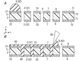
- FIG. 4A is a schematic cross-sectional view showing a method of manufacturing a magnetic substance built-in substrate according to a fourth embodiment.
- FIG. 4B is a schematic plan view of a frame used in the method for manufacturing the magnetic substance built-in substrate same as above.
- 5A and 5B are schematic cross-sectional views showing each step of a method for manufacturing a magnetic substance built-in substrate according to a fifth embodiment.
- the method for manufacturing the magnetic substance built-in substrate 1 includes a preparation process, a filling process, and a peeling process.
- a preparation step a surface protection substrate 5 and a magnetic material 6 are prepared (see FIG. 1A).
- the surface protection substrate 5 includes a substrate 2 and a protection sheet 3 disposed on the surface of the substrate 2 and including a sheet body 7.
- the surface protection substrate 5 has a through hole 4 that penetrates the substrate 2 and the protection sheet 3.
- the magnetic material 6 is filled into the through holes 4 from the protective sheet 3 side (see FIGS. 1B and 1C).
- the peeling step the sheet body 7 is peeled off from the substrate 2 (see FIG. 1D). In this way, the magnetic material built-in substrate 1 can be manufactured (see FIG. 1E).
- the surface of the substrate 2 is protected with a protective sheet 3 in the filling process. Therefore, contact of the magnetic material 6 with the surface of the substrate 2 is suppressed.
- the surface of the substrate 2 and the filling portion 60 filled in the through hole 4 are usually flush with each other. In this way, the magnetic resin composition does not adhere to the surface of the substrate 2. Therefore, the polishing step after the peeling step can be omitted.
- the magnetic material 6 slightly protrudes from the through hole 4. In this case, it is sufficient to polish only the magnetic material 6 protruding from the surface of the substrate 2, and there is no need to polish the entire surface of the substrate 2. Therefore, the polishing process can be simplified.
- the polishing process can be omitted or simplified by making it difficult for the residue of the magnetic material 6 to remain on the surface of the substrate 2.
- the method for manufacturing the magnetic substance built-in substrate 1 according to the present embodiment includes a preparation process, a filling process, and a peeling process. Below, these steps will be explained in order.
- the surface protection substrate 5 has a plate shape.
- the surface protection substrate 5 extends in the X-axis direction and the Y-axis direction, and has a thickness in the Z-axis direction.
- the surface protection substrate 5 has a first main surface 51, a second main surface 52, and at least one (in this embodiment, plural) through holes 4.
- the first principal surface 51 is a surface facing in the positive direction of the Z-axis.
- the second main surface 52 exists on the opposite side of the first main surface 51. That is, the second principal surface 52 is a surface facing in the negative direction of the Z-axis.
- the thickness T5 of the surface protection substrate 5 is equal to the distance between the first main surface 51 and the second main surface 52.
- the thickness T5 of the surface protection substrate 5 is not particularly limited, but is, for example, 0.3 mm or more and 2.0 mm or less.
- the through hole 4 penetrates from the first main surface 51 to the second main surface 52.
- the length of the through hole 4 in the Z-axis direction is equal to the thickness T5 of the surface protection substrate 5.
- the shape of the through hole 4 in the XY plane view is circular, but is not particularly limited.
- the diameter of the through hole 4 is, for example, 200 ⁇ m or more and 800 ⁇ m or less.
- the diameters of these through holes 4 may be the same or different.
- the through holes 4 are lined up in the X-axis direction and the Y-axis direction.
- the pitch between through holes 4 adjacent to each other in the X-axis direction and the pitch between through holes 4 adjacent to each other in the Y-axis direction are not particularly limited.
- the pitch is the center distance between adjacent through holes 4.
- the plurality of through holes 4 are arranged in the form of lattice points in the XY plane view, but the arrangement of the plurality of through holes 4 is not particularly limited.
- the surface protection substrate 5 includes a substrate 2 and one or two (two in this embodiment) protection sheets 3.
- the through hole 4 penetrates the substrate 2 and the protective sheet 3.
- the substrate 2 and the protective sheet 3 will be explained in order.
- the substrate 2 includes a plate-shaped insulating substrate having electrical insulation properties, and constitutes the main part of the surface protection substrate 5.
- the insulating substrate is not particularly limited as long as it has electrical insulation properties.
- the substrate 2 has a first main surface 21, a second main surface 22, and a through hole 4.
- the first main surface 21 is a surface facing in the positive direction of the Z-axis.
- the second main surface 22 exists on the opposite side of the first main surface 21. That is, the second principal surface 22 is a surface facing in the negative direction of the Z-axis.
- the through hole 4 penetrates from the first main surface 21 to the second main surface 22.
- the protective sheet 3 is a sheet that temporarily protects the surface of the substrate 2. At least a portion (the entirety in this embodiment) of the protective sheet 3 can be peeled off from the substrate 2 if necessary. Specifically, it is a sheet for suppressing the magnetic material 6 from coming into contact with the surface of the substrate 2 during the process of manufacturing the magnetic material built-in substrate 1 (see FIG. 1A).
- the protective sheet 3 extends in the X-axis direction and the Y-axis direction, and has a thickness in the Z-axis direction.
- the protective sheet 3 has through holes 4.
- the positions of the through holes 4 of the protective sheet 3 match the positions of the through holes 4 of the substrate 2 in the XY plane view.
- the diameter of the through hole 4 of the protective sheet 3 is equal to the diameter of the through hole 4 of the substrate 2.
- the protective sheet 3 is placed on the surface of the substrate 2.
- two protective sheets 3 first protective sheet 31 and second protective sheet 32 are used.
- the first protective sheet 31 is arranged on the first main surface 21 of the substrate 2. Note that the first main surface 51 of the surface protection substrate 5 is a surface of the first protection sheet 31 facing in the positive Z-axis direction.
- the second protective sheet 32 is arranged on the second main surface 22 of the substrate 2. Note that the second main surface 52 of the surface protection substrate 5 is a surface of the second protection sheet 32 facing in the negative Z-axis direction.
- the thickness of the protective sheet 3 is not particularly limited, but is, for example, 10 ⁇ m or more and 60 ⁇ m or less. As described above, when the thickness of the protective sheet 3 is 10 ⁇ m or more, the protective sheet 3 becomes difficult to be damaged, and the protective sheet 3 can be efficiently peeled off from the substrate 2. When two protective sheets 3 are used as in this embodiment, the thicknesses of these protective sheets 3 may be the same or different.
- the protective sheet 3 includes a sheet main body 7.
- the seat body 7 has a first main surface 71 and a second main surface 72.
- the first main surface 71 is a surface facing in the positive direction of the Z-axis.
- the second main surface 72 exists on the opposite side of the first main surface 71. That is, the second principal surface 72 is a surface facing in the negative direction of the Z-axis.
- the sheet body 7 includes at least one of a resin film and a metal foil.
- a resin film include, but are not limited to, polyethylene terephthalate (PET) films.
- PET polyethylene terephthalate
- the metal foil include, but are not limited to, copper foil and the like.
- the surface of the sheet body 7 in contact with the substrate 2 is subjected to a mold release treatment.
- examples of the protective sheet 3 in this case include a surface-release-treated resin film, a surface-release-treated metal foil, and the like.
- the surface of the sheet body 7 of the first protective sheet 31 that is in contact with the first main surface 21 of the substrate 2 is subjected to a mold release treatment.
- the surface of the sheet body 7 of the second protective sheet 32 that is in contact with the second main surface 22 of the substrate 2 is subjected to a mold release treatment.
- the mold release treatment is not particularly limited, but includes, for example, mold release treatment using a mold release agent such as a silicone resin mold release agent, an alkyd resin mold release agent, and a fluororesin mold release agent.
- a mold release agent such as a silicone resin mold release agent, an alkyd resin mold release agent, and a fluororesin mold release agent.
- a release layer (not shown) may be provided on the surface of the sheet body 7 that is in contact with the substrate 2 (the surface that faces the substrate 2).
- examples of the protective sheet 3 in this case include a resin film with a release layer, a metal foil with a release layer, and the like.
- the release layer may be either a known organic release layer or an inorganic release layer.
- the organic component contained in the organic release layer include nitrogen-containing organic compounds, sulfur-containing organic compounds, carboxylic acids, and the like.
- specific examples of the inorganic components contained in the inorganic release layer include metals or alloys consisting of at least one of Ni, Mo, Co, Cr, Fe, Ti, W, P, Zn, etc., and/or oxidation thereof. Things can be mentioned. In this way, since the peeling layer is provided on the surface of the sheet body 7 of the protective sheet 3 that contacts the substrate 2 (the surface facing the substrate 2), the protective sheet 3 can be easily peeled off from the substrate 2 if necessary. It has become.
- the magnetic material 6 is a material that becomes magnetized when placed in a magnetic field. In the process of manufacturing the magnetic material built-in substrate 1, the magnetic material 6 is filled into the through holes 4 of the substrate 2. In this embodiment, the magnetic material 6 is a magnetic sheet 61.
- the magnetic sheet 61 extends in the X-axis direction and the Y-axis direction, and has a thickness in the Z-axis direction.
- the magnetic sheet 61 is a magnetic resin composition formed into a sheet shape.
- the magnetic resin composition contains magnetic powder and a binder.
- the binder includes a thermosetting resin. Therefore, the magnetic sheet 61 has thermosetting properties.
- the binder may further contain at least one of a curing agent, a curing accelerator, a coupling agent, and a dispersant.
- the magnetic powder is not particularly limited, but includes, for example, permalloy, ferrite, Fe-Si alloy powder, pure iron powder (carbonyl iron powder), and the like.
- Permalloy is an Fe-Ni alloy.
- the ferrite include, but are not particularly limited to, manganese zinc ferrite (MnZn ferrite), manganese ferrite (Mn ferrite), nickel zinc ferrite (NiZn ferrite), magnetite (magnetite), and the like.
- the average particle diameter of the magnetic powder is preferably 0.1 ⁇ m or more, more preferably 0.3 ⁇ m or more.
- the average particle diameter of the magnetic powder is preferably 20 ⁇ m or less, more preferably 10 ⁇ m or less.
- the average particle size means the particle size at 50% of the integrated value in the particle size distribution measured using a particle size distribution measuring device based on a laser scattering/diffraction method, that is, the 50% volume average particle size (D50).
- the content of the magnetic powder is preferably 85% by mass or more, more preferably 92% by mass or more, based on the total amount of the magnetic resin composition.
- the content of the magnetic powder is preferably 97% by mass or less based on the total amount of the magnetic resin composition.
- the content of the magnetic powder is 97% by mass or less, it is possible to prevent the through holes 4 from being unfilled with the magnetic resin composition.
- relative magnetic permeability mainly means the real part ( ⁇ r ′) of the complex relative magnetic permeability ( ⁇ r ).
- the relational expression of the complex relative magnetic permeability ( ⁇ r ) can be summarized as follows. That's right.
- the thermosetting resin preferably contains at least one of an epoxy resin and an acid anhydride. Thereby, the glass transition temperature (Tg) and elastic modulus of the cured product of the magnetic resin composition can be increased.
- Epoxy resins are not particularly limited, but include, for example, bisphenol A epoxy resins, alicyclic epoxy resins, polyfunctional epoxy resins, bisphenol F epoxy resins, and the like.
- the acid anhydride is not particularly limited, but includes, for example, carboxylic acid anhydride.
- carboxylic anhydride include methylbicyclo[2.2.1]heptane-2,3-dicarboxylic anhydride, hexahydrophthalic anhydride, methylhexahydrophthalic anhydride, 1,2,3,6-tetrahydro Phthalic anhydride, methyltetrahydrophthalic anhydride, methylendomethylenetetrahydrophthalic anhydride, cyclohexane-1,2,4-tricarboxylic acid-1,2-anhydride, dodecenylsuccinic anhydride, succinic anhydride, hydrogenated pyromellitic anhydride
- Commercially available acid anhydrides include, for example,
- the magnetic sheet 61 preferably contains volatile components.
- Volatile components are components that have volatility and become gaseous in the atmosphere.
- volatile components include volatile organic compounds (VOC).
- VOC volatile organic compounds
- Examples of the volatile organic compound include, but are not limited to, methyl ethyl ketone (MEK), N,N-dimethylformamide (DMF), and the like.
- MEK methyl ethyl ketone
- DMF N,N-dimethylformamide
- the content of volatile components can be measured as the weight loss rate when the magnetic resin composition is heated at 160° C. for 15 minutes.
- the content of volatile components is preferably 0.05% by mass or more based on the total amount of the magnetic resin composition.
- the content of volatile components is preferably 1% by mass or less, more preferably 0.5% by mass or less, based on the total amount of the magnetic resin composition.
- generation of voids can be suppressed. That is, voids are less likely to occur in the magnetic resin composition filled in the through holes 4.
- the magnetic resin composition may contain additives to the extent that the effects of this embodiment are not impaired.
- additives include, but are not limited to, imidazole compounds (manufactured by Shikoku Kasei Kogyo Co., Ltd., trade name: 2MAOK-PW), amine compounds (manufactured by Tokyo Kasei Kogyo Co., Ltd., trade name: dicyandiamide), and silane coupling agents. , a dispersant, a surface conditioner (leveling agent), an adhesion agent, an antistatic agent, and the like.
- the melt viscosity of the magnetic sheet 61 at 175° C. is preferably 60 Pa ⁇ s or more, more preferably 80 Pa ⁇ s or more.
- the melt viscosity of the magnetic sheet 61 at 175° C. is 60 Pa ⁇ s or more, occurrence of molding defects such as resin leakage and burrs can be suppressed. Further, it is possible to promote the magnetic resin composition to enter the through hole 4.
- the melt viscosity of the magnetic sheet 61 at 175° C. is preferably 3000 Pa ⁇ s or less, more preferably 2500 Pa ⁇ s or less. By setting the melt viscosity of the magnetic sheet 61 at 175° C. to 3000 Pa ⁇ s or less, it is possible to prevent the through holes 4 from being unfilled with the magnetic resin composition. Note that the melt viscosity of the magnetic sheet 61 at 175° C. can be measured by the Koka type flow tester method.
- the thickness T61 of the magnetic sheet 61 is preferably 0.1 times or more, more preferably 0.2 times or more the thickness T5 of the surface protection substrate 5 (see FIG. 1A). By setting the thickness T61 of the magnetic sheet 61 to be 0.1 times or more the thickness T5 of the surface protection substrate 5, it is possible to prevent the through holes 4 from being unfilled with the magnetic resin composition. On the other hand, the thickness T61 of the magnetic sheet 61 is preferably 0.8 times or less, more preferably 0.6 times or less, the thickness T5 of the surface protection substrate 5. Since the thickness T61 of the magnetic sheet 61 is 0.8 times or less the thickness T5 of the surface protection substrate 5, warpage of the magnetic body built-in substrate 1 can be suppressed.
- the magnetic material 6 is filled into the through holes 4 from the protective sheet 3 side (see FIGS. 1A to 1C).
- the magnetic material 6 is filled into the through holes 4 from the first protective sheet 31 side.
- the through holes 4 are filled with the molten magnetic sheet 61 (liquid magnetic resin composition). The filling process will be explained in more detail below.
- a magnetic sheet 61 is stacked on the first main surface 51 of the surface protection substrate 5 to form a laminate 10 (see FIG. 1A). Specifically, the through hole 4 opening in the first main surface 51 is covered with a magnetic sheet 61. In this manner, the magnetic sheet 61 is present on the Z-axis positive side of the plurality of through holes 4 before hot pressing.
- release films 9 are stacked on both sides of the laminate 10 (see FIG. 1B).
- the release film 9 is used during hot pressing, and is peeled off from the laminate 10 after hot pressing.
- the release film 9 extends in the X-axis direction and the Y-axis direction, and has a thickness in the Z-axis direction.
- the release film 9 is not particularly limited, and examples thereof include a PET film, a fluororesin film, and the like.
- the release film 9 includes a first release film 91 and a second release film 92.
- the first release film 91 is stacked on the surface of the laminate 10 (specifically, the magnetic sheet 61) facing in the positive Z-axis direction.
- the second release film 92 is stacked on the surface of the laminate 10 facing in the negative Z-axis direction (specifically, the second main surface of the surface protection substrate 5).
- the second release film 92 closes the opening of the through hole 4 on the Z-axis negative side.
- the laminate 10 is hot pressed in the thickness direction (Z-axis direction) in an atmosphere under atmospheric pressure (preferably under reduced pressure).
- the magnetic sheet 61 is melted into a liquid magnetic resin composition, and the liquid magnetic resin composition is filled into the through hole 4 (see FIGS. 1B and 1C).
- the magnetic resin composition can be applied to the plurality of through holes 4 at once by simply hot pressing. and can be filled. Therefore, it has excellent workability.
- the magnetic resin composition that has not completely entered the through holes 4 remains on the first main surface 51 of the surface protection substrate 5 (the first main surface of the sheet body 7 of the first protection sheet 31) as an unfilled part 63. (See Figure 1C).
- the unfilled portion 63 is a cured product of the magnetic resin composition that exists outside the through hole 4 .
- the magnetic resin composition leaks from the opening on the Z-axis negative side of the through-hole 4 in the filling process. Things are being suppressed.
- the magnetic resin composition inside the through hole 4 is cured and becomes the filling part 60 (magnetic material).
- the filling portion 60 is a cured product of the magnetic resin composition present inside the through hole 4 .
- a vacuum hot press, a vacuum laminator, a compression molding device, etc. can be used in the filling process.
- Post-curing may be performed after the filling step, if necessary. Post-curing conditions are not particularly limited, but are, for example, 130° C. or higher and 200° C. or lower, and 0.5 hours or more and 8 hours or less.
- the degree of pressure reduction is a gauge pressure, preferably -101 kPa or more.
- the degree of pressure reduction is preferably ⁇ 50 kPa or less, more preferably ⁇ 70 kPa or less in gauge pressure.
- Gauge pressure is the difference between absolute pressure and atmospheric pressure, and is a relative pressure with atmospheric pressure as the standard of zero pressure.
- the temperature during hot pressing is preferably 80°C or higher, more preferably 130°C or higher. Fluidization of the magnetic sheet 61 can be promoted by setting the temperature during hot pressing to 80° C. or higher.
- the temperature during hot pressing is preferably 220°C or lower, more preferably 180°C or lower. By setting the temperature during hot pressing to 220° C. or lower, deformation of the through hole 4 can be suppressed. Note that the temperature during hot pressing may be constant at a predetermined temperature within the range of 80°C or higher and 220°C or lower, or may be increased within the range of 80°C or higher and 220°C or lower.
- the pressure applied to the laminate 10 during hot pressing is preferably 0.5 MPa or more, more preferably 1 MPa or more. Fluidization of the magnetic sheet 61 can be promoted by applying a pressure of 0.5 MPa or more to the laminate 10 during hot pressing.
- the pressure applied to the laminate 10 during hot pressing is preferably 20 MPa or less, more preferably less than 10 MPa. By setting the pressure applied to the laminate 10 at 20 MPa or less during hot pressing, deformation of the through holes 4 can be suppressed.
- the pressure applied to the laminate 10 during hot pressing may be constant at a predetermined pressure within the range of 0.5 MPa or more and 20 MPa or less, or may be increased within the range of 0.5 MPa or more and 20 MPa or less.
- the heat pressing time is preferably 1 minute (60 seconds) or more, more preferably 3 minutes (180 seconds) or more.
- the heat pressing time is preferably 2 hours (7200 seconds) or less, more preferably 1 hour (3600 seconds) or less.
- unfilled portions 63 may remain on the surface of the protective sheet 3 (first protective sheet 31 in this embodiment) (see FIG. 1C). In this case, when the first protective sheet 31 is peeled off from the substrate 2, the unfilled portion 63 present on the surface of the first protective sheet 31 can also be removed (see FIG. 1D).
- the magnetic material built-in substrate 1 includes a substrate 2 and a magnetic material (filling portion 60).
- the magnetic material is built into the substrate 2. That is, the filling portion 60 fills the through hole 4 of the substrate 2.
- the filling portion 60 is a cured product of a magnetic resin composition.
- the surface of the substrate 2 (first main surface 21 and second main surface 22) and the filling part 60 filled in the through hole 4 are usually flush with each other. It is. Therefore, the polishing step after the peeling step can be omitted.
- the unfilled portion 63 slightly protrudes from the through hole 4 in the Z-axis direction. In this case, it is sufficient to polish only the unfilled portion 63 protruding from the surface of the substrate 2, and it is not necessary to polish the entire surface of the substrate 2. Therefore, the polishing process can be simplified.
- polishing is not particularly limited, and examples thereof include grindstone polishing, buffing, and the like.
- the polishing process can be omitted or simplified by making it difficult for the residue of the magnetic material 6 to remain on the surface of the substrate 2.
- an inductor component by processing the magnetic body built-in substrate 1 according to this embodiment.
- the method of processing is not particularly limited. Since the magnetic body built-in substrate 1 has a built-in magnetic body with high relative permeability, an inductor component with high inductance can be obtained using this magnetic body as a core.
- the preparation process of this embodiment is different from the preparation process of the first embodiment.
- the surface protection substrate 5 is different from the surface protection substrate 5 of the first embodiment.
- the protective sheet 3 is different from the protective sheet 3 of the first embodiment.
- the protective sheet 3 includes the metal layer 8 and the sheet main body 7 (see FIG. 2A).
- the protective sheet 3 has the through holes 4 .
- the through hole 4 penetrates the metal layer 8 and the sheet body 7.
- the positions of the through holes 4 of the protective sheet 3 match the positions of the through holes 4 of the substrate 2 in the XY plane view.
- the diameter of the through hole 4 of the protective sheet 3 is equal to the diameter of the through hole 4 of the substrate 2.
- the metal layer 8 becomes a part of the magnetic substance built-in substrate 1 (see FIG. 2E).
- the metal layer 8 extends in the X-axis direction and the Y-axis direction, and has a thickness in the Z-axis direction.
- Metal layer 8 is fixed to substrate 2 .
- the metal layer 8 of the first protective sheet 31 is fixed to the first main surface 21 of the substrate 2 .
- the metal layer 8 of the second protective sheet 32 is fixed to the second main surface 22 of the substrate 2.
- the metal layer 8 is a layer containing metal.
- the metal include, but are not limited to, copper and the like.
- the metal contained in the metal layer 8 of the first protective sheet 31 and the metal contained in the metal layer 8 of the second protective sheet 32 may be the same or different.
- the thickness of the metal layer 8 is not particularly limited, but is preferably 1.0 ⁇ m or more and 100 ⁇ m or less. Since the thickness of the metal layer 8 is 1.0 ⁇ m or more, even if the metal layer 8 is polished, the metal layer 8 can be left on the substrate 2 depending on the degree of polishing.
- the surface of the sheet body 7 that is in contact with the metal layer 8 (the surface that faces the metal layer 8) is subjected to a mold release treatment.
- the surface of the sheet body 7 of the first protective sheet 31 that is in contact with the metal layer 8 fixed to the first main surface 21 of the substrate 2 (the surface facing the metal layer 8) is subjected to a mold release treatment. has been done.
- the surface of the sheet body 7 of the second protective sheet 32 that is in contact with the metal layer 8 fixed to the second main surface 22 of the substrate 2 (the surface facing the metal layer 8) is subjected to a mold release treatment.
- the surface of the sheet body 7 of the protective sheet 3 that is in contact with the metal layer 8 (the surface facing the metal layer 8) is subjected to mold release treatment, so the sheet body 7 can be removed from the metal layer as necessary. It is easy to peel off from 8.
- a release layer (not shown) may be provided on the surface of the sheet body 7 that is in contact with the metal layer 8 (the surface that faces the metal layer 8).
- the peeling layer is provided on the surface of the sheet body 7 of the protective sheet 3 that is in contact with the metal layer 8 (the surface facing the metal layer 8), the sheet body 7 can be separated from the metal layer 8 as necessary. It is easy to peel off.
- the filling process of this embodiment is almost the same as the filling process of the first embodiment. That is, also in this embodiment, the release film 9 is stacked on both sides of the laminate 10 (see FIG. 2B). Next, the laminate 10 is hot-pressed in the thickness direction (Z-axis direction) in an atmosphere under atmospheric pressure (preferably under reduced pressure). As a result, the magnetic sheet 61 is melted into a liquid magnetic resin composition, and the liquid magnetic resin composition is filled into the through hole 4 (see FIGS. 2B and 2C).
- the metal layer 8 fixed to the substrate 2 is protected by the sheet body 7 of the protective sheet 3 in the filling process. Moreover, since the sheet body 7 is pressed against the metal layer 8 by hot pressing, the magnetic material 6 is prevented from entering the interface between the sheet body 7 and the metal layer 8. Therefore, contact of the magnetic material 6 with the surface of the metal layer 8 is also suppressed.
- the surface of the metal layer 8 fixed to the substrate 2 and the filling part 60 filled in the through hole 4 are usually flush with each other. Therefore, the polishing step after the peeling step can be omitted.
- the unfilled portion 63 slightly protrudes from the through hole 4 in the Z-axis direction. In this case, it is sufficient to polish only the unfilled portion 63 protruding from the surface of the substrate 2, and there is no need to polish the entire surface of the metal layer 8. Therefore, the polishing process can be simplified.
- the polishing process can be omitted or simplified by making it difficult for residues of the magnetic material 6 to remain on the surface of the metal layer 8. Further, according to this embodiment, since the metal layer 8 is a part of the magnetic substance built-in substrate 1, the metal layer 8 can be used for various purposes.
- the magnetic body built-in substrate 1 since the magnetic body built-in substrate 1 according to the present embodiment has a built-in magnetic body with high relative magnetic permeability, an inductor component with high inductance can be obtained using this magnetic body as a core.
- the third embodiment differs from the second embodiment in that two magnetic sheets 61 are prepared.
- the two magnetic sheets 61 are a first magnetic sheet 611 and a second magnetic sheet 612 (see FIG. 3A).
- the sum of the thickness T611 of the first magnetic sheet 611 and the thickness T612 of the second magnetic sheet 612 is preferably 0.1 times or more the thickness T5 of the surface protection substrate 5, more preferably It is 0.2 times or more the thickness T5 of the surface protection substrate 5.
- the sum of the thickness T611 of the first magnetic sheet 611 and the thickness T612 of the second magnetic sheet 612 is 0.1 times or more the thickness T5 of the surface protection substrate 5, so that the magnetic resin composition can be applied to the through hole 4. It is possible to suppress unfilled parts.
- the sum of the thickness T611 of the first magnetic sheet 611 and the thickness T612 of the second magnetic sheet 612 is preferably 0.8 times or less the thickness T5 of the surface protection substrate 5, more preferably the thickness T5 of the surface protection substrate 5. It is 0.6 times or less of the thickness T5.
- the sum of the thickness T611 of the first magnetic sheet 611 and the thickness T612 of the second magnetic sheet 612 is less than or equal to 0.8 times the thickness T5 of the surface protection substrate 5, thereby suppressing the warping of the magnetic body built-in substrate 1. can do.
- magnetic sheets 61 are stacked on both sides of the surface protection substrate 5 to form the laminate 10 (see FIGS. 3A and 3B). Specifically, the first magnetic sheet 611 is stacked on the first main surface 51 of the surface protection substrate 5, and the second magnetic sheet 612 is stacked on the second main surface 52 of the surface protection substrate 5 to form the laminate 10.
- the release film 9 is stacked on both sides of the laminate 10.
- the first release film 91 is stacked on the surface of the laminate 10 (specifically, the first magnetic sheet 611) facing in the positive Z-axis direction.
- the second release film 92 is stacked on the surface of the laminate 10 (specifically, the second magnetic sheet 612) facing in the negative Z-axis direction.
- the filling process of the third embodiment is almost the same as the filling process of the second embodiment, including conditions such as the degree of pressure reduction.
- the first magnetic sheet 611 in a stage before hot pressing, is present on the Z-axis positive side of the plurality of through holes 4, and the second magnetic sheet 611 is present on the Z-axis negative side of the plurality of through holes 4. Since the sheet 612 is present, the plurality of through holes 4 can be filled with the magnetic resin composition at once by simply hot pressing. Therefore, the workability is even better.
- the sheet main body 7 is peeled from the metal layer 8 fixed to the substrate 2, as in the second embodiment (see FIG. 3D).
- the non-filling present on the surface of the sheet body 7 of the first protective sheet 31 is removed.
- the portion 63 can also be removed together.
- the sheet body 7 of the second protective sheet 32 is peeled off from the metal layer 8 fixed to the second main surface 22 of the substrate 2, the unfilled portion 63 present on the surface of the sheet body 7 of the second protective sheet 32 is also removed. can be removed together. Then, after the peeling process, the magnetic material built-in substrate 1 can be obtained.
- the polishing process is omitted or simplified by making it difficult for the residue of the magnetic material 6 to remain on the surface of the metal layer 8. be able to.
- the metal layer 8 is a part of the magnetic body built-in substrate 1, so the metal layer 8 can be used for various purposes.
- the preparation process of the fourth embodiment is similar to the preparation process of the second embodiment. That is, in the preparation process of the fourth embodiment, the surface protection substrate 5 and the magnetic sheet 61 are also prepared (see FIG. 4A).
- the filling process of the fourth embodiment differs from the second embodiment in that a frame 93 and a mirror plate 94 are used. Other points, including conditions such as the degree of reduced pressure, are almost the same as the filling process of the second embodiment.
- a magnetic sheet 61 is stacked on the first main surface 51 of the surface protection substrate 5 to form a laminate 10 (see FIG. 4A). Furthermore, release films 9 (first release film 91 and second release film 92) are stacked on both sides of the laminate 10. Here, the first release film 91 is also overlapped on the outer surface of the magnetic sheet 61. Note that the outer surface of the magnetic sheet 61 is a surface other than the surface facing the positive direction and the negative direction in the Z-axis direction.
- the frame 93 is arranged so as to surround the outer periphery of the magnetic sheet 61 in the XY plane view. Further, a mirror plate 94 (first mirror plate 941) is stacked on the surfaces of the first release film 91 and the frame body 93 that face the Z-axis positive direction, and a mirror plate 94 is stacked on the surface of the second release film 92 that faces the Z-axis negative direction. (Second end plate 942) is overlapped.
- the frame 93 and the end plate 94 will be explained in order.
- the frame 93 is arranged so as to surround the outer periphery of the magnetic sheet 61 in the XY plane view during the filling process (see FIG. 4A).
- the material of the frame 93 is not particularly limited, and examples thereof include stainless steel.
- the frame body 93 is a plate-shaped member that has a fitting hole 930.
- the frame body 93 extends in the X-axis direction and the Y-axis direction, and has a thickness in the Z-axis direction.
- the fitting hole 930 penetrates in the Z-axis direction.
- the shape of the fitting hole 930 in the XY plane view is almost the same as the shape (outer shape) of the magnetic sheet 61 in the XY plane view. For example, if the shape (outer shape) of the magnetic sheet 61 in the XY plane view is rectangular, the shape of the fitting hole 930 in the XY plane view is also rectangular (see FIG. 4B).
- a release film 9 (in this embodiment, a first release film 9) is placed between the magnetic sheet 61 and the frame 93.
- a mold film 91 may be interposed.
- the first release film 91 may be interposed between the outer surface of the magnetic sheet 61 and the inner surface of the fitting hole 930 of the frame 93. That is, the size of the fitting hole 930 in the XY plane view may be larger than the size of the magnetic sheet 61 in the XY plane view by the thickness of the release film 9.
- the shape (outer shape) of the frame body 93 in the XY plane view is rectangular in this embodiment (see FIG. 4B), but is not particularly limited.
- the end plate 94 is stacked on the surfaces of the first release film 91 and the frame body 93 facing in the positive direction of the Z-axis, and on the surface of the second release film 92 facing in the negative direction of the Z-axis.
- the material of the end plate 94 is not particularly limited, and examples thereof include stainless steel.
- the surface of the mirror plate 94 facing the release film 9 is polished to a mirror finish. This makes it difficult for the surface of the laminate 10 to be damaged during hot pressing, and makes it easier to uniformly transmit heat to the laminate 10.
- the end plate 94 includes a first end plate 941 and a second end plate 942.
- the first mirror plate 941 is stacked on the first release film 91 .
- the second mirror plate 942 is stacked on the second release film 92 . Note that the end plate 94 can also be used in the first to third embodiments.
- the polishing process is omitted or simplified by making it difficult for the residue of the magnetic material 6 to remain on the surface of the metal layer 8. be able to.
- the metal layer 8 is a part of the magnetic body built-in substrate 1, so the metal layer 8 can be used for various purposes.
- the frame 93 since the frame 93 is used, it is possible to suppress the magnetic resin composition from flowing outward from the first main surface 51 of the surface protection substrate 5 during hot pressing. That is, during hot pressing, the presence of the frame 93 so as to surround the outer periphery of the magnetic sheet 61 in the XY plane view makes it easier to apply pressure in the Z-axis direction to the magnetic sheet 61 due to hot pressing. Therefore, entry of the magnetic resin composition into the through holes 4 can be promoted.
- the magnetic paste 62 is a paste formed from a magnetic resin composition.
- the magnetic resin composition of this embodiment is almost the same as the magnetic resin composition of the first embodiment.
- the binder is preferably liquid at room temperature.
- the thermosetting resin is preferably liquid at room temperature. Furthermore, since there is a risk that the acid anhydride will evaporate under reduced pressure, the acid anhydride may not be included in the magnetic resin composition.
- the content of the magnetic powder is preferably 85% by mass or more based on the total amount of the magnetic resin composition.
- the content of the magnetic powder is 85% by mass or more, the relative magnetic permeability of the magnetic material built into the magnetic material built-in substrate 1 can be increased.
- the content of the magnetic powder is preferably 97% by mass or less, more preferably 92% by mass or less, based on the total amount of the magnetic resin composition.
- the content of the magnetic powder is 97% by mass or less, it is possible to prevent the through holes 4 from being unfilled with the magnetic resin composition.
- the rheometer viscosity of the magnetic paste 62 at 25° C. is preferably 20 Pa ⁇ s or more, more preferably 50 Pa ⁇ s or more.
- the rheometer viscosity at 25° C. of the magnetic paste 62 is 20 Pa ⁇ s or more, occurrence of molding defects such as resin leakage and burrs can be suppressed. Further, it is possible to promote the magnetic paste 62 to enter the through hole 4.
- the rheometer viscosity of the magnetic paste 62 at 25° C. is preferably 1000 Pa ⁇ s or less, more preferably 700 Pa ⁇ s or less. By setting the rheometer viscosity of the magnetic paste 62 at 25° C. to 1000 Pa ⁇ s or less, it is possible to prevent the magnetic paste 62 from not filling the through holes 4 .
- the thixotropic index of the magnetic paste 62 at 25° C. is preferably 1.2 or more, more preferably 1.3 or more.
- the magnetic paste 62 has a thixotropy index of 1.2 or more at 25° C., occurrence of molding defects such as resin leakage and burrs can be suppressed. Further, it is possible to promote the magnetic paste 62 to enter the through hole 4.
- the thixotropy index of the magnetic paste 62 at 25° C. is preferably 4.0 or less, more preferably 3.5 or less.
- the magnetic paste 62 does not contain volatile components. Since the magnetic paste 62 does not contain volatile components, the generation of voids can be suppressed.
- the magnetic paste 62 is filled into the through hole 4 by printing in an atmosphere under atmospheric pressure (preferably under reduced pressure) (see FIGS. 5A and 5B). The filling process will be explained in more detail below.
- magnetic paste 62 is supplied to the first main surface 51 of the surface protection substrate 5 (see FIG. 5A).
- a method for supplying the magnetic paste 62 is not particularly limited, but includes, for example, a method using a syringe (not shown). That is, the magnetic paste 62 is injected into a syringe, and the magnetic paste 62 is discharged and supplied from the syringe toward the first main surface 51 of the surface protection substrate 5 .
- the squeegee 95 is moved along the first main surface 51 while scraping off the magnetic paste 62 supplied to the first main surface 51 with the squeegee 95 (see FIG. 5B). At this time, the surface protection substrate 5 is kept stationary. When the squeegee 95 is moved, the magnetic paste 62 is pushed by the squeegee 95 and moves in the same direction as the squeegee 95.
- the squeegee 95 When moving the squeegee 95 along the first main surface 51, it is preferable that the squeegee 95 not be in contact with the first main surface 51. If the squeegee 95 and the first main surface 51 are not in contact with each other, it becomes easier to suppress the occurrence of scratches. Furthermore, the magnetic resin composition in the through-hole 4 is less likely to be dented.
- the surface protection substrate 5 may be moved relative to the squeegee 95 while the squeegee 95 is kept stationary.
- the squeegee 95 and the surface protection substrate 5 may be moved relatively within the XY plane.
- the magnetic paste 62 is pushed into the through hole 4 by the squeegee 95. In this way, the through holes 4 can be filled with the magnetic paste 62 by printing.
- the magnetic paste 62 After filling the through hole 4 with the magnetic paste 62, the magnetic paste 62 is hardened.
- Curing conditions are not particularly limited, but are, for example, 130° C. or higher and 200° C. or lower, and 0.5 hours or more and 4 hours or less.
- the polishing process is omitted or simplified by making it difficult for the residue of the magnetic material 6 to remain on the surface of the metal layer 8. be able to.
- the metal layer 8 is a part of the magnetic body built-in substrate 1, so the metal layer 8 can be used for various purposes.
- the through holes 4 are filled with the magnetic paste 62 using a printing method, but in the preparation process, the surface protection substrate 5 and the magnetic material 6 (magnetic paste 62) are There is no need to prepare a mask other than these. This is because the protective sheet 3 included in the surface protection substrate 5 plays the role of a mask. Therefore, in this embodiment, although the printing method is used, the magnetic material built-in substrate 1 can be manufactured without using a mask.
- the substrate 2 is an insulating substrate, but may be a metal-clad laminate.
- Metal-clad laminates include double-sided metal-clad laminates and single-sided metal-clad laminates. Examples of metal-clad laminates include, but are not particularly limited to, copper-clad laminates and the like.
- the surface protection substrate 5 includes two protection sheets 3 (the first protection sheet 31 and the second protection sheet 32), but even if it includes one protection sheet 3, good.
- the release film 9 is used, but the release film 9 may not be used.
- none of the two protective sheets 3 (the first protective sheet 31 and the second protective sheet 32) have the metal layer 8, but one of the protective sheets 3 has the metal layer 8. You may do so. In this case, it is possible to obtain the magnetic material built-in substrate 1 having the metal layer 8 provided on only one side.
- both of the two protective sheets 3 (the first protective sheet 31 and the second protective sheet 32) have the metal layer 8, but one of the protective sheets 3 has the metal layer 8. It does not have to have. In this case, it is possible to obtain the magnetic material built-in substrate 1 having the metal layer 8 provided on only one side.
- both of the two protective sheets 3 (the first protective sheet 31 and the second protective sheet 32) have the metal layer 8; It is not necessary to have it.
- a magnetic substance built-in substrate 1 similar to that of the first embodiment can be obtained.
- a second release film 92 may be stacked on the second main surface 52 of the surface protection substrate 5.
- the second release film 92 can close the opening of the through hole 4 on the Z-axis negative side.
- a first aspect is a method for manufacturing a magnetic substance built-in substrate (1), which includes a substrate (2) and a protective sheet (3) disposed on the surface of the substrate (2) and including a sheet main body (7).
- the polishing step can be omitted or simplified by making it difficult for residues of the magnetic material (6) to remain on the surface of the substrate (2).
- the second aspect is a method for manufacturing a magnetic substance built-in substrate (1) based on the first aspect.
- a mold release treatment is performed on the surface of the sheet body (7) that is in contact with the substrate (2).
- the sheet main body (7) can be easily peeled off from the substrate (2) if necessary.
- the third aspect is a method for manufacturing a magnetic substance built-in substrate (1) based on the first aspect.
- the protective sheet (3) further includes a metal layer (8) fixed to the substrate (2). A surface of the sheet body (7) in contact with the metal layer (8) is subjected to a mold release treatment.
- the sheet main body (7) can be easily peeled off from the substrate (2) if necessary.
- a fourth aspect is a method for manufacturing a magnetic substance built-in substrate (1) based on any one of the first to third aspects.
- the sheet main body (7) includes at least one of a resin film and a metal foil.
- the sheet main body (7) can be easily peeled off from the substrate (2) if necessary.
- a fifth aspect is a method of manufacturing a magnetic substance built-in substrate (1) based on any one of the first to fourth aspects.
- the magnetic material (6) includes a magnetic sheet (61) having a melt viscosity at 175° C. of 60 Pa ⁇ s or more and 3000 Pa ⁇ s or less.
- the magnetic sheet (61) since the magnetic sheet (61) has a melt viscosity of 60 Pa ⁇ s or more at 175° C., occurrence of molding defects such as resin leakage and burrs can be suppressed. Further, it is possible to promote the magnetic resin composition to enter the through hole (4). On the other hand, by setting the melt viscosity of the magnetic sheet (61) at 175° C. to 3000 Pa ⁇ s or less, it is possible to suppress non-filling of the magnetic resin composition into the through holes (4).
- a sixth aspect is a method for manufacturing a magnetic substance built-in substrate (1) based on the fifth aspect.
- the filling step includes filling the through hole (4) with the molten magnetic sheet (61) by hot pressing the magnetic sheet (61) toward the protective sheet (3). This is the process of
- the protective sheet (3) is pressed against the substrate (2) by heat pressing, the magnetic material (6) is prevented from entering the interface between the protective sheet (3) and the substrate (2). be done. Therefore, contact of the magnetic material (6) with the surface of the substrate (2) is also suppressed.
- a seventh aspect is a method for manufacturing a magnetic substance built-in substrate (1) based on any one of the first to fourth aspects.
- the magnetic material (6) includes a magnetic paste (62) having a rheometer viscosity of 20 Pa ⁇ s or more and 1000 Pa ⁇ s or less at 25°C.
- the rheometer viscosity at 25° C. of the magnetic paste (62) is 20 Pa ⁇ s or more, occurrence of molding defects such as resin leakage and burrs can be suppressed. Further, it is possible to promote the magnetic paste (62) to enter the through hole (4). On the other hand, by setting the rheometer viscosity of the magnetic paste (62) at 25° C. to 1000 Pa ⁇ s or less, it is possible to prevent the through-hole (4) from being unfilled with the magnetic paste (62).
- the eighth aspect is a method for manufacturing a magnetic substance built-in substrate (1) based on the seventh aspect.
- the filling step is a step of filling the through hole (4) with the magnetic paste (62) by printing.
- the magnetic material built-in substrate (1) can be manufactured without using a mask.
- a ninth aspect is a method for manufacturing a magnetic substance built-in substrate (1) based on any one of the first to eighth aspects.
- the filling step is a step of filling the through hole (4) with the magnetic material (6) from the protective sheet (3) side under reduced pressure.
- a tenth aspect is a magnetic resin composition contained in a magnetic material (6) used in the method for manufacturing a magnetic body built-in substrate (1) based on any one of the first to ninth aspects,
- a magnetic resin composition contains magnetic powder and a thermosetting resin.
- the thermosetting resin includes at least one of an epoxy resin and an acid anhydride.
- the glass transition temperature (Tg) and elastic modulus of the cured product of the magnetic resin composition can be increased.
- binders 1 and 2 were prepared using the raw materials shown below. Table 1 shows the compositions of binders 1 and 2.
- a magnetic resin composition was prepared using the magnetic powder and binders 1 and 2 shown below.
- the compositions of the magnetic resin compositions are shown in Tables 2 and 3.
- Magnetic sheets were obtained by processing the magnetic resin compositions of Examples 1 to 4 and Reference Examples 1 to 2 into sheet shapes.
- Magnetic paste> A magnetic paste was obtained by processing the magnetic resin compositions of Examples 5 to 8 and Reference Examples 3 to 4 into paste form.
- a molded body for evaluation was produced using the above magnetic sheet and magnetic paste.
- the molded article for evaluation was a donut-shaped ring (outer diameter 20 mm, inner diameter 9 mm, thickness 0.75 mm).
- the rheometer viscosity of the magnetic pastes of Examples 5 to 8 and Reference Examples 3 to 4 at 25° C. was measured using a rheometer viscometer. The rotation speed was 5.0 rpm.
- ⁇ Thixotropy index> The rheometer viscosity of the magnetic pastes of Examples 5 to 8 and Reference Examples 3 to 4 was measured using the above rheometer viscometer at a rotation speed of 0.5 rpm and 5.0 rpm at 25°C. Then, the thixotropy index was calculated by dividing the rheometer viscosity at a rotation speed of 0.5 rpm by the rheometer viscosity at a rotation speed of 5.0 rpm.
- ⁇ Magnetic properties (70MHz)> The complex magnetic permeability ( ⁇ ) of the evaluation molded body at 70 MHz was measured using “4291A RF Impedance/Material Analyzer” manufactured by Hewlett-Packard. The measurement was carried out at room temperature with a current frequency of 1 MHz or more and 500 MHz or less. The real part ( ⁇ r ′) of the complex relative permeability ( ⁇ r ) was calculated from the initial magnetization curve obtained by measurement.
- a surface protection substrate was prepared.
- the substrate was a copper-clad laminate (manufactured by Panasonic Corporation, product number "R-1515W", thickness 1 mm).
- the protective sheet (sheet body) is a Cu carrier foil (thickness: 18 ⁇ m) or a PET film (thickness: 50 ⁇ m). The protective sheet protects only one side of the board.
- the substrate has through holes (hole diameter: 0.35 mm, pitch: 0.45 mm).
- a magnetic sheet was placed on the protective sheet, and hot pressing was performed under a reduced pressure of -90 kPa to fill the through holes of the substrate with the magnetic resin composition, and post-curing was performed at 175° C. for 5 hours.
- Tables 4 and 5 show the temperature and pressure during hot pressing.
- the polishing process can be omitted or simplified.
- A The through-holes are filled with the magnetic resin composition, and there are almost no unfilled areas.
Landscapes
- Engineering & Computer Science (AREA)
- Manufacturing & Machinery (AREA)
- Microelectronics & Electronic Packaging (AREA)
- Physics & Mathematics (AREA)
- Spectroscopy & Molecular Physics (AREA)
- Chemical & Material Sciences (AREA)
- Dispersion Chemistry (AREA)
- Power Engineering (AREA)
- Production Of Multi-Layered Print Wiring Board (AREA)
Priority Applications (1)
| Application Number | Priority Date | Filing Date | Title |
|---|---|---|---|
| JP2024516268A JPWO2023204209A1 (https=) | 2022-04-22 | 2023-04-18 |
Applications Claiming Priority (2)
| Application Number | Priority Date | Filing Date | Title |
|---|---|---|---|
| JP2022071132 | 2022-04-22 | ||
| JP2022-071132 | 2022-04-22 |
Publications (1)
| Publication Number | Publication Date |
|---|---|
| WO2023204209A1 true WO2023204209A1 (ja) | 2023-10-26 |
Family
ID=88419780
Family Applications (1)
| Application Number | Title | Priority Date | Filing Date |
|---|---|---|---|
| PCT/JP2023/015463 Ceased WO2023204209A1 (ja) | 2022-04-22 | 2023-04-18 | 磁性体内蔵基板の製造方法、及び磁性樹脂組成物 |
Country Status (3)
| Country | Link |
|---|---|
| JP (1) | JPWO2023204209A1 (https=) |
| TW (1) | TW202401465A (https=) |
| WO (1) | WO2023204209A1 (https=) |
Cited By (1)
| Publication number | Priority date | Publication date | Assignee | Title |
|---|---|---|---|---|
| WO2025205245A1 (ja) * | 2024-03-29 | 2025-10-02 | 富士フイルム株式会社 | 磁性体、磁性体付き基板、電子部品、磁性体の製造方法 |
Citations (3)
| Publication number | Priority date | Publication date | Assignee | Title |
|---|---|---|---|---|
| JP2001036214A (ja) * | 1999-07-23 | 2001-02-09 | Matsushita Electric Ind Co Ltd | 回路基板用部材及びこれを用いた回路基板の製造方法 |
| JP2001237586A (ja) * | 2000-02-25 | 2001-08-31 | Matsushita Electric Ind Co Ltd | 回路基板、回路部品内蔵モジュールおよびそれらの製造方法 |
| JP2021061264A (ja) * | 2019-10-02 | 2021-04-15 | 味の素株式会社 | インダクタ機能を有する配線基板及びその製造方法 |
-
2023
- 2023-04-18 JP JP2024516268A patent/JPWO2023204209A1/ja active Pending
- 2023-04-18 WO PCT/JP2023/015463 patent/WO2023204209A1/ja not_active Ceased
- 2023-04-19 TW TW112114630A patent/TW202401465A/zh unknown
Patent Citations (3)
| Publication number | Priority date | Publication date | Assignee | Title |
|---|---|---|---|---|
| JP2001036214A (ja) * | 1999-07-23 | 2001-02-09 | Matsushita Electric Ind Co Ltd | 回路基板用部材及びこれを用いた回路基板の製造方法 |
| JP2001237586A (ja) * | 2000-02-25 | 2001-08-31 | Matsushita Electric Ind Co Ltd | 回路基板、回路部品内蔵モジュールおよびそれらの製造方法 |
| JP2021061264A (ja) * | 2019-10-02 | 2021-04-15 | 味の素株式会社 | インダクタ機能を有する配線基板及びその製造方法 |
Cited By (1)
| Publication number | Priority date | Publication date | Assignee | Title |
|---|---|---|---|---|
| WO2025205245A1 (ja) * | 2024-03-29 | 2025-10-02 | 富士フイルム株式会社 | 磁性体、磁性体付き基板、電子部品、磁性体の製造方法 |
Also Published As
| Publication number | Publication date |
|---|---|
| TW202401465A (zh) | 2024-01-01 |
| JPWO2023204209A1 (https=) | 2023-10-26 |
Similar Documents
| Publication | Publication Date | Title |
|---|---|---|
| JP6187800B2 (ja) | 磁性シート | |
| KR20200136942A (ko) | 경화성 수지 조성물, 그의 경화물 및 프린트 배선판 | |
| US20170200540A1 (en) | Magnetic metal powder-containing sheet, method for manufacturing inductor, and inductor | |
| TW201605944A (zh) | 複合磁性體 | |
| KR20130079311A (ko) | 시트상 수지 조성물, 상기 시트상 수지 조성물을 이용한 회로 부품, 전자 부품의 밀봉 방법, 접속 방법 및 고정 방법, 및 복합 시트, 상기 복합 시트를 이용한 전자 부품, 및 전자 기기, 복합 시트의 제조 방법 | |
| TWI861114B (zh) | 複合物、成型體及硬化物 | |
| KR20060018850A (ko) | 절연재료, 필름, 회로기판 및 이들의 제조방법 | |
| CN112166154B (zh) | 复合物及成形体 | |
| WO2023204209A1 (ja) | 磁性体内蔵基板の製造方法、及び磁性樹脂組成物 | |
| JP2013026324A (ja) | 複合磁性体 | |
| JP2018067629A (ja) | 電磁波シールド用積層接着シートおよびその接着方法 | |
| TW201943791A (zh) | 複合物及成形體 | |
| CN112166155A (zh) | 复合物、成形体及电子部件 | |
| WO2022202220A1 (ja) | 磁性体内蔵基板の製造方法 | |
| KR101188991B1 (ko) | 열처리로 제거가 가능한 접착제 및 이를 이용한 전자파 차폐필름 | |
| JP7070672B2 (ja) | 封止材、電子部品、電子回路基板、及び封止材の製造方法 | |
| JP2020069720A (ja) | 封止用シート及びそれを用いた電子部品の製造方法 | |
| CN117121134A (zh) | 复合物、成形体及复合物的固化物 | |
| TW202202568A (zh) | 複合物、成型體及固化物 | |
| WO2024252941A1 (ja) | 電子部品内蔵基板の製造方法 | |
| CN115698119A (zh) | 复合物、成型体及固化物 | |
| JP6006539B2 (ja) | 回路基板及び電子部品搭載基板 | |
| WO2024247506A1 (ja) | 磁性ペースト、回路部材、回路部材の製造方法 | |
| TW202447655A (zh) | 磁性糊劑、電路構件、電路構件的製造方法 | |
| TWI919474B (zh) | 複合物、成型體及硬化物 |
Legal Events
| Date | Code | Title | Description |
|---|---|---|---|
| 121 | Ep: the epo has been informed by wipo that ep was designated in this application |
Ref document number: 23791857 Country of ref document: EP Kind code of ref document: A1 |
|
| WWE | Wipo information: entry into national phase |
Ref document number: 2024516268 Country of ref document: JP |
|
| NENP | Non-entry into the national phase |
Ref country code: DE |
|
| 122 | Ep: pct application non-entry in european phase |
Ref document number: 23791857 Country of ref document: EP Kind code of ref document: A1 |