WO2023204025A1 - 移動管理システム、移動管理方法及びプログラム - Google Patents
移動管理システム、移動管理方法及びプログラム Download PDFInfo
- Publication number
- WO2023204025A1 WO2023204025A1 PCT/JP2023/014037 JP2023014037W WO2023204025A1 WO 2023204025 A1 WO2023204025 A1 WO 2023204025A1 JP 2023014037 W JP2023014037 W JP 2023014037W WO 2023204025 A1 WO2023204025 A1 WO 2023204025A1
- Authority
- WO
- WIPO (PCT)
- Prior art keywords
- robot
- movement
- facility
- beacon
- management system
- Prior art date
- Legal status (The legal status is an assumption and is not a legal conclusion. Google has not performed a legal analysis and makes no representation as to the accuracy of the status listed.)
- Ceased
Links
Images

Classifications
-
- G—PHYSICS
- G05—CONTROLLING; REGULATING
- G05D—SYSTEMS FOR CONTROLLING OR REGULATING NON-ELECTRIC VARIABLES
- G05D1/00—Control of position, course, altitude or attitude of land, water, air or space vehicles, e.g. using automatic pilots
- G05D1/02—Control of position or course in two dimensions
-
- G—PHYSICS
- G01—MEASURING; TESTING
- G01C—MEASURING DISTANCES, LEVELS OR BEARINGS; SURVEYING; NAVIGATION; GYROSCOPIC INSTRUMENTS; PHOTOGRAMMETRY OR VIDEOGRAMMETRY
- G01C21/00—Navigation; Navigational instruments not provided for in groups G01C1/00 - G01C19/00
- G01C21/26—Navigation; Navigational instruments not provided for in groups G01C1/00 - G01C19/00 specially adapted for navigation in a road network
-
- G—PHYSICS
- G08—SIGNALLING
- G08G—TRAFFIC CONTROL SYSTEMS
- G08G1/00—Traffic control systems for road vehicles
- G08G1/09—Arrangements for giving variable traffic instructions
Definitions
- the present disclosure generally relates to a movement management system, a movement management method, and a program, and more particularly relates to a movement management system, a movement management method, and a program for controlling an autonomously moving robot.
- the robot described in Patent Document 1 includes a movement mechanism, an imaging section, a marker recognition section, and a movement control section.
- the imaging unit photographs the surrounding space.
- the marker recognition unit recognizes a predetermined marker included in the photographed image taken by the photographing unit.
- the movement control unit controls movement by the movement mechanism based on the recognized marker.
- the robot described in Patent Document 1 is configured to control movement by recognizing captured images.
- movement may not be controlled accurately.
- a robot may not be able to recognize the presence of a transparent obstacle made of glass or the like, and may not be able to restrict its movement to an area where the obstacle exists.
- An object of the present disclosure is to provide a movement management system, a movement management method, and a program that can more accurately restrict the movement of a robot.
- a movement management system includes a positioning unit, a generation unit, and a notification processing unit.
- the positioning unit determines the position of the robot based on a beacon signal received by a scanner installed in the facility.
- the beacon signal is transmitted from a robot beacon mounted on the autonomously moving robot.
- the generation unit generates movement guide information.
- the notification processing unit transmits the movement guide information to the robot.
- the movement guide information includes position information regarding the position of the robot determined by the positioning unit, and restriction information regarding a range of a restricted area within the facility where the operation of the robot is restricted.
- a movement management method includes a positioning step, a generation step, and a notification step.
- the positioning step the position of the robot is determined based on a beacon signal received by a scanner installed in the facility.
- the beacon signal is transmitted from a robot beacon mounted on the autonomously moving robot.
- movement guide information is generated.
- the notification step the movement guide information is transmitted to the robot.
- the movement guide information includes position information regarding the position of the robot determined in the positioning step, and restriction information regarding a range of a restricted area in the facility where the operation of the robot is restricted.
- a program according to one aspect of the present disclosure is a program for causing one or more processors of a computer system to execute the movement management method.
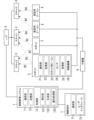
- FIG. 1 is a block diagram of a mobility management system and equipment used with the mobility management system, according to one embodiment.
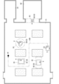
- FIG. 2 is a plan view of a facility where the above movement management system is used.
- FIG. 3 is a sequence diagram showing an example of the operation of the above mobility management system.
- the movement management system 1 (see FIG. 1) of this embodiment controls the movement of the robot 2 in the facility F1 (see FIG. 2).
- the movement management system 1 is capable of communicating with the robot 2.
- the movement management system 1 controls the movement of the robot 2 by communicating with the robot 2.
- "Communicable" in the present disclosure means that signals can be exchanged directly or indirectly via a network, a repeater, or the like using an appropriate communication method such as wired communication or wireless communication.
- “Facilities” in this disclosure include, for example, residences, stores, office buildings, factories, warehouses, commercial complexes, libraries, art museums, museums, amusement facilities, theme parks, parks, airports, railway stations, baseball stadiums, hotels, and Hospitals, etc.
- the "facility” may be a moving object such as a ship or a railway vehicle.
- the "facility” may be an indoor facility or an outdoor facility.
- the movement management system 1 of this embodiment includes a positioning section 131, a generation section 132, and a notification processing section 133.
- the positioning unit 131 determines the position of the robot 2 based on the beacon signal B2 received by the scanner 3 installed in the facility F1.
- the beacon signal B2 is transmitted from the robot beacon 23 mounted on the autonomously moving robot 2.
- the generation unit 132 generates movement guide information.
- the notification processing unit 133 transmits movement guide information to the robot 2.
- the movement guide information includes position information regarding the position of the robot 2 determined by the positioning unit 131, and restriction information regarding the range of the restricted area R1 (see FIG. 2) in which the movement of the robot 2 is restricted within the facility F1. .
- the restricted area R1 can be determined more reliably by the robot 2 than in the case where the restricted area R1 is determined based only on the output of the sensor 24 included in the robot 2. Therefore, the motion of the robot 2 can be more accurately restricted.
- the movement management method of this embodiment includes a positioning step, a generation step, and a notification step.
- the positioning step the position of the robot 2 is determined based on the beacon signal B2 received by the scanner 3 installed in the facility F1.
- the beacon signal B2 is transmitted from the robot beacon 23 mounted on the autonomously moving robot 2.
- movement guide information is generated.
- movement guide information is transmitted to the robot 2.
- the movement guide information includes position information regarding the position of the robot 2 determined in the positioning step, and restriction information regarding the range of the restricted area R1 within the facility F1 in which the movement of the robot 2 is restricted.
- the movement management method can be implemented as a program.
- the program of this embodiment is a program for causing one or more processors of a computer system to execute a movement management method.
- the program may be recorded on a non-transitory recording medium readable by a computer system.
- the movement management system 1 includes, for example, one or more (two in FIG. 1) robots 2, one or more (three in FIG. 1) scanners 3, and one or more (two in FIG. 1) scanners 3. It is used together with a facility beacon 4, a hub 5, a repeater 6, and an information terminal 7.
- the hub 5 relays communication between the mobility management system 1 and the plurality of scanners 3.
- a signal output from the mobility management system 1 is branched at the hub 5 and transmitted to a plurality of scanners 3.
- the hub 5 is, for example, a PoE (Power over Ethernet) hub, and is electrically connected to the plurality of scanners 3 via a LAN (Local Area Network) cable.
- the hub 5 supplies power to the plurality of scanners 3.
- the relay device 6 relays communication between the movement management system 1 and the plurality of robots 2. Further, the repeater 6 relays communication between the movement management system 1 and the plurality of facility beacons 4.
- the repeater 6 is, for example, a WiFi (registered trademark) router.
- the repeater 6 communicates with the plurality of robots 2 and the plurality of facility beacons 4 through wireless communication using radio waves or the like.
- each of the plurality of robots 2 has a robot beacon 23 that transmits a beacon signal B2.
- Each of the plurality of facility beacons 4 transmits a beacon signal B4.
- Beacon signals B2 and B4 are radio signals.
- Each of the plurality of scanners 3 receives the beacon signals B2 and B4, and measures the received signal strength indicator (RSSI) of the received beacon signals B2 and B4.
- RSSI received signal strength indicator
- the mobility management system 1 includes a communication section 11, a storage section 12, and a processing section 13.
- the communication unit 11 includes a communication interface device.
- the communication unit 11 is capable of communicating with a plurality of robots 2, a plurality of scanners 3, and a plurality of facility beacons 4 via a communication interface device.
- the communication unit 11 acquires information on the received signal strength of the beacon signals B2 and B4 and identification information of the source of the beacon signals B2 and B4 from the plurality of scanners 3.
- the storage unit 12 is a storage device configured by a hard disk drive (HDD), solid state drive (SSD), or the like.
- the storage unit 12 stores map information of the facility F1, information regarding the positions of the plurality of scanners 3, and the like.
- the processing unit 13 includes a computer system having one or more processors and memory. At least some of the functions of the processing unit 13 are realized by the processor of the computer system executing a program recorded in the memory of the computer system.
- the program may be recorded in a memory, provided through a telecommunications line such as the Internet, or provided recorded on a non-temporary recording medium such as a memory card.
- the processing unit 13 includes a positioning unit 131, a generation unit 132, and a notification processing unit 133. Note that these merely indicate the functions realized by the processing unit 13, and do not necessarily indicate the actual configuration.
- the positioning unit 131 uses information on the received signal strength of the beacon signals B2 and B4 to determine the positions of the sources of the beacon signals B2 and B4. For example, when the positioning unit 131 determines the position of the robot 2 that is the source of the beacon signal B2, the plurality of scanners 3 measure the received signal strength of the received beacon signal B2. Furthermore, the beacon signal B2 includes identification information of the robot 2 that is the transmission source. Each of the plurality of scanners 3 transmits a first signal including information on the received signal strength of the beacon signal B2, identification information of the transmission source, and identification information of the scanner itself (scanner 3) to the movement management system 1. . The communication unit 11 of the mobility management system 1 receives the first signal.
- the positioning unit 131 determines the distance between the robot 2 as the transmission source and each of the three or more scanners 3 based on the received signal strength measured by three or more of the plurality of scanners 3. . Furthermore, the positioning unit 131 uses the above distance to determine the position of the robot 2 through three-point positioning.
- the positioning unit 131 determines the position of the facility beacon 4 that is the source of the beacon signal B4, the plurality of scanners 3 measure the received signal strength of the received beacon signal B4. Furthermore, the beacon signal B4 includes identification information of the facility beacon 4 that is the transmission source. Each of the plurality of scanners 3 transmits a second signal including information on the received signal strength of the beacon signal B4, identification information of the transmission source, and identification information of its own device (scanner 3) to the movement management system 1. .
- the communication unit 11 of the movement management system 1 receives the second signal.
- the positioning unit 131 determines the distance between the facility beacon 4 as the transmission source and each of the three or more scanners 3 based on the received signal strength measured by three or more scanners 3 among the plurality of scanners 3. seek. Further, the positioning unit 131 uses the above distance to determine the position of the facility beacon 4 through three-point positioning.
- the generation unit 132 generates movement guide information.
- the notification processing unit 133 transmits movement guide information to the robot 2. More specifically, the notification processing unit 133 controls the communication unit 11 to cause the communication unit 11 to transmit movement guide information.
- the movement guide information includes position information regarding the position of the robot 2 determined by the positioning unit 131 and a restricted area R1 (see FIG. 2) in which the movement of the robot 2 is restricted in the facility F1. ) and restriction information regarding the scope of the information.
- the robot 2 Upon receiving the movement guide information, the robot 2 updates the information of the restricted area R1. The robot 2 moves autonomously while imposing specific restrictions on its operation in the restricted area R1.
- the restriction on the operation of the robot 2 in the restricted area R1 includes prohibition of the robot 2 from entering the restricted area R1.
- the robot 2 moves autonomously so as not to invade the restricted area R1.
- the robot 2 stores map information of the facility F1 in advance, and upon acquiring the movement guidance information, extracts the restriction information included in the movement guidance information. After that, the robot 2 links information regarding the range of the restricted area R1 (restriction information) to the map information. As a result, the information on the restricted area R1 stored in the robot 2 is updated.
- Restrictions on the movement of the robot 2 in the restricted area R1 are not limited to prohibiting the robot 2 from entering the restricted area R1.
- the restriction of the motion may include, for example, the robot 2 moving slowly in the restricted area R1.
- the restriction on the movement may include, for example, the robot 2 temporarily stopping before entering the restricted area R1.
- the restriction of the operation may include, for example, the robot 2 issuing a warning by sound or the like before entering the restricted area R1.
- the restriction of the movement may include, when the robot 2 enters the restricted area R1, the robot 2 moves to exit from the restricted area R1.
- the restricted area R1 may include a predetermined area.
- the restricted area R1 may include an area determined according to a user's operation.
- the information terminal 7 that communicates with the mobility management system 1 is equipped with a user interface 72, the restricted area R1 is determined by a user's operation on the user interface 72, and information regarding the determined restricted area R1 is transmitted to the mobile management system 1. may be sent to.
- the movement management system 1 may include the user interface 72 described above.
- the positioning unit 131 may determine the position of the facility beacon 4, and the generation unit 132 may include the area corresponding to the position of the facility beacon 4 determined by the positioning unit 131 in the restricted area R1.
- the area corresponding to the position of the facility beacon 4 includes, for example, the position of the facility beacon 4 and the surrounding positions.
- the positioning unit 131 determines the location of the facility beacon 4 based on the beacon signal B4 transmitted from the facility beacon 4 attached to the target 8 (see FIG. 2) existing in the facility F1 and received by the scanner 3. Find the location.
- the objects 8 are objects 81 to 83 installed in the facility F1 or people 84 present in the facility F1.
- the generation unit 132 may include the area corresponding to the position of the facility beacon 4 determined by the positioning unit 131 in the restricted area R1.
- the object 8 is, for example, an obstacle that obstructs the movement of the robot 2. More specifically, the object 8 is, for example, a fixture such as a shelf or a desk. The object 8 is, for example, an object that does not have a self-propelled function. The object 8 may be an object that can be moved by being carried by a person or a transport device (such as the robot 2 or a forklift).
- the object 8 may be, for example, a sign indicating that trespassing is prohibited.
- examples of the above-mentioned signs include a triangular cone and a signboard.
- the above-mentioned sign may be a sign indicating to a person that trespassing is prohibited, or a sign indicating to the robot 2 that trespassing is prohibited.
- attaching the facility beacon 4 to the object 8 means, for example, that the facility beacon 4 is attached to the object 8.
- the facility beacon 4 does not necessarily need to be fixed to the object 8; for example, the facility beacon 4 may be placed on the object 8.
- the facility beacon 4 does not necessarily have to be in contact with the target 8; for example, the facility beacon 4 may be attached to the ceiling above the location where the target 8 is installed, or the facility beacon 4 may be attached to the area around the target 8. It may be placed on the floor.
- the target 8 may be the ceiling, floor, wall, etc. of the facility F1. That is, the facility beacon 4 may be installed on the floor of a place where the robot 2 is not supposed to enter, or on the ceiling or wall around the floor.
- the attachment of the facility beacon 4 to the target 8 means, for example, that the person carries the facility beacon 4.
- position-range relationship The relationship between the position of the facility beacon 4 and the range of the restricted area R1 (hereinafter referred to as "position-range relationship") may be determined by a user's operation on the user interface 72, for example. Furthermore, the position-range relationship may be determined individually for each facility beacon 4. For example, regarding the facility beacon 4 attached to a certain object 81 (see FIG. 2), a relatively small area around the facility beacon 4 may be set as the restricted area R1. Further, regarding the facility beacon 4 attached to another object 82 (see FIG. 2), a relatively large area around the facility beacon 4 may be set as the restricted area R1.
- the shape of the restricted area R1 may be made different between one target 8 and another target 8.
- a restricted area R1 an area that includes the facility beacon 4 and is long in one direction is defined as a restricted area R1.
- a circular area centered around the facility beacon 4 is defined as a restricted area R1.
- the dimensions of the restricted area R1, such as the width, length, and height, the shape of the restricted area R1, etc. may be determined by the user operating the user interface 72.
- the beacon signal B4 transmitted from the facility beacon 4 includes identification information of the facility beacon 4.
- the movement management system 1 acquires this identification information via the scanner 3. Therefore, the generation unit 132 may acquire attribute information of the target 8 based on this identification information, and determine restrictions on the movement of the robot 2 in the restricted area R1 according to the attribute information.
- the storage unit 12 of the movement management system 1 stores in advance the correspondence between the identification information of the facility beacon 4 and the attribute information of the target 8, and the generation unit 132 stores the correspondence between the identification information of the facility beacon 4 and the attribute information of the target 8. , reads the corresponding attribute information from the storage unit 12.
- the attribute information includes, for example, information regarding whether the target 8 is a person or an object. Further, determining the restriction of operation according to the attribute information includes, for example, varying the position-range relationship depending on the attribute information. In other words, the position-range relationship may be different depending on whether the object 8 is a person or an object. As an example, if the object 8 is a person, the range within a first distance from the person is set as the restricted area R1, and when the object 8 is an object, the range within a second distance from the object is set as the restricted area R1, and the range within a second distance from the object is set as the restricted area R1. The first distance may be longer than the second distance. As another example, the robot 2 may slow down or stop when approaching a person, but may not slow down or stop when approaching an object.
- the attribute information may include information about the person's age, for example.
- the attribute information may include, for example, information regarding at least one of the type and size of the object.
- the movement guide information may include information regarding restrictions for each time period regarding the operation of the robot 2 in the restricted area R1.
- the restrictions on the movement of the robot 2 in the restricted area R1 may vary depending on the time period.
- intrusion may be prohibited in the morning, and intrusion may be permitted in the afternoon.
- entry into a certain restricted area R1 may be prohibited in the morning, and this restricted area R1 may disappear in the afternoon.
- entry may be prohibited in the morning, and entry may be prohibited in the afternoon except when driving slowly.
- the storage unit 12 of the movement management system 1 may store information regarding restrictions for each time period. Then, by referring to this information, the generation unit 132 may generate different travel guide information for each time period.
- the movement guide information may include information regarding restrictions for each purpose of the movement of the robot 2 in the restricted area R1.
- the restrictions on the movement of the robot 2 in the restricted area R1 may differ depending on the purpose of the movement of the robot 2.
- entry for the purpose of inspecting the facility F1 may be permitted, and entry for other purposes may be prohibited.
- entry for the purpose of inspecting the facility F1 may be permitted, and entry for other purposes may be permitted only when driving slowly.
- the storage unit 12 of the movement management system 1 may store information regarding restrictions for each purpose of movement in association with the identification information of each robot 2. Then, by referring to this information, the generation unit 132 may generate different movement guide information for each purpose of the operation of each robot 2. Further, information regarding the purpose of the movement may be transmitted from the robot 2 to the movement management system 1. Alternatively, the purpose of each robot 2's operation may be determined by a user's operation on the user interface 72.
- the robot 2 includes a communication section 21, a storage section 22, a robot beacon 23, a sensor 24, a processing section 25, and a movement mechanism 26.
- the communication unit 21 includes a communication interface device.
- the communication unit 21 is capable of communicating with the mobility management system 1 via a communication interface device.
- the storage unit 22 is a storage device configured by a hard disk drive (HDD), solid state drive (SSD), or the like.
- the storage unit 22 stores identification information of its own machine (robot 2), map information of the facility F1, and the like.
- the robot beacon 23 transmits a beacon signal B2.
- the sensor 24 acquires information regarding the movement of the robot 2.
- the information regarding the movement of the robot 2 includes, for example, information regarding the detection of obstacles.
- the sensor 24 includes, for example, a camera, and the camera photographs the surroundings of the robot 2.
- the processing unit 25 includes a computer system having one or more processors and memory.
- the processing unit 25 performs overall control of the robot 2.
- the processing unit 25 refers to the movement guidance information notified from the movement management system 1 and determines a movement route.
- the processing unit 25 controls the operation of the moving mechanism 26 to move the robot 2 along the above-mentioned moving route.
- the processing unit 25 analyzes an image taken by the camera of the sensor 24 to detect an obstacle.
- the processing unit 25 moves the robot 2 so as to avoid the obstacle detected by the processing unit 25 and the restricted area R1 notified from the movement management system 1.
- the moving mechanism 26 is a driving part for moving the robot 2.
- the moving mechanism 26 includes, for example, wheels and a motor.
- the robot 2 moves as the motor rotates the wheels.
- the plurality of scanners 3 are installed, for example, on the ceiling of the facility F1. Each scanner 3 receives the beacon signal B2 transmitted from the robot 2 and the beacon signal B4 transmitted from the facility beacon 4, and measures the received signal strength. Further, each scanner 3 transmits the received signal strength, the identification information of the source included in the beacon signals B2 and B4, and the identification information of its own device (scanner 3) to the movement management system 1.
- Facility Beacon A plurality of facility beacons 4 are used in the facility F1. As an example, in FIG. 2, one facility beacon 4 is attached to object 81, another facility beacon 4 is attached to object 82, and another facility beacon 4 is attached to object 83. Further, another facility beacon 4 is carried by a person 84.
- Each of the plurality of facility beacons 4 transmits a beacon signal B4.
- the facility beacon 4 may be, for example, a dedicated terminal having only the function of transmitting the beacon signal B4, a mobile phone such as a smartphone, a wearable terminal, or the like.
- the information terminal 7 includes a communication section 71 and a user interface 72.
- the communication unit 71 includes a communication interface device.
- the communication unit 71 is capable of communicating with the mobility management system 1 via a communication interface device.
- the user interface 72 accepts user operations.
- the user interface 72 includes, for example, at least one of a button, a mouse, a touch pad, a touch panel, and a touch panel display.
- the restricted area R1 is determined by the user's operation on the user interface 72, and information regarding the determined restricted area R1 is transmitted to the mobility management system 1 by the communication unit 71.
- the robot 2 transmits a beacon signal B2 (step ST1).
- a plurality of facility beacons 4 (only one is shown in FIG. 3) transmit a beacon signal B4 (step ST2).
- the robot 2 and the plurality of facility beacons 4 transmit beacon signals B2 and B4 at predetermined time intervals.
- a plurality of scanners 3 receives the beacon signals B2 and B4 and measures the received signal strength (RSSI) (step ST3). Furthermore, each scanner 3 receives signals (a first signal and a second signal) that include the received signal strength, the identification information of the transmission source included in the beacon signals B2 and B4, and the identification information of its own device (scanner 3). is transmitted to the movement management system 1 (step ST4). Based on the first signal and the second signal, the positioning unit 131 of the movement management system 1 determines the position of each of the robot 2 and the plurality of facility beacons 4 (step ST5).
- RSSI received signal strength
- the generation unit 132 determines the restricted area R1 based on the position of each of the plurality of facility beacons 4 determined by the positioning unit 131 (step ST6). More specifically, the generation unit 132 includes a position corresponding to the position of each facility beacon 4 in the restricted area R1.
- the restricted area R1 may further include a predetermined area, an area determined according to a user's operation on the user interface 72, and the like.
- the notification processing unit 133 transmits movement guide information to the robot 2 (step ST7).
- the movement guide information includes position information regarding the position of the robot 2 determined by the positioning section 131. Furthermore, the movement guide information includes restriction information regarding the range of restricted area R1.
- the robot 2 receives movement guidance information.
- the processing unit 25 of the robot 2 determines a movement route based on the movement guide information (step ST8).
- the robot 2 moves along the movement route (step ST9).
- FIG. 2 shows an example of the travel route 100 determined by the processing unit 25. More specifically, the processing unit 25 creates a travel route that avoids the restricted area R1 and reaches the destination G1.
- the robot 2 is not necessarily unable to pass through that passage. Whether or not it is impossible to pass through the passage is determined according to the dimensions of the restricted area R1 corresponding to the object 8, etc. In FIG. 2, a road width that the robot 2 can pass is secured beside the restricted area R1 corresponding to the object 81 (target 8), so the robot 2 creates a movement route that passes beside the object 81. do.
- the map information of the facility F1 is stored in the storage unit 22 of the robot 2 in advance.
- the map information may be transmitted from the movement management system 1 to the robot 2.
- the map information includes, for example, three-dimensional model data such as BIM (Building Information Modeling) data of the facility F1. Therefore, the map information includes information indicating areas where the robot 2 cannot run, such as walls, pillars, and steps of the facility F1.
- the robot 2 creates a movement route so as to avoid not only the restricted area R1 but also areas where it cannot travel. That is, the robot 2 creates a movement route by referring to the map information of the facility F1, the position information of its own machine (robot 2) extracted from the movement guide information, and the restriction information regarding the range of the restriction area R1. .
- the robot 2 and the plurality of facility beacons 4 transmit beacon signals B2 and B4 at predetermined time intervals. As a result, steps ST1 to ST9 are repeated. Therefore, the movement management system 1 updates the restricted area R1 and the position information of the robot 2 at predetermined time intervals (for example, every second). Furthermore, the robot 2 updates its movement route at predetermined time intervals (for example, every second). Thereby, the movement route can be updated according to the movement of the robot 2. In addition, as the object 8 (person 84 and objects 81 to 83) to which the facility beacon 4 is attached moves, the restricted area R1 also moves, so the robot 2 is moved according to the current position of the object 8. can be controlled.
- the robot 2 may move to avoid obstacles detected by the sensor 24 in addition to avoiding the restricted area R1.
- the robot 2 can avoid the obstacle if the location where the obstacle is installed is set to the restricted area R1.
- the robot 2 You can avoid restricted areas.
- the number of robots 2 is one, but there may be a plurality of robots 2. If any one of the plurality of robots 2 is defined as a first robot, and any robot other than the first robot among the plurality of robots 2 is defined as a second robot, the generation unit 132 converts the area corresponding to the position of the second robot into a second robot. It may be included in the restriction area R1 for restricting the movement of one robot.
- the area corresponding to the position of the second robot includes, for example, the position of the second robot and the surrounding positions.
- the facility beacon 4 is attached to the object 83 present at the entrance of the room 92, and the corresponding restricted area R1 is set to block the entrance of the room 92. As a result, the robot 2 is prohibited from entering the room 92. On the other hand, since the facility beacon 4 is not installed at the entrance of the room 91, the robot 2 enters the room 91 and cleans it. In this way, by installing the object 83 to which the facility beacon 4 is attached at an appropriate location, the movement of the robot 2 can be managed without requiring complicated settings. Furthermore, by moving the object 83 together with the facility beacon 4, the manner in which movement of the robot 2 is managed can be changed.
- the robot 2 determines its own movement route.
- the generation unit 132 of the movement management system 1 may determine the movement route.
- the notification processing unit 133 transmits to the robot 2 movement guide information including route instruction information that instructs the movement route of the robot 2.
- the robot 2 extracts a movement route from the route instruction information and moves along the movement route.
- the movement guide information sent from the movement management system 1 to the robot 2 may include instructions for the movement of the robot 2.
- the movement management system 1 may instruct the robot 2 to change its traveling direction using movement guide information.
- the restricted area R1 includes a first restricted area and a second restricted area, and the restrictions on the movement of the robot 2 may be different between the first restricted area and the second restricted area. For example, if a second restricted area is set around the first restricted area, and the robot 2 is prohibited from entering the first restricted area, and the robot 2 enters the second restricted area, the robot 2 is restricted. You may move to leave area R1.
- Two devices that communicate via wired communication in the embodiment may instead communicate via wireless communication. Conversely, two devices that communicate via wireless communication in the embodiment may alternatively communicate via wired communication.
- the positioning unit 131 determines the positions of the sources of the beacon signals B2 and B4 based on the received signal strengths of the beacon signals B2 and B4.
- the method by which the positioning unit 131 determines the position of the transmission source is not limited to three-point positioning. For example, when the beacon signal B2 transmitted from the robot 2 is received by a specific scanner 3, the positioning unit 131 specifies that the position of the robot 2 is within the area surrounding the specific scanner 3. can.
- the positioning unit 131 may find the positions of the sources of the beacon signals B2 and B4 based on the phases of the beacon signals B2 and B4 instead of the received signal strengths of the beacon signals B2 and B4.
- the sensor 24 is not limited to a configuration in which an obstacle is photographed using a camera.
- the sensor 24 may include, for example, an ultrasonic sensor, an infrared sensor, or a LiDAR (Light Detection And Ranging), and may detect an obstacle.
- an ultrasonic sensor for example, an ultrasonic sensor, an infrared sensor, or a LiDAR (Light Detection And Ranging), and may detect an obstacle.
- LiDAR Light Detection And Ranging
- the movement management system 1 communicates with the robot 2 through a communication path different from the communication path through which it communicates with the scanner 3.
- the scanner 3 may relay communication between the movement management system 1 and the robot 2.
- the number of robots 2 and scanners 3 is not limited to the number shown in the embodiment, and may be one or more.
- the number of facility beacons 4 is not limited to the number shown in the embodiment, and may be one. Furthermore, the facility beacon 4 is not an essential component.
- the hub 5, repeater 6, and information terminal 7 are not essential components.
- the execution entity of the mobility management system 1 or the mobility management method in the present disclosure includes a computer system.
- a computer system mainly consists of a processor and a memory as hardware. At least a part of the function as an execution entity of the mobility management system 1 or the mobility management method according to the present disclosure is realized by the processor executing the program recorded in the memory of the computer system.
- the program may be pre-recorded in the memory of the computer system, may be provided through a telecommunications line, or may be recorded on a non-transitory storage medium readable by the computer system, such as a memory card, optical disc, hard disk drive, etc. may be provided.
- a processor in a computer system is comprised of one or more electronic circuits including semiconductor integrated circuits (ICs) or large scale integrated circuits (LSIs).
- the integrated circuits such as IC or LSI referred to herein have different names depending on the degree of integration, and include integrated circuits called system LSI, VLSI (Very Large Scale Integration), or ULSI (Ultra Large Scale Integration).
- FPGAs Field-Programmable Gate Arrays
- logic devices that can reconfigure the connections inside the LSI or reconfigure the circuit sections inside the LSI, may also be used as processors. I can do it.
- the plurality of electronic circuits may be integrated into one chip, or may be provided in a distributed manner over a plurality of chips.
- a plurality of chips may be integrated into one device, or may be distributed and provided in a plurality of devices.
- the computer system herein includes a microcontroller having one or more processors and one or more memories. Therefore, the microcontroller is also composed of one or more electronic circuits including semiconductor integrated circuits or large-scale integrated circuits.
- the mobility management system 1 it is not an essential configuration for the mobility management system 1 that multiple functions in the mobility management system 1 are integrated into one device, and multiple components of the mobility management system 1 are distributed among multiple devices. may be provided. Furthermore, at least some of the functions of the movement management system 1, for example, at least some of the functions of the generation unit 132, may be realized by a server, a cloud (cloud computing), or the like.
- the movement management system 1 may further include at least one robot 2.
- a device hereinafter referred to as a basic device including the communication section 11, storage section 12, and processing section 13 of the movement management system 1 is provided separately from the robot 2. That is, the plurality of components of the mobility management system 1 are distributed and provided in a plurality of devices.
- the robot 2 includes a sensor 24 that recognizes obstacles.
- the movement management system 1 may further include at least one scanner 3.
- the basic device of the movement management system 1 is provided separately from the scanner 3.
- the movement management system (1) includes a positioning section (131), a generation section (132), and a notification processing section (133).
- the positioning unit (131) determines the position of the robot (2) based on the beacon signal (B2) received by the scanner (3) installed in the facility (F1).
- the beacon signal (B2) is transmitted from a robot beacon (23) mounted on an autonomously moving robot (2).
- a generation unit (132) generates movement guide information.
- the notification processing unit (133) transmits movement guide information to the robot (2).
- the movement guide information includes position information regarding the position of the robot (2) determined by the positioning unit (131) and restrictions regarding the range of the restricted area (R1) in the facility (F1) where the movement of the robot (2) is restricted. Contains information and.
- the robot (2) can more reliably determine the restricted area (R1) than when determining the restricted area (R1) based only on the output of the sensor (24) included in the robot (2). is required. Therefore, the movement of the robot (2) can be more accurately restricted.
- the positioning unit (131) uses The location of the facility beacon (4) is determined based on the beacon signal (B4) that is transmitted and received by the scanner (3).
- the object (8) is an object installed in the facility (F1) or a person present in the facility (F1).
- the generation unit (132) includes the area corresponding to the position of the facility beacon (4) determined by the positioning unit (131) in the restricted area (R1).
- the positioning unit (131) determines the position of the target (8), and the generating unit (132) determines the position of the target (8). can be newly set.
- the beacon signal (B4) transmitted from the facility beacon (4) includes identification information of the facility beacon (4).
- the generation unit (132) acquires attribute information of the target (8) based on the identification information, and determines a restriction on the movement of the robot (2) in the restricted area (R1) according to the attribute information.
- the robot (2) can be made to perform actions according to the attribute information.
- the restriction on the movement of the robot (2) in the restricted area (R1) is limited to the restricted area (R1). This includes prohibition of robots (2) from entering.
- the movement guidance information is a time period related to the movement of the robot (2) in the restricted area (R1). Contains information about limits per.
- restrictions on the operation of the robot (2) can be set for each time period.
- the movement guidance information is about the movement of the robot (2) in the restricted area (R1). Contains information about limits by purpose.
- restrictions on the movement of the robot (2) can be set for each purpose of the movement of the robot (2).
- the movement guide information includes route instruction information that instructs the movement route of the robot (2).
- the movement management system (1) according to the eighth aspect further includes a robot (2) in any one of the first to seventh aspects.
- the robot (2) includes a sensor (24) that recognizes obstacles.
- the robot (2) can autonomously move based on the output of the sensor (24) and the movement guidance information obtained from the notification processing section (133).
- the movement management system (1) according to the ninth aspect further includes a scanner (3) in any one of the first to eighth aspects.
- Configurations other than the first aspect are not essential to the mobility management system (1) and can be omitted as appropriate.
- the movement management method includes a positioning step, a generation step, and a notification step.
- the positioning step the position of the robot (2) is determined based on the beacon signal (B2) received by the scanner (3) installed in the facility (F1).
- the beacon signal (B2) is transmitted from a robot beacon (23) mounted on an autonomously moving robot (2).
- movement guide information is generated.
- movement guide information is transmitted to the robot (2).
- the movement guide information includes position information regarding the position of the robot (2) obtained in the positioning step, restriction information regarding the range of a restricted area (R1) in the facility (F1) where the movement of the robot (2) is restricted, including.
- the movement of the robot (2) can be more accurately restricted.
- the program according to the eleventh aspect is a program for causing one or more processors of the computer system to execute the movement management method according to the tenth aspect.
- the movement of the robot (2) can be more accurately restricted.
- various configurations (including modifications) of the movement management system (1) according to the embodiment can be implemented in a movement management method, a (computer) program, or a non-temporary recording medium on which the program is recorded. It is possible to convert
Landscapes
- Engineering & Computer Science (AREA)
- Aviation & Aerospace Engineering (AREA)
- Radar, Positioning & Navigation (AREA)
- Remote Sensing (AREA)
- Physics & Mathematics (AREA)
- General Physics & Mathematics (AREA)
- Automation & Control Theory (AREA)
- Control Of Position, Course, Altitude, Or Attitude Of Moving Bodies (AREA)
Priority Applications (1)
| Application Number | Priority Date | Filing Date | Title |
|---|---|---|---|
| JP2024516179A JP7796371B2 (ja) | 2022-04-20 | 2023-04-05 | 移動管理システム、移動管理方法及びプログラム |
Applications Claiming Priority (2)
| Application Number | Priority Date | Filing Date | Title |
|---|---|---|---|
| JP2022-069674 | 2022-04-20 | ||
| JP2022069674 | 2022-04-20 |
Publications (1)
| Publication Number | Publication Date |
|---|---|
| WO2023204025A1 true WO2023204025A1 (ja) | 2023-10-26 |
Family
ID=88419803
Family Applications (1)
| Application Number | Title | Priority Date | Filing Date |
|---|---|---|---|
| PCT/JP2023/014037 Ceased WO2023204025A1 (ja) | 2022-04-20 | 2023-04-05 | 移動管理システム、移動管理方法及びプログラム |
Country Status (2)
| Country | Link |
|---|---|
| JP (1) | JP7796371B2 (https=) |
| WO (1) | WO2023204025A1 (https=) |
Citations (6)
| Publication number | Priority date | Publication date | Assignee | Title |
|---|---|---|---|---|
| JP2019135579A (ja) * | 2018-02-05 | 2019-08-15 | 本田技研工業株式会社 | 移動体制御システム、移動体及び移動体制御方法 |
| WO2019240208A1 (ja) * | 2018-06-13 | 2019-12-19 | Groove X株式会社 | ロボットおよびその制御方法、ならびにプログラム |
| JP2020034531A (ja) * | 2018-08-31 | 2020-03-05 | 株式会社Where | 案内システム |
| JP2021117903A (ja) * | 2020-01-29 | 2021-08-10 | パナソニックIpマネジメント株式会社 | 情報処理システムおよび情報処理方法 |
| JP2022023273A (ja) * | 2020-07-27 | 2022-02-08 | 啓太 瀧澤 | 誘導情報生成プログラム |
| JP2022030366A (ja) * | 2020-08-07 | 2022-02-18 | サトーホールディングス株式会社 | 情報処理装置、プログラム、情報処理方法 |
-
2023
- 2023-04-05 WO PCT/JP2023/014037 patent/WO2023204025A1/ja not_active Ceased
- 2023-04-05 JP JP2024516179A patent/JP7796371B2/ja active Active
Patent Citations (6)
| Publication number | Priority date | Publication date | Assignee | Title |
|---|---|---|---|---|
| JP2019135579A (ja) * | 2018-02-05 | 2019-08-15 | 本田技研工業株式会社 | 移動体制御システム、移動体及び移動体制御方法 |
| WO2019240208A1 (ja) * | 2018-06-13 | 2019-12-19 | Groove X株式会社 | ロボットおよびその制御方法、ならびにプログラム |
| JP2020034531A (ja) * | 2018-08-31 | 2020-03-05 | 株式会社Where | 案内システム |
| JP2021117903A (ja) * | 2020-01-29 | 2021-08-10 | パナソニックIpマネジメント株式会社 | 情報処理システムおよび情報処理方法 |
| JP2022023273A (ja) * | 2020-07-27 | 2022-02-08 | 啓太 瀧澤 | 誘導情報生成プログラム |
| JP2022030366A (ja) * | 2020-08-07 | 2022-02-18 | サトーホールディングス株式会社 | 情報処理装置、プログラム、情報処理方法 |
Also Published As
| Publication number | Publication date |
|---|---|
| JP7796371B2 (ja) | 2026-01-09 |
| JPWO2023204025A1 (https=) | 2023-10-26 |
Similar Documents
| Publication | Publication Date | Title |
|---|---|---|
| CN108829095B (zh) | 地理围栏设置方法及限制机器人运动的方法 | |
| KR102951170B1 (ko) | 로봇 친화형 건물 | |
| CN109998429B (zh) | 用于情境感知的移动清洁机器人人工智能 | |
| Ahmetovic et al. | NavCog: a navigational cognitive assistant for the blind | |
| US10657691B2 (en) | System and method of automatic room segmentation for two-dimensional floorplan annotation | |
| JP6158150B2 (ja) | 屋内尤度ヒートマップ | |
| JP2024020582A (ja) | ロボットおよびその制御方法、ならびにプログラム | |
| JP6833111B1 (ja) | 表示制御装置、表示システム、及び、表示制御方法 | |
| KR20200015348A (ko) | 속성 블록의 경계를 설정하는 이동 로봇 | |
| JP2017152964A (ja) | 監視装置および監視装置用プログラム | |
| US20220288778A1 (en) | Methods of controlling a mobile robot device to follow or guide a person | |
| JPWO2019054205A1 (ja) | 移動ロボットシステム | |
| US20250109963A1 (en) | Robot-friendly buildings, and map generation methods and systems for robot operation | |
| JP7796371B2 (ja) | 移動管理システム、移動管理方法及びプログラム | |
| JP2021087137A (ja) | 測定システム、測定方法及びプログラム | |
| KR20250143725A (ko) | 로봇 친화형 건물, 건물을 주행하는 로봇 제어 방법 및 시스템 | |
| Roy et al. | Route planning for automatic indoor driving of smart cars | |
| Kang et al. | Automated parking lot management system using embedded robot type smart car based on wireless sensors | |
| KR102642128B1 (ko) | 자율주행 로봇, 운영 서버, 및 광고 시스템 | |
| US11127170B1 (en) | Multi-level premise mapping with security camera drone | |
| WO2025022819A1 (ja) | 入退管理システム、入退管理方法及びプログラム | |
| CN112739619A (zh) | 使用无人车辆定位部署在天花板或地板空间或其它不便空间或设备中的资产 | |
| WO2024257698A1 (ja) | ロボットシステム、判断システム、判断方法及びプログラム | |
| KR102913732B1 (ko) | 로봇 친화형 건물, 건물을 주행하는 로봇 제어 방법 및 시스템 | |
| JP7706995B2 (ja) | 検出システム、検出方法、および情報処理装置 |
Legal Events
| Date | Code | Title | Description |
|---|---|---|---|
| 121 | Ep: the epo has been informed by wipo that ep was designated in this application |
Ref document number: 23791676 Country of ref document: EP Kind code of ref document: A1 |
|
| WWE | Wipo information: entry into national phase |
Ref document number: 2024516179 Country of ref document: JP |
|
| NENP | Non-entry into the national phase |
Ref country code: DE |
|
| WWE | Wipo information: entry into national phase |
Ref document number: 11202406863S Country of ref document: SG |
|
| 122 | Ep: pct application non-entry in european phase |
Ref document number: 23791676 Country of ref document: EP Kind code of ref document: A1 |