WO2023203742A1 - 冷凍サイクル装置 - Google Patents
冷凍サイクル装置 Download PDFInfo
- Publication number
- WO2023203742A1 WO2023203742A1 PCT/JP2022/018505 JP2022018505W WO2023203742A1 WO 2023203742 A1 WO2023203742 A1 WO 2023203742A1 JP 2022018505 W JP2022018505 W JP 2022018505W WO 2023203742 A1 WO2023203742 A1 WO 2023203742A1
- Authority
- WO
- WIPO (PCT)
- Prior art keywords
- refrigerant
- refrigerant pipe
- sound absorbing
- end surface
- damping material
- Prior art date
Links
- 238000005057 refrigeration Methods 0.000 title claims abstract description 38
- 239000003507 refrigerant Substances 0.000 claims abstract description 153
- 239000000463 material Substances 0.000 claims abstract description 152
- 238000013016 damping Methods 0.000 claims abstract description 80
- 239000011358 absorbing material Substances 0.000 claims abstract description 70
- 230000002093 peripheral effect Effects 0.000 claims description 23
- 230000001419 dependent effect Effects 0.000 claims 1
- 239000011810 insulating material Substances 0.000 description 14
- 230000000694 effects Effects 0.000 description 12
- 239000012774 insulation material Substances 0.000 description 8
- 238000004804 winding Methods 0.000 description 8
- 238000010586 diagram Methods 0.000 description 4
- 230000004048 modification Effects 0.000 description 4
- 238000012986 modification Methods 0.000 description 4
- XLYOFNOQVPJJNP-UHFFFAOYSA-N water Substances O XLYOFNOQVPJJNP-UHFFFAOYSA-N 0.000 description 4
- 238000010521 absorption reaction Methods 0.000 description 3
- CURLTUGMZLYLDI-UHFFFAOYSA-N Carbon dioxide Chemical compound O=C=O CURLTUGMZLYLDI-UHFFFAOYSA-N 0.000 description 2
- 230000006835 compression Effects 0.000 description 2
- 238000007906 compression Methods 0.000 description 2
- 229920001971 elastomer Polymers 0.000 description 2
- 230000005484 gravity Effects 0.000 description 2
- 238000005259 measurement Methods 0.000 description 2
- 239000000203 mixture Substances 0.000 description 2
- 239000011148 porous material Substances 0.000 description 2
- 239000012267 brine Substances 0.000 description 1
- 229920005549 butyl rubber Polymers 0.000 description 1
- 229910002092 carbon dioxide Inorganic materials 0.000 description 1
- 239000001569 carbon dioxide Substances 0.000 description 1
- 238000001816 cooling Methods 0.000 description 1
- 230000002542 deteriorative effect Effects 0.000 description 1
- 239000011491 glass wool Substances 0.000 description 1
- 238000005338 heat storage Methods 0.000 description 1
- 238000010438 heat treatment Methods 0.000 description 1
- 230000001771 impaired effect Effects 0.000 description 1
- 229920005989 resin Polymers 0.000 description 1
- 239000011347 resin Substances 0.000 description 1
- HPALAKNZSZLMCH-UHFFFAOYSA-M sodium;chloride;hydrate Chemical compound O.[Na+].[Cl-] HPALAKNZSZLMCH-UHFFFAOYSA-M 0.000 description 1
- 238000010257 thawing Methods 0.000 description 1
Images


Classifications
-
- F—MECHANICAL ENGINEERING; LIGHTING; HEATING; WEAPONS; BLASTING
- F16—ENGINEERING ELEMENTS AND UNITS; GENERAL MEASURES FOR PRODUCING AND MAINTAINING EFFECTIVE FUNCTIONING OF MACHINES OR INSTALLATIONS; THERMAL INSULATION IN GENERAL
- F16L—PIPES; JOINTS OR FITTINGS FOR PIPES; SUPPORTS FOR PIPES, CABLES OR PROTECTIVE TUBING; MEANS FOR THERMAL INSULATION IN GENERAL
- F16L55/00—Devices or appurtenances for use in, or in connection with, pipes or pipe systems
- F16L55/02—Energy absorbers; Noise absorbers
- F16L55/033—Noise absorbers
-
- F—MECHANICAL ENGINEERING; LIGHTING; HEATING; WEAPONS; BLASTING
- F25—REFRIGERATION OR COOLING; COMBINED HEATING AND REFRIGERATION SYSTEMS; HEAT PUMP SYSTEMS; MANUFACTURE OR STORAGE OF ICE; LIQUEFACTION SOLIDIFICATION OF GASES
- F25B—REFRIGERATION MACHINES, PLANTS OR SYSTEMS; COMBINED HEATING AND REFRIGERATION SYSTEMS; HEAT PUMP SYSTEMS
- F25B41/00—Fluid-circulation arrangements
- F25B41/40—Fluid line arrangements
Definitions
- the present disclosure relates to a refrigeration cycle device that includes refrigerant piping covered with a soundproofing material.
- Patent Document 1 discloses an air conditioner in which a compressor that generates a lot of noise is provided with soundproofing measures.
- the noise of the compressor is reduced by wrapping the first noise reduction member made of a sound absorbing material and the second noise reduction member made of a sound absorbing material and a sound insulating material around the compressor. There is.
- Patent Document 1 the noise generated by the compressor is reduced, but the noise generated by the refrigerant piping is not reduced. Therefore, there is a problem in that the sound of the refrigerant flowing through the refrigerant piping, the vibrations generated by the refrigerant flowing through the refrigerant piping, and the noise generated due to the state of the refrigerant flowing through the refrigerant piping cannot be reduced.
- the present disclosure has been made to solve the above-mentioned problems, and aims to provide a refrigeration cycle device that can reduce noise generated in refrigerant piping.
- a refrigeration cycle device is provided between a compressor, a heat source side heat exchanger, a load side heat exchanger, and a compressor, a heat source side heat exchanger, and a load side heat exchanger, and a refrigerant is provided between the compressor, the heat source side heat exchanger, and the load side heat exchanger.
- refrigerant piping forming a circulating refrigerant circuit, at least a part of the outer peripheral surface of the refrigerant piping is covered with a soundproofing material over the entire circumferential direction, and the soundproofing material is provided with a soundproofing material that surrounds the outer peripheral surface of at least a part of the refrigerant piping. It has a damping material provided so as to cover the entire circumferential direction, and a sound absorbing material provided so as to cover the outer peripheral surface of the damping material throughout the circumferential direction.
- the outer circumferential surface of at least a portion of the refrigerant pipe is covered with the soundproofing material over the entire circumferential direction.
- the soundproof material includes a vibration damping material and a sound absorbing material. Since the vibration damping material suppresses the vibration of the refrigerant pipe, it is possible to reduce the sound radiated from the surface of the refrigerant pipe due to the vibration. Further, since the sound emitted from the refrigerant pipe is absorbed by the sound absorbing material, the sound generated in the refrigerant pipe is less likely to be radiated to the outside of the sound absorbing material, thereby reducing noise. Therefore, noise generated in the refrigerant piping can be reduced.
- FIG. 1 is an external perspective view of a heat source device of a refrigeration cycle device according to an embodiment.
- FIG. It is a schematic diagram explaining the composition of refrigerant piping covered with the soundproofing material concerning an embodiment.
- FIG. 4 is a schematic cross-sectional view schematically showing a refrigerant pipe covered with the soundproofing material of FIG. 3.
- FIG. 4 is a graph showing a noise level ratio comparing the noise levels before and after providing the soundproofing material of FIG. 3.
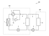
- FIG. 1 is a circuit diagram showing the configuration of a refrigeration cycle device 300 according to an embodiment.
- the refrigeration cycle device 300 includes a heat source device 100 and a utilization device 200.
- a vapor compression type refrigeration cycle operation using a refrigerant is performed in the heat source device 100.
- the utilization device 200 is, for example, a water heater, an air handling unit, an indoor unit of an air conditioner, or the like.
- a configuration in which refrigeration cycle device 300 is an indirect expansion type air conditioner will be described. More specifically, the refrigeration cycle device 300 will be described in a case where the heat source device 100 is an outdoor unit installed outdoors and the usage device 200 is an indoor unit of an air conditioner that uses a heat medium.
- the heat source device 100 includes a compressor 1, a heat source side heat exchanger 3, an air blower 7, an expansion valve 4, a load side heat exchanger 2, a four-way valve 5, and refrigerant piping. 6 is provided.
- the heat source device 100 connects a compressor 1, a four-way valve 5, a heat source side heat exchanger 3, an expansion valve 4, and a load side heat exchanger 2 in an annular manner via a refrigerant pipe 6, so that a refrigerant such as carbon dioxide Constitutes a circulating refrigerant circuit.
- the refrigerant piping 6 includes a first refrigerant piping section 6a through which a cold, low-pressure gas refrigerant sucked into the compressor 1 flows.
- the compressor 1 sucks and compresses a cold temperature and low pressure gas refrigerant flowing through the first refrigerant piping section 6a, and discharges the gas refrigerant in a high temperature and high pressure state.
- a four-way valve 5 is provided on the discharge side of the compressor 1.
- the four-way valve 5 can switch the direction in which the refrigerant flows. However, the four-way valve 5 may not be provided and the flow of the refrigerant may be constant.
- the four-way valve 5 can be switched to the flow path shown by the broken line in FIG. 1 during cooling operation and defrosting operation, and can be switched to the flow path shown by the solid line in FIG. 1 during heating operation.
- the load-side heat exchanger 2 exchanges heat between the refrigerant flowing through the refrigerant pipe 6 and the heat medium flowing through the usage-side pipe 9, which will be described later.
- the expansion valve 4 reduces the pressure of the high-pressure refrigerant and adjusts the pressure and flow rate of the refrigerant.
- the heat source side heat exchanger 3 exchanges heat between the refrigerant passing through the heat source side heat exchanger 3 and air.
- the blower 7 sends air to the heat source side heat exchanger 3. In the heat source side heat exchanger 3, the refrigerant exchanges heat with outdoor air sent by the blower 7, for example.
- the utilization device 200 has a utilization side heat exchanger 10.
- the utilization device 200 and the heat source device 100 are connected by a utilization side piping 9. More specifically, the load-side heat exchanger 2 and the usage-side heat exchanger 10 are connected by the usage-side piping 9.
- the utilization device 200 connects the load-side heat exchanger 2, the utilization-side heat exchanger 10, and the pump 8 in an annular manner via the utilization-side piping 9, and constitutes a heat medium circuit in which a heat medium such as water or brine circulates. do.
- the heat medium flowing through the user-side piping 9 exchanges heat with the refrigerant flowing through the refrigerant piping 6 in the load-side heat exchanger 2 .
- the pump 8 pressurizes the heat medium and circulates it within the heat medium circuit.
- the user-side heat exchanger 10 exchanges heat between the heat medium and the air in the air-conditioned space.
- the refrigeration cycle device 300 may be a direct expansion type air conditioner.
- the load-side heat exchanger 2 is not provided in the refrigeration cycle device 300, and the usage-side heat exchanger 10 functions as a load-side heat exchanger.
- the compressor 1, the heat source side heat exchanger 3, and the user side heat exchanger 10 functioning as a load side heat exchanger are connected in an annular manner by refrigerant piping. Therefore, a refrigerant circuit in which refrigerant circulates through the refrigerant pipes is formed, and the refrigeration cycle device 300, which is an air conditioner, performs vapor compression refrigeration cycle operation.
- the refrigeration cycle device 300 is not limited to an air conditioner.
- the refrigeration cycle device 300 may be another device such as a water heater, a chiller, or a heat storage device.
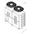
- FIG. 2 is an external perspective view of the heat source device 100 of the refrigeration cycle device 300 according to the embodiment.
- the refrigeration cycle device 300 is an indirect expansion type air conditioner
- the heat source device 100 is an outdoor unit of the air conditioner.
- the arrows shown in FIG. 2 indicate the front-rear direction of the heat source device 100, and the arrows indicate the direction from the back to the front.
- the heat source device 100 has a housing 100a. Inside the casing 100a, the compressor 1, the heat source side heat exchanger 3, the blower 7, the expansion valve 4, and the load side are included in the part surrounded by the broken line showing the heat source device 100 in FIG.
- a heat exchanger 2, a four-way valve 5, a refrigerant pipe 6, and a portion of a user-side pipe 9 are accommodated (not shown).
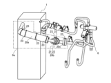
- FIG. 3 is a schematic diagram illustrating the configuration of the refrigerant pipe 6 covered with the soundproofing material 20 according to the embodiment.
- FIG. 3 shows the compressor 1 and the first refrigerant piping section 6a housed in the housing 100a of the heat source device 100.
- the first refrigerant piping section 6a which is a part of the refrigerant piping 6, is a portion surrounded by a broken line in FIG.
- FIG. 4 is a schematic cross-sectional view schematically showing the refrigerant pipe 6 covered with the soundproofing material 20 of FIG. 3.
- FIG. 4 shows a cross section of the first refrigerant pipe section 6a, which is a part of the refrigerant pipe 6 covered with the soundproofing material 20, perpendicular to the central axis.
- the soundproofing material 20 is provided so as to cover the entire outer peripheral surface of the refrigerant pipe 6 in the circumferential direction.
- the soundproof material 20 is formed from a damping material 21 and a sound absorbing material 22.
- the damping material 21 is provided on the outer peripheral surface of the refrigerant pipe 6 over the entire circumferential direction.
- the sound absorbing material 22 is provided on the outer peripheral surface of the vibration damping material 21 over the entire circumferential direction.
- the soundproofing material 20 can be provided at multiple locations on the refrigerant pipe 6. The portion of the refrigerant pipe 6 where the soundproofing material 20 is provided and the number of soundproofing materials 20 provided are not limited.
- soundproofing material 20 is provided in three parts of the first refrigerant piping section 6a. That is, the soundproofing material 20 includes a first soundproofing material 20a, a second soundproofing material 20b, and a third soundproofing material 20c.
- the soundproofing material 20 includes a first soundproofing material 20a, a second soundproofing material 20b, and a third soundproofing material 20c.
- soundproofing material 20 it shall include both the singular and plural.
- the range in which the plurality of soundproofing materials 20 cover the first refrigerant piping section 6a and the number of soundproofing materials 20 are not limited to the illustrated example.
- one soundproofing material 20 may cover from the outer peripheral surface of the refrigerant pipe 6 covered with the first soundproofing material 20a in FIG. 3 to the outer peripheral surface of the refrigerant piping 6 covered with the third soundproofing material 20c.
- the outer circumferential surface of the refrigerant pipe 6 between the first sound insulating material 20a and the second sound insulating material 20b and the outer circumferential surface of the refrigerant pipe 6 between the second sound insulating material 20b and the third sound insulating material 20c are respectively It may be covered with a No.
- the first soundproofing material 20a to the third soundproofing material 20c may have different sizes. That is, when a plurality of soundproofing materials 20 are provided, the sizes of each soundproofing material 20 do not need to be the same.
- the damping material 21 is a member that suppresses the vibration and sound pressure of the object by converting the vibration of the object into thermal energy and dissipating it into the air.
- the damping material 21 of this embodiment which is attached to the refrigerant pipe 6 which is tubular and has a bent portion, is made of an elastically deformable material such as rigid resin or rubber so that it can be easily attached to the refrigerant pipe 6. is desirable.
- the damping material 21 is made of a vibration damping material such as butyl rubber with a specific gravity of about 2.6 or rubber with a specific gravity of about 2.4, for example.
- the damping material 21 suppresses vibrations that occur when the refrigerant flows through the refrigerant pipe 6. Therefore, the sound radiated from the surface of the refrigerant pipe 6 due to vibration can be reduced.
- the damping material 21 is composed of a sheet-shaped member.
- a sheet-shaped damping material 21 is wound around the outer peripheral surface of the refrigerant pipe 6 in the circumferential direction CR.
- the damping material 21 has a first end surface 21 a and a second end surface 21 b that extend along the central axis of the refrigerant pipe 6 .
- the first end surface 21a and the second end surface 21b are end surfaces of the sheet-shaped damping material 21.
- the damping material 21 is provided on the outer peripheral surface of the refrigerant pipe 6 so that the first end surface 21a and the second end surface 21b are in surface contact with each other. That is, in the example shown in FIG.
- the damping material 21 is wound around the refrigerant pipe 6 such that the starting part and the ending part of the sheet-shaped damping material 21 do not overlap.
- the first end surface 21a and the second end surface 21b are in surface contact.
- the refrigerant pipe 6 is placed by overlapping the winding start part and the winding end part of the vibration damping material 21. It may be provided on the outer peripheral surface of the.
- the sound absorbing material 22 is a member that converts the energy of sound waves transmitted in the air into thermal energy and absorbs it.
- the sound absorbing material 22 is made of, for example, a porous material such as felt or glass wool. Since the sound radiated from the refrigerant pipe 6 is absorbed by the sound absorbing material 22, the sound generated in the refrigerant pipe 6 is less likely to be radiated to the outside of the sound absorbing material 22, and the noise is reduced.
- the sound absorbing material 22 is composed of a sheet-shaped member.
- a sheet-shaped sound absorbing material 22 is wound around the outer peripheral surface of the damping material 21 in the circumferential direction CR.
- the sound absorbing material 22 has a first end surface 22 a and a second end surface 22 b that extend along the central axis of the refrigerant pipe 6 .
- the first end surface 22a and the second end surface 22b are end surfaces of the sheet-shaped sound absorbing material 22.
- the sound absorbing material 22 is provided on the outer circumferential surface of the damping material 21 so that the first end surface 22a and the second end surface 22b are in surface contact with each other. That is, in the example of FIG.
- the sound absorbing material 22 is wound around the damping material 21 so that the winding start part and the winding end part of the sheet-shaped sound absorbing material 22 do not overlap, and The first end surface 22a and the second end surface 22b are in surface contact. Note that if it is difficult to provide the first end surface 22a and the second end surface 22b of the sound absorbing material 22 in contact with each other, the outer periphery of the damping material 21 may be formed by overlapping the winding start part and the winding end part of the sound absorbing material 22. It may be provided on the surface.
- a sound absorbing material 22 is attached to the outer circumferential surface of the vibration damping material 21, so that the outer circumferential surface of the sound insulating material 20 is formed by the sound absorbing material 22. By doing so, the function of the sound absorbing material 22 can be exerted without impairing its function.
- the materials of the damping material 21 and the sound absorbing material 22 that form the sound insulation material 20 may be changed depending on the part of the refrigerant pipe 6 where the sound insulation material 20 is provided.
- the temperature of the refrigerant pipe 6 on the discharge side of the compressor 1 becomes high.
- the refrigerant pipe 6 on the discharge side of the compressor 1 is provided with a damping material 21 made of a material that can withstand even when the outer peripheral surface of the refrigerant pipe 6 becomes high temperature, and a damping material 21 that is made of a material that can withstand even when the outer peripheral surface of the refrigerant pipe 6 becomes high temperature.
- a sound insulating material 20 having a sound absorbing material 22 made of a material that can withstand even the harshest conditions may be changed depending on the part of the refrigerant pipe 6 where the sound insulation material 20 is provided.
- the temperature of the refrigerant pipe 6 on the discharge side of the compressor 1 becomes high.
- the refrigerant pipe 6 on the discharge side of the compressor 1
- FIG. 4 in the circumferential direction CR of the refrigerant pipe 6, the position where the first end surface 21a and the second end surface 21b of the vibration damping material 21 are in contact, and the position where the first end surface 22a and the second end surface 22b of the sound absorbing material 22 are in contact with each other are shown.
- the contact position is misaligned.
- the outer peripheral surface of the refrigerant pipe 6 is covered with at least a damping material 21 or a sound absorbing material 22. Therefore, since the function of either the damping material 21 or the sound absorbing material 22 is maintained, it is possible to suppress a decrease in the noise reduction effect of the sound insulating material 20.
- the position where the first end face 21a and the second end face 21b of the vibration damping material 21 contact and the position where the first end face 22a and the second end face 22b of the sound absorbing material 22 contact are in the circumferential direction of the refrigerant pipe 6. It may be at the same position in CR.
- the soundproofing material 20 is fixed by a fixture 23.
- the fixture 23 is string-shaped and is provided so as to surround the outer peripheral surface of the sound absorbing material 22 in the circumferential direction CR so that the sound insulating material 20 is fixed to the refrigerant pipe 6.
- the fixture 23 may cause the soundproof material 20 to come off from the refrigerant pipe 6, create a gap between the refrigerant pipe 6 and the damping material 21, or create a gap between the vibration damper 21 and the sound absorbing material 22. This can be prevented. Since no gap is created between the refrigerant pipe 6 and the soundproof material 20, the noise reduction effect of the soundproof material 20 is improved.
- the shape of the fixture 23 is not limited to a string shape. Further, it is not necessary to surround and fix the soundproofing material 20 in the circumferential direction CR, and for example, a fixture 23 that fixes the winding start part and the winding end part of the sound absorbing material 22 outside the vibration damping material 21 may be used. It may be provided. Note that, in order to prevent the sound absorption performance of the sound absorbing material 22 from deteriorating, it is desirable that the fixture 23 has a small portion that presses down the sound absorbing material 22. Further, the number of fixtures 23 and the positions at which they are fixed may be selected depending on the size of the soundproofing material 20. In other words, the number of fixtures 23 used to secure one soundproofing material 20 is not limited. Further, the position where the soundproofing material 20 is fixed with the fixture 23 is not limited either.
- FIG. 5 is a graph showing a noise level ratio comparing the noise levels before and after providing the soundproofing material 20 of FIG. 3.
- the noise level was acquired by a microphone for noise measurement installed at a predetermined distance from the back of the casing 100a of the heat source device 100 shown in FIG.
- the noise level ratio is a value derived from the noise levels measured before and after installing the soundproofing material 20 in FIG. is the proportion of the noise level. More specifically, the noise level ratio is a value obtained by dividing the noise level before providing the soundproofing material 20 by the noise level after providing the soundproofing material 20. Therefore, when the noise level ratio exceeds 100.0%, it can be determined that the soundproofing material 20 has a noise reduction effect.
- the vertical axis shows the noise level ratio (%)
- the horizontal axis shows the frequency (Hz) after 1/3 octave analysis on a logarithmic scale.
- the noise level ratio shows a value close to 110.0% in the range from 3000 Hz to 10000 Hz. Therefore, it can be determined that the effect of noise reduction by the soundproof material 20 is large in the frequency range from 3000 Hz to 10000 Hz.
- the total noise level before installing the soundproofing material 20 which was obtained by a microphone for noise measurement installed at a predetermined distance on the back of the housing 100a, was 66.2 dB (A), and when the soundproofing material 20 was installed The total noise level after the test was 65.1 dB(A). Since the total noise level after providing the soundproofing material 20 is reduced by 1.1 dB (A), it can be said that the noise generated in the refrigerant pipe 6 is reduced by the soundproofing material 20. Note that the total noise level is a value derived based on the noise level at each frequency from 80 Hz to 10,000 Hz.
- the refrigeration cycle device 300 includes the compressor 1, the heat source side heat exchanger 3, the load side heat exchanger 2, the compressor 1 and the heat source side heat exchanger 3.
- a refrigerant pipe 6 is provided between the load-side heat exchanger and forms a refrigerant circuit in which refrigerant circulates, and the outer peripheral surface of at least a portion of the refrigerant pipe 6 is covered with a soundproofing material 20 over the entire circumferential direction.
- the soundproofing material 20 includes a damping material 21 provided so as to cover the entire circumferential surface of at least a portion of the refrigerant pipe 6, and a damping material 21 provided so as to cover the entire circumferential surface of the vibration damping material 21. It has a sound absorbing material 22.
- the load-side heat exchanger 2 is an example of a load-side heat exchanger
- the usage-side heat exchanger 10 may be provided as a load-side heat exchanger.
- the outer circumferential surface of at least a portion of the refrigerant pipe 6 is covered in the entire circumferential direction with the sound insulating material 20 having the damping material 21 and the sound absorbing material 22. Since vibration of the refrigerant pipe 6 is suppressed by the damping material 21, it is possible to reduce sound radiated from the surface of the refrigerant pipe 6 due to the vibration. Further, since the sound emitted from the refrigerant pipe 6 is absorbed by the sound absorbing material 22, the sound generated in the refrigerant pipe 6 is less likely to be radiated to the outside of the sound absorbing material 22, and noise is reduced. Therefore, the noise generated in the refrigerant pipe 6 can be reduced by the soundproofing material 20.
- the outer peripheral surface of at least a portion of the refrigerant pipe 6 is in contact with the damping material 21 over the entire circumferential direction, and the outer peripheral surface of the vibration damping material 21 is made of sound absorbing material over the entire circumferential direction. I am in contact with 22.
- the sound insulating material 20 including the damping material 21 and the sound absorbing material 22 is stacked on the outer circumferential surface of the refrigerant pipe 6 without any gaps. Therefore, the noise reduction effect of the soundproofing material 20 is improved.
- the refrigeration cycle device 300 further includes a housing 100a that houses the compressor 1 and the heat source side heat exchanger 3, and the refrigerant pipe 6 is connected to the casing 100a through which the refrigerant flowing into the compressor 1 flows.
- a housing 100a that houses the compressor 1 and the heat source side heat exchanger 3, and the refrigerant pipe 6 is connected to the casing 100a through which the refrigerant flowing into the compressor 1 flows.
- 1 refrigerant piping section 6a, the first refrigerant piping section 6a is provided inside the housing 100a, and at least a part of the refrigerant piping 6 covered with the soundproofing material 20 is connected to the first refrigerant piping section 6a. It is.
- the noise generated in the first refrigerant piping section 6a located inside the housing 100a can be reduced. Therefore, the noise generated from the housing 100a can be reduced, and the influence of the noise generated from the housing 100a on the surroundings can be reduced.
- the damping material 21 has a sheet shape having a first end surface 21a and a second end surface 21b extending along the central axis of the refrigerant pipe 6, and the damping material The first end surface 21a of the damping material 21 and the second end surface 21b of the damping material 21 are in surface contact with each other.
- the first end surface 21a and the second end surface 21b of the vibration damping material 21 are provided on the outer circumferential surface of the refrigerant pipe 6 without overlapping, with the first end surface 21a and the second end surface 21b in surface contact. Therefore, the damping material 21 can cover the entire outer peripheral surface of the refrigerant pipe 6 in the circumferential direction without any gaps. Further, since the outer circumferential surface of the damping material 21 is in a flat state, it becomes possible to cover the outer circumferential surface of the damping material 21 with the sound absorbing material 22 without any gaps in the entire circumferential direction. As a result, there is no gap between the refrigerant pipe 6, the damping material 21, and the sound absorbing material 22, and the noise reduction effect of the sound insulating material 20 is improved.
- the sound absorbing material 22 has a sheet shape having a first end surface 22a and a second end surface 22b extending along the central axis of the refrigerant pipe 6.
- the first end surface 22a and the second end surface 22b of the sound absorbing material 22 are in surface contact.
- the first end surface 22a and the second end surface 22b of the sound absorbing material 22 are provided on the outer circumferential surface of the vibration damping material 21 without overlapping, with the first end surface 22a and the second end surface 22b in surface contact. Since the sound absorbing material 22 can cover the entire outer peripheral surface of the damping material 21 in the circumferential direction without any gaps, the noise reduction effect of the sound insulating material 20 is improved.
- the position where the first end surface 21a and the second end surface 21b of the damping material 21 are in contact with each other in the circumferential direction CR of the refrigerant pipe 6 is the position of the sound absorbing material 22. This is different from the position where the first end surface 22a and the second end surface 22b are in contact. For this reason, if a gap occurs at the same time in the surface where the first end surface 21a and the second end surface 21b of the damping material 21 contact and the surface where the first end surface 22a and the second end surface 22b of the sound absorbing material 22 contact. However, since the function of either the vibration damping material 21 or the sound absorbing material 22 is maintained, a decrease in the noise reduction effect of the sound insulating material 20 can be suppressed.
- the sheet-shaped damping material 21 may have a tube shape instead of a sheet shape.
- the damping material 21 may have a seamless cylindrical shape that extends along the central axis of the refrigerant pipe 6. According to this configuration, the damping material 21 does not separate from the refrigerant pipe 6. Therefore, the effect of suppressing vibration of the refrigerant pipe 6 by the damping material 21 is stably maintained. Further, since the damping material 21 has no seams, the outer circumferential surface of the refrigerant pipe 6 can be reliably covered in the entire circumferential direction without any gaps. Therefore, the vibration suppressing effect of the damping material 21 is improved.
- the sheet-shaped sound absorbing material 22 has been described above.
- the sound absorbing material 22 may have a tube shape instead of a sheet shape.
- the sound absorbing material 22 may have a seamless cylindrical shape extending along the central axis of the refrigerant pipe 6. According to this configuration, the sound absorbing material 22 does not separate from the refrigerant pipe 6. Therefore, the effect of the sound absorbing material 22 absorbing the sound radiated from the refrigerant pipe 6 is stably maintained.
- the sound absorbing material 22 has no seams, the outer circumferential surface of the vibration damping material 21 can be reliably covered over the entire circumferential direction without any gaps. Therefore, the sound absorbing effect of the sound absorbing material 22 is improved.
Landscapes
- Engineering & Computer Science (AREA)
- General Engineering & Computer Science (AREA)
- Mechanical Engineering (AREA)
- Physics & Mathematics (AREA)
- Thermal Sciences (AREA)
- Compressor (AREA)
Abstract
冷凍サイクル装置は、圧縮機と、熱源側熱交換器と、負荷側熱交換器と、圧縮機と熱源側熱交換器と負荷側熱交換器との間に設けられ、冷媒が循環する冷媒回路を形成する冷媒配管とを備え、冷媒配管の少なくとも一部の外周面が周方向全体にわたって防音材で覆われており、防音材は、冷媒配管の少なくとも一部の外周面を周方向全体にわたって覆うように設けられる制振材と、制振材の外周面を周方向全体にわたって覆うように設けられる吸音材とを有する。
Description
本開示は、防音材に覆われた冷媒配管を備えた冷凍サイクル装置に関するものである。
空気調和機、チラー、及び給湯器などの冷凍サイクル装置では、発生する騒音を低減する防音対策を備えたものがある。例えば、特許文献1には、大きな騒音を発生する圧縮機に防音対策が施されている空気調和機が開示されている。この空気調和機では、吸音材で形成された第1騒音低減部材と、吸音材と遮音材で形成された第2騒音低減部材を、圧縮機に巻き付けることで、圧縮機の騒音が低減されている。
特許文献1では、圧縮機で発生する騒音は低減されるが、冷媒配管で発生する騒音は低減されない。このため、冷媒が冷媒配管を流れる通過音並びに冷媒が冷媒配管を流れることで発生する振動及び冷媒配管を流れる冷媒の状態が原因で発生する音が低減されないという課題があった。
本開示は、上述のような課題を解決するためになされたものであり、冷媒配管で発生する騒音を低減することができる冷凍サイクル装置を提供することを目的とする。
本開示に係る冷凍サイクル装置は、圧縮機と、熱源側熱交換器と、負荷側熱交換器と、圧縮機と熱源側熱交換器と負荷側熱交換器との間に設けられ、冷媒が循環する冷媒回路を形成する冷媒配管とを備え、冷媒配管の少なくとも一部の外周面が周方向全体にわたって防音材で覆われており、防音材は、冷媒配管の少なくとも一部の外周面を周方向全体にわたって覆うように設けられる制振材と、制振材の外周面を周方向全体にわたって覆うように設けられる吸音材とを有する。
本開示によれば、冷媒配管の少なくとも一部の外周面は、防音材により周方向全体にわたって覆われている。防音材は、制振材と吸音材とを有する。制振材により冷媒配管の振動が抑制されるので、振動に起因して冷媒配管の表面から放射される音を減少させることができる。また、吸音材により冷媒配管から放射された音が吸音されるので、冷媒配管で発生した音が吸音材の外側へ放射されにくくなり、騒音が低減される。このため、冷媒配管で発生する騒音を低減することができる。
以下、本開示に係る冷凍サイクル装置の実施の形態及び変形例について図面を参照して説明する。本開示は、以下の実施の形態及び変形例に限定されるものではなく、本開示の主旨を逸脱しない範囲で種々に変形することが可能である。また、本開示は、以下の実施の形態及び変形例に示す構成のうち、組み合わせ可能な構成のあらゆる組み合わせを含むものである。また、各図において、同一の符号を付したものは、同一の又はこれに相当するものであり、これは明細書の全文において共通している。なお、各図面では、各構成部材の相対的な寸法関係又は形状等が実際のものとは異なる場合がある。
実施の形態.
図1は、実施の形態に係る冷凍サイクル装置300の構成を示す回路図である。冷凍サイクル装置300は、熱源装置100と利用装置200とを備えている。熱源装置100では、冷媒を用いた蒸気圧縮式の冷凍サイクル運転が行われる。利用装置200は、例えば、給湯器、エアハンドリングユニット、及び空気調和機の室内機などである。本実施の形態では、冷凍サイクル装置300が間接膨張式の空気調和機である構成について説明する。より詳しくは、熱源装置100が室外に設置される室外機であり、利用装置200が熱媒体を利用する空気調和機の室内機である場合の冷凍サイクル装置300について説明する。
図1は、実施の形態に係る冷凍サイクル装置300の構成を示す回路図である。冷凍サイクル装置300は、熱源装置100と利用装置200とを備えている。熱源装置100では、冷媒を用いた蒸気圧縮式の冷凍サイクル運転が行われる。利用装置200は、例えば、給湯器、エアハンドリングユニット、及び空気調和機の室内機などである。本実施の形態では、冷凍サイクル装置300が間接膨張式の空気調和機である構成について説明する。より詳しくは、熱源装置100が室外に設置される室外機であり、利用装置200が熱媒体を利用する空気調和機の室内機である場合の冷凍サイクル装置300について説明する。
図1に示すように、熱源装置100には、圧縮機1と、熱源側熱交換器3と、送風機7と、膨張弁4と、負荷側熱交換器2と、四方弁5と、冷媒配管6とが設けられている。熱源装置100は、圧縮機1、四方弁5、熱源側熱交換器3、膨張弁4、及び負荷側熱交換器2を、冷媒配管6を介して環状に接続し、二酸化炭素などの冷媒が循環する冷媒回路を構成する。冷媒配管6には、圧縮機1に吸入される冷温及び低圧のガス冷媒が流れる第1冷媒配管部6aが含まれる。
圧縮機1は、第1冷媒配管部6aを流れる冷温及び低圧のガス冷媒を吸引して圧縮し、高温及び高圧のガス冷媒の状態にして吐出する。圧縮機1の吐出側には、四方弁5が設けられる。四方弁5により冷媒が流れる方向を切り替えることができる。しかし、四方弁5を設けずに、冷媒の流れを一定としてもよい。四方弁5は、例えば、冷房運転時及び霜取り運転時に図1の破線の流路に切り替え、暖房運転時に図1の実線の流路に切り替えることができる。負荷側熱交換器2は、冷媒配管6を流れる冷媒と、後述する利用側配管9を流れる熱媒体とを熱交換させる。膨張弁4は、高圧の冷媒を減圧させ、冷媒の圧力及び流量を調整する。熱源側熱交換器3は、熱源側熱交換器3を通過する冷媒と、空気とを熱交換させる。送風機7は、熱源側熱交換器3に空気を送る。熱源側熱交換器3では、冷媒が、例えば送風機7によって送られた屋外の空気と熱交換する。
利用装置200は、利用側熱交換器10を有する。利用装置200と熱源装置100とは利用側配管9により接続されている。より詳しくは、負荷側熱交換器2と利用側熱交換器10とが利用側配管9により接続されている。利用装置200は、負荷側熱交換器2、利用側熱交換器10、ポンプ8を、利用側配管9を介して環状に接続し、水又はブラインなどの熱媒体が循環する熱媒体回路を構成する。利用側配管9を流れる熱媒体は、負荷側熱交換器2で、冷媒配管6を流れる冷媒と熱交換する。ポンプ8は、熱媒体を加圧して熱媒体回路内を循環させる。利用側熱交換器10は、熱媒体と空調対象空間の空気とを熱交換させる。
また、図示しないが、冷凍サイクル装置300が直接膨張式の空気調和機であってもよい。この場合、冷凍サイクル装置300に、負荷側熱交換器2が設けられず、利用側熱交換器10が負荷側熱交換器として機能する。圧縮機1と、熱源側熱交換器3と、負荷側熱交換器として機能する利用側熱交換器10とが冷媒配管で環状に接続される。したがって、冷媒配管を冷媒が循環する冷媒回路が形成され、空気調和機である冷凍サイクル装置300は、蒸気圧縮方式の冷凍サイクル運転を行う。
なお上記では、冷凍サイクル装置300の構成例として空気調和機の説明をした。しかし、冷凍サイクル装置300は、空気調和機に限定されない。例えば、冷凍サイクル装置300は、給湯器、チラー、及び蓄熱装置など他の装置であってもよい。
図2は、実施の形態に係る冷凍サイクル装置300の熱源装置100の外観斜視図である。図1で説明したように、冷凍サイクル装置300は間接膨張式の空気調和機であり、熱源装置100は、空気調和機の室外機である。図2に示す矢印は、熱源装置100の前後方向を示し、矢印により背面から前面方向を示すこととする。熱源装置100は、筐体100aを有する。筐体100aの内部には、図1で熱源装置100を示す破線で囲まれた部分に含まれる、圧縮機1と、熱源側熱交換器3と、送風機7と、膨張弁4と、負荷側熱交換器2と、四方弁5と、冷媒配管6と、利用側配管9の一部とが収容されている(図示せず)。
図3及び図4を参照して、冷媒配管6の少なくとも一部に設けられる防音材20について説明する。図3は、実施の形態に係る防音材20で覆われた冷媒配管6の構成を説明する概略図である。図3では、熱源装置100の筐体100aに収容された、圧縮機1及び第1冷媒配管部6aを示している。冷媒配管6の一部である第1冷媒配管部6aは、図3において破線で囲まれた部分である。図4は、図3の防音材20で覆われた冷媒配管6を模式的に示す概略断面図である。図4では、防音材20で覆われた冷媒配管6の一部である第1冷媒配管部6aの、中心軸線に垂直な断面を示している。
図3及び図4に示すように、防音材20は、冷媒配管6の外周面を周方向全体にわたって覆うように設けられる。防音材20は、制振材21及び吸音材22から形成される。制振材21は、冷媒配管6の外周面に周方向全体にわたって設けられる。吸音材22は、制振材21の外周面に周方向全体にわたって設けられる。防音材20は、冷媒配管6の複数の場所に設けることができる。防音材20が設けられる冷媒配管6の部分及び設けられる防音材20の数は限定されない。
図3では、防音材20が、第1冷媒配管部6aの3つの部分に設けられている。すなわち、防音材20が、第1防音材20aと第2防音材20bと第3防音材20cとを含んでいる。以下の説明において、第1防音材20aと第2防音材20bと第3防音材20cとを特に区別する必要がない場合には、単に「防音材20」と適宜称する。また、「防音材20」と称した場合には、単数又は複数の両方を含むものとする。また、複数の防音材20が第1冷媒配管部6aを覆う範囲及び防音材20の数は、図示の例に限定されない。例えば、図3の第1防音材20aで覆われた冷媒配管6の外周面から第3防音材20cで覆われた冷媒配管6の外周面までを1つの防音材20で覆ってもよい。また、第1防音材20aと第2防音材20bとの間の冷媒配管6の外周面、及び第2防音材20bと第3防音材20cとの間の冷媒配管6の外周面をそれぞれ、第4防音材及び第5防音材で覆ってもよい。また、図3に示すように、第1防音材20a~第3防音材20cのそれぞれの大きさが異なっていてもよい。すなわち、防音材20が複数設けられる場合、各防音材20の大きさが同一である必要はない。
制振材21は、対象の振動を熱エネルギーに変えて空気中に発散させることで、対象の振動及び音圧を抑制する部材である。管状で曲がり部分を有する冷媒配管6に取り付けられる本実施の形態の制振材21は、冷媒配管6へ容易に取り付けられるように、弾性変形可能な剛性樹脂又はゴム等の材料で構成されているのが望ましい。制振材21は、例えば、比重が2.6程度のブチルゴム又は比重が2.4程度のゴムなどの防振材料からなる。制振材21により、冷媒が冷媒配管6を流れることで発生する振動が抑制される。したがって、振動に起因して冷媒配管6の表面から放射される音を減少させることができる。
制振材21は、本実施の形態では、シート形状の部材で構成されている。シート形状の制振材21が、冷媒配管6の外周面に、周方向CRに巻かれている。制振材21は、冷媒配管6の中心軸線に沿って延びる第1端面21aと第2端面21bとを有する。第1端面21a及び第2端面21bは、シート形状の制振材21の端面である。図4に示すように、冷媒配管6の外周面において、制振材21は、第1端面21aと第2端面21bとが面接触した状態で設けられる。すなわち図4の例では、制振材21が、シート形状の制振材21の巻き始めの部分と巻き終わりの部分とが重ならないように、冷媒配管6に巻かれており、制振材21の第1端面21aと第2端面21bとが面接触している。なお、制振材21の第1端面21aと第2端面21bとを面接触して設けることが難しい場合は、制振材21の巻き始めの部分と巻き終わりの部分とを重ねて冷媒配管6の外周面に設けてもよい。
吸音材22は、空気中に伝わる音波のエネルギーを熱エネルギーに変換して吸収する部材である。吸音材22は、例えば、フェルト又はグラスウールなどの多孔質材料からなる。吸音材22により冷媒配管6から放射された音が吸音されるので、冷媒配管6で発生した音が吸音材22の外側へ放射されにくくなり、騒音が低減される。
吸音材22は、本実施の形態では、シート形状の部材で構成されている。シート形状の吸音材22が、制振材21の外周面に、周方向CRに巻かれている。吸音材22は、冷媒配管6の中心軸線に沿って延びる第1端面22aと第2端面22bとを有する。第1端面22a及び第2端面22bは、シート形状の吸音材22の端面である。図4に示すように、制振材21の外周面において、吸音材22は、第1端面22aと第2端面22bとが面接触した状態で設けられる。すなわち図4の例では、吸音材22が、シート形状の吸音材22の巻き始めの部分と巻き終わりの部分とが重ならないように、制振材21に巻かれており、吸音材22の第1端面22aと第2端面22bとが面接触している。なお、吸音材22の第1端面22aと第2端面22bとを接触して設けることが難しい場合は、吸音材22の巻き始めの部分と巻き終わりの部分とを重ねて制振材21の外周面に設けてもよい。
吸音材22が押さえつけられると多孔性が損なわれ、吸音材22の吸音性能が低下するおそれがある。このため、仮に、防音材20の外周面に、制振材21等の他の部材を重ねると、重ねられた他の部材に抑えられて、多孔質材料で構成された吸音材22の空隙がつぶれて吸音性能が低下しうる。そこで本実施の形態では、制振材21の外周面に吸音材22を取り付けて、防音材20の外周面が吸音材22により形成される構成としている。このようにすることで、吸音材22の機能を損なうことなく発揮させることができる。
防音材20を形成する、制振材21及び吸音材22の材料は、防音材20が設けられる冷媒配管6の部分に応じて変更してもよい。圧縮機1の吐出側の冷媒配管6の温度は高くなる。このため、圧縮機1の吐出側の冷媒配管6には、冷媒配管6の外周面が高温になっても耐え得る材料からなる制振材21と、制振材21の外周面が高温になっても耐え得る材料からなる吸音材22とを有する防音材20を用いてもよい。
また、図4では、冷媒配管6の周方向CRにおいて、制振材21の第1端面21aと第2端面21bとが接触する位置と、吸音材22の第1端面22aと第2端面22bとが接触する位置とがずれている。このようにすることで、冷凍サイクル装置300の運転時の振動により、制振材21の第1端面21aと第2端面21bとの接触及び吸音材22の第1端面22aと第2端面22bとの接触が同時に解かれた場合でも、冷媒配管6の外周面が露出しない。すなわち、制振材21の第1端面21aと第2端面21bとが接触する面及び吸音材22の第1端面22aと第2端面22bとが接触する面、それぞれに隙間が同時に生じた場合でも、冷媒配管6の外周面は、少なくとも制振材21又は吸音材22で覆われることになる。したがって、制振材21又は吸音材22のどちらか一方の機能が維持されるので、防音材20の騒音低減効果の低下を抑制することができる。なお、制振材21の第1端面21aと第2端面21bとが接触する位置と、吸音材22の第1端面22aと第2端面22bとが接触する位置とが、冷媒配管6の周方向CRにおいて同じ位置であってもよい。
図3に示すように、防音材20は、固定具23により固定される。固定具23は紐状であり、防音材20が冷媒配管6に固定されるように、吸音材22の外周面を周方向CRに取り囲むように設けられる。固定具23により、防音材20が冷媒配管6から外れたり、冷媒配管6と制振材21との間に隙間が生じたり、制振材21と吸音材22との間に隙間が生じたりすることを防ぐことができる。冷媒配管6と防音材20との間に隙間が生じないことで、防音材20の騒音低減効果が向上する。
固定具23の形状は紐状に限定されない。また、防音材20を周方向CRに取り囲んで固定する必要はなく、例えば、制振材21よりも外側にある吸音材22の巻き始めの部分と巻き終わりの部分とを固定する固定具23を設けてもよい。なお、吸音材22の吸音性能が低下しないように、吸音材22を押さえつける部分が少ない固定具23が望ましい。また固定具23の数及び固定する位置は、防音材20の大きさに応じて選択すればよい。言い換えると、1つの防音材20を固定するために利用する固定具23の数は限定されない。また、防音材20を固定具23で固定する位置も限定されない。
図5は、図3の防音材20を設ける前後の騒音レベルを比較した騒音レベル比率を示したグラフである。騒音レベルは、図2に示す熱源装置100の筐体100aの背面に所定の距離を空けて設置した騒音測定用のマイクにより取得した。騒音レベル比率は、図3の防音材20を設ける前後で測定して得た騒音レベルから導き出した数値であり、防音材20を設けた状態での騒音レベルに対する、防音材20を設けない状態での騒音レベルの割合である。より詳しくは、騒音レベル比率は、防音材20を設ける前の騒音レベルを、防音材20を設けた後の騒音レベルで除した値である。したがって、騒音レベル比率が100.0%を超える場合に、防音材20による騒音低減効果があったと判断できる。
図5のグラフでは、縦軸は騒音レベル比率(%)を示し、横軸は1/3オクターブ分析後の周波数(Hz)を対数目盛で示す。図5では、3000Hzから10000Hzまでの範囲で、騒音レベル比率が110.0%に近い値を示している。したがって、周波数が3000Hzから10000Hzまでの範囲において、防音材20による騒音低減の効果が大きいと判断できる。
また、筐体100aの背面に所定の距離を空けて設置した騒音測定用のマイクにより取得した防音材20を設ける前の合計騒音レベルは、66.2dB(A)であり、防音材20を設けた後の合計騒音レベルは、65.1dB(A)であった。防音材20を設けた後の合計騒音レベルが1.1dB(A)減少していることから、冷媒配管6で発生する騒音が、防音材20により低減されているといえる。なお、合計騒音レベルは80Hz~10000Hzまでの各周波数での騒音レベルに基づいて導き出した値である。
以上説明したように、本実施の形態に係る冷凍サイクル装置300は、圧縮機1と、熱源側熱交換器3と、負荷側熱交換器2と、圧縮機1と熱源側熱交換器3と負荷側熱交換器との間に設けられ、冷媒が循環する冷媒回路を形成する冷媒配管6とを備え、冷媒配管6の少なくとも一部の外周面が周方向全体にわたって防音材20で覆われており、防音材20は、冷媒配管6の少なくとも一部の外周面を周方向全体にわたって覆うように設けられる制振材21と、制振材21の外周面を周方向全体にわたって覆うように設けられる吸音材22とを有する。ここで、負荷側熱交換器2は、負荷側熱交換器の一例であり、利用側熱交換器10を負荷側熱交換器として設けてもよい。
この構成によれば、冷媒配管6の少なくとも一部の外周面が、制振材21と吸音材22とを有する防音材20により周方向全体にわたって覆われている。制振材21により冷媒配管6の振動が抑制されるので、振動に起因して冷媒配管6の表面から放射される音を減少させることができる。また、吸音材22により冷媒配管6から放射された音が吸音されるので、冷媒配管6で発生した音が吸音材22の外側へ放射されにくくなり、騒音が低減される。したがって、防音材20により冷媒配管6で発生する騒音を低減することができる。
また、本実施の形態における冷凍サイクル装置300において、冷媒配管6の少なくとも一部の外周面は周方向全体にわたって制振材21と接触し、制振材21の外周面は周方向全体にわたって吸音材22と接触している。この構成によれば、冷媒配管6の外周面に、制振材21と吸音材22とを有する防音材20が隙間なく重ねられる。このため、防音材20の騒音低減効果が向上する。
また、本実施の形態に係る冷凍サイクル装置300は、圧縮機1と熱源側熱交換器3とを収容する筐体100aをさらに備え、冷媒配管6は、圧縮機1に流入する冷媒が流れる第1冷媒配管部6aを含み、第1冷媒配管部6aは、筐体100aの内部に設けられており、防音材20に覆われている冷媒配管6の少なくとも一部は、第1冷媒配管部6aである。
この構成によれば、筐体100aの内部に位置する第1冷媒配管部6aで発生する騒音を低減することができる。このため、筐体100aから発生する騒音を低減することができ、筐体100aで発生する騒音が周囲へ与える影響を小さくすることができる。
また、本実施の形態に係る冷凍サイクル装置300において、制振材21は、冷媒配管6の中心軸線に沿って延びる第1端面21aと第2端面21bとを有するシート形状であり、制振材21の第1端面21aと制振材21の第2端面21bとは面接触している。
この構成によれば、制振材21の第1端面21aと第2端面21bとが面接触した状態で、重なることなく冷媒配管6の外周面に設けられる。このため、制振材21が冷媒配管6の外周面を隙間なく周方向全体にわたって覆うことができる。また、制振材21の外周面が平らな状態となるので、制振材21の外周面を周方向全体わたって隙間なく吸音材22で覆うことが可能になる。結果として、冷媒配管6と制振材21と吸音材22との間に隙間がない状態となり、防音材20の騒音低減効果が向上する。
また、本実施の形態に係る冷凍サイクル装置300において、吸音材22は、冷媒配管6の中心軸線に沿って延びる第1端面22aと第2端面22bとを有するシート形状であり、吸音材22の第1端面22aと吸音材22の第2端面22bとは面接触している。
この構成によれば、吸音材22の第1端面22aと第2端面22bとが面接触した状態で、重なることなく制振材21の外周面に設けられる。吸音材22が制振材21の外周面を隙間なく周方向全体にわたって覆うことができるので、防音材20の騒音低減効果が向上する。
また、本実施の形態に係る冷凍サイクル装置300において、冷媒配管6の周方向CRにおいて、制振材21の第1端面21aと第2端面21bとが接触している位置は、吸音材22の第1端面22aと第2端面22bとが接触している位置と異なる。このため、制振材21の第1端面21aと第2端面21bとが接触する面及び吸音材22の第1端面22aと第2端面22bとが接触する面のそれぞれに隙間が同時に生じた場合でも、制振材21又は吸音材22のどちらか一方の機能が維持されるので、防音材20の騒音低減効果の低下を抑制することができる。
<変形例1>
上記では、本実施の形態に係る、シート形状である制振材21について説明した。しかし、制振材21はシート形状でなく、チューブ形状であってもよい。具体的には、制振材21は、冷媒配管6の中心軸線に沿って延びる、継ぎ目のない円筒形状であってもよい。この構成によれば、制振材21が冷媒配管6から剥離することがない。したがって、制振材21による冷媒配管6の振動抑制効果が安定して維持される。また、制振材21に継ぎ目がないので、冷媒配管6の外周面を周方向全体にわたって確実に隙間なく覆うことができる。このため、制振材21による振動抑制効果が向上する。
上記では、本実施の形態に係る、シート形状である制振材21について説明した。しかし、制振材21はシート形状でなく、チューブ形状であってもよい。具体的には、制振材21は、冷媒配管6の中心軸線に沿って延びる、継ぎ目のない円筒形状であってもよい。この構成によれば、制振材21が冷媒配管6から剥離することがない。したがって、制振材21による冷媒配管6の振動抑制効果が安定して維持される。また、制振材21に継ぎ目がないので、冷媒配管6の外周面を周方向全体にわたって確実に隙間なく覆うことができる。このため、制振材21による振動抑制効果が向上する。
<変形例2>
上記では、本実施の形態に係る、シート形状である吸音材22について説明した。しかし、吸音材22はシート形状でなく、チューブ形状であってもよい。具体的には、吸音材22は、冷媒配管6の中心軸線に沿って延びる、継ぎ目のない円筒形状であってもよい。この構成によれば、吸音材22が冷媒配管6から剥離することがない。したがって、冷媒配管6から放射された音を吸音材22が吸音する効果が安定して維持される。また、吸音材22に継ぎ目がないので、制振材21の外周面を周方向全体にわたって確実に隙間なく覆うことができる。このため、吸音材22による吸音効果が向上する。
上記では、本実施の形態に係る、シート形状である吸音材22について説明した。しかし、吸音材22はシート形状でなく、チューブ形状であってもよい。具体的には、吸音材22は、冷媒配管6の中心軸線に沿って延びる、継ぎ目のない円筒形状であってもよい。この構成によれば、吸音材22が冷媒配管6から剥離することがない。したがって、冷媒配管6から放射された音を吸音材22が吸音する効果が安定して維持される。また、吸音材22に継ぎ目がないので、制振材21の外周面を周方向全体にわたって確実に隙間なく覆うことができる。このため、吸音材22による吸音効果が向上する。
1 圧縮機、2 負荷側交換器、3 熱源側熱交換器、4 膨張弁、5 四方弁、6 冷媒配管、6a 第1冷媒配管部、7 送風機、8 ポンプ、9 利用側配管、10 利用側熱交換器、20 防音材、20a 第1防音材、20b 第2防音材、20c 第3防音材、21 制振材、21a 第1端面、21b 第2端面、22 吸音材、22a 第1端面、22b 第2端面、23 固定具、100 熱源装置、100a 筐体、200 利用装置、300 冷凍サイクル装置、CR 周方向。
Claims (8)
- 圧縮機と、
熱源側熱交換器と、
負荷側熱交換器と、
前記圧縮機と前記熱源側熱交換器と前記負荷側熱交換器との間に設けられ、冷媒が循環する冷媒回路を形成する冷媒配管と
を備え、
前記冷媒配管の少なくとも一部の外周面が周方向全体にわたって防音材で覆われており、
前記防音材は、
前記冷媒配管の前記少なくとも一部の前記外周面を前記周方向全体にわたって覆うように設けられる制振材と、
前記制振材の外周面を前記周方向全体にわたって覆うように設けられる吸音材と
を有する
冷凍サイクル装置。 - 前記冷媒配管の前記少なくとも一部の前記外周面は前記周方向全体にわたって前記制振材と接触し、前記制振材の前記外周面は前記周方向全体にわたって前記吸音材と接触している
請求項1に記載の冷凍サイクル装置。 - 前記圧縮機と前記熱源側熱交換器とを収容する筐体をさらに備え、
前記冷媒配管は、前記圧縮機に流入する前記冷媒が流れる第1冷媒配管部を含み、
前記第1冷媒配管部は、前記筐体の内部に設けられており、
前記防音材に覆われている前記冷媒配管の前記少なくとも一部は、前記第1冷媒配管部である
請求項1又は請求項2に記載の冷凍サイクル装置。 - 前記制振材は、
前記冷媒配管の中心軸線に沿って延びる第1端面と第2端面とを有するシート形状であり、
前記制振材の前記第1端面と前記制振材の前記第2端面とは面接触している
請求項1~請求項3のいずれか1項に記載の冷凍サイクル装置。 - 前記吸音材は、
前記冷媒配管の中心軸線に沿って延びる第1端面と第2端面とを有するシート形状であり、
前記吸音材の前記第1端面と前記吸音材の前記第2端面とは面接触している
請求項1~請求項4のいずれか1項に記載の冷凍サイクル装置。 - 前記冷媒配管の前記周方向において、前記制振材の前記第1端面と前記第2端面とが接触している位置は、前記吸音材の前記第1端面と前記第2端面とが接触している位置と異なる
請求項4に従属する請求項5に記載の冷凍サイクル装置。 - 前記制振材は、前記冷媒配管の中心軸線に沿って延びる、継ぎ目のない円筒形状である
請求項1~請求項3及び請求項5のいずれか1項に記載の冷凍サイクル装置。 - 前記吸音材は、前記冷媒配管の中心軸線に沿って延びる、継ぎ目のない円筒形状である
請求項1~請求項4及び請求項7のいずれか1項に記載の冷凍サイクル装置。
Priority Applications (1)
| Application Number | Priority Date | Filing Date | Title |
|---|---|---|---|
| PCT/JP2022/018505 WO2023203742A1 (ja) | 2022-04-22 | 2022-04-22 | 冷凍サイクル装置 |
Applications Claiming Priority (1)
| Application Number | Priority Date | Filing Date | Title |
|---|---|---|---|
| PCT/JP2022/018505 WO2023203742A1 (ja) | 2022-04-22 | 2022-04-22 | 冷凍サイクル装置 |
Publications (1)
| Publication Number | Publication Date |
|---|---|
| WO2023203742A1 true WO2023203742A1 (ja) | 2023-10-26 |
Family
ID=88419641
Family Applications (1)
| Application Number | Title | Priority Date | Filing Date |
|---|---|---|---|
| PCT/JP2022/018505 WO2023203742A1 (ja) | 2022-04-22 | 2022-04-22 | 冷凍サイクル装置 |
Country Status (1)
| Country | Link |
|---|---|
| WO (1) | WO2023203742A1 (ja) |
Citations (4)
| Publication number | Priority date | Publication date | Assignee | Title |
|---|---|---|---|---|
| JP2005207550A (ja) * | 2004-01-26 | 2005-08-04 | Inaba Denki Sangyo Co Ltd | 管継手 |
| JP2007187324A (ja) * | 2004-01-28 | 2007-07-26 | Takayasu Co Ltd | 送風ダクトの騒音低減方法 |
| JP2014126122A (ja) * | 2012-12-26 | 2014-07-07 | Mitsubishi Heavy Ind Ltd | 配管振動の抑制装置 |
| WO2018198322A1 (ja) * | 2017-04-28 | 2018-11-01 | 三菱電機株式会社 | 冷凍サイクル装置及びこの冷凍サイクル装置を備えた電気機器 |
-
2022
- 2022-04-22 WO PCT/JP2022/018505 patent/WO2023203742A1/ja unknown
Patent Citations (4)
| Publication number | Priority date | Publication date | Assignee | Title |
|---|---|---|---|---|
| JP2005207550A (ja) * | 2004-01-26 | 2005-08-04 | Inaba Denki Sangyo Co Ltd | 管継手 |
| JP2007187324A (ja) * | 2004-01-28 | 2007-07-26 | Takayasu Co Ltd | 送風ダクトの騒音低減方法 |
| JP2014126122A (ja) * | 2012-12-26 | 2014-07-07 | Mitsubishi Heavy Ind Ltd | 配管振動の抑制装置 |
| WO2018198322A1 (ja) * | 2017-04-28 | 2018-11-01 | 三菱電機株式会社 | 冷凍サイクル装置及びこの冷凍サイクル装置を備えた電気機器 |
Similar Documents
| Publication | Publication Date | Title |
|---|---|---|
| KR101936192B1 (ko) | 공기조화기의 실외기 | |
| JP2009014228A (ja) | 冷凍装置 | |
| JP5287614B2 (ja) | ヒートポンプ室外機 | |
| JP6980104B2 (ja) | 地熱ヒートポンプシステム | |
| EP3745033B1 (en) | Heat pump hot water supply outdoor unit | |
| JP2013053815A (ja) | 室外機 | |
| JP2005241236A (ja) | 空調機の室外機の配管構造 | |
| JP2013088002A (ja) | 室外機 | |
| JP2008169812A (ja) | 防音断熱シート | |
| JP5277735B2 (ja) | 冷凍装置 | |
| GB2483446A (en) | Sound attenuating housing, particularly for use with a heat pump | |
| AU752348B2 (en) | Structure and method for attenuating noise from outdoor unit of air conditioner | |
| WO2023203742A1 (ja) | 冷凍サイクル装置 | |
| JP2013088003A (ja) | 室外機 | |
| JP2013072559A (ja) | 室外機 | |
| WO2018198322A1 (ja) | 冷凍サイクル装置及びこの冷凍サイクル装置を備えた電気機器 | |
| US20100247339A1 (en) | Noise-attenuating device for hvac and refrigeration systems | |
| JP2013087999A (ja) | 室外機 | |
| JPWO2019082300A1 (ja) | 冷凍サイクル装置用ユニット、冷凍サイクル装置及び電気機器 | |
| JP2010038460A (ja) | 空気調和装置の室外ユニット | |
| JP2009293813A (ja) | 冷凍装置 | |
| WO2021064984A1 (ja) | 冷凍サイクル装置 | |
| KR200154185Y1 (ko) | 공기조화기의 소음방지장치 | |
| JP6631706B2 (ja) | ヒートポンプ給湯室外機 | |
| JP5245550B2 (ja) | 冷凍装置 |
Legal Events
| Date | Code | Title | Description |
|---|---|---|---|
| 121 | Ep: the epo has been informed by wipo that ep was designated in this application |
Ref document number: 22938542 Country of ref document: EP Kind code of ref document: A1 |