WO2023199891A1 - コネクタ - Google Patents
コネクタ Download PDFInfo
- Publication number
- WO2023199891A1 WO2023199891A1 PCT/JP2023/014563 JP2023014563W WO2023199891A1 WO 2023199891 A1 WO2023199891 A1 WO 2023199891A1 JP 2023014563 W JP2023014563 W JP 2023014563W WO 2023199891 A1 WO2023199891 A1 WO 2023199891A1
- Authority
- WO
- WIPO (PCT)
- Prior art keywords
- female
- male
- housing
- opposing
- terminal fitting
- Prior art date
- Legal status (The legal status is an assumption and is not a legal conclusion. Google has not performed a legal analysis and makes no representation as to the accuracy of the status listed.)
- Ceased
Links
Images


Classifications
-
- H—ELECTRICITY
- H01—ELECTRIC ELEMENTS
- H01R—ELECTRICALLY-CONDUCTIVE CONNECTIONS; STRUCTURAL ASSOCIATIONS OF A PLURALITY OF MUTUALLY-INSULATED ELECTRICAL CONNECTING ELEMENTS; COUPLING DEVICES; CURRENT COLLECTORS
- H01R13/00—Details of coupling devices of the kinds covered by groups H01R12/70 or H01R24/00 - H01R33/00
- H01R13/46—Bases; Cases
- H01R13/52—Dustproof, splashproof, drip-proof, waterproof, or flameproof cases
Definitions
- the present disclosure relates to a connector.
- Patent Document 1 discloses a connector in which a male housing (female connector housing in Patent Document 1) and a female housing (male connector housing in Patent Document 1) are fitted into each other.
- the male housing has a cylindrical hood. Inside the hood part, a male terminal fitting (an electrical connection part in Patent Document 1) is arranged so as to protrude from the inner surface of the hood part.
- a male terminal fitting an electrical connection part in Patent Document 1 is arranged so as to protrude from the inner surface of the hood part.
- the female terminal fitting housed within the female housing is connected to the male terminal fitting.
- This type of connector is also disclosed in Patent Documents 2 to 4.
- the present disclosure provides a technique that can make it difficult for foreign objects to reach the male terminal fitting.
- the connector of the present disclosure includes: male terminal fitting, a male side housing that accommodates the male terminal fitting; a female terminal fitting connected to the male terminal fitting; a female side housing that accommodates the female terminal fitting,
- the male housing has a cylindrical hood into which the female housing fits,
- the female housing has a facing surface that faces a rear surface of the hood portion in a fitted state in which the female housing is fitted to the hood portion,
- the opposing surface has a first opposing surface in which the insertion opening of the male terminal fitting is open, and a second opposing surface that is disposed between the first opposing surface and the female side stepped surface,
- a direction in which the female housing fits into the hood part is a fitting direction
- a direction in which the female housing separates from the hood part is a detachment direction
- a direction intersecting the fitting direction is a vertical direction.
- the second opposing surface is located above the first opposing surface and shifted from the first opposing surface in the fitting direction or the disengaging direction,
- the inner surface is arranged between a first inner surface facing the first opposing surface, a second inner surface opposing the second opposing surface, and between the first inner surface and the second inner surface. It has a male step surface facing the female step surface.
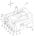
- FIG. 1 is a perspective view of the connector of Embodiment 1.
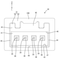
- FIG. 2 is a front view of the male housing housing the male terminal fitting.
- FIG. 3 is a perspective view of the female housing.
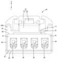
- FIG. 4 is a front view of the female housing.
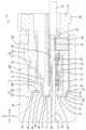
- FIG. 5 is a side sectional view of the connector.
- FIG. 6 is an explanatory diagram showing the flow of foreign matter.
- the connector of the present disclosure includes: (1) Male terminal fitting, a male side housing that accommodates the male terminal fitting; a female terminal fitting connected to the male terminal fitting; a female side housing that accommodates the female terminal fitting,
- the male housing has a cylindrical hood into which the female housing fits,
- the female housing has a facing surface that faces a rear surface of the hood portion in a fitted state in which the female housing is fitted to the hood portion,
- the opposing surface has a first opposing surface in which the insertion opening of the male terminal fitting is open, and a second opposing surface that is disposed between the first opposing surface and the female side stepped surface,
- a direction in which the female housing fits into the hood part is a fitting direction
- a direction in which the female housing separates from the hood part is a detachment direction
- a direction intersecting the fitting direction is a vertical direction.
- the second opposing surface is located above the first opposing surface and shifted from the first opposing surface in the fitting direction or the disengaging direction,
- the inner surface is arranged between a first inner surface facing the first opposing surface, a second inner surface opposing the second opposing surface, and between the first inner surface and the second inner surface. It has a male step surface facing the female step surface.
- the first opposing surface may be arranged closer to the fitting direction than the second opposing surface, and the first inner surface may be arranged closer to the fitting direction than the second inner surface. good.
- the female housing may have a discharge hole that opens in at least one of the female step surface and the second opposing surface.
- the bottom surface of the inner circumferential surface of the discharge hole may have an inclined surface inclined diagonally downward toward the detachment direction.
- the back surface has a third back surface disposed below the first back surface, and the inner circumferential surface of the hood portion has a discharge groove extending from the third back surface. You can leave it there.
- the third inner surface may be disposed on the detachment direction side with respect to the first inner surface with a second male step surface interposed between the third inner surface and the first inner surface.
- the second male step surface may have a slope portion that slopes diagonally downward toward the detachment direction.
- the male housing may have a convex portion protruding from the first inner surface.
- the convex portion may be placed in the insertion hole in the fitted state.
- the male terminal fitting may protrude from the tip of the protrusion.
- the part of the male terminal metal fitting that is disposed on the outside (on the mating direction side) of the insertion hole is covered by the convex part, so that foreign objects can be transferred along the outer periphery of the male terminal metal fitting. This makes it difficult for foreign objects to reach the male terminal fittings.
- FIG. 1 shows a connector 10 according to a first embodiment.
- the connector 10 includes a male terminal fitting 20, a male housing 30, a female terminal fitting 50, a female housing 60, and a retainer 90.
- the male housing 30 and the female housing 60 fit into each other.
- the direction in which the female housing 60 fits into the male housing 30 is referred to as the front
- the direction in which the female housing 60 separates from the male housing 30 is referred to as the rear.
- the up-down direction shown in FIGS. 2, 4, 5, and 6 is taken as the up-down direction.
- the left-right direction shown in FIGS. 2 and 4 is defined as the width direction.
- the front is written as "F”, the rear as "R”, the upper part as "U”, and the lower part as "L".
- the male terminal fitting 20 has electrical conductivity.
- the male terminal fitting 20 is made of metal, for example.
- the male terminal fitting 20 has a base 21 and a tab 22, as shown in FIG.
- the tab 22 is arranged on the rear side of the base 21 and protrudes rearward. That is, the base 21 and the tab 22 extend in the front-rear direction.
- a plurality of male terminal fittings 20 are provided at intervals in the width direction.
- the male housing 30 accommodates a plurality of male terminal fittings 20.
- the male housing 30 has insulation properties.
- the male housing 30 is made of synthetic resin, for example.
- the male housing 30 has a hood portion 31, as shown in FIGS. 2 and 5.
- the hood portion 31 has a cylindrical shape that is open to the rear, more specifically a rectangular cylindrical shape.
- the hood portion 31 includes a wall portion 32 and a cylindrical portion 33 that protrudes rearward from the outer periphery of the wall portion 32 in a cylindrical shape (more specifically, a rectangular cylindrical shape).
- the wall portion 32 has a thickness in the front-back direction.
- the thickness of the wall portion 32 is set arbitrarily.
- the wall portion 32 has a through hole 34 that accommodates the base portion 21 of the male terminal fitting 20.
- the through hole 34 penetrates the wall portion 32 in the front-back direction.
- the male terminal fitting 20 may be held within the through hole 34 by insert molding, for example.
- the tab 22 of the male terminal fitting 20 protrudes rearward from the rear surface of the wall portion 32 and is disposed in a protruding form into the hood portion 31.
- a plurality of (four in this embodiment) through holes 34 are provided at intervals in the width direction. The male terminal fittings 20 are inserted into the plurality of through holes 34, respectively.
- a rear surface 40 of the hood portion 31 is formed on the rear surface of the wall portion 32. As shown in FIG. 2, the back surface 40 extends in the vertical direction and the width direction, and faces rearward.
- the back surface 40 has a first back surface 41 , a second back surface 42 , a third back surface 43 , a fourth back surface 44 , and a fifth back surface 45 .
- the first back surface 41, the second back surface 42, the third back surface 43, the fourth back surface 44, and the fifth back surface 45 are flat surfaces facing rearward.
- the second back surface 42, the third back surface 43, the fourth back surface 44, and the fifth back surface 45 are continuous surfaces without any level difference.
- the second inner surface 42 is arranged above the first inner surface 41 with the male side step surface 46 interposed therebetween.
- the second back surface 42 is arranged on the rear side of the first back surface 41.
- the lower end of the second inner surface 42 is continuous with the rear end of the male step surface 46, and the upper end of the first inner surface 41 is continuous with the front end of the male step surface 46.
- the male step surface 46 extends in the front-rear direction and width direction, and faces downward.
- the third inner surface 43 is arranged below the first inner surface 41 with the second male step surface 47 interposed therebetween.
- the third back surface 43 is arranged on the rear side of the first back surface 41.
- the upper end of the third inner surface 43 is continuous with the rear end of the second male step surface 47
- the lower end of the first inner surface 41 is continuous with the front end of the second male step surface 47 .
- the second male step surface 47 extends in the front-rear direction and the width direction, and faces upward.
- the second male step surface 47 has a slope portion 47A that slopes diagonally downward toward the rear (see FIG. 5).
- the fourth inner surface 44 is arranged on one side in the width direction than the first inner surface 41, and the fifth inner surface 45 is arranged on the other side in the width direction than the first inner surface 41.
- the fourth inner surface 44 is flush with the second inner surface 42 and is also flush with the third inner surface 43.
- the fifth inner surface 45 is flush with the second inner surface 42 and is also flush with the third inner surface 43.
- the wall portion 32 has a convex portion 48 that protrudes rearward from the first inner surface 41.
- the convex portions 48 are provided corresponding to each through hole 34, and a plurality of convex portions (four in this embodiment) are provided at intervals in the width direction.
- the through hole 34 penetrates the wall portion 32 in the front-rear direction so as to pass through the convex portion 48 .
- the tab 22 of the male terminal fitting 20 projects rearward from an opening formed at the tip of the convex portion 48 .
- the convex portion 48 enters into the insertion opening 68 of the female housing 60 in the fitted state in which the female housing 60 is fitted to the hood portion 31 of the male housing 30.
- the cylindrical portion 33 has a cylindrical shape as described above.
- a bottom surface of the inner circumferential surface of the cylindrical portion 33 (that is, the inner circumferential surface of the hood portion 31) has a discharge groove 49.
- the discharge groove 49 extends rearward from the third inner surface 43.
- the discharge groove 49 extends to the rear end of the hood portion 31.
- the cylindrical portion 33 has a locking hole 33A that locks the female housing 60, as shown in FIG.
- the locking hole 33A passes through the top wall 33B of the cylindrical portion 33 in the vertical direction.
- the female terminal fitting 50 has electrical conductivity.
- the female terminal fitting 50 is made of metal, for example.
- the female terminal fitting 50 is formed, for example, by bending a metal plate.
- the female terminal fitting 50 has a main body portion 51 and a wire connection portion 52, as shown in FIG.
- the main body portion 51 has a cylindrical shape, and the tab 22 is inserted inside. Thereby, the female terminal fitting 50 is electrically connected to the male terminal fitting 20.
- a conductor 92 of an electric wire 91 is electrically connected to the electric wire connecting portion 52 by crimping or the like.
- a plurality of female terminal fittings 50 (four in this embodiment) are provided at intervals in the width direction.
- the female housing 60 accommodates a plurality of female terminal fittings 50.
- the female housing 60 has insulation properties.
- the female housing 60 is made of synthetic resin, for example.
- the female housing 60 has a facing surface 60A that faces the inner surface 40 of the hood portion 31 in the fitted state in which the female housing 60 is fitted to the hood portion 31 of the male housing 30. are doing.
- the opposing surface 60A is formed on the front surface of the female housing 60.
- the opposing surface 60A includes a first opposing surface 61, a second opposing surface 62, a third opposing surface 63, a fourth opposing surface 64, and a fifth opposing surface 65. ing.
- the first opposing surface 61, the second opposing surface 62, the third opposing surface 63, the fourth opposing surface 64, and the fifth opposing surface 65 are flat surfaces facing forward.
- the second opposing surface 62, the third opposing surface 63, the fourth opposing surface 64, and the fifth opposing surface 65 are continuous surfaces without steps.
- the first opposing surface 61 faces the first inner surface 41.
- the second opposing surface 62 faces the second inner surface 42 .
- the third opposing surface 63 faces the third inner surface 43.
- the fourth opposing surface 64 faces the fourth inner surface 44 .
- the fifth opposing surface 65 faces the fifth inner surface 45.
- the second opposing surface 62 is disposed above the first opposing surface 61 with a female step surface 66 in between.
- the second opposing surface 62 is arranged on the rear side of the first opposing surface 61.
- the lower end of the second opposing surface 62 is connected to the rear end of the female step surface 66
- the upper end of the first opposing surface 61 is connected to the front end of the female step surface 66 .
- the female side stepped surface 66 extends in the front-rear direction and the width direction, and faces upward.
- the female step surface 66 faces the male step surface 46 in the fitted state.
- the third opposing surface 63 is arranged below the first opposing surface 61 via the second female step surface 67.
- the third opposing surface 63 is arranged on the rear side of the first opposing surface 61.
- the upper end of the third opposing surface 63 is connected to the rear end of the second female step surface 67
- the lower end of the first opposing surface 61 is connected to the front end of the second female step surface 67 .
- the second female side step surface 67 is inclined downward toward the rear and faces downward.
- the second female step surface 67 faces the second male step surface 47 in the fitted state.
- the fourth opposing surface 64 is arranged on one side in the width direction than the first opposing surface 61, and the fifth opposing surface 65 is arranged on the other side in the width direction than the first opposing surface 61. placed on the side.
- the fourth opposing surface 64 is flush with the second opposing surface 62 and is also flush with the third opposing surface 63.
- the fifth opposing surface 65 is flush with the second opposing surface 62 and is also flush with the third opposing surface 63.
- the female housing 60 has an insertion port 68 that opens to the first opposing surface 61, a cavity 69 that communicates with the insertion port 68, and a lance 70.
- the male terminal fitting 20 is inserted into the insertion hole 68 .
- a plurality of insertion holes 68 (four in this embodiment) are provided at intervals in the width direction (see FIGS. 3 and 4).
- the front end of the cavity 69 communicates with the insertion port 68.
- a cavity 69 is provided corresponding to each insertion port 68.
- a female terminal fitting 50 is arranged within the cavity 69.
- the lance 70 projects into the cavity 69 from below the cavity 69.
- the lance 70 locks the female terminal fitting 50 disposed within the cavity 69 from behind.
- the female housing 60 has a discharge hole 71, as shown in FIGS. 3 to 5.
- the discharge hole 71 is formed in the second opposing surface 62.
- the discharge hole 71 can also be considered to be formed between the second opposing surface 62 and the female step surface 66.
- the discharge hole 71 has a long shape in the width direction.
- the discharge hole 71 is arranged across the plurality of insertion holes 68 in the width direction.
- the bottom surface of the inner peripheral surface of the discharge hole 71 has a flat horizontal surface 72 and an inclined surface 73 that slopes downward toward the rear.
- the front end of the horizontal surface 72 is continuous with the rear end of the female step surface 66 and is flush with the female step surface 66 .
- the front end of the inclined surface 73 is connected to the rear end of the horizontal surface 72.
- the female housing 60 includes a housing body 74, a construction portion 75, and a lock arm 76.
- the housing body 74 has the cavity 69 described above.
- the construction portion 75 has a shape in which it rises from both sides in the width direction of the upper surface of the housing body 74 on the front end side of the housing body 74 and has upper end portions connected to each other.
- a region surrounded by the housing body 74 and the construction portion 75 is the discharge hole 71 .
- the lock arm 76 includes an arm portion 77 extending rearward from the top surface of the construction portion 75 in a cantilevered manner, and a locking portion 78 formed on the top surface of the arm portion 77 .
- the lock arm 76 is pressed by the open end of the hood part 31 and bends downward as it enters the hood part 31. By entering into the locking hole 33A, it is locked to the hood portion 31. This maintains the fitted state.
- the retainer 90 is locked to the female housing 60 and prevents the female terminal fitting 50 disposed in the cavity 69 from coming off backward.
- the second opposing surface 62 is arranged above the first opposing surface 61 where the insertion port 68 opens, with the female side step surface 66 interposed therebetween.
- the second opposing surface 62 is arranged on the rear side of the first opposing surface 61.
- the female side stepped surface 66 faces upward. Therefore, even if the foreign matter moves forward on the upper surface of the lock arm 76 and reaches the second opposing surface 62, it tends to stay on the female side stepped surface 66 and becomes difficult to reach the first opposing surface 61. As a result, foreign objects are less likely to come into contact with the male terminal fitting 20.
- a discharge hole 71 is opened in the second opposing surface 62. Therefore, foreign matter that has reached the second opposing surface 62 is easily discharged into the discharge hole 71. Therefore, according to this configuration, it becomes even more difficult for the foreign matter to reach the first facing surface 61, and contact between the foreign matter and the male terminal fitting 20 can be more reliably prevented.
- the bottom surface of the inner peripheral surface of the discharge hole 71 has an inclined surface 73 that is inclined diagonally downward toward the rear. Therefore, according to this configuration, foreign matter in the discharge hole 71 can be guided rearward by the inclined surface 73.
- a third back surface 43 is arranged below the first back surface 41.
- the bottom surface of the inner peripheral surface of the hood portion 31 has a discharge groove 49 extending rearward from the third inner surface 43. According to this configuration, it is easy to discharge to the discharge groove 49 arranged below the first inner surface 41. Therefore, it is possible to prevent foreign matter from getting stuck between the first opposing surface 61 and the first rear surface 41 and continuing to contact the male terminal fitting 20.
- the third inner surface 43 is arranged on the rear side of the first inner surface 41 with a second male step surface 47 interposed between the third inner surface 43 and the first inner surface 41 .
- the second male step surface 47 has a slope portion 47A that slopes diagonally downward toward the rear. According to this configuration, foreign matter that has fallen through the gap formed between the first opposing surface 61 and the first inner surface 41 can be guided to the discharge groove 49 by the slope portion 47A.
- the male housing 30 has a convex portion 48 protruding from the inner surface 40.
- the convex portion 48 is disposed so as to enter into the insertion opening 68.
- the male terminal fitting 20 projects rearward from an opening formed at the tip of the convex portion 48 .
- the portion of the male terminal fitting 20 that is disposed outside (front side) of the insertion hole 68 is covered by the protrusion 48, so that foreign objects may travel along the outer periphery of the protrusion 48 to the male terminal. This makes it easier for foreign objects to fall below the metal fitting 20, making it difficult for foreign objects to reach the male terminal metal fitting 20.
- the second opposing surface may be arranged in front of the first opposing surface.
- the second back surface may be arranged in front of the first back surface.
- the female side stepped surface may face downward.
- the male step surface may face upward.
- the third back surface may be flush with the first back surface.
- the discharge hole may be configured to open on the female side stepped surface.
- the discharge hole may be configured to open in both the second opposing surface and the female step surface.
- the inner circumferential surface of the discharge hole may have a structure without an inclined surface.
- the inner circumferential surface of the hood portion may not have a discharge groove.
- the second male step surface may have a configuration without a slope portion.
- the male housing may be configured without a convex portion.
Landscapes
- Connector Housings Or Holding Contact Members (AREA)
Abstract
Description
雄端子金具と、
前記雄端子金具を収容する雄側ハウジングと、
前記雄端子金具に接続される雌端子金具と、
前記雌端子金具を収容する雌側ハウジングと、を備え、
前記雄側ハウジングは、前記雌側ハウジングが嵌合する筒状のフード部を有し、
前記雌側ハウジングは、前記雌側ハウジングが前記フード部に嵌合した嵌合状態において前記フード部の奥面と対向する対向面を有し、
前記対向面は、前記雄端子金具の挿通口が開口する第1対向面と、前記第1対向面との間に雌側段差面を介して配置される第2対向面と、を有し、
前記雌側ハウジングが前記フード部に対して嵌合する方向を嵌合方向とし、前記雌側ハウジングが前記フード部から離脱する方向を離脱方向とし、前記嵌合方向と交差する方向を上下方向とした場合に、前記第2対向面は、前記第1対向面よりも上側で且つ前記第1対向面とは前記嵌合方向又は前記離脱方向に位置をずらして配置され、
前記奥面は、前記第1対向面と対向する第1奥面と、前記第2対向面と対向する第2奥面と、前記第1奥面と前記第2奥面との間に配置され前記雌側段差面と対向する雄側段差面と、を有する。
最初に本開示の実施態様を列記して説明する。
本開示のコネクタは、
(1)雄端子金具と、
前記雄端子金具を収容する雄側ハウジングと、
前記雄端子金具に接続される雌端子金具と、
前記雌端子金具を収容する雌側ハウジングと、を備え、
前記雄側ハウジングは、前記雌側ハウジングが嵌合する筒状のフード部を有し、
前記雌側ハウジングは、前記雌側ハウジングが前記フード部に嵌合した嵌合状態において前記フード部の奥面と対向する対向面を有し、
前記対向面は、前記雄端子金具の挿通口が開口する第1対向面と、前記第1対向面との間に雌側段差面を介して配置される第2対向面と、を有し、
前記雌側ハウジングが前記フード部に対して嵌合する方向を嵌合方向とし、前記雌側ハウジングが前記フード部から離脱する方向を離脱方向とし、前記嵌合方向と交差する方向を上下方向とした場合に、前記第2対向面は、前記第1対向面よりも上側で且つ前記第1対向面とは前記嵌合方向又は前記離脱方向に位置をずらして配置され、
前記奥面は、前記第1対向面と対向する第1奥面と、前記第2対向面と対向する第2奥面と、前記第1奥面と前記第2奥面との間に配置され前記雌側段差面と対向する雄側段差面と、を有する。
本開示の具体例を、以下に図面を参照しつつ説明する。なお、本発明はこれらの例示に限定されるものではなく、請求の範囲によって示され、請求の範囲と均等の意味および範囲内でのすべての変更が含まれることが意図される。
図1には、実施形態1のコネクタ10が開示されている。コネクタ10は、図5に示すように、雄端子金具20と、雄側ハウジング30と、雌端子金具50と、雌側ハウジング60と、リテーナ90と、を備えている。
雄端子金具20は、導電性を有している。雄端子金具20は、例えば金属製である。雄端子金具20は、図5に示すように、基部21と、タブ22と、を有している。タブ22は、基部21よりも後側に配置され、後方に向けて突出している。つまり、基部21及びタブ22は、前後方向に延びている。雄端子金具20は、幅方向に間隔をあけて複数(本実施形態では4本)設けられている。
雄側ハウジング30は、複数の雄端子金具20を収容する。雄側ハウジング30は、絶縁性を有している。雄側ハウジング30は、例えば合成樹脂製である。雄側ハウジング30は、図2及び図5に示すように、フード部31を有している。フード部31は、後方に開放された筒状、より具体的には角筒状をなしている。フード部31は、壁部32と、壁部32の外周から後方に向けて筒状(より具体的には角筒状)に突出した筒部33と、を有している。
雌端子金具50は、導電性を有している。雌端子金具50は、例えば金属製である。雌端子金具50は、例えば金属板を曲げ加工して形成される。雌端子金具50は、図5に示すように、本体部51と、電線接続部52と、を有している。本体部51は、筒状をなしており、内部にタブ22が挿入される。これにより、雌端子金具50が雄端子金具20と電気的に接続される。電線接続部52には、圧着などによって電線91の導体92が電気的に接続される。雌端子金具50は、幅方向に間隔をあけて複数(本実施形態では4本)設けられている。
雌側ハウジング60は、複数の雌端子金具50を収容する。雌側ハウジング60は、絶縁性を有している。雌側ハウジング60は、例えば合成樹脂製である。雌側ハウジング60は、図5に示すように、雌側ハウジング60が雄側ハウジング30のフード部31に嵌合した嵌合状態において、フード部31の奥面40と対向する対向面60Aを有している。対向面60Aは、雌側ハウジング60の前面に形成されている。対向面60Aは、図4に示すように、第1対向面61と、第2対向面62と、第3対向面63と、第4対向面64と、第5対向面65と、を有している。第1対向面61、第2対向面62、第3対向面63、第4対向面64、及び第5対向面65は、平坦な面であり、前方を向いている。第2対向面62、第3対向面63、第4対向面64、及び第5対向面65は、段差なく連続した面である。
リテーナ90は、雌側ハウジング60に係止され、キャビティ69内に配置された雌端子金具50の後方への抜けを防止する。
コネクタ10は、嵌合状態において、雄側ハウジング30と雌側ハウジング60との間の隙間に異物が侵入するおそれがある。例えば、コネクタ10が油中環境下に置かれる場合、ロックアーム76の上面にモータの金属屑などの異物とともに油が飛散する。異物は、図6に示す矢印のように、油に流されてロックアーム76の上面を移動し、雄側ハウジング30と雌側ハウジング60との間の隙間に侵入するおそれがある。そして、異物が侵入すると、雄端子金具20が、幅方向に間隔をあけて配置される別の雄端子金具20などに対し、異物を介して短絡するおそれがある。そこで、異物が雄端子金具20に接触しにくくなるようにすることが求められる。
今回開示された実施の形態はすべての点で例示であって制限的なものではないと考えるべきである。
(1)第2対向面は、第1対向面よりも前側に配置される構成であってもよい。第2奥面は、第1奥面よりも前側に配置される構成であってもよい。雌側段差面は、下方を向いていてもよい。雄側段差面は、上方を向いていてもよい。
(2)第3奥面は、第1奥面と面一であってもよい。
(3)排出孔は、雌側段差面に開口する構成であってもよい。排出孔は、第2対向面と雌側段差面の両方に開口する構成であってもよい。
(4)排出孔の内周面は、傾斜面を有しない構成であってもよい。
(5)フード部の内周面は、排出溝を有しない構成であってもよい。
(6)第2雄側段差面は、スロープ部を有しない構成であってもよい。
(7)雄側ハウジングは、凸部を有しない構成であってもよい。
20 :雄端子金具
21 :基部
22 :タブ
30 :雄側ハウジング
31 :フード部
32 :壁部
33 :筒部
33A :係止孔
33B :天壁
34 :貫通孔
40 :奥面
41 :第1奥面
42 :第2奥面
43 :第3奥面
44 :第4奥面
45 :第5奥面
46 :雄側段差面
47 :第2雄側段差面
47A :スロープ部
48 :凸部
49 :排出溝
50 :雌端子金具
51 :本体部
52 :電線接続部
60 :雌側ハウジング
60A :対向面
61 :第1対向面
62 :第2対向面
63 :第3対向面
64 :第4対向面
65 :第5対向面
66 :雌側段差面
67 :第2雌側段差面
68 :挿通口
69 :キャビティ
70 :ランス
71 :排出孔
72 :水平面
73 :傾斜面
74 :ハウジング本体
75 :架設部
76 :ロックアーム
77 :アーム部
78 :係止部
90 :リテーナ
91 :電線
92 :導体
Claims (8)
- 雄端子金具と、
前記雄端子金具を収容する雄側ハウジングと、
前記雄端子金具に接続される雌端子金具と、
前記雌端子金具を収容する雌側ハウジングと、を備え、
前記雄側ハウジングは、前記雌側ハウジングが嵌合する筒状のフード部を有し、
前記雌側ハウジングは、前記雌側ハウジングが前記フード部に嵌合した嵌合状態において前記フード部の奥面と対向する対向面を有し、
前記対向面は、前記雄端子金具の挿通口が開口する第1対向面と、前記第1対向面との間に雌側段差面を介して配置される第2対向面と、を有し、
前記雌側ハウジングが前記フード部に対して嵌合する方向を嵌合方向とし、前記雌側ハウジングが前記フード部から離脱する方向を離脱方向とし、前記嵌合方向と交差する方向を上下方向とした場合に、前記第2対向面は、前記第1対向面よりも上側で且つ前記第1対向面とは前記嵌合方向又は前記離脱方向に位置をずらして配置され、
前記奥面は、前記第1対向面と対向する第1奥面と、前記第2対向面と対向する第2奥面と、前記第1奥面と前記第2奥面との間に配置され前記雌側段差面と対向する雄側段差面と、を有するコネクタ。 - 前記第1対向面は、前記第2対向面よりも前記嵌合方向側に配置され、前記第1奥面は、前記第2奥面よりも前記嵌合方向側に配置される請求項1に記載のコネクタ。
- 前記雌側ハウジングは、前記雌側段差面及び前記第2対向面の少なくともいずれか一方に開口する排出孔を有する請求項2に記載のコネクタ。
- 前記排出孔の内周面の底面は、前記離脱方向側に向けて斜め下方に傾斜した傾斜面を有する請求項3に記載のコネクタ。
- 前記奥面は、前記第1奥面よりも下側に配置される第3奥面を有し、
前記フード部の内周面は、前記第3奥面から延びる排出溝を有する請求項1から請求項4のいずれか一項に記載のコネクタ。 - 前記第3奥面は、前記第1奥面との間に第2雄側段差面を介して、前記第1奥面に対し前記離脱方向側に配置され、
前記第2雄側段差面は、前記離脱方向側に向けて斜め下方に傾斜したスロープ部を有する請求項5に記載のコネクタ。 - 前記雄側ハウジングは、前記第1奥面から突出した凸部を有し、
前記凸部は、前記嵌合状態において前記挿通口内に入り込んだ状態で配置され、
前記雄端子金具は、前記凸部の先端部から突出している請求項6に記載のコネクタ。 - 前記雄側ハウジングは、前記第1奥面から突出した凸部を有し、
前記凸部は、前記嵌合状態において前記挿通口内に入り込んだ状態で配置され、
前記雄端子金具は、前記凸部の先端部から突出している請求項1又は請求項2に記載のコネクタ。
Priority Applications (1)
| Application Number | Priority Date | Filing Date | Title |
|---|---|---|---|
| CN202380030065.8A CN118923007A (zh) | 2022-04-13 | 2023-04-10 | 连接器 |
Applications Claiming Priority (2)
| Application Number | Priority Date | Filing Date | Title |
|---|---|---|---|
| JP2022066076A JP7769872B2 (ja) | 2022-04-13 | 2022-04-13 | コネクタ |
| JP2022-066076 | 2022-04-13 |
Publications (1)
| Publication Number | Publication Date |
|---|---|
| WO2023199891A1 true WO2023199891A1 (ja) | 2023-10-19 |
Family
ID=88329728
Family Applications (1)
| Application Number | Title | Priority Date | Filing Date |
|---|---|---|---|
| PCT/JP2023/014563 Ceased WO2023199891A1 (ja) | 2022-04-13 | 2023-04-10 | コネクタ |
Country Status (3)
| Country | Link |
|---|---|
| JP (1) | JP7769872B2 (ja) |
| CN (1) | CN118923007A (ja) |
| WO (1) | WO2023199891A1 (ja) |
Citations (5)
| Publication number | Priority date | Publication date | Assignee | Title |
|---|---|---|---|---|
| US4886471A (en) * | 1987-01-30 | 1989-12-12 | Amp Incorporated | Vacuum seal for electrical connector |
| JP2007258041A (ja) * | 2006-03-24 | 2007-10-04 | Tyco Electronics Amp Kk | 防水型電気コネクタ |
| WO2012165635A1 (ja) * | 2011-06-03 | 2012-12-06 | 矢崎総業株式会社 | コネクタユニット |
| JP2013239368A (ja) * | 2012-05-16 | 2013-11-28 | Auto Network Gijutsu Kenkyusho:Kk | 防水コネクタ |
| JP2016157673A (ja) * | 2015-02-25 | 2016-09-01 | 矢崎総業株式会社 | コネクタの防水構造 |
-
2022
- 2022-04-13 JP JP2022066076A patent/JP7769872B2/ja active Active
-
2023
- 2023-04-10 WO PCT/JP2023/014563 patent/WO2023199891A1/ja not_active Ceased
- 2023-04-10 CN CN202380030065.8A patent/CN118923007A/zh active Pending
Patent Citations (5)
| Publication number | Priority date | Publication date | Assignee | Title |
|---|---|---|---|---|
| US4886471A (en) * | 1987-01-30 | 1989-12-12 | Amp Incorporated | Vacuum seal for electrical connector |
| JP2007258041A (ja) * | 2006-03-24 | 2007-10-04 | Tyco Electronics Amp Kk | 防水型電気コネクタ |
| WO2012165635A1 (ja) * | 2011-06-03 | 2012-12-06 | 矢崎総業株式会社 | コネクタユニット |
| JP2013239368A (ja) * | 2012-05-16 | 2013-11-28 | Auto Network Gijutsu Kenkyusho:Kk | 防水コネクタ |
| JP2016157673A (ja) * | 2015-02-25 | 2016-09-01 | 矢崎総業株式会社 | コネクタの防水構造 |
Also Published As
| Publication number | Publication date |
|---|---|
| JP7769872B2 (ja) | 2025-11-14 |
| JP2023156607A (ja) | 2023-10-25 |
| CN118923007A (zh) | 2024-11-08 |
Similar Documents
| Publication | Publication Date | Title |
|---|---|---|
| KR100937183B1 (ko) | 커넥터 및 커넥터의 예조립 방법 | |
| CN100499278C (zh) | 连接器和连接器装置 | |
| US7575464B2 (en) | Connector with channel-shaped clearance between lock arm and projection to prevent entry of wires | |
| US9246260B2 (en) | Electrical connector | |
| US6568948B2 (en) | Connector | |
| JP7454124B2 (ja) | シールドコネクタ | |
| EP1137111A2 (en) | A watertight connector and sealing member | |
| CN115882301A (zh) | 连接器 | |
| JP2023077166A (ja) | シールド端子およびコネクタ | |
| CN115882299A (zh) | 连接器 | |
| US6398599B1 (en) | Male contact having contact entangling prevention means | |
| CN110323613A (zh) | 连接器及端子零件 | |
| WO2023199891A1 (ja) | コネクタ | |
| CN114759401B (zh) | 连接器及连接器装置 | |
| CN115882298A (zh) | 连接器 | |
| US7419399B2 (en) | Panel mount connector with integrated latch and polarizing key | |
| CN100505434C (zh) | 多连接型插头连接器以及纵叠型和横置型插座连接器 | |
| JP7685147B2 (ja) | 端子及びコネクタ | |
| US6669508B2 (en) | Connector | |
| JP2013258067A (ja) | コネクタ | |
| JP2022109000A (ja) | レバー式コネクタ | |
| JP2023077159A (ja) | コネクタ | |
| CN1111835A (zh) | 双重锁定式电连接器 | |
| US12341285B2 (en) | Connector with strength reduction suppressible lance | |
| US20250239808A1 (en) | Connector |
Legal Events
| Date | Code | Title | Description |
|---|---|---|---|
| 121 | Ep: the epo has been informed by wipo that ep was designated in this application |
Ref document number: 23788309 Country of ref document: EP Kind code of ref document: A1 |
|
| WWE | Wipo information: entry into national phase |
Ref document number: 202380030065.8 Country of ref document: CN |
|
| WWE | Wipo information: entry into national phase |
Ref document number: 18854981 Country of ref document: US |
|
| NENP | Non-entry into the national phase |
Ref country code: DE |
|
| 122 | Ep: pct application non-entry in european phase |
Ref document number: 23788309 Country of ref document: EP Kind code of ref document: A1 |