WO2023199731A1 - 遠心ファン - Google Patents
遠心ファン Download PDFInfo
- Publication number
- WO2023199731A1 WO2023199731A1 PCT/JP2023/011994 JP2023011994W WO2023199731A1 WO 2023199731 A1 WO2023199731 A1 WO 2023199731A1 JP 2023011994 W JP2023011994 W JP 2023011994W WO 2023199731 A1 WO2023199731 A1 WO 2023199731A1
- Authority
- WO
- WIPO (PCT)
- Prior art keywords
- tangent
- blade
- trailing edge
- angle
- shroud
- Prior art date
- Legal status (The legal status is an assumption and is not a legal conclusion. Google has not performed a legal analysis and makes no representation as to the accuracy of the status listed.)
- Ceased
Links
Images


Classifications
-
- F—MECHANICAL ENGINEERING; LIGHTING; HEATING; WEAPONS; BLASTING
- F04—POSITIVE - DISPLACEMENT MACHINES FOR LIQUIDS; PUMPS FOR LIQUIDS OR ELASTIC FLUIDS
- F04D—NON-POSITIVE-DISPLACEMENT PUMPS
- F04D29/00—Details, component parts, or accessories
- F04D29/40—Casings; Connections of working fluid
- F04D29/42—Casings; Connections of working fluid for radial or helico-centrifugal pumps
- F04D29/4206—Casings; Connections of working fluid for radial or helico-centrifugal pumps especially adapted for elastic fluid pumps
- F04D29/4226—Fan casings
-
- F—MECHANICAL ENGINEERING; LIGHTING; HEATING; WEAPONS; BLASTING
- F04—POSITIVE - DISPLACEMENT MACHINES FOR LIQUIDS; PUMPS FOR LIQUIDS OR ELASTIC FLUIDS
- F04D—NON-POSITIVE-DISPLACEMENT PUMPS
- F04D17/00—Radial-flow pumps, e.g. centrifugal pumps; Helico-centrifugal pumps
- F04D17/08—Centrifugal pumps
-
- F—MECHANICAL ENGINEERING; LIGHTING; HEATING; WEAPONS; BLASTING
- F04—POSITIVE - DISPLACEMENT MACHINES FOR LIQUIDS; PUMPS FOR LIQUIDS OR ELASTIC FLUIDS
- F04D—NON-POSITIVE-DISPLACEMENT PUMPS
- F04D29/00—Details, component parts, or accessories
- F04D29/26—Rotors specially for elastic fluids
- F04D29/28—Rotors specially for elastic fluids for centrifugal or helico-centrifugal pumps for radial-flow or helico-centrifugal pumps
- F04D29/281—Rotors specially for elastic fluids for centrifugal or helico-centrifugal pumps for radial-flow or helico-centrifugal pumps for fans or blowers
-
- F—MECHANICAL ENGINEERING; LIGHTING; HEATING; WEAPONS; BLASTING
- F04—POSITIVE - DISPLACEMENT MACHINES FOR LIQUIDS; PUMPS FOR LIQUIDS OR ELASTIC FLUIDS
- F04D—NON-POSITIVE-DISPLACEMENT PUMPS
- F04D29/00—Details, component parts, or accessories
- F04D29/26—Rotors specially for elastic fluids
- F04D29/28—Rotors specially for elastic fluids for centrifugal or helico-centrifugal pumps for radial-flow or helico-centrifugal pumps
- F04D29/30—Vanes
Definitions
- the present disclosure relates to a centrifugal fan.
- centrifugal fans used for blowers have been known.
- the skew angle of a portion of the blade on the trailing edge side is smaller than the skew angle of the portion of the blade on the leading edge side.
- this centrifugal fan suppresses secondary flow vortices that occur in the wind flowing through the flow path formed between a plurality of blades adjacent in the rotation direction (hereinafter referred to as "inter-blade flow path"). This reduces noise and improves boost characteristics.
- the skew angle refers to the angle formed on the suction surface side of the blade between the line segment connecting the point where the blade connects to the main plate and the point where the blade connects to the shroud and the main plate.
- An object of the present disclosure is to provide a centrifugal fan that can reduce noise and increase air blowing efficiency by making the speed distribution of air blown from blade outlets more uniform.
- a centrifugal fan includes a shroud, a main plate, and a plurality of blades.
- the shroud is annularly shaped and has an air inlet in the center.
- the main plate is provided facing the shroud and rotates together with the shroud.
- the plurality of blades are arranged at predetermined intervals in the rotational direction between the shroud and the main plate, and are connected to the shroud and the main plate.
- a tangent that passes through the trailing edge of a predetermined blade is referred to as a first tangent.
- the tangent that passes through the trailing edge of a predetermined wing is referred to as a second tangent.
- the angle on the outside of the virtual circle with respect to the second tangent and on the front side of the first tangent in the rotational direction is referred to as an exit angle.
- the exit angle of the portion of the trailing edge adjacent to the main plate and the exit angle of the portion of the trailing edge adjacent to the shroud is greater than the exit angle of the portion of the trailing edge where the exit angle is maximum. small.
- the first form is a form in which both the exit angle of a portion of the trailing edge adjacent to the main plate and the exit angle of a portion of the trailing edge adjacent to the shroud are reduced.
- the second form is a form in which the exit angle of a portion of the trailing edge adjacent to the main plate is made small.
- the third form is a form in which the exit angle of a portion of the trailing edge adjacent to the shroud is made small.
- the region adjacent to the main plate is the region closer to the main plate than the inflection point closest to the main plate
- the region adjacent to the shroud is the region closer to the shroud than the inflection point closest to the shroud. This is the part of the body.
- the trailing edge is temporarily set parallel to the axis. This is effective when the wind speed in the area on the shroud side of the blade outlet and the wind speed in the area on the main plate side are both slow, and the wind speed in the central part of the blade outlet in the axial direction becomes high. Note that the wind speed in the region of the blade outlet on the main plate side may be slowed down by the influence of a boundary layer caused by friction between the main plate and the air.
- the wind speed in the region of the blade outlet on the shroud side may be slowed down by the influence of vortices and the like generated near the shroud in the inter-blade flow path.
- the wind speed in those areas can be adjusted relative to other parts. accelerate.
- the centrifugal fan can reduce noise and increase air blowing efficiency by making the speed distribution of the air blown from the blade outlet close to uniform.
- the centrifugal fan can reduce noise and increase air blowing efficiency by making the speed distribution of the air blown from the blade outlet close to uniform.
- the centrifugal fan can reduce noise and increase air blowing efficiency by making the speed distribution of the air blown from the blade outlet close to uniform.
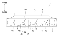
- FIG. 1 is a perspective view of a centrifugal fan according to a first embodiment.
- FIG. 2 is a cross-sectional view of the centrifugal fan according to the first embodiment taken parallel to the axis of rotation.
- FIG. 2 is a side view of the centrifugal fan according to the first embodiment.
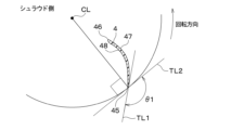
- 4 is an enlarged view of part IV in FIG. 3.
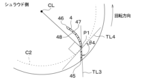
- FIG. 5 is a diagram illustrating an exit angle on the pressure side of a portion adjacent to the shroud in a cross section taken along the line VV in FIG. 4.
- FIG. FIG. 5 is a diagram illustrating an exit angle on the positive pressure surface side at the central portion in the axial direction in the cross section taken along the line VI-VI in FIG.
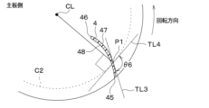
- FIG. 4; 5 is a diagram illustrating an exit angle on the pressure side of a portion adjacent to the main plate in a cross section taken along line VII-VII in FIG. 4.
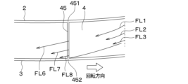
- FIG. FIG. 3 is a view of the blades of the centrifugal fan of the reference example viewed from the rotation direction, and is an explanatory diagram for explaining the wind speed in the inter-blade passage and the wind speed blown out from the blade outlet. It is a side view of the centrifugal fan of a reference example, and is an explanatory view for explaining the wind speed of the passage between blades, and the wind speed blown out from the blade outlet.
- FIG. 3 is a view of the blades of the centrifugal fan of the reference example viewed from the rotation direction, and is an explanatory diagram for explaining the wind speed in the inter-blade passage and the wind speed blown out from the blade outlet. It is a side view of the centrifugal fan of a reference example, and is an explanatory view for explaining the wind speed of the passage between
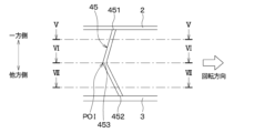
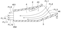
- FIG. 2 is a view of the blades of the centrifugal fan of the first embodiment viewed from the rotation direction, and is an explanatory diagram for explaining the wind speed in the inter-blade passage and the wind speed blown out from the blade outlet. It is a side view of the centrifugal fan of 1st Embodiment, and is an explanatory view for explaining the wind speed of the passage between blades, and the wind speed blown out from the blade outlet.
- FIG. 5 is a diagram illustrating the pressure side blade surface angle of a portion adjacent to the shroud in a cross section taken along the line VV in FIG. 4; FIG.
- FIG. 5 is a diagram illustrating a pressure surface side blade surface angle at the central portion in the axial direction in a cross section taken along the line VI-VI in FIG. 4;
- FIG. 5 is a diagram illustrating a pressure side blade surface angle of a portion adjacent to the main plate in a cross section taken along line VII-VII in FIG. 4;
- 5 is a diagram illustrating an outlet angle on the suction surface side of a portion adjacent to the shroud in a cross section taken along the line VV in FIG. 4.
- FIG. FIG. 5 is a diagram illustrating an outlet angle on the suction surface side at the central portion in the axial direction in the cross section taken along the line VI-VI in FIG. 4;
- FIG. 5 is a diagram illustrating an exit angle on the suction surface side of a portion adjacent to the main plate in a cross section taken along line VII-VII in FIG. 4; 5 is a diagram illustrating the suction surface side blade surface angle of a portion adjacent to the shroud in a cross section taken along the line VV in FIG. 4.
- FIG. FIG. 5 is a diagram illustrating the suction surface side blade surface angle at the central portion in the axial direction in the cross section taken along the line VI-VI in FIG. 4;
- FIG. 5 is a diagram illustrating a suction surface side blade surface angle of a portion adjacent to the main plate in a cross section taken along line VII-VII in FIG. 4;
- FIG. 5 is an enlarged side view of a portion corresponding to FIG.
- FIG. 5 is an enlarged side view of a portion corresponding to FIG. 4 in a centrifugal fan according to a second embodiment.
- FIG. 5 is an enlarged side view of a portion corresponding to FIG. 4 in a centrifugal fan according to a third embodiment.
- FIG. 5 is an enlarged side view of a portion corresponding to FIG. 4 in a centrifugal fan according to a fourth embodiment.
- FIG. 5 is an enlarged side view of a portion corresponding to FIG. 4 in a centrifugal fan according to a fifth embodiment.
- FIG. 5 is an enlarged side view of a portion corresponding to FIG. 4 in a centrifugal fan according to a sixth embodiment. It is a figure which looked at the wing
- FIG. 7 is a diagram of a blade viewed from the rotation direction in a centrifugal fan according to a tenth embodiment.
- FIG. 7 is a diagram of a blade viewed from the rotation direction in a centrifugal fan according to an eleventh embodiment.
- the centrifugal fan of the first embodiment is used in a blower included in an air conditioner, a ventilation device, or the like.
- the centrifugal fan 1 includes a shroud 2 having an air suction port, a main plate 3 provided opposite to the shroud 2, and a plurality of shrouds disposed between the shroud 2 and the main plate 3. It is equipped with 4 wings.
- the axis CL of rotation of the centrifugal fan 1 is shown by a dashed-dotted line.
- the direction in which the axis CL extends will be referred to as the axis direction.
- the radially outer side of a circle perpendicular to the axis CL and centered on the axis CL is referred to as the "radially outer side” or simply the “outer side.”
- the air suction port 21 side of the shroud 2 will be described as one side in the axial direction, and the opposite side will be described as the other side in the axial direction.
- the shroud 2 is formed into an annular shape and has an air suction port 21 in its center for sucking air.
- the shroud 2 is formed in a shape that is gradually located on the other side in the axial direction from the air suction port 21 toward the outside in the radial direction.
- the main plate 3 is formed into a disk shape, and is gradually positioned on the other side in the axial direction from the center portion toward the outside in the radial direction. In other words, the main plate 3 is formed such that the central portion thereof protrudes toward the air suction port 21 side.
- a shaft of an electric motor (not shown) is attached to the center of the main plate 3 .
- the plurality of blades 4 are arranged between the main plate 3 and the shroud 2 at predetermined intervals in the rotation direction of the centrifugal fan 1.
- a region 41 on one side in the axial direction of the plurality of blades 4 is connected to the shroud 2, and a region 42 on the other side in the axial direction is connected to the main plate 3. That is, the plurality of wings 4, shroud 2, and main plate 3 are integrally formed.
- Each of the plurality of blades 4 is provided such that the trailing edge 45 is located on the rear side in the rotational direction with respect to a virtual plane including the axis CL and the leading edge 46. Therefore, this centrifugal fan 1 is a turbo fan.
- the centrifugal fan 1 (that is, the main plate 3, the shroud 2, and the plurality of blades 4) is driven by an electric motor (not shown) to rotate in the direction of rotation shown by the arrow in FIG. 1, etc.
- an electric motor not shown
- the centrifugal fan 1 rotates, the air sucked in from the air suction port 21 flows from the leading edge 46 of the blade 4 through the inter-blade flow path 43 formed between the plurality of blades 4, and passes through the trailing edge 45 of the blade 4.
- the air is blown radially outward from the blade outlet 44 formed between the shroud 2 and the main plate 3.
- a portion 451 of the trailing edge 45 of the blade 4 that connects to the shroud 2 and a portion 452 of the trailing edge 45 of the blade 4 that connects to the main plate 3.
- the center portion 453 of the trailing edge 45 of the blade 4 in the axial direction is located on the rear side in the rotational direction.
- the leading edge 46 of the blade 4 extends from a portion 461 connected to the shroud 2 to a portion 462 connected to the main plate 3 with respect to the axis CL. They are formed substantially parallel to each other. Therefore, in this centrifugal fan 1, the central part of the blade 4 in the axial direction is connected to the leading edge 46, with respect to the part 41 of the blade 4 that connects to the shroud 2 and the part 42 of the blade 4 that connects to the main plate 3. It has a shape that is gradually located on the rear side in the rotational direction from a predetermined position in the middle of the trailing edge 45 to the trailing edge 45.
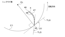
- FIG. 5 is a cross-sectional view taken along line VV in FIG. 4, that is, a cross-sectional view of a portion of the blade 4 adjacent to the shroud 2.
- FIG. 6 is a cross-sectional view taken along line VI-VI in FIG. 4, that is, a cross-sectional view of the central portion of the blade 4 in the axial direction.
- 7 is a cross-sectional view taken along line VII-VII in FIG. 4, that is, a cross-sectional view of a portion of the blade 4 adjacent to the main plate 3. As shown in FIG.
- first tangent TL1 a tangent passing through the trailing edge 45 of a predetermined blade 4 is referred to as a first tangent TL2.
- the pressure side exit angle may be simply referred to as "exit angle.”
- the exit angle of the portion of the trailing edge 45 adjacent to the shroud 2 is shown as ⁇ 1.
- the exit angle of the central portion 453 of the rear edge 45 in the axial direction is shown as ⁇ 2.
- the exit angle of a portion of the trailing edge 45 adjacent to the main plate 3 is shown as ⁇ 3.
- the exit angle ⁇ 3 of the portion of the trailing edge 45 adjacent to the main plate 3 and the exit angle ⁇ 1 of the portion of the trailing edge 45 adjacent to the shroud 2 are both , is smaller than the exit angle ⁇ 2 of the central portion 453 of the rear edge 45 in the axial direction.
- the central portion 453 of the rear edge 45 in the axial direction can be said to be a portion of the rear edge 45 where the exit angle is maximum.
- the centrifugal fan 1 of the first embodiment when looking at changes in the outlet angle at each location in the axial direction of the trailing edge 45, It is a shape in which there is one or more inflection point POI where the increase or decrease changes.
- the inflection point POI is located at the central portion 453 of the trailing edge 45 in the axial direction.
- the centrifugal fan 1 of the first embodiment has a configuration in which one or more inflection points POI exist in the trailing edge 45. Further, in this centrifugal fan 1, the exit angle ⁇ 3 of the portion of the trailing edge 45 adjacent to the main plate 3 and the exit angle ⁇ 1 of the portion of the trailing edge 45 adjacent to the shroud 2 are set in the axial direction of the trailing edge 45. This configuration is smaller than the exit angle ⁇ 2 of the central portion 453. The significance of configuring the centrifugal fan 1 of this embodiment as described above will be explained below.
- the blade 4 of the centrifugal fan of the reference example has a trailing edge 45 extending from a portion 451 connecting to the shroud 2 to a portion 452 connecting to the main plate 3, and is formed parallel to the axis CL. has been done. Therefore, the exit angle of the trailing edge 45 of the blade 4 is the same from the shroud 2 side to the main plate 3 side.
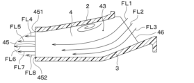
- FIGS. 8 and 9 the speed of the wind flowing through the inter-blade flow path 43 and the speed of the wind blown out from the blade outlet 44 are shown by the lengths of the arrows, respectively.
- the air sucked in in the axial direction from the air suction port 21 of the shroud 2 is directed along the main plate 3.
- the air flows through the inter-blade flow path 43 from the leading edge 46 side of the blade 4.
- the wind flow separates in the region on the shroud 2 side, and the main flow is biased toward the main plate 3 side. Due to these factors, in the interblade flow path 43, the wind speed in the axial center region and the region closer to the main plate 3 than the axial center is faster than the wind speed in the region near the shroud 2.
- arrow FL3 in the area near the main plate 3, the wind speed is reduced due to the influence of a boundary layer generated by friction between the air and the main plate 3.
- FIGS. 10 and 11 show the centrifugal fan 1 of the first embodiment. Note that in FIGS. 10 and 11 as well, the speed of the wind flowing through the inter-blade flow path 43 and the speed of the wind blown out from the blade outlet 44 are shown by the lengths of the arrows, respectively.
- the blades 4 included in the centrifugal fan 1 of the first embodiment have the configuration described above. That is, the configuration is such that there is one or more inflection points POI in the trailing edge 45, and the exit angle ⁇ 3 of the portion of the trailing edge 45 adjacent to the main plate 3 and the exit angle ⁇ 3 of the portion of the trailing edge 45 adjacent to the shroud 2.
- the exit angle ⁇ 1 of the portion is smaller than the exit angle ⁇ 2 of the central portion 453 of the rear edge 45 in the axial direction.
- the exit angle ⁇ 2 of the central portion 453 in the axial direction of the trailing edge 45 is the exit angle ⁇ 3 of the portion of the trailing edge 45 adjacent to the main plate 3, and the exit angle ⁇ 3 of the portion of the trailing edge 45 adjacent to the shroud 2. is larger than the exit angle ⁇ 1.
- the centrifugal fan 1 of the first embodiment can equalize the speed distribution of the wind blown out from the blade outlet 44.
- the outlet angle ⁇ 3 of the portion of the trailing edge 45 adjacent to the main plate 3 is made small. This makes it easier to apply force to the air flowing from the blade 4 through the inter-blade flow path 43, increasing the amount of work applied to the air flowing from the blade 4 through the inter-blade flow path 43, making it relatively It is possible to increase the wind speed. Therefore, as shown by arrow FL12, in the first embodiment, by reducing the exit angle ⁇ 3 of the portion of the trailing edge 45 adjacent to the main plate 3, Slow wind speed can be relatively accelerated compared to other parts. Therefore, the centrifugal fan 1 of the first embodiment can make the speed distribution of the wind blown from the blade outlet 44 more uniform.
- FIG. 12 shows a cross section of the same portion as FIG. 5 (that is, a portion of the blade 4 adjacent to the shroud 2).
- FIG. 13 shows a cross section of the same portion as FIG. 6 (that is, the central portion of the blade 4 in the axial direction).
- FIG. 14 shows a cross section of the same portion as FIG. 7 (that is, a portion of the wing 4 adjacent to the main plate 3).
- a predetermined position P1 (hereinafter, “ 1) is called a third tangent TL3. Also, among the tangents of a virtual circle centered on the axis CL and passing through the first predetermined position P1 (hereinafter referred to as "second virtual circle C2"), the tangent passing through the first predetermined position P1 is a fourth tangent TL4. That's what it means.
- the angle on the outside of the second virtual circle C2 with respect to the fourth tangent TL4 and on the front side in the rotational direction of the third tangent TL3 is referred to as a pressure side wing surface angle.
- the pressure side blade surface angle of the portion adjacent to the shroud 2 at the first predetermined position P1 of the blade 4 is shown as ⁇ 4.
- the pressure side blade surface angle at the center in the axial direction is shown as ⁇ 5.
- the pressure side blade surface angle of the portion adjacent to the main plate 3 at the first predetermined position P1 of the blade 4 is shown as ⁇ 6.
- the pressure surface side blade surface angle ⁇ 6 of the portion adjacent to the main plate 3 at the first predetermined position P1 of the blade 4 is set in the axial direction at the first predetermined position P1 of the blade 4.
- the pressure side blade surface angle ⁇ 4 of the portion adjacent to the shroud 2 at the first predetermined position P1 of the blade 4 is also the pressure side blade surface angle ⁇ 4 of the portion adjacent to the shroud 2 at the first predetermined position P1 of the blade 4. smaller than the angle ⁇ 5.
- the central portion of the blade 4 in the axial direction at the first predetermined position P1 can be said to be a portion where the pressure side blade surface angle is maximum at the first predetermined position P1 of the blade 4.
- FIG. 15 shows a cross section of the same portion as FIG. 5 (that is, the portion of the blade 4 adjacent to the shroud 2).
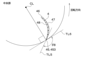
- FIG. 16 shows a cross section of the same portion as FIG. 6 (that is, the central portion of the blade 4 in the axial direction).
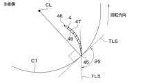
- FIG. 17 shows a cross section of the same portion as FIG. 7 (that is, the portion of the wing 4 adjacent to the main plate 3).
- the tangent that passes through the trailing edge 45 of a predetermined blade 4 is referred to as a fifth tangent TL5.
- a tangent passing through the trailing edge 45 of the predetermined blade 4 is referred to as a sixth tangent TL6.
- the suction side exit angle is referred to as the suction side exit angle.
- the suction surface exit angle of the portion of the trailing edge 45 adjacent to the shroud 2 is shown as ⁇ 7.
- the suction surface exit angle of the central portion 453 in the axial direction of the trailing edge 45 is shown as ⁇ 8.
- the suction surface exit angle of the portion of the trailing edge 45 adjacent to the main plate 3 is shown as ⁇ 9.
- the suction surface exit angle ⁇ 9 of the portion of the trailing edge 45 adjacent to the main plate 3 is smaller than the suction surface exit angle ⁇ 8 of the center portion 453 in the axial direction of the trailing edge 45.
- suction side exit angle ⁇ 7 of the portion of the trailing edge 45 adjacent to the shroud 2 is also smaller than the suction side exit angle ⁇ 8 of the central portion 453 in the axial direction of the trailing edge 45.
- the central portion 453 of the trailing edge 45 in the axial direction can be said to be a portion of the trailing edge 45 where the exit angle on the negative pressure surface side is maximum.
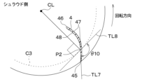
- FIG. 18 shows a cross section of the same portion as FIG. 5 (that is, a portion of the blade 4 adjacent to the shroud 2).
- FIG. 19 shows a cross section of the same portion as FIG. 6 (that is, the central portion of the blade 4 in the axial direction).
- FIG. 20 shows a cross section of the same portion as FIG. 7 (that is, the portion of the wing 4 adjacent to the main plate 3).
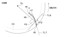
- a predetermined position P2 (hereinafter, " The tangent that passes through the predetermined position P2 of 2 is called the seventh tangent TL7. Also, among the tangents of a virtual circle centered on the axis CL and passing through the second predetermined position P2 (hereinafter referred to as "third virtual circle C3"), the tangent passing through the second predetermined position P2 is an eighth tangent TL8. That's what it means.
- the angle on the outside of the third imaginary circle C3 with respect to the eighth tangent TL8 and on the front side in the rotational direction of the seventh tangent TL7 is referred to as a suction side blade surface angle.
- the suction side blade surface angle of the portion adjacent to the shroud 2 at the second predetermined position P2 of the blade 4 is shown as ⁇ 10.
- the suction side blade surface angle at the center in the axial direction at the second predetermined position P2 of the blade 4 is shown as ⁇ 11.
- the suction surface side blade surface angle of the portion adjacent to the main plate 3 at the second predetermined position P2 of the blade 4 is shown as ⁇ 12.
- the suction surface side blade surface angle ⁇ 12 of the portion adjacent to the main plate 3 at the second predetermined position P2 of the blade 4 is set in the axial direction at the second predetermined position P2 of the blade 4.
- the suction side blade angle ⁇ 10 of the portion adjacent to the shroud 2 at the second predetermined position P2 of the blade 4 is also the same as the suction side blade surface angle ⁇ 10 of the portion adjacent to the shroud 2 at the second predetermined position P2 of the blade 4. It is smaller than the angle ⁇ 11.
- the central portion of the blade 4 in the axial direction at the second predetermined position P2 can be said to be a portion where the suction side blade surface angle is maximum at the second predetermined position P2 of the blade 4.
- the plurality of blades 4 included in the centrifugal fan 1 of this embodiment have different shapes in which the suction side exit angle and the pressure side exit angle are different, and the suction side blade angle and the pressure side blade angle are different. There is. According to this, it is possible to suppress separation of wind on the negative pressure surface 48, and furthermore, it is possible to adjust the amount of work from the blades 4 to the air on the positive pressure surface 47, so that the inter-blade flow path 43 can be adjusted. It is possible to make the wind velocity distribution of the air flowing through the air almost uniform.
- the centrifugal fan 1 of the first embodiment described above has the following effects. (1) In the centrifugal fan 1 of the first embodiment, there is one or more inflection points POI in the trailing edge 45 of the blade 4 where the exit angle changes. Furthermore, the exit angle ⁇ 3 of the portion of the trailing edge 45 adjacent to the main plate 3 and the exit angle ⁇ 1 of the portion of the trailing edge 45 adjacent to the shroud 2 are both the maximum exit angle of the trailing edge 45. It is smaller than the exit angle ⁇ 2 of the part.
- the centrifugal fan 1 if the trailing edge 45 is provided parallel to the axis CL, the wind speed in the area on the shroud 2 side of the blade outlet 44 and the wind speed in the area on the main plate 3 side are different. This is effective when the wind speed at the center of the blade outlet 44 in the axial direction becomes faster.
- the centrifugal fan 1 of the first embodiment reduces both the exit angle ⁇ 1 of the portion of the trailing edge 45 on the shroud 2 side and the exit angle ⁇ 3 of the portion of the trailing edge 45 on the main plate 3 side. The wind speed in those areas is relatively accelerated compared to other parts.
- the centrifugal fan 1 of the first embodiment can reduce noise and increase air blowing efficiency by making the speed distribution of the air blown from the blade outlet 44 close to uniform.
- the plurality of blades 4 included in the centrifugal fan 1 of the first embodiment have different exit angles on the suction side and pressure side, and different blade angles on the suction side and pressure side. It has a shape. According to this, separation of wind on the negative pressure surface 48 can be suppressed, and furthermore, the amount of work applied to the air from the blades 4 on the positive pressure surface 47 can be adjusted, so that the speed distribution of the wind blown out from the blade outlet 44 can be made more uniform. be able to. Incidentally, such a configuration and operation and effect are also the same in the second to eleventh embodiments to be described later.
- the second embodiment differs from the first embodiment in the shape of the trailing edge 45 of the wing 4, and is otherwise the same as the first embodiment, so only the parts that differ from the first embodiment are the same. explain.
- a portion of the trailing edge 45 of the blade 4 extending from a portion 451 connected to the shroud 2 to a central portion 453 in the axial direction is approximately parallel to the axial center CL. It is formed.
- the trailing edge 45 of the blade 4 is formed so as to be gradually located on the front side in the rotational direction from the central portion 453 in the axial direction to the portion 452 connected to the main plate 3 . Therefore, in the second embodiment, the exit angle of the portion of the trailing edge 45 of the blade 4 that extends from the portion 451 that connects to the shroud 2 to the central portion 453 in the axial direction is greater than the exit angle of the portion of the trailing edge 45 that connects to the main plate 3.
- the exit angle of a portion extending from the portion 452 to the central portion 453 in the axial direction is small. Note that a portion of the trailing edge 45 of the blade 4 extending from a portion 451 connected to the shroud 2 to a central portion 453 in the axial direction can be said to be a portion of the trailing edge 45 where the exit angle is maximum.
- the centrifugal fan 1 of the second embodiment also has an inflection point PO in the trailing edge 45 where the exit angle changes when looking at the change in the exit angle at each location in the axial direction of the trailing edge 45. It is a shape in which there is one or more.
- the inflection point POI is located at the central portion 453 of the trailing edge 45 in the axial direction.
- the centrifugal fan 1 of the second embodiment described above has a configuration in which the exit angle of the portion of the trailing edge 45 of the blade 4 extending from the portion 451 connected to the shroud 2 to the central portion 453 in the axial direction is increased. Thereby, the centrifugal fan 1 can relatively reduce the high wind speed in the central area in the axial direction from the shroud 2 in the inter-blade flow path 43 compared to other parts.
- this centrifugal fan 1 has a configuration in which the exit angle of the portion of the trailing edge 45 on the main plate 3 side is made small. Thereby, the centrifugal fan 1 can relatively accelerate the slow wind speed in the area near the main plate 3 in the inter-blade flow path 43 compared to other parts. Therefore, the centrifugal fan 1 can reduce noise and increase air blowing efficiency by making the speed distribution of the air blown from the blade outlet 44 close to uniform.
- a third embodiment will be described.
- the third embodiment is also different from the first embodiment, etc., since the shape of the trailing edge 45 of the blade 4 is changed from the first embodiment, etc., and other aspects are the same as the first embodiment, etc. Only parts will be explained.
- a portion of the trailing edge 45 of the blade 4 extending from a portion 452 connected to the main plate 3 to a central portion 453 in the axial direction is approximately parallel to the axial center CL. It is formed.
- the trailing edge 45 of the blade 4 is formed so as to be gradually located on the front side in the rotational direction from the central portion 453 in the axial direction to the portion 451 connected to the shroud 2 . Therefore, in the third embodiment, the exit angle of the part of the trailing edge 45 of the blade 4 that extends from the part 452 that connects to the main plate 3 to the central part 453 in the axial direction is smaller than the exit angle of the part of the trailing edge 45 that connects to the shroud 2.
- the exit angle of a portion extending from the portion 451 to the central portion 453 in the axial direction is small. Note that a portion of the trailing edge 45 of the blade 4 extending from a portion 452 connected to the main plate 3 to a central portion 453 in the axial direction can be said to be a portion of the trailing edge 45 where the exit angle is maximum.
- the centrifugal fan 1 of the third embodiment also has an inflection point PO where the exit angle changes in the trailing edge 45 when looking at the change in the exit angle at each location in the axial direction of the trailing edge 45. It is a shape in which there is one or more.
- the inflection point POI is located at the central portion 453 of the trailing edge 45 in the axial direction.
- the centrifugal fan 1 of the third embodiment described above has a configuration in which the exit angle of the portion of the trailing edge 45 of the blade 4 extending from the portion 452 connected to the main plate 3 to the central portion 453 in the axial direction is increased. Thereby, this centrifugal fan 1 can relatively reduce the high wind speed in the central area in the axial direction from the main plate 3 in the inter-blade flow path 43 compared to other parts.
- the centrifugal fan 1 of the third embodiment has a configuration in which the exit angle of a portion 451 of the trailing edge 45 adjacent to the shroud 2 is reduced.
- the centrifugal fan 1 can relatively accelerate the slow wind speed in the area near the shroud 2 in the inter-blade flow path 43 compared to other parts. Therefore, the centrifugal fan 1 can reduce noise and increase air blowing efficiency by making the speed distribution of the air blown from the blade outlet 44 close to uniform.
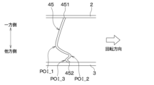
- the trailing edge 45 has four inflection points POI_1, POI_2, POI_3, and POI_4.
- the portions connecting the four inflection points POI_1, POI_2, POI_3, and POI_4 are linear.
- the configuration of the fourth embodiment is such that the rear edge 45 is temporarily provided in parallel to the axis CL, depending on the pressure loss body disposed on the upstream side of the centrifugal fan 1 and the shape or physique of each component of the centrifugal fan 1. This is effective in cases where variations occur in the wind speed distribution in each area of the blade outlet 44.
- the pressure loss body refers to an object that causes a pressure loss in airflow, such as a case of a blower in which the centrifugal fan 1 is installed, or a filter installed on the upstream side of the centrifugal fan 1.
- the exit angle of the portion of the trailing edge 45 that corresponds to a region where the wind speed is slow is made small, and the exit angle of a portion of the trailing edge 45 that corresponds to a region where the wind speed is fast is made large.
- the exit angle it is possible to increase the amount of work from the blades 4 to the air and increase the wind speed relative to other parts.
- by increasing the exit angle it is possible to reduce the amount of work from the blades 4 to the air, and to lower the wind speed relatively compared to other parts.
- the centrifugal fan 1 of the fourth embodiment can also reduce noise and increase air blowing efficiency.
- the trailing edge 45 has three inflection points POI_1, POI_2, and POI_3.
- the portions connecting the three inflection points POI_1, POI_2, and POI_3 are curved.
- the configuration of the fifth embodiment also has a configuration in which, if the trailing edge 45 is provided parallel to the axis CL and the wind speed distribution in each area of the blade outlet 44 varies, the wind speed distribution blown out from the blade outlet 44 is It is possible to make it close to uniform. Therefore, the centrifugal fan 1 of the fifth embodiment can also reduce noise and increase air blowing efficiency.
- the trailing edge 45 has four inflection points POI_1, POI_2, POI_3, and POI_4.
- the portions connecting the four inflection points POI_1, POI_2, POI_3, and POI_4 are curved.
- the configuration of the sixth embodiment also has a configuration in which, if the trailing edge 45 is provided parallel to the axis CL and the wind speed distribution in each area of the blade outlet 44 varies, the wind speed distribution blown out from the blade outlet 44 It is possible to make it close to uniform. Therefore, the centrifugal fan 1 of the sixth embodiment can also reduce noise and increase air blowing efficiency.
- the seventh to eleventh embodiments are the same as the first embodiment, etc., except that the shape of the trailing edge 45 of the blade 4 as seen from the rotation direction is changed. Therefore, only the parts that are different from the first embodiment etc. will be explained. Note that the configurations of the seventh to eleventh embodiments and the configurations described in the first to sixth embodiments can be arbitrarily combined.
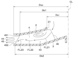
- a distance Db2 between a portion 452 of the trailing edge 45 that connects to the main plate 3 and the axis CL is a distance Db2 between a portion 451 of the trailing edge 45 that connects to the shroud 2 and the axis CL. It is farther than the distance Db1 from CL.
- the rear edge 45 is formed in a straight line so that the distance from the axis CL gradually decreases from a portion 452 connected to the main plate 3 to a portion 451 connected to the shroud 2.
- the air flow in the inter-blade flow path 43 separates from the shroud 2 near the leading edge 46 and is temporarily biased towards the main plate 3, but then, as shown by the arrow FL22, the air flow in the inter-blade flow path 43
- the water flows so as to re-adhere to the shroud 2 in the middle of the interflow path 43. Therefore, at the blade outlet 44, the airflow may be biased toward the shroud 2 side, and a velocity distribution of the airflow may be biased in the axial direction.
- the centrifugal fan 1 of the seventh embodiment increases the amount of work applied to the air from the main plate 3 side of the blade 4, so that the area near the blade outlet 44 in the inter-blade flow path 43 is increased, as shown by arrow FL23. It is possible to draw the air flow toward the main plate 3 side again. As a result, compared to the case where the trailing edge 45 is provided parallel to the axis CL, the speed distribution of the air blown out from the blade outlet 44 is made closer to uniformity, thereby reducing noise and increasing the air blowing efficiency. I can do it.
- the configuration of the centrifugal fan 1 of the seventh embodiment satisfies the relationship 0.5 ⁇ Dsi/Dso ⁇ 0.7, where the inner diameter of the shroud 2 is Dsi and the outer diameter of the shroud 2 is Dso. , is more effective. This is due to the following reason.
- Dsi/Dso is 0.5 or less, a sufficiently long length of the inter-blade flow path 43 through which air flows after the air flow is biased toward the shroud 2 side is ensured. In that case, even if the shape of the trailing edge 45 when viewed from the rotation direction is parallel to the axis CL, after the airflow is biased towards the shroud 2 side, by the time it reaches the trailing edge 45, the bias of the airflow is eased. On the other hand, if Dsi/Dso is 0.7 or more, the air flow in the interblade flow path 43 reaches the trailing edge 45 before being biased so as to reattach to the shroud 2 side.
- the air flow indicated by arrows FL21 and FL22 is cut off in the middle. Therefore, in order to utilize the configuration of the centrifugal fan 1 of the seventh embodiment more effectively, it is preferable to satisfy the relationship 0.5 ⁇ Dsi/Dso ⁇ 0.7.
- the distance Db2 between the portion 452 of the trailing edge 45 that connects to the main plate 3 and the axis CL is the same as the distance Db2 between the portion 451 of the trailing edge 45 that connects to the shroud 2 and the axis CL. It is configured to be farther than the distance Db1 from CL. Thereby, the amount of work applied to the air from the portion of the blade 4 on the main plate 3 side can be increased, and the air flow near the blade outlet 44 in the inter-blade flow path 43 can be drawn toward the main plate 3 side again.
- the speed distribution of the air blown out from the blade outlet 44 is made closer to uniformity, thereby reducing noise and increasing the air blowing efficiency. I can do it.
- the distance Db2 between the portion 452 of the trailing edge 45 that connects to the main plate 3 and the axis CL is such that the distance Db2 of the trailing edge 45 that connects to the shroud 2
- the distance between the portion 451 and the axis CL is longer than the distance Db1. Therefore, since the centrifugal fans 1 of the eighth to eleventh embodiments have the same configuration as the seventh embodiment described above, it is possible to achieve the same effects as the centrifugal fan 1 of the seventh embodiment.
- the trailing edge 45 has a step shape in which the distance from the axis CL gradually decreases from a portion 452 connected to the main plate 3 to a portion 451 connected to the shroud 2. It becomes.
- the trailing edge 45 includes a first trailing edge 45a, a second trailing edge 45b, and a third trailing edge 45c.
- the first rear edge portion 45a is a portion extending from the main plate 3 toward the shroud 2 along the axial direction.
- the second rear edge portion 45b is a portion of the first rear edge portion 45a that extends from the end on the shroud 2 side toward the axis CL side.
- the third rear edge portion 45c is a portion of the second rear edge portion 45b that extends from the end on the axis CL side toward the shroud 2 along the axial direction. Therefore, in the eighth embodiment, it has a stepped shape having two corner portions 45s and 45t and three straight portions (ie, the first to third rear edge portions 45a to 45c).
- the centrifugal fan 1 of the eighth embodiment described above can also have the same effects as the seventh embodiment.
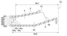
- the trailing edge 45 has a step shape in which the distance from the axis CL gradually decreases from a portion 452 connected to the main plate 3 to a portion 451 connected to the shroud 2. It becomes.
- the trailing edge 45 includes a first trailing edge 45a, a second trailing edge 45b, a third trailing edge 45c, a fourth trailing edge 45d, and a fifth trailing edge 45e. are doing.
- the first rear edge portion 45a is a portion extending from the main plate 3 toward the shroud 2 along the axial direction.
- the second rear edge portion 45b is a portion of the first rear edge portion 45a that extends from the end on the shroud 2 side toward the axis CL side.
- the third rear edge portion 45c is a portion of the second rear edge portion 45b that extends from the end on the axis CL side toward the shroud 2 along the axial direction.
- the fourth rear edge portion 45d is a portion of the third rear edge portion 45c that extends from the end on the shroud 2 side toward the axis CL side.
- the fifth rear edge portion 45e is a portion of the fourth rear edge portion 45d that extends from the end on the axis CL side toward the shroud 2 along the axial direction. Therefore, in the ninth embodiment, the stepped shape has four corner portions 45s to 45v and five straight portions (ie, first to fifth rear edge portions 45a to 45e).
- the centrifugal fan 1 of the ninth embodiment described above can also have the same effects as the seventh and eighth embodiments. Note that the number of corners and the number of straight parts of the stepped shape formed on the rear edge 45 can be set arbitrarily.
- the rear edge 45 has an inclined portion 45f and a straight portion 45g.
- the inclined portion 45f is a portion formed linearly from the portion 452 connected to the main plate 3 toward the central portion 453 in the axial direction so that the distance to the axial center CL gradually becomes shorter.
- the straight portion 45g is a portion formed parallel to the axis CL from the center portion 453 in the axial direction to the portion 451 connected to the shroud 2.
- centrifugal fan 1 of the tenth embodiment described above can also provide the same effects as the seventh to ninth embodiments.
- the trailing edge 45 has a curved shape from a portion 452 connected to the main plate 3 to a portion 451 connected to the shroud 2, so that the distance to the axis CL gradually becomes shorter. is formed.
- the shape of the curve can be set arbitrarily.
- the centrifugal fan 1 of the eleventh embodiment described above can also achieve the same effects as the seventh to tenth embodiments.
- the centrifugal fan 1 has been described as a turbo fan, but it is not limited thereto, and may be of other types, such as a radial fan.
- the present disclosure is not limited to the embodiments described above, and can be modified as appropriate. Furthermore, the embodiments described above are not unrelated to each other, and can be combined as appropriate, except in cases where combination is clearly impossible. Furthermore, in each of the above embodiments, it goes without saying that the elements constituting the embodiments are not necessarily essential, except in cases where it is specifically stated that they are essential or where they are clearly considered essential in principle. stomach. In addition, in each of the above embodiments, when numerical values such as the number, numerical value, amount, range, etc. of the constituent elements of the embodiment are mentioned, it is particularly specified that they are essential, or it is clearly limited to a specific number in principle. It is not limited to that specific number, except in cases where In addition, in each of the above embodiments, when referring to the shape, positional relationship, etc. of constituent elements, etc., the shape, It is not limited to positional relationships, etc.
Landscapes
- Engineering & Computer Science (AREA)
- Mechanical Engineering (AREA)
- General Engineering & Computer Science (AREA)
- Structures Of Non-Positive Displacement Pumps (AREA)
Priority Applications (3)
| Application Number | Priority Date | Filing Date | Title |
|---|---|---|---|
| CN202380033155.2A CN119013477A (zh) | 2022-04-12 | 2023-03-24 | 离心风扇 |
| DE112023001908.8T DE112023001908T5 (de) | 2022-04-12 | 2023-03-24 | Zentrifugalventilator |
| US18/810,890 US12584486B2 (en) | 2022-04-12 | 2024-08-21 | Centrifugal fan |
Applications Claiming Priority (2)
| Application Number | Priority Date | Filing Date | Title |
|---|---|---|---|
| JP2022065872A JP7815956B2 (ja) | 2022-04-12 | 2022-04-12 | 遠心ファン |
| JP2022-065872 | 2022-04-12 |
Related Child Applications (1)
| Application Number | Title | Priority Date | Filing Date |
|---|---|---|---|
| US18/810,890 Continuation US12584486B2 (en) | 2022-04-12 | 2024-08-21 | Centrifugal fan |
Publications (1)
| Publication Number | Publication Date |
|---|---|
| WO2023199731A1 true WO2023199731A1 (ja) | 2023-10-19 |
Family
ID=88329470
Family Applications (1)
| Application Number | Title | Priority Date | Filing Date |
|---|---|---|---|
| PCT/JP2023/011994 Ceased WO2023199731A1 (ja) | 2022-04-12 | 2023-03-24 | 遠心ファン |
Country Status (5)
| Country | Link |
|---|---|
| US (1) | US12584486B2 (https=) |
| JP (1) | JP7815956B2 (https=) |
| CN (1) | CN119013477A (https=) |
| DE (1) | DE112023001908T5 (https=) |
| WO (1) | WO2023199731A1 (https=) |
Families Citing this family (2)
| Publication number | Priority date | Publication date | Assignee | Title |
|---|---|---|---|---|
| JP7697401B2 (ja) * | 2022-04-21 | 2025-06-24 | 株式会社デンソー | 送風機 |
| DE102024123702B3 (de) | 2024-08-20 | 2025-11-13 | Ebm-Papst Mulfingen Gmbh & Co. Kg | Laufrad für einen Ventilator |
Citations (5)
| Publication number | Priority date | Publication date | Assignee | Title |
|---|---|---|---|---|
| WO2009128299A1 (ja) * | 2008-04-18 | 2009-10-22 | 三菱電機株式会社 | ターボファンおよび空気調和機 |
| JP2009281215A (ja) * | 2008-05-21 | 2009-12-03 | Daikin Ind Ltd | 空気調和機用室内機 |
| JP2011064072A (ja) * | 2009-09-15 | 2011-03-31 | Mitsubishi Electric Corp | ファン、そのファンを備えた電動送風機及び、その電動送風機を用いた電気掃除機 |
| JP2011226448A (ja) * | 2010-04-23 | 2011-11-10 | Toshiba Carrier Corp | 遠心ファン及び空気調和機 |
| CN110836193A (zh) * | 2019-12-19 | 2020-02-25 | 湖南联诚轨道装备有限公司 | 一种非对称式离心叶轮风机 |
Family Cites Families (8)
| Publication number | Priority date | Publication date | Assignee | Title |
|---|---|---|---|---|
| JP2007170771A (ja) | 2005-12-26 | 2007-07-05 | Daikin Ind Ltd | ターボファン及びこれを用いた空気調和機の室内ユニット |
| JP4396775B2 (ja) * | 2007-11-26 | 2010-01-13 | ダイキン工業株式会社 | 遠心ファン |
| KR101486550B1 (ko) * | 2010-11-16 | 2015-01-23 | 삼성전자 주식회사 | 송풍용 원심팬 및 이를 갖는 냉장고 |
| KR101645178B1 (ko) * | 2013-05-10 | 2016-08-03 | 엘지전자 주식회사 | 원심팬 및 원심팬의 제조방법 |
| EP2829733B1 (en) * | 2013-05-10 | 2021-01-27 | Lg Electronics Inc. | Centrifugal fan |
| JP6981077B2 (ja) | 2017-07-27 | 2021-12-15 | 株式会社デンソー | 遠心ファン |
| EP3896290B1 (en) * | 2018-12-13 | 2023-03-29 | Mitsubishi Electric Corporation | Centrifugal fan and air conditioner |
| JP2022065872A (ja) | 2020-10-16 | 2022-04-28 | 株式会社デンソー | 超音波センサ |
-
2022
- 2022-04-12 JP JP2022065872A patent/JP7815956B2/ja active Active
-
2023
- 2023-03-24 WO PCT/JP2023/011994 patent/WO2023199731A1/ja not_active Ceased
- 2023-03-24 DE DE112023001908.8T patent/DE112023001908T5/de active Pending
- 2023-03-24 CN CN202380033155.2A patent/CN119013477A/zh active Pending
-
2024
- 2024-08-21 US US18/810,890 patent/US12584486B2/en active Active
Patent Citations (5)
| Publication number | Priority date | Publication date | Assignee | Title |
|---|---|---|---|---|
| WO2009128299A1 (ja) * | 2008-04-18 | 2009-10-22 | 三菱電機株式会社 | ターボファンおよび空気調和機 |
| JP2009281215A (ja) * | 2008-05-21 | 2009-12-03 | Daikin Ind Ltd | 空気調和機用室内機 |
| JP2011064072A (ja) * | 2009-09-15 | 2011-03-31 | Mitsubishi Electric Corp | ファン、そのファンを備えた電動送風機及び、その電動送風機を用いた電気掃除機 |
| JP2011226448A (ja) * | 2010-04-23 | 2011-11-10 | Toshiba Carrier Corp | 遠心ファン及び空気調和機 |
| CN110836193A (zh) * | 2019-12-19 | 2020-02-25 | 湖南联诚轨道装备有限公司 | 一种非对称式离心叶轮风机 |
Also Published As
| Publication number | Publication date |
|---|---|
| CN119013477A (zh) | 2024-11-22 |
| DE112023001908T5 (de) | 2025-03-13 |
| JP7815956B2 (ja) | 2026-02-18 |
| US12584486B2 (en) | 2026-03-24 |
| US20240410375A1 (en) | 2024-12-12 |
| JP2023156170A (ja) | 2023-10-24 |
Similar Documents
| Publication | Publication Date | Title |
|---|---|---|
| JP4994421B2 (ja) | 遠心ファン及び空気調和機 | |
| CN107795516B (zh) | 轴流风扇及室外机 | |
| CN104822945B (zh) | 离心风扇 | |
| JP7003337B1 (ja) | ターボファン及び空気調和機 | |
| CN101203680B (zh) | 轴流风扇 | |
| WO2023199731A1 (ja) | 遠心ファン | |
| JP3677214B2 (ja) | 軸流ファン | |
| CN110914553A (zh) | 叶轮、送风机及空调装置 | |
| JP4115180B2 (ja) | 羽根車および遠心圧縮機 | |
| JP4818310B2 (ja) | 軸流送風機 | |
| CN118715376A (zh) | 叶轮、送风机及空气调节机 | |
| JP2001159396A (ja) | 遠心ファン及び該遠心ファンを備えた空気調和機 | |
| CN110939603A (zh) | 叶片及使用其的轴流叶轮 | |
| JP2019127865A (ja) | 遠心ファン | |
| JP2003180051A (ja) | 全閉外扇形回転電機の回転羽根 | |
| JP7413973B2 (ja) | 送風機 | |
| KR20040026882A (ko) | 축류팬 | |
| JP7409246B2 (ja) | ターボファン | |
| JP2019027327A (ja) | 遠心ファン | |
| JP7697401B2 (ja) | 送風機 | |
| JP6038320B2 (ja) | 多翼送風機 | |
| KR102782040B1 (ko) | 횡류팬 | |
| JPWO2020110257A1 (ja) | タービン動翼及びタービン | |
| JP6625291B1 (ja) | 羽根車、送風機及び空気調和機 | |
| JP6038321B2 (ja) | 多翼送風機 |
Legal Events
| Date | Code | Title | Description |
|---|---|---|---|
| 121 | Ep: the epo has been informed by wipo that ep was designated in this application |
Ref document number: 23788151 Country of ref document: EP Kind code of ref document: A1 |
|
| WWE | Wipo information: entry into national phase |
Ref document number: 202380033155.2 Country of ref document: CN |
|
| WWE | Wipo information: entry into national phase |
Ref document number: 112023001908 Country of ref document: DE |
|
| WWP | Wipo information: published in national office |
Ref document number: 112023001908 Country of ref document: DE |
|
| 122 | Ep: pct application non-entry in european phase |
Ref document number: 23788151 Country of ref document: EP Kind code of ref document: A1 |