WO2023199683A1 - 吸収性パッド - Google Patents
吸収性パッド Download PDFInfo
- Publication number
- WO2023199683A1 WO2023199683A1 PCT/JP2023/009776 JP2023009776W WO2023199683A1 WO 2023199683 A1 WO2023199683 A1 WO 2023199683A1 JP 2023009776 W JP2023009776 W JP 2023009776W WO 2023199683 A1 WO2023199683 A1 WO 2023199683A1
- Authority
- WO
- WIPO (PCT)
- Prior art keywords
- absorbent pad
- pad
- absorbent
- width direction
- skin
- Prior art date
- Legal status (The legal status is an assumption and is not a legal conclusion. Google has not performed a legal analysis and makes no representation as to the accuracy of the status listed.)
- Ceased
Links
Images

Classifications
-
- A—HUMAN NECESSITIES
- A61—MEDICAL OR VETERINARY SCIENCE; HYGIENE
- A61F—FILTERS IMPLANTABLE INTO BLOOD VESSELS; PROSTHESES; DEVICES PROVIDING PATENCY TO, OR PREVENTING COLLAPSING OF, TUBULAR STRUCTURES OF THE BODY, e.g. STENTS; ORTHOPAEDIC, NURSING OR CONTRACEPTIVE DEVICES; FOMENTATION; TREATMENT OR PROTECTION OF EYES OR EARS; BANDAGES, DRESSINGS OR ABSORBENT PADS; FIRST-AID KITS
- A61F13/00—Bandages or dressings; Absorbent pads
- A61F13/15—Absorbent pads, e.g. sanitary towels, swabs or tampons for external or internal application to the body; Supporting or fastening means therefor; Tampon applicators
- A61F13/45—Absorbent pads, e.g. sanitary towels, swabs or tampons for external or internal application to the body; Supporting or fastening means therefor; Tampon applicators characterised by the shape
- A61F13/47—Sanitary towels, incontinence pads or napkins
-
- A—HUMAN NECESSITIES
- A61—MEDICAL OR VETERINARY SCIENCE; HYGIENE
- A61F—FILTERS IMPLANTABLE INTO BLOOD VESSELS; PROSTHESES; DEVICES PROVIDING PATENCY TO, OR PREVENTING COLLAPSING OF, TUBULAR STRUCTURES OF THE BODY, e.g. STENTS; ORTHOPAEDIC, NURSING OR CONTRACEPTIVE DEVICES; FOMENTATION; TREATMENT OR PROTECTION OF EYES OR EARS; BANDAGES, DRESSINGS OR ABSORBENT PADS; FIRST-AID KITS
- A61F13/00—Bandages or dressings; Absorbent pads
- A61F13/15—Absorbent pads, e.g. sanitary towels, swabs or tampons for external or internal application to the body; Supporting or fastening means therefor; Tampon applicators
- A61F13/45—Absorbent pads, e.g. sanitary towels, swabs or tampons for external or internal application to the body; Supporting or fastening means therefor; Tampon applicators characterised by the shape
- A61F13/49—Absorbent pads, e.g. sanitary towels, swabs or tampons for external or internal application to the body; Supporting or fastening means therefor; Tampon applicators characterised by the shape specially adapted to be worn around the waist, e.g. diapers or nappies
- A61F13/494—Absorbent pads, e.g. sanitary towels, swabs or tampons for external or internal application to the body; Supporting or fastening means therefor; Tampon applicators characterised by the shape specially adapted to be worn around the waist, e.g. diapers or nappies characterised by edge leakage prevention means
-
- A—HUMAN NECESSITIES
- A61—MEDICAL OR VETERINARY SCIENCE; HYGIENE
- A61F—FILTERS IMPLANTABLE INTO BLOOD VESSELS; PROSTHESES; DEVICES PROVIDING PATENCY TO, OR PREVENTING COLLAPSING OF, TUBULAR STRUCTURES OF THE BODY, e.g. STENTS; ORTHOPAEDIC, NURSING OR CONTRACEPTIVE DEVICES; FOMENTATION; TREATMENT OR PROTECTION OF EYES OR EARS; BANDAGES, DRESSINGS OR ABSORBENT PADS; FIRST-AID KITS
- A61F13/00—Bandages or dressings; Absorbent pads
- A61F13/15—Absorbent pads, e.g. sanitary towels, swabs or tampons for external or internal application to the body; Supporting or fastening means therefor; Tampon applicators
- A61F13/45—Absorbent pads, e.g. sanitary towels, swabs or tampons for external or internal application to the body; Supporting or fastening means therefor; Tampon applicators characterised by the shape
- A61F13/49—Absorbent pads, e.g. sanitary towels, swabs or tampons for external or internal application to the body; Supporting or fastening means therefor; Tampon applicators characterised by the shape specially adapted to be worn around the waist, e.g. diapers or nappies
- A61F13/496—Absorbent pads, e.g. sanitary towels, swabs or tampons for external or internal application to the body; Supporting or fastening means therefor; Tampon applicators characterised by the shape specially adapted to be worn around the waist, e.g. diapers or nappies in the form of pants or briefs
-
- A—HUMAN NECESSITIES
- A61—MEDICAL OR VETERINARY SCIENCE; HYGIENE
- A61F—FILTERS IMPLANTABLE INTO BLOOD VESSELS; PROSTHESES; DEVICES PROVIDING PATENCY TO, OR PREVENTING COLLAPSING OF, TUBULAR STRUCTURES OF THE BODY, e.g. STENTS; ORTHOPAEDIC, NURSING OR CONTRACEPTIVE DEVICES; FOMENTATION; TREATMENT OR PROTECTION OF EYES OR EARS; BANDAGES, DRESSINGS OR ABSORBENT PADS; FIRST-AID KITS
- A61F13/00—Bandages or dressings; Absorbent pads
- A61F13/15—Absorbent pads, e.g. sanitary towels, swabs or tampons for external or internal application to the body; Supporting or fastening means therefor; Tampon applicators
- A61F13/505—Absorbent pads, e.g. sanitary towels, swabs or tampons for external or internal application to the body; Supporting or fastening means therefor; Tampon applicators with separable parts, e.g. combination of disposable and reusable parts
-
- A—HUMAN NECESSITIES
- A61—MEDICAL OR VETERINARY SCIENCE; HYGIENE
- A61F—FILTERS IMPLANTABLE INTO BLOOD VESSELS; PROSTHESES; DEVICES PROVIDING PATENCY TO, OR PREVENTING COLLAPSING OF, TUBULAR STRUCTURES OF THE BODY, e.g. STENTS; ORTHOPAEDIC, NURSING OR CONTRACEPTIVE DEVICES; FOMENTATION; TREATMENT OR PROTECTION OF EYES OR EARS; BANDAGES, DRESSINGS OR ABSORBENT PADS; FIRST-AID KITS
- A61F13/00—Bandages or dressings; Absorbent pads
- A61F13/15—Absorbent pads, e.g. sanitary towels, swabs or tampons for external or internal application to the body; Supporting or fastening means therefor; Tampon applicators
- A61F13/53—Absorbent pads, e.g. sanitary towels, swabs or tampons for external or internal application to the body; Supporting or fastening means therefor; Tampon applicators characterised by the absorbing medium
-
- A—HUMAN NECESSITIES
- A61—MEDICAL OR VETERINARY SCIENCE; HYGIENE
- A61F—FILTERS IMPLANTABLE INTO BLOOD VESSELS; PROSTHESES; DEVICES PROVIDING PATENCY TO, OR PREVENTING COLLAPSING OF, TUBULAR STRUCTURES OF THE BODY, e.g. STENTS; ORTHOPAEDIC, NURSING OR CONTRACEPTIVE DEVICES; FOMENTATION; TREATMENT OR PROTECTION OF EYES OR EARS; BANDAGES, DRESSINGS OR ABSORBENT PADS; FIRST-AID KITS
- A61F13/00—Bandages or dressings; Absorbent pads
- A61F13/15—Absorbent pads, e.g. sanitary towels, swabs or tampons for external or internal application to the body; Supporting or fastening means therefor; Tampon applicators
- A61F13/84—Accessories, not otherwise provided for, for absorbent pads
Definitions
- the present invention relates to an absorbent pad.
- Absorbent pads that are attached to the inside of disposable diapers are known.
- a pair of low basis weight regions along the longitudinal direction are provided in the central region of the absorber in the longitudinal direction. Therefore, while the absorbent pad is being worn, the low basis weight region serves as a bending point, and the cross section along the width direction deforms into a W-shape, making it easier to fit the wearer's crotch region.
- regions having lower rigidity than the central region are provided before and after the central region in the longitudinal direction of the absorbent pad. Therefore, the low-rigidity region of the absorbent pad serves as a bending point, and the cross section along the longitudinal direction also deforms into a W-shape, making it easier to follow the roundness of the body.
- Pants-type diapers have a good fit and are easy for the wearer to carry out activities, so people who need to wear pants-type diapers include people who require minor care and people who lead normal daily lives.
- a pants-type diaper outside the home it is difficult to remove pants, shoes, etc. Therefore, by layering an absorbent pad like the one disclosed in Patent Document 1 on the inside of a pants-type diaper and replacing only the absorbent pad, the pants-type diaper can be used for a long period of time, and the number of times the pants-type diaper is changed can be reduced. can be reduced.
- the absorbent pad in order to attach a new absorbent pad to the inside of the diaper while the pants or pants-type diaper are down to the wearer's knees without being removed, the absorbent pad must be inserted through the diaper's narrow girth opening. No. Generally, it is considered that an absorbent pad is folded in half in the longitudinal direction and the pad is inserted into the inside of a diaper along the longitudinal direction. The same applies when an absorbent pad is attached directly to underwear (pants or shorts).
- the present invention has been made in view of the above-mentioned problems, and aims to provide an absorbent pad that is easy to attach to pants-type disposable diapers and underwear, and that reduces discomfort during wear. purpose.
- the main invention for achieving the above object is to provide an absorbent material having longitudinal direction, width direction, and thickness direction in an unfolded state, and having an absorbent core, a skin-side sheet, and a non-skin-side sheet.
- the skin-side sheet is located closest to the skin of the absorbent pad
- the non-skin-side sheet is located at the center of the absorbent pad in the longitudinal direction and the width direction. It is located on the most non-skin side of the absorbent pad, and when the absorbent pad is unfolded and stretched, the maximum thickness from the skin side of the skin side sheet to the non-skin side of the non-skin side sheet is 4.
- an absorbent pad that is easy to attach to pants-type disposable diapers or underwear, and reduces discomfort during wear.
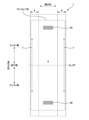
- FIG. 2 is a plan view of the absorbent pad 1 in an expanded and stretched state, viewed from the skin side.
- FIG. 2 is a plan view of the absorbent pad 1 in an expanded and stretched state, viewed from the non-skin side.
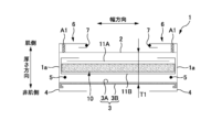
- 2 is a schematic cross-sectional view of the absorbent pad 1 along the center line CL in FIG. 1.
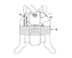
- FIG. FIG. 3 is a diagram showing how the pad 1 is inserted into the pants-type diaper 40.
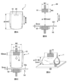
- 5A to 5D are explanatory diagrams of a pad compression test.
- FIG. 3 is an explanatory diagram of the arrangement of the joining member 20 and the pressing part 30.
- FIG. 3 is an explanatory diagram of the arrangement of the joining member 20 and the pressing part 30.
- FIG. 3 is an explanatory diagram of the maximum thickness T1 of the pad 1.
- FIG. 3 is an explanatory diagram of the maximum thickness T1 of the pad 1.
- An absorbent pad having a longitudinal direction, a width direction, and a thickness direction in an unfolded state, and having an absorbent core, a skin-side sheet, and a non-skin-side sheet, the absorbent pad comprising: In the central portions of the longitudinal direction and the width direction, the skin-side sheet is located closest to the skin of the absorbent pad, and the non-skin-side sheet is located closest to the skin of the absorbent pad.
- the maximum thickness from the skin side of the skin side sheet to the non-skin side of the non-skin side sheet is 4.0 mm or less, and the thickness is 4.0 mm or less when folded along the width direction.
- Absorbency characterized by a maximum load of 1.0 N or more in a pad compression test in which the crotch side end of the absorbent pad folded in half is pressed against a test stand to compress the absorbent pad. pad.
- Such an absorbent pad has high rigidity in the longitudinal direction when folded in half, so when inserting the absorbent pad into an outer layer such as a pants-type diaper or underwear, it is difficult to bend and can be inserted smoothly. Easy to attach to outerwear.
- the maximum thickness T1 of the absorbent pad is less than 4.0 mm, which reduces discomfort when worn even when worn over outerwear. .
- the maximum length of the absorbent pad in the longitudinal direction is 600 mm or less, and the maximum width of the absorbent pad in the width direction is 600 mm or less.
- the planar size is small, it is easy to insert the absorbent pad through the narrow waist opening of the outer.
- the absorbent pad has a small planar size, it has high rigidity in the longitudinal direction when folded in half, so when inserting the absorbent pad into the outer layer, it is difficult to bend and can be inserted smoothly.
- the absorbent pad has a small planar size, it reduces discomfort even when worn over outerwear.
- This absorbent pad is characterized in that the absorbent core is not constricted inward in the width direction in the central portion of the absorbent pad in the longitudinal direction including the folding position.
- the width of the absorbent core becomes longer at the folded part of the absorbent pad, so when inserting the absorbent pad into the outer layer, the force applied to the absorbent core is distributed across the width. Therefore, the absorbent pad is difficult to bend, and the absorbent pad can be smoothly inserted into the outer layer.
- This absorbent pad is characterized in that the absorbent core has a compressed portion where the absorbent core is compressed in the thickness direction.
- the stiffness of the absorbent pad is increased by the compressed portion, so that the maximum load in the pad compression test can be 1.0 N or more. Furthermore, the maximum thickness of the absorbent pad can be reduced to 4.0 mm or less while maintaining absorption performance.
- Such an absorbent pad is characterized in that the compressed portion has a pair of longitudinal compressed portions extending longer in the longitudinal direction than in the width direction on both sides of the absorbent core in the width direction. absorbent pad.
- the longitudinal rigidity of the absorbent pad in a folded state can be increased, and when inserting the absorbent pad into the outer layer, the absorbent pad is difficult to bend and can be inserted smoothly. I can do it.
- the longitudinal compressed portion serves as a starting point for folding, making it easier for both sides of the absorbent pad in the width direction to stand up toward the skin and to easily follow the wearer's crotch area, thereby reducing discomfort during wear.
- a bonding member for bonding the absorbent pad to an outer is provided on a non-skin side of the absorbent pad, and the bonding member is configured to connect the absorbent pad to the outer surface of the absorbent pad.
- An absorbent pad characterized by being located on the inside in the width direction.
- a bonding member for bonding the absorbent pad to an outer is provided on the non-skin side of the absorbent pad, and the absorbent pad is connected three times in the width direction with its maximum width.
- the length of the joining member in the width direction is shortened, so when inserting the absorbent pad into the outerwear, the wide part of the joining member can be covered by the wearer's hand.
- the absorbent pad has a pair of leg circumferences provided along the longitudinal direction such that the absorbent pad extends around the wearer's legs on both sides in the width direction.
- An absorbent pad comprising at least one of an elastic member and a pair of leak-proof wall elastic members provided along the longitudinal direction so that the leak-proof wall portion stands up on the skin side. .
- both sides of the absorbent core in the width direction contract in the longitudinal direction, increasing rigidity. Therefore, when inserting the absorbent pad into the outer layer, the absorbent pad is not easily bent, and the absorbent pad can be inserted smoothly.
- the absorbent pad is a sheet forming a side edge in the width direction of the absorbent pad, and the absorbent pad is a sheet that forms the side edge of the absorbent pad in the width direction, and the absorbent pad is formed from the side edge of the absorbent core in the non-skin side.
- An absorbent pad comprising a sheet that is folded back inward in the width direction toward the skin side from the absorbent core so as to wrap around the side edges in the width direction.
- the absorbent core can be arranged over almost the entire width of the absorbent pad, and the rigidity can be increased over almost the entire width of the absorbent pad. Further, by folding the sheet, the number of laminated materials on the sides of the absorbent pad in the width direction increases, and the rigidity of the sides of the absorbent pad in the width direction increases. Therefore, when inserting the absorbent pad into the outer layer, the absorbent pad is not easily bent, and the absorbent pad can be inserted smoothly.
- a pair of sheets are provided on both sides of the absorbent pad in the width direction, and the pair of sheets are spaced apart in the width direction on a non-skin side surface of the absorbent pad.
- the absorbent core is a compressed part in which the absorbent core is compressed in the thickness direction, and the absorbent core is compressed in the thickness direction, and the absorbent core is compressed in the width direction on both sides of the absorbent core in the width direction.
- the absorbent pad has a pair of longitudinally compressed parts extending in the longitudinal direction, and the longitudinally compressed parts are located on the non-skin side of the absorbent pad on the inner side of the sheet in the width direction. absorbent pad.
- a bonding member for bonding the absorbent pad to an outer layer is provided on a non-skin side surface of the absorbent pad, and the absorbent core has a thickness of
- the absorbent pad has a pair of longitudinally compressed portions which are compressed in the direction, and which extend longer in the longitudinal direction than in the widthwise direction on both sides of the width direction of the absorbent core.
- An absorbent pad characterized in that the longitudinal compressed portion is provided closer to the crotch than the outer end of the joining member in the longitudinal direction in the expanded and stretched state.
- the joining member is provided in a region of the absorbent pad that is easily bent, which is outside the longitudinally compressed portion in the longitudinal direction. Therefore, the easily bendable region of the absorbent pad is firmly joined to the outer layer by the joining member, and it is possible to suppress the occurrence of unintentional bending while wearing the absorbent pad, and to reduce discomfort while wearing the absorbent pad.
- the absorbent pad has a liquid-impermeable leak-proof layer on the non-skin side of the absorbent core, and the non-skin side surface of the non-skin side sheet has a leak-proof layer on the non-skin side of the absorbent core.
- the non-skin side of the absorbent pad becomes difficult to slip against the inner side of the outer, and it is possible to suppress misalignment of the absorbent pad with respect to the outer while wearing, and to reduce discomfort.
- the absorbent pad according to the present invention an absorbent pad that is placed inside a pants-type disposable diaper for adults and used in combination with the diaper will be exemplified.
- the absorbent pad according to the present invention can be used as a single absorbent pad by directly placing it inside the wearer's underwear (pants or shorts). It can also be used by placing it inside tape-type disposable diapers or children's disposable diapers.
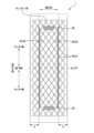
- FIG. 1 is a plan view of the absorbent pad 1 in an expanded and stretched state, viewed from the skin side.
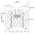
- FIG. 2 is a plan view of the absorbent pad 1 in an expanded and stretched state, viewed from the non-skin side.
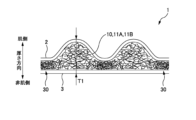
- FIG. 3 is a schematic cross-sectional view of the absorbent pad 1 along the center line CL in FIG.
- the absorbent pad 1 (hereinafter also simply referred to as "pad”) has a rectangular planar shape in the unfolded state, and has a longitudinal direction, a width direction, and a thickness direction that are orthogonal to each other.
- the longitudinal direction is along the front-rear direction from the ventral side to the dorsal side of the wearer when the pad 1 is worn.
- the side that contacts the wearer's skin is referred to as the skin side or skin side
- the opposite side is referred to as the non-skin side or non-skin side. Since the pad 1 of this embodiment has a symmetrical configuration in the longitudinal direction, either side of the pad 1 in the longitudinal direction may correspond to the ventral side of the wearer.
- the pad 1 is worn without being connected at one end and the other end in the longitudinal direction along the wearer's waist.
- the unfolded state of the pad 1 refers to the state in which the entire pad 1 is unfolded in a two-dimensional manner.
- the stretched state of the pad 1 is a state in which the pad 1 is stretched to such an extent that wrinkles that have occurred on the pad 1 are virtually no longer visible, and the dimensions of each member constituting the pad 1 (for example, the side sheet 4 described later) are The pad 1 is in an extended state until it reaches a length that matches or is close to the dimensions of the single member.
- the pad 1 includes an absorbent core 10, a liquid-permeable skin-side sheet 2 (for example, nonwoven fabric, etc.) provided closer to the skin than the absorbent core 10, and It has a non-skin side sheet 3 provided on the non-skin side and a pair of side sheets 4 provided on both sides of the pad 1 in the width direction.
- the non-skin side sheet 3 of this embodiment has a two-layer structure in which a non-woven fabric is laminated from the non-skin side to a liquid-impermeable resin film such as polyethylene or polypropylene.
- the pair of side sheets 4 are folded inward in the width direction from the non-skin side surface of the non-skin side sheet 3 toward the skin side surface of the skin side sheet 2 so as to wrap around the absorbent core 10.
- An example of the absorbent core 10 is one in which liquid absorbent fibers such as pulp fibers containing SAP (super absorbent polymer) are molded into a predetermined shape.
- the absorbent core 10 illustrated in FIG. 3 has its skin side covered with an upper layer core wrap 11A, and its non-skin side covered with a lower layer core wrap 11B. Both sides of the lower core wrap 11B in the width direction are folded back inward in the width direction on the skin side of the upper core wrap 11A so as to wrap around the absorbent core 10.
- the present invention is not limited to this, and the absorbent core 10 may not be covered with core wrap.
- Other examples of the absorbent core 10 include a SAP sheet, which is a hydrophilic sheet with an SAP layer attached to it, and an air-laid sheet, which is a sheet made of liquid-absorbent fibers formed by an air-laid method.
- the pad 1 has a pair of leg-surrounding elastic members 5 provided along the longitudinal direction on both sides in the width direction.
- the leg elastic member 5 is fixed in a stretched state in the longitudinal direction between the lower core wrap 11B and the non-skin side sheet 3.
- both sides of the pad 1 in the width direction tend to fit tightly around the wearer's legs, and leakage from around the legs can be suppressed.
- the position of the leg elastic member 5 is not limited to the position shown in FIG. 3, and may be, for example, between the non-skin side sheet 3 and the side sheet 4 located on the non-skin side. Good too.
- the pad 1 has a pair of leakage prevention walls 6 that can stand up on the skin side on both sides in the width direction.
- the leak-proof wall part 6 is formed by the side sheet 4 and the leak-proof wall elastic member 7.
- the leak-proof wall elastic member 7 is fixed to the inner end of the side sheet 4 in the width direction along the longitudinal direction of the pad 1 in an extended state.
- the side sheet 4 is fixed to the skin-side sheet 2 by an adhesive area A1 from one end along the longitudinal direction to the other end, and is fixed to the skin-side sheet 2 by an adhesive area A1 in the width direction.
- both ends in the longitudinal direction are fixed to the skin-side sheet 2 by adhesive areas A2. Therefore, the part of the side sheet 4 inside the adhesive areas A1 and A2 stands up on the skin side as the leak-proof wall part 6 due to the contraction of the leak-proof wall elastic member 7.
- the leakage prevention wall portion 6 can suppress side leakage of excrement.
- a joining member 20 is provided on the non-skin side of the pad 1 to join the pad 1 to the inner side of the pants-type diaper 40 or underwear (outer).
- bonding members 20 are provided at both longitudinal ends of the pad 1, respectively.
- the joining member 20 is a rectangular member, and its long side is provided along the width direction of the pad 1.
- the joining member 20 is preferably a member that can be peeled off from the inner surface of the outer without damaging the outer and can be rejoined.
- the joining member 20 of this embodiment is a tape having a hook material (for example, a male member of a hook-and-loop fastener).
- Other examples include a tape coated with an adhesive as the bonding member 20.
- the shape, number, and arrangement of the joining members 20 are not limited to those shown in FIG. 2.
- the bonding member 20 may be provided only at one end in the longitudinal direction of the pad 1, or the bonding member 20 may not be provided in the pad 1.
- the configuration of the pad 1 described above is an example and is not limited to this.
- the planar shape of the pad 1 may be asymmetrical in the longitudinal direction, and the pad 1 may not have the leg elastic member 5 or the leakage prevention wall portion 6.
- FIG. 4 is a diagram showing how the pad 1 is inserted into the pants-type diaper 40.
- 5A to 5D are explanatory diagrams of a pad compression test.
- 6 and 7 are explanatory diagrams of the arrangement of the joining member 20 and the pressing section 30. Note that FIGS. 6 and 7 are views showing the non-skin side of the pad 1. Furthermore, in the above-described FIGS. 1 to 3, the compressing section 30 is omitted to simplify the drawings.
- FIG. 8 is an explanatory diagram of the maximum thickness T1 of the pad 1.
- the pad 1 is placed inside a pants-type disposable diaper 40 (hereinafter also referred to as a "pants-type diaper") and can be used in combination with the pants-type diaper 40.
- the pants-type diaper 40 has a good fit and allows the wearer to be active easily. Therefore, people who are eligible to wear the pants-type diaper 40 include people who require light care and people who lead normal daily lives.
- people who are eligible to wear the pants-type diaper 40 include people who require light care and people who lead normal daily lives.
- the pants-type diaper 40 when changing the pants-type diaper 40 outside the home, especially when putting it on, it is difficult because the user must take off his pants, shoes, etc. Therefore, by stacking the pad 1 on the inside of the pants-type diaper 40 and replacing only the pad 1, the pants-type diaper 40 can be used for a long period of time. Therefore, the number of times the pants-type diaper 40, which requires taking off pants or the like, is changed can be reduced, making it easier for the wearer to go out.
- the wearer or a caregiver When wearing the pad 1 without taking off the pants or pants-type diaper 40, the following method is generally considered. First, while the wearer is sitting or standing on a toilet as shown in FIG. 4, the wearer or a caregiver lowers the pants-type diaper 40 to about the wearer's knees. Then, with the pad 1 folded in half in the longitudinal direction so that the skin side of the pad 1 faces inside, the pad is inserted into the waist opening BH of the pants-type diaper 40 along the longitudinal direction. After the crotch area of the pad 1 comes into contact with the crotch area of the pants-type diaper 40, the wearer or caregiver opens the folded pad 1 in front and back of the wearer, and along the inner surface of the pants-type diaper 40. When the pad 1 has the joining member 20, the joining member 20 is joined to the inner surface of the pants-type diaper 40. In this way, the pad 1 is attached to the inside of the pants-type diaper 40.
- the pad 1 must be inserted through the narrow waist opening BH of the pants-type diaper 40.
- the pad 1 is attached directly to underwear (pants or shorts)
- the pad 1 is inserted through the narrow opening around the waist of the underwear. Therefore, the lower end portion (folded portion) of the pad 1 easily comes into contact with the inner surface of the pants-type diaper 40 or underwear.
- the pad 1 of this embodiment has high rigidity in the longitudinal direction (insertion direction) of the pad 1 that is folded in half at the folding position FP along the width direction.
- the maximum load in a "pad compression test” in which the crotch side end of the pad 1 folded in half at the folding position FP along the width direction is pressed against a test stand to compress the pad 1 is set to 1.0 N or more. shall be.
- the pad compression test (FIGS. 5A to 5D) is a test that simulates the process of inserting the pad 1 into a pants-type diaper 40 or underwear (hereinafter also referred to as "outer").
- the maximum load required to compress the pad 1 in the pad compression test was set to less than 1.0 N, and the longitudinal rigidity of the pad 1 in the folded state was lowered.
- the pad 1 may be bent and the pad 1 may not be inserted smoothly.
- the pad 1 may be worn with unintended folds, resulting in gaps that may cause leakage or reduce the comfort of wearing.
- the maximum load required to compress the pad 1 in the pad compression test was 1.0N or more, and the pad 1 was folded in half.
- the pad 1 has high rigidity in the longitudinal direction. Therefore, compared to the case where the maximum load of the pad 1 in the pad compression test is less than 1.0N, the pad 1 of this embodiment can be inserted into the narrow waist opening of the outer, even if it comes into contact with the outer. It is difficult to bend, and the pad 1 can be inserted smoothly. Furthermore, since the pad 1 is difficult to bend, it is possible to prevent the pad 1 from being worn with an unintended bend. In other words, the pad 1 can be worn properly, the discomfort felt during wearing can be reduced, and leakage of excrement can be prevented.
- the pad 1 is generally distributed in a compactly folded state with the skin side facing inside.
- the center line CL that bisects the pad 1 in the longitudinal direction is the folding position FP at the time of packaging.
- one or more pads 1 are folded in half along the center line CL and packed into a package.
- the folding position FP during packaging is set to the "folding position along the width direction" at which the pad 1 is folded in half for the pad compression test. That is, a pad compression test is performed with the pad 1 taken out from the package.
- the pad 1 may be folded in three in the longitudinal direction, or the pad 1 may be folded in two in the longitudinal direction after both sides of the pad 1 are folded inward in the width direction.
- the pad 1 may be included in the package.
- the entire pad 1 taken out of the package is unfolded flat, the creases are smoothed out, and then the pad 1 is folded in half along the center line CL that bisects the pad 1 in the longitudinal direction. . That is, the pad compression test is performed using the center line CL that bisects the pad 1 in the longitudinal direction as the "folding position along the width direction" rather than the folding position during packaging.
- the pad 1 is folded in half in the longitudinal direction so that the skin sides of the pad 1 face each other at the above-mentioned "folding position along the width direction".
- the longitudinal length "a (mm)" of the absorbent core 10 in the folded state is measured using a ruler or the like.
- a 3343 type compression testing machine manufactured by Instron Japan Company Limited, or something equivalent thereto is prepared.
- a jig 53 is set on the lower gripping part 52 of the pair of upper and lower gripping parts 51, 52.
- the jig 53 has a T-shaped cross section when viewed from the side, and includes a plate member 531 having a horizontal surface facing the upper grip portion 51.
- the horizontal surface of the plate member 531 has an area large enough to come into contact with the entire pad 1 folded in half, as shown in FIG. 5D.
- the plate member 531 has a thickness of 5 mm and is made of an unbreakable material such as metal. Then, the distance in the vertical direction from the upper grip portion 51 to the horizontal surface of the plate member 531 is set to "a-45 (mm)".
- the pad 1 is set on the upper grip part 51 so that the longitudinal direction of the pad 1 is along the vertical direction of the testing machine 50.
- the position shifted by 50 (mm) from the upper end of the absorbent core 10 toward the crotch side is aligned with the position of the lower end of the gripping part 51, and the center position of the absorbent core 10 and the gripping part 51 in the width direction is aligned.
- the upper grip part 51 used had a width W1 of 50 mm and a vertical length WA of 25 mm.
- the gripping width W1 of the gripping portion 51 is within a range of 20% to 45% of the maximum width W2 of the absorbent core 10.
- the end of the pad 1 on the crotch side is spaced upward by 5 (mm) from the plate member 531 (test stand) of the jig 53. This state is set as the initial state.
- the distance between the upper grip part 51 and the lower grip part 52 is narrowed by "a/2 (mm)" at a constant speed of 300 mm/min, and from the upper grip part 51 to the horizontal surface of the plate member 531.
- the vertical distance between the two is set to "a/2-45 (mm)".
- the maximum thickness T1 shall be 4.0 mm or less.
- the pad 1 is less likely to become stiff during wear, and discomfort during wear is reduced, compared to when the maximum thickness T1 of the pad 1 is greater than 4.0 mm.
- the wearer tends to feel the thickness of the two absorbent cores, but by setting the maximum thickness T1 of the pad 1 to 4.0 mm or less, the wearer can easily feel the thickness of the two absorbent cores. It can reduce discomfort.
- the pad 1 of this embodiment has high rigidity in the longitudinal direction when folded in half, so it is easy to attach to outerwear, and the maximum thickness T1 is 4.0 mm or less, so it feels uncomfortable while wearing it. is reduced.
- the maximum thickness T1 is the thickness excluding the side sheet 4. That is, the skin-side sheet 2 is a sheet that mainly forms the skin side of the pad 1, and is a sheet that is located closest to the skin of the pad 1 at least in the central portion of the pad 1 in the longitudinal direction and the width direction.
- the non-skin side sheet 3 is a sheet that mainly forms the non-skin side of the pad 1, and is the sheet that is located closest to the non-skin side of the pad 1 at least in the longitudinal and widthwise central portions of the pad 1. It is.
- the method for measuring the maximum thickness T1 of the pad 1 is as follows. First, as shown in FIG. 6 and the like, the pad 1 is placed in an expanded and stretched state. Then, one or more (preferably a plurality of) measurement points that do not overlap with the side sheet 4, the folding position during packaging, and the pressing section 30 described below are determined. Specifically, it is preferable to determine a position approximately 20 mm away from the folding position during packaging as the measurement point. Moreover, when the thickness (basis weight) differs depending on the planar position of the absorbent core 10, the measurement location is determined to be a region with a high thickness.
- the thickness for example, PEACOCK DIALTHICKNESS GAUGE diameter 50 mm model T06795, or something equivalent
- the thickness is measured and the result is defined as the maximum thickness T1.
- the load during thickness measurement is 10 ⁇ 5 gf/cm 2 (981 ⁇ 491 Pa).
- the average value is taken as the maximum thickness T1.
- the maximum length L (see FIG. 1) of the pad 1 in the longitudinal direction is 600 mm or less, and the maximum width W of the pad 1 in the width direction is 210 mm or less.
- the planar size of the pad 1 is smaller, and the pad 1 is less likely to feel stiff when worn, reducing discomfort.
- the pad 1 can be easily accommodated inside the leak-proof wall, and leakage from the pants-type diaper 40 can be suppressed.
- the pad 1 of this embodiment has a maximum load of 1.0 N or more in the pad compression test, so it is easy to insert the pad 1 into the outer. Furthermore, by reducing the planar size of the pad 1, it becomes easier to insert the pad 1 through the narrow waist opening of the outer.
- the maximum length L of the pad 1 may be greater than 600 mm, and the maximum width W of the pad 1 may be greater than 210 mm.
- the compressed portion 30 is provided in the absorbent core 10 so that the maximum load in the pad compression test is 1.0 N or more and the maximum thickness T1 is 4.0 mm or less.
- the compressed portion 30 is a region where the absorbent core 10 is compressed in the thickness direction, as shown in FIG. 8 .
- the thickness of the absorbent core 10 is thinner than in the surrounding area, and the density of the fibers constituting the absorbent core 10 is high.
- the absorbent core 10 is partially recessed in the compressed portion 30, the thickness of the portion other than the compressed portion 30 is also reduced compared to the case where the absorbent core 10 does not have the compressed portion 30. Furthermore, as the thickness of the absorbent core 10 becomes smaller, the maximum thickness T1 of the pad 1 also becomes smaller. Therefore, the maximum thickness T1 of the pad 1 can be set to 4.0 mm or less while maintaining the absorbent performance, rather than reducing the basis weight of the fibers forming the absorbent core 10.
- the density of the fibers forming the absorbent core 10 is partially increased in the compressed portion 30, thereby increasing the rigidity of the entire absorbent core 10. This increases the rigidity of the entire pad 1, allowing the maximum load in the pad compression test to be 1.0 N or more.
- the compression part 30 at least a part of the absorbent core 10 in the thickness direction may be compressed.
- FIG. 8 illustrates the compressed portion 30 in which only the absorbent core 10 is compressed from the skin side
- the present invention is not limited to this.
- the absorbent core 10 may be compressed from the non-skin side, or the absorbent core 10 may be compressed together with the skin-side sheet 2 and the non-skin-side sheet 3.
- the pad 1 includes a first compressed portion 31 provided over the entire plane of the absorbent core 10 and a pair of second compressed portions 32 (longitudinal) provided on both sides of the absorbent core 10 in the width direction. (squeezing part).
- the first pressing portion 31 is a pressing portion in which a plurality of linear pressing portions extending in the longitudinal direction while meandering in the width direction are lined up in the width direction.
- the second pressing section 32 is a linear pressing section that extends longer in the longitudinal direction than in the width direction.
- a pair of second compressed parts 32 extending in the longitudinal direction of the pad 1 are provided on both sides of the absorbent core 10 in the width direction, so that the highly rigid second compressed parts 32 act like tension rods. do the work. Therefore, the longitudinal rigidity of the pad 1 in the folded state can be increased. Therefore, when inserting the pad 1 into the outer layer, the pad 1 is not easily bent, and the pad 1 can be inserted smoothly.
- the pair of second compressed parts 32 serve as starting points for folding, and both sides of the pad 1 in the width direction tend to rise toward the skin. That is, the cross-sectional shape cut along the width direction is bowl-shaped, making it easier to follow the wearer's crotch area. Therefore, it is possible to reduce the discomfort during wearing, and also to suppress the side leakage of excretory fluid.
- a pair of side sheets 4 (sheets) forming a leakage prevention wall section 6 are provided on both sides of the pad 1 in the width direction.
- the pair of side sheets 4 are spaced apart from each other in the width direction on the non-skin side surface of the pad 1.
- the second compressed portion 32 may be located on the non-skin side surface of the pad 1 on the inner side in the width direction than the side sheet 4.
- the number of materials laminated in the second pressing part 32 is small, and the thickness in the second pressing part becomes thinner, so both sides of the pad 1 in the width direction are folded from the second pressing part 32 as a starting point.
- tension is less likely to be applied to the side sheet 4 when both sides of the pad 1 in the width direction rise.
- both sides of the pad 1 in the width direction can easily stand up. Therefore, the pad 1 can easily fit along the wearer's crotch area, reducing discomfort during wearing, and suppressing lateral leakage of excretory fluid.
- the pressing section 30 illustrated in FIG. 6 is an example, and the shape, number, and arrangement of the pressing section 30 are not limited to this.
- the first compressed portion 31 and the second compressed portion 32 may be a plurality of dotted compressed portions lined up in a line, or a groove-shaped compressed portion in which the absorbent core 10 is continuously recessed. It may be a department.
- a plurality of dot-shaped pressing parts may be arranged discretely.
- the depth of the recesses and the like may be different or the same between the first compressed portion 31 and the second compressed portion 32.
- the absorbent core 10 may have one of the first compressed portion 31 and the second compressed portion 32.
- the entire flat surface of the absorbent core 10 may be compressed uniformly (so-called flat press).
- the maximum thickness T1 of the pad 1 can be reduced while maintaining the same absorbent performance, and the longitudinal rigidity of the pad 1 in the folded state can be increased, compared to the case where flat pressing is not performed. I can do it.
- the planar shape of the absorbent core 10 is rectangular. As described above, it is preferable that the absorbent core 10 is not narrowed inward in the width direction at the longitudinal center portion of the pad 1 including the folding position FP where the pad 1 is folded in half in the longitudinal direction. In this case, compared to the case where the absorbent core 10 is narrowed inward in the width direction, the width of the absorbent core 10 is becomes wider. Therefore, the force applied to the absorbent core 10 when the pad 1 contacts the outer is not applied locally to the narrow width of the absorbent core 10, but is dispersed over the wide width of the absorbent core 10. Therefore, when inserting the pad 1 into the outer layer, the pad 1 is not easily bent, and the pad 1 can be inserted smoothly. Furthermore, even when the width of the pad 1 is made small so that the pad 1 can be easily attached to an outer layer, the width of the absorbent core 10 can be made as wide as possible, ensuring absorbent performance and preventing leakage.
- planar shape of the absorbent core 10 is not limited to a rectangular shape, and may be, for example, a substantially rectangular shape with rounded corners or a convexly curved longitudinal end of the absorbent core 10. It may be. Moreover, a notch portion may be provided in front and behind the central portion in the longitudinal direction of the pad 1, in which a part of the side portion in the width direction of the absorbent core 10 is cut out.
- the pad 1 has a pair of legs provided along the longitudinal direction so that the pad 1 fits around the wearer's legs on both sides in the width direction. It has a surrounding elastic member 5. Further, the pad 1 has a pair of leak-proof wall elastic members 7 provided along the longitudinal direction on both sides in the width direction so that the leak-proof wall parts 6 stand up toward the skin side. Due to the leg elastic members 5 and the leak-proof wall elastic members 7, both sides of the absorbent core 10 in the width direction contract in the longitudinal direction when the pad 1 is folded in two in its natural state.
- the pad 1 has at least one of the leg elastic member 5 and the leakage wall elastic member 7.
- the density on both sides of the absorbent core 10 in the width direction increases, and the rigidity increases, compared to the case where these (5, 7) are not included. Therefore, when inserting the pad 1 into the outer layer, the pad 1 is not easily bent, and the pad 1 can be inserted smoothly.
- the leg elastic member 5 and the leakage prevention wall elastic member 7 may be thread-like elastic members as shown in the figure, or may be sheet-like elastic members.
- the joining member 20 that joins the pad 1 to the outer is preferably located inside the pair of second compressed parts 32 in the width direction. Specifically, the joining member 20 is preferably located on the inner side in the width direction than the inner end in the width direction of the second compressed part 32.
- the joining member 20 overlaps the second compressed part 32 or extends to the outside of the second compressed part 32 in the width direction, the side of the pad 1 in the width direction starting from the second compressed part 32
- a part of the joining member 20 peels off from the outer.
- Other parts of the joining member 20 are also likely to be peeled off from the outer from the peeled off part. Therefore, by providing the bonding member 20 on the inner side in the width direction of the second compressed portion 32, the entire area of the bonding member 20 is easily maintained in a state bonded to the outer, and it is possible to suppress misalignment of the pad 1 with respect to the outer. In other words, it is possible to prevent the joining member 20 from obstructing the rise of the side portions of the pad 1 in the width direction starting from the second compressed portion 32 .
- the length of the joining member 20 in the width direction is longer than the case where the joining member 20 overlaps with the second pressing part 32 or extends outside the second pressing part 32 in the width direction.
- the length W3 becomes shorter.
- the center part 1C in the width direction is defined as the space between the pair of side parts 1S, as shown in FIG. It is preferable that the entire width of the joining member 20 is contained in the central portion 1C and does not extend to the side portion 1S. Also in this case, the length W3 of the joining member 20 in the width direction becomes shorter. Therefore, when inserting the pad 1 into the outerwear, the wide portion of one of the pair of joining members 20 is covered by the wearer's hands. Therefore, it is possible to prevent the joining member 20 from being joined to an unintended position on the outer, and the pad 1 can be inserted smoothly.
- the bonding member 20 may overlap the second compressed part 32, extend outward from the second compressed part 32 in the width direction, or be on the side of the pad 1 in the width direction. It may extend to part 1S.
- the length W3 of the joining member 20 in the width direction becomes long, and a wide range of the pad 1 in the width direction can be joined to the outer. Therefore, the positional shift of the pad 1 with respect to the outer can be suppressed.
- the second compressed portion 32 closer to the crotch than the outer end 20a in the longitudinal direction of the joining member 20 when the pad 1 is unfolded and stretched. This is because when the pad 1 has the second compressed part 32, a region of the pad 1 outside the second compressed part 32 in the longitudinal direction tends to bend, starting from the longitudinal outer end 32a of the second compressed part 32. Because it will be. Therefore, it is preferable to provide the joining member 20 in a region of the pad 1 that is easy to bend and is outside the second compressed portion 32 in the longitudinal direction. By doing so, the easily bendable region of the pad 1 is firmly joined to the outer by the joining member 20. Therefore, it is possible to prevent the pad 1 from being unintentionally folded while being worn, reduce discomfort during wearing, and suppress leakage of excrement.
- the pad 1 has a side sheet 4 (sheet) that forms a side edge of the pad 1 in the width direction.
- the side sheet 4 is folded back inward in the width direction from the non-skin side of the absorbent core 10 toward the skin side of the absorbent core 10 so as to wrap around the side edges of the absorbent core 10 in the width direction.
- the side sheet 4 wraps around the side edge of the absorbent core 10 in the width direction via the lower core wrap 11B.
- the absorbent core 10 can be disposed close to the side edge of the side sheet 4 in the width direction, and the absorbent core 10 can be disposed over almost the entire area of the pad 1 in the width direction. Therefore, the rigidity of the pad 1 can be increased over almost the entire width direction, and when the pad 1 is inserted into the outer layer, the pad 1 is not easily bent, and the pad 1 can be inserted smoothly. Furthermore, even when the width of the pad 1 is made small so that the pad 1 can be easily attached to an outer layer, the width of the absorbent core 10 can be made as wide as possible, ensuring absorbent performance and preventing leakage.
- the side sheets 4 are folded into two layers with the widthwise side portions of the absorbent core 10 sandwiched in the thickness direction. Therefore, for example, compared to a case where the side sheet 4 is provided only on the skin side of the absorbent core 10, the number of laminated materials and the amount of adhesive for joining the materials on the sides in the width direction of the pad 1 are increased. . Therefore, the rigidity of the side portions in the width direction of the pad 1 is increased, and when the pad 1 is inserted into the outer layer, the pad 1 is difficult to bend, and the pad 1 can be inserted smoothly.
- the widthwise side portion of the non-skin side sheet 3 is also folded back to the non-skin side. Therefore, since the non-skin side sheet 3 is arranged over the entire width of the pad 1, it can receive the excretory fluid absorbed by the absorbent core 10. Further, by folding back the non-skin side sheet 3, the number of laminated materials on the widthwise side portions of the pad 1 increases, and the rigidity of the widthwise side portions of the pad 1 increases. Therefore, when inserting the pad 1 into the outer layer, the pad 1 becomes difficult to bend.
- the pad 1 has a liquid-impermeable leak-proof layer on the non-skin side of the absorbent core 10, which can prevent the exudate absorbed by the absorbent core 10 from seeping out.
- the non-skin side sheet 3 of this embodiment has a two-layer structure in which a resin film 3A is laminated with a non-woven fabric 3B from the non-skin side, and the resin film 3A is a leak-proof layer.
- the non-skin side of the non-skin side sheet 3 (nonwoven fabric 3B) preferably has a higher dynamic friction coefficient than the skin side of the leak-proof layer (resin film 3A).
- the non-skin side surface of the non-skin side sheet 3 mainly forms the non-skin side surface of the pad 1
- the coefficient of dynamic friction of the non-skin side surface of the pad 1 becomes high. Therefore, the pad 1 becomes difficult to slip on the inner surface of the outer, and it is possible to suppress the positional shift of the pad 1 with respect to the outer when worn. Therefore, discomfort during wearing can be reduced.
- the non-skin side sheet 3 has a two-layer structure and has a leak-proof layer, but is not limited thereto.
- a structure may be employed in which another liquid-impermeable sheet (leakproof layer) is provided on the skin side of the non-skin side sheet 3 (exterior sheet) such as a nonwoven fabric.
- the coefficient of dynamic friction can be measured by a known method, and examples include the following method.
- a sample having a non-skin side surface of the non-skin side sheet 3 and a sample having a skin side surface of the leak-proof layer 3A are cut out from the pad 1 to predetermined sizes (for example, about 10 cm in length and 20 cm in width).
- the frictional force of each sample is measured using the frictional force detection function of an automated surface testing machine (KESFB4-AUTO-A manufactured by Kato Tech Co., Ltd.).
- the measurement conditions are that the contact area of the friction element is 5 mm x 5 mm (0.25 cm2), and the load W is 50 gf (approximately 0.5 N) in the vertical direction, including the weight of the friction element.
- a tension of 400 g is applied to the sample width of 20 cm, the sample is set in an automated surface testing machine, and the friction element is brought into contact with the sample with a load W.
- the friction element is moved at a speed of 1 mm/sec, and the friction force is F is measured, and the average value of the dynamic friction coefficient is calculated and compared.
Landscapes
- Health & Medical Sciences (AREA)
- Epidemiology (AREA)
- Engineering & Computer Science (AREA)
- Biomedical Technology (AREA)
- Heart & Thoracic Surgery (AREA)
- Vascular Medicine (AREA)
- Life Sciences & Earth Sciences (AREA)
- Animal Behavior & Ethology (AREA)
- General Health & Medical Sciences (AREA)
- Public Health (AREA)
- Veterinary Medicine (AREA)
- Absorbent Articles And Supports Therefor (AREA)
Abstract
Description
ただし、ズボンやパンツ型おむつを脱がずに着用者の膝あたりまで下ろした状態で、おむつの内側に新しい吸収性パッドを装着するには、おむつの狭い胴回り開口部から吸収性パッドを差し込まなければならない。一般的に、吸収性パッドを長手方向に2つ折りし、その長手方向に沿ってパッドをおむつの内側に差し込むと考えられる。下着(パンツやショーツ)に直接に吸収性パッドを装着する場合も同様である。
そのため、特許文献1の吸収性パッドのように、低坪量領域や低剛性領域を吸収体に設け、差し込み方向(吸収性パッドの長手方向)の剛性を低くしてしまうと、おむつや下着に吸収性パッドを差し込む際に、吸収性パッドが折れ曲がりやすくなってしまう。そうすると、パンツ型おむつや下着に吸収性パッドをスムーズに差し込めない恐れがある。
一方で、吸収性パッドの剛性を高めるために厚みを大きくしてしまうと、着用中に違和感が生じやすいという課題もある。
本発明の他の特徴については、本明細書及び添付図面の記載により明らかにする。
展開状態において、長手方向、幅方向、及び、厚さ方向を有し、吸収性コアと、肌側シートと、非肌側シートと、を有する吸収性パッドであって、少なくとも前記吸収性パッドの前記長手方向及び前記幅方向の中央部において、前記肌側シートは、前記吸収性パッドの最も肌側に位置し、前記非肌側シートは、前記吸収性パッドの最も非肌側に位置しており、前記吸収性パッドを展開かつ伸長させた状態において、前記肌側シートの肌側面から前記非肌側シートの非肌側面までの最大厚みが4.0mm以下であり、前記幅方向に沿う折り位置にて2つ折りされた前記吸収性パッドの股下側の端を試験台に突き当てて前記吸収性パッドを圧縮するパッド圧縮試験における最大荷重が1.0N以上であることを特徴とする吸収性パッド。
以下、本発明に係る吸収性パッドとして、大人用のパンツ型使い捨ておむつの内側に配されて、おむつと併用して使用される吸収性パッドを例示する。ただし、これに限定されることなく、本発明に係る吸収性パッドは、着用者の下着(パンツやショーツ)の内側に直接配して吸収性パッド単体でも使用可能である。また、テープ型使い捨ておむつや、子供用の使い捨ておむつの内側に配して使用することもできる。
図1は、展開かつ伸長状態の吸収性パッド1を肌面側から見た平面図である。図2は、展開かつ伸長状態の吸収性パッド1を非肌面側から見た平面図である。図3は、図1の中心線CLでの吸収性パッド1の概略断面図である。
図4は、パンツ型おむつ40にパッド1を差し込む様子を示す図である。図5Aから図5Dは、パッド圧縮試験の説明図である。図6及び図7は、接合部材20と圧搾部30の配置の説明図である。なお、図6及び図7は、パッド1の非肌側面を示す図である。また、前述の図1~図3では図面の簡素化のために圧搾部30を省略している。図8は、パッド1の最大厚みT1の説明図である。
まず、図5Aに示すように、上述した「幅方向に沿う折り位置」にてパッド1の肌側面同士が対向するように、パッド1を長手方向に2つ折りする。2つ折り状態における吸収性コア10の長手方向の長さ「a(mm)」を、定規等を用いて測定する。
2 肌側シート、3 非肌側シート、
4 サイドシート(シート)、
5 脚周り弾性部材、
6 防漏壁部、7 防漏壁弾性部材、
10 吸収性コア、
20 接合部材、
30 圧搾部、
31 第1圧搾部、
32 第2圧搾部(長手圧搾部)、
40 パンツ型おむつ(アウター)、
50 試験機、
51、52 掴み部、
53 治具、531 板部材(試験台)
Claims (12)
- 展開状態において、長手方向、幅方向、及び、厚さ方向を有し、
吸収性コアと、肌側シートと、非肌側シートと、を有する吸収性パッドであって、
少なくとも前記吸収性パッドの前記長手方向及び前記幅方向の中央部において、
前記肌側シートは、前記吸収性パッドの最も肌側に位置し、
前記非肌側シートは、前記吸収性パッドの最も非肌側に位置しており、
前記吸収性パッドを展開かつ伸長させた状態において、前記肌側シートの肌側面から前記非肌側シートの非肌側面までの最大厚みが4.0mm以下であり、
前記幅方向に沿う折り位置にて2つ折りされた前記吸収性パッドの股下側の端を試験台に突き当てて前記吸収性パッドを圧縮するパッド圧縮試験における最大荷重が1.0N以上であることを特徴とする吸収性パッド。 - 請求項1に記載の吸収性パッドであって、
前記吸収性パッドを展開かつ伸長させた状態において、
前記長手方向における前記吸収性パッドの最大長さが600mm以下であり、
前記幅方向における前記吸収性パッドの最大幅が210mm以下であることを特徴とする吸収性パッド。 - 請求項1又は2に記載の吸収性パッドであって、
前記折り位置を含む前記吸収性パッドの前記長手方向の中央部では、前記吸収性コアが前記幅方向の内側に括れていないことを特徴とする吸収性パッド。 - 請求項1から3の何れか1項に記載の吸収性パッドであって、
前記吸収性コアは、前記吸収性コアが前記厚さ方向に圧搾された圧搾部を有することを特徴とする吸収性パッド。 - 請求項4に記載の吸収性パッドであって、
前記圧搾部は、前記吸収性コアの前記幅方向の両側部において、前記幅方向よりも前記長手方向に長く延びた一対の長手圧搾部を有することを特徴とする吸収性パッド。 - 請求項5に記載の吸収性パッドであって、
前記吸収性パッドの非肌側面には、前記吸収性パッドをアウターに接合する接合部材が設けられており、
前記接合部材は、前記一対の長手圧搾部よりも前記幅方向の内側に位置していることを特徴とする吸収性パッド。 - 請求項1から6の何れか1項に記載の吸収性パッドであって、
前記吸収性パッドの非肌側面には、前記吸収性パッドをアウターに接合する接合部材が設けられており、
前記吸収性パッドをその最大幅で前記幅方向に三分割したときの中央部に、前記接合部材の前記幅方向の全部が収まっていることを特徴とする吸収性パッド。 - 請求項1から7の何れか1項に記載の吸収性パッドであって、
前記吸収性パッドは、前記幅方向の両側部において、
前記吸収性パッドが着用者の脚周りに沿うように、前記長手方向に沿って設けられた一対の脚周り弾性部材と、
防漏壁部が肌側に起立するように、前記長手方向に沿って設けられた一対の防漏壁弾性部材と、のうちの少なくとも一方を有することを特徴とする吸収性パッド。 - 請求項1から8の何れか1項に記載の吸収性パッドであって、
前記吸収性パッドは、
前記吸収性パッドの前記幅方向の側縁を形成するシートであって、前記吸収性コアよりも非肌側から、前記吸収性コアの前記幅方向の側縁を巻き込むように前記吸収性コアよりも肌側に向かって、前記幅方向の内側に折り返されているシートを有することを特徴とする吸収性パッド。 - 請求項9に記載の吸収性パッドであって、
前記シートは、前記吸収性パッドの前記幅方向の両側部に一対設けられ、
一対の前記シートは、前記吸収性パッドの非肌側面において、前記幅方向に離間して配されており、
前記吸収性コアは、前記吸収性コアが前記厚さ方向に圧搾された圧搾部であって、前記吸収性コアの前記幅方向の両側部において、前記幅方向よりも前記長手方向に長く延びた一対の長手圧搾部を有し、
前記吸収性パッドの非肌側面において、前記シートよりも前記幅方向の内側に、前記長手圧搾部が位置していることを特徴とする吸収性パッド。 - 請求項1から10の何れか1項に記載の吸収性パッドであって、
前記吸収性パッドの非肌側面には、前記吸収性パッドをアウターに接合する接合部材が設けられており、
前記吸収性コアは、前記吸収性コアが前記厚さ方向に圧搾された圧搾部であって、前記吸収性コアの前記幅方向の両側部において、前記幅方向よりも前記長手方向に長く延びた一対の長手圧搾部を有し、
前記吸収性パッドを展開かつ伸長させた状態において、前記接合部材の前記長手方向の外側端よりも股下側に、前記長手圧搾部が設けられていることを特徴とする吸収性パッド。 - 請求項1から11の何れか1項に記載の吸収性パッドであって、
前記吸収性パッドは、前記吸収性コアよりも非肌側において、液不透過性の防漏層を有し、
前記非肌側シートの非肌側面は、前記防漏層の肌側面よりも動摩擦係数が高いことを特徴とする吸収性パッド。
Priority Applications (1)
| Application Number | Priority Date | Filing Date | Title |
|---|---|---|---|
| JP2024514859A JPWO2023199683A1 (ja) | 2022-04-15 | 2023-03-14 |
Applications Claiming Priority (2)
| Application Number | Priority Date | Filing Date | Title |
|---|---|---|---|
| CN202220875883.0U CN217510722U (zh) | 2022-04-15 | 2022-04-15 | 吸收性垫 |
| CN202220875883.0 | 2022-04-15 |
Publications (1)
| Publication Number | Publication Date |
|---|---|
| WO2023199683A1 true WO2023199683A1 (ja) | 2023-10-19 |
Family
ID=83371251
Family Applications (1)
| Application Number | Title | Priority Date | Filing Date |
|---|---|---|---|
| PCT/JP2023/009776 Ceased WO2023199683A1 (ja) | 2022-04-15 | 2023-03-14 | 吸収性パッド |
Country Status (3)
| Country | Link |
|---|---|
| JP (1) | JPWO2023199683A1 (ja) |
| CN (1) | CN217510722U (ja) |
| WO (1) | WO2023199683A1 (ja) |
Citations (4)
| Publication number | Priority date | Publication date | Assignee | Title |
|---|---|---|---|---|
| JP2011030901A (ja) * | 2009-08-04 | 2011-02-17 | Kao Corp | 吸収性物品 |
| JP2011250888A (ja) * | 2010-05-31 | 2011-12-15 | Unicharm Corp | 吸収性物品 |
| JP2017158654A (ja) * | 2016-03-07 | 2017-09-14 | ユニ・チャーム株式会社 | 吸収性物品 |
| JP2019170738A (ja) * | 2018-03-28 | 2019-10-10 | 大王製紙株式会社 | アウター固定タイプの使い捨ておむつ |
-
2022
- 2022-04-15 CN CN202220875883.0U patent/CN217510722U/zh active Active
-
2023
- 2023-03-14 JP JP2024514859A patent/JPWO2023199683A1/ja active Pending
- 2023-03-14 WO PCT/JP2023/009776 patent/WO2023199683A1/ja not_active Ceased
Patent Citations (4)
| Publication number | Priority date | Publication date | Assignee | Title |
|---|---|---|---|---|
| JP2011030901A (ja) * | 2009-08-04 | 2011-02-17 | Kao Corp | 吸収性物品 |
| JP2011250888A (ja) * | 2010-05-31 | 2011-12-15 | Unicharm Corp | 吸収性物品 |
| JP2017158654A (ja) * | 2016-03-07 | 2017-09-14 | ユニ・チャーム株式会社 | 吸収性物品 |
| JP2019170738A (ja) * | 2018-03-28 | 2019-10-10 | 大王製紙株式会社 | アウター固定タイプの使い捨ておむつ |
Also Published As
| Publication number | Publication date |
|---|---|
| CN217510722U (zh) | 2022-09-30 |
| JPWO2023199683A1 (ja) | 2023-10-19 |
Similar Documents
| Publication | Publication Date | Title |
|---|---|---|
| JP4476563B2 (ja) | 生理用ナプキン | |
| JP6232471B1 (ja) | 吸収性物品 | |
| CN106488757B (zh) | 吸收性物品 | |
| JP5558617B1 (ja) | 吸収性パッド | |
| JPH11299821A (ja) | 吸収性物品 | |
| JP5848068B2 (ja) | 使い捨て着用物品 | |
| JP6456137B2 (ja) | 吸収性物品 | |
| TWI710363B (zh) | 吸收性物品 | |
| JP5577085B2 (ja) | パンツ型使い捨ておむつ | |
| JP3237966U (ja) | ショーツ型ナプキン、ショーツ型ナプキンの包装体、及び、ショーツ型ナプキンの個包装体 | |
| CN104203185B (zh) | 一次性尿布 | |
| CN110114045B (zh) | 内裤型吸收性物品 | |
| JP7157818B2 (ja) | 吸収性物品 | |
| JP5916345B2 (ja) | 使い捨て吸収性物品 | |
| WO2020116554A1 (ja) | 使い捨ておむつ | |
| JP6118748B2 (ja) | 使い捨ておむつ | |
| CN107847371B (zh) | 吸收性物品 | |
| JP2003210507A (ja) | 使い捨ておむつ | |
| JP2017209521A (ja) | 吸収性物品 | |
| WO2014084087A1 (ja) | 吸収性パッド | |
| JP7159342B2 (ja) | 吸収性物品 | |
| JP6018168B2 (ja) | 吸収性物品 | |
| CN217510722U (zh) | 吸收性垫 | |
| JP2012081065A (ja) | 吸収性物品 | |
| JP2020068888A (ja) | 吸収性物品 |
Legal Events
| Date | Code | Title | Description |
|---|---|---|---|
| 121 | Ep: the epo has been informed by wipo that ep was designated in this application |
Ref document number: 23788105 Country of ref document: EP Kind code of ref document: A1 |
|
| WWE | Wipo information: entry into national phase |
Ref document number: 2024514859 Country of ref document: JP |
|
| WWE | Wipo information: entry into national phase |
Ref document number: 2401006029 Country of ref document: TH |
|
| NENP | Non-entry into the national phase |
Ref country code: DE |
|
| 122 | Ep: pct application non-entry in european phase |
Ref document number: 23788105 Country of ref document: EP Kind code of ref document: A1 |