WO2023199646A1 - 玉軸受用冠型保持器、及び玉軸受 - Google Patents
玉軸受用冠型保持器、及び玉軸受 Download PDFInfo
- Publication number
- WO2023199646A1 WO2023199646A1 PCT/JP2023/008431 JP2023008431W WO2023199646A1 WO 2023199646 A1 WO2023199646 A1 WO 2023199646A1 JP 2023008431 W JP2023008431 W JP 2023008431W WO 2023199646 A1 WO2023199646 A1 WO 2023199646A1
- Authority
- WO
- WIPO (PCT)
- Prior art keywords
- cage
- crown
- ball bearing
- ball
- Prior art date
- Legal status (The legal status is an assumption and is not a legal conclusion. Google has not performed a legal analysis and makes no representation as to the accuracy of the status listed.)
- Ceased
Links
Images







Classifications
-
- F—MECHANICAL ENGINEERING; LIGHTING; HEATING; WEAPONS; BLASTING
- F16—ENGINEERING ELEMENTS AND UNITS; GENERAL MEASURES FOR PRODUCING AND MAINTAINING EFFECTIVE FUNCTIONING OF MACHINES OR INSTALLATIONS; THERMAL INSULATION IN GENERAL
- F16C—SHAFTS; FLEXIBLE SHAFTS; ELEMENTS OR CRANKSHAFT MECHANISMS; ROTARY BODIES OTHER THAN GEARING ELEMENTS; BEARINGS
- F16C19/00—Bearings with rolling contact, for exclusively rotary movement
- F16C19/02—Bearings with rolling contact, for exclusively rotary movement with bearing balls essentially of the same size in one or more circular rows
- F16C19/04—Bearings with rolling contact, for exclusively rotary movement with bearing balls essentially of the same size in one or more circular rows for radial load mainly
- F16C19/06—Bearings with rolling contact, for exclusively rotary movement with bearing balls essentially of the same size in one or more circular rows for radial load mainly with a single row or balls
-
- F—MECHANICAL ENGINEERING; LIGHTING; HEATING; WEAPONS; BLASTING
- F16—ENGINEERING ELEMENTS AND UNITS; GENERAL MEASURES FOR PRODUCING AND MAINTAINING EFFECTIVE FUNCTIONING OF MACHINES OR INSTALLATIONS; THERMAL INSULATION IN GENERAL
- F16C—SHAFTS; FLEXIBLE SHAFTS; ELEMENTS OR CRANKSHAFT MECHANISMS; ROTARY BODIES OTHER THAN GEARING ELEMENTS; BEARINGS
- F16C33/00—Parts of bearings; Special methods for making bearings or parts thereof
- F16C33/30—Parts of ball or roller bearings
- F16C33/38—Ball cages
- F16C33/3837—Massive or moulded cages having cage pockets surrounding the balls, e.g. machined window cages
- F16C33/3843—Massive or moulded cages having cage pockets surrounding the balls, e.g. machined window cages formed as one-piece cages, i.e. monoblock cages
- F16C33/3856—Massive or moulded cages having cage pockets surrounding the balls, e.g. machined window cages formed as one-piece cages, i.e. monoblock cages made from plastic, e.g. injection moulded window cages
-
- F—MECHANICAL ENGINEERING; LIGHTING; HEATING; WEAPONS; BLASTING
- F16—ENGINEERING ELEMENTS AND UNITS; GENERAL MEASURES FOR PRODUCING AND MAINTAINING EFFECTIVE FUNCTIONING OF MACHINES OR INSTALLATIONS; THERMAL INSULATION IN GENERAL
- F16C—SHAFTS; FLEXIBLE SHAFTS; ELEMENTS OR CRANKSHAFT MECHANISMS; ROTARY BODIES OTHER THAN GEARING ELEMENTS; BEARINGS
- F16C33/00—Parts of bearings; Special methods for making bearings or parts thereof
- F16C33/30—Parts of ball or roller bearings
- F16C33/38—Ball cages
- F16C33/41—Ball cages comb-shaped
- F16C33/412—Massive or moulded comb cages, e.g. snap ball cages
- F16C33/414—Massive or moulded comb cages, e.g. snap ball cages formed as one-piece cages, i.e. monoblock comb cages
- F16C33/416—Massive or moulded comb cages, e.g. snap ball cages formed as one-piece cages, i.e. monoblock comb cages made from plastic, e.g. injection moulded comb cages
-
- F—MECHANICAL ENGINEERING; LIGHTING; HEATING; WEAPONS; BLASTING
- F16—ENGINEERING ELEMENTS AND UNITS; GENERAL MEASURES FOR PRODUCING AND MAINTAINING EFFECTIVE FUNCTIONING OF MACHINES OR INSTALLATIONS; THERMAL INSULATION IN GENERAL
- F16C—SHAFTS; FLEXIBLE SHAFTS; ELEMENTS OR CRANKSHAFT MECHANISMS; ROTARY BODIES OTHER THAN GEARING ELEMENTS; BEARINGS
- F16C33/00—Parts of bearings; Special methods for making bearings or parts thereof
- F16C33/30—Parts of ball or roller bearings
- F16C33/38—Ball cages
- F16C33/41—Ball cages comb-shaped
- F16C33/418—Details of individual pockets, e.g. shape or ball retaining means
-
- F—MECHANICAL ENGINEERING; LIGHTING; HEATING; WEAPONS; BLASTING
- F16—ENGINEERING ELEMENTS AND UNITS; GENERAL MEASURES FOR PRODUCING AND MAINTAINING EFFECTIVE FUNCTIONING OF MACHINES OR INSTALLATIONS; THERMAL INSULATION IN GENERAL
- F16C—SHAFTS; FLEXIBLE SHAFTS; ELEMENTS OR CRANKSHAFT MECHANISMS; ROTARY BODIES OTHER THAN GEARING ELEMENTS; BEARINGS
- F16C2240/00—Specified values or numerical ranges of parameters; Relations between them
- F16C2240/40—Linear dimensions, e.g. length, radius, thickness, gap
- F16C2240/44—Hole or pocket sizes
-
- F—MECHANICAL ENGINEERING; LIGHTING; HEATING; WEAPONS; BLASTING
- F16—ENGINEERING ELEMENTS AND UNITS; GENERAL MEASURES FOR PRODUCING AND MAINTAINING EFFECTIVE FUNCTIONING OF MACHINES OR INSTALLATIONS; THERMAL INSULATION IN GENERAL
- F16C—SHAFTS; FLEXIBLE SHAFTS; ELEMENTS OR CRANKSHAFT MECHANISMS; ROTARY BODIES OTHER THAN GEARING ELEMENTS; BEARINGS
- F16C2240/00—Specified values or numerical ranges of parameters; Relations between them
- F16C2240/40—Linear dimensions, e.g. length, radius, thickness, gap
- F16C2240/70—Diameters; Radii
-
- F—MECHANICAL ENGINEERING; LIGHTING; HEATING; WEAPONS; BLASTING
- F16—ENGINEERING ELEMENTS AND UNITS; GENERAL MEASURES FOR PRODUCING AND MAINTAINING EFFECTIVE FUNCTIONING OF MACHINES OR INSTALLATIONS; THERMAL INSULATION IN GENERAL
- F16C—SHAFTS; FLEXIBLE SHAFTS; ELEMENTS OR CRANKSHAFT MECHANISMS; ROTARY BODIES OTHER THAN GEARING ELEMENTS; BEARINGS
- F16C2300/00—Application independent of particular apparatuses
- F16C2300/20—Application independent of particular apparatuses related to type of movement
- F16C2300/22—High-speed rotation
-
- F—MECHANICAL ENGINEERING; LIGHTING; HEATING; WEAPONS; BLASTING
- F16—ENGINEERING ELEMENTS AND UNITS; GENERAL MEASURES FOR PRODUCING AND MAINTAINING EFFECTIVE FUNCTIONING OF MACHINES OR INSTALLATIONS; THERMAL INSULATION IN GENERAL
- F16C—SHAFTS; FLEXIBLE SHAFTS; ELEMENTS OR CRANKSHAFT MECHANISMS; ROTARY BODIES OTHER THAN GEARING ELEMENTS; BEARINGS
- F16C2326/00—Articles relating to transporting
- F16C2326/01—Parts of vehicles in general
Definitions
- the present invention relates to a crown-shaped retainer for a ball bearing and a ball bearing.
- FIG. 12 is a cross-sectional view of a ball bearing 1 according to a conventional example.
- a ball bearing 1 as shown in FIG. 12 is used to support rotating parts of various rotating machines.
- the ball bearing 1 includes an inner ring 3 having an inner ring raceway 2 on its outer peripheral surface, an outer ring 5 which is arranged concentrically with the inner ring 3 and has an outer ring raceway 4 on its inner peripheral surface, and a rolling ring between the inner ring raceway 2 and the outer ring raceway 4.
- a plurality of balls 6 are movably arranged.
- Each ball 6 is rotatably held by a cage 100. Further, the outer circumferential edges of a pair of circular shield plates 7, 7 are respectively locked at both axial ends of the inner circumferential surface of the outer ring 5.
- the pair of shield plates 7, 7 prevent lubricant such as grease present in the bearing space from leaking to the outside, and prevent dust floating outside from entering the bearing space.
- a contact type seal may be used instead of the non-contact type shield plates 7, 7.
- the cage 100 is a crown-shaped cage made of resin.
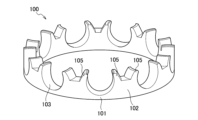
- FIG. 13 is a perspective view of a cage 100 according to a conventional example.
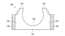
- FIG. 14 is a diagram of a part of a conventional cage 100 viewed from the inside in the radial direction.
- FIG. 15 is a diagram of a part of a conventional cage 100 viewed from the top side.
- the cage 100 includes an annular main part 101, a plurality of pillar parts 102 that protrude in the axial direction from the main part 101 at predetermined intervals in the circumferential direction, and adjacent pillar parts. Formed between 102, A spherical pocket 103 capable of holding the ball 6 is provided.
- the column portion 102 has a pair of claw portions 105, 105 whose tips are spaced apart from each other. Two adjacent claws 105, 105 forming the pocket 103 hold the balls 6, thereby preventing the retainer 100 from falling off in the axial direction from between the outer ring 5 and the inner ring 3. Further, the columnar portion 102 has a cutout 109 formed on the bottom surface side.
- the cage described in Patent Document 1 has an annular base and an axial part extending in the axial direction from the base.
- the outer diameter of the axial portion is smaller than the outer diameter of the base.
- a hole is formed in the base portion, communicating with the recessed region of the axial portion and penetrating in the axial direction. This reduces the amount of material, keeps the mass low, and suppresses radial deformation induced during high-speed rotation.
- the present invention has been made in view of the above circumstances, and aims to provide a crown-shaped cage for ball bearings and a ball bearing that can suppress deformation of the cage, reduce stress, and have good formability. purpose.
- An annular main part a plurality of pillar portions that protrude in the axial direction from the main portion at predetermined intervals in the circumferential direction; a pocket formed between the adjacent column parts and having a spherical concave surface capable of holding a ball;
- a crown-type cage for ball bearings comprising: The pillar portion has a pair of claw portions whose tips are spaced apart from each other, and a connection portion that connects the pair of claw portions, An entrance portion having a width shorter than the diameter of the ball and for inserting the ball is provided between the tips of the two adjacent claw portions constituting the pocket, A crown-type retainer for a ball bearing, wherein a distance from an outer circumferential surface of the pocket to a center of the crown-type retainer for a ball bearing is larger than a distance from an outer circumferential surface of the column part to the center.
- a convex portion protruding in the axial direction is provided on the bottom surface of the main portion, The crown-shaped retainer for a ball bearing according to (1), wherein the convex portion at least partially overlaps the pocket in the circumferential direction and the radial direction.
- crown-shaped retainer for ball bearings and the ball bearing of the present invention deformation of the retainer can be suppressed, stress can be reduced, and moldability is also good.
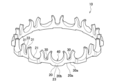
- FIG. 1 is a perspective view of a cage according to a first embodiment.
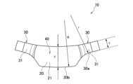
- FIG. 2 is a diagram of a portion of the cage according to the first embodiment viewed from the top side.
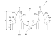
- FIG. 3 is a diagram of a portion of the cage according to the first embodiment viewed from the outside in the radial direction.
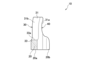
- FIG. 4 is a diagram of a part of the cage according to the first embodiment viewed from the circumferential direction.
- FIG. 5 is a perspective view of the cage according to the second embodiment.
- FIG. 6 is a view of a part of the cage according to the second embodiment, viewed from the top side.
- FIG. 7 is a diagram of a part of the cage according to the second embodiment viewed from the outside in the radial direction.
- FIG. 1 is a perspective view of a cage according to a first embodiment.
- FIG. 2 is a diagram of a portion of the cage according to the first embodiment viewed from the top side.
- FIG. 3 is a diagram of a portion of
- FIG. 8 is a diagram of a part of the cage according to the second embodiment viewed from the circumferential direction.
- FIGS. 9(a) to 9(c) are diagrams showing the maximum principal stress distribution generated in the cage due to centrifugal force.
- FIG. 10 is a diagram for explaining a model for analysis.
- FIGS. 11(a) and 11(b) are diagrams showing the strain distribution when the strain reaches the maximum in the cages of the first and second embodiments.
- FIG. 12 is a sectional view of a conventional ball bearing.
- FIG. 13 is a perspective view of a cage according to a conventional example.
- FIG. 14 is a diagram of a part of a conventional retainer viewed from the inside in the radial direction.
- FIG. 15 is a diagram of a part of a conventional cage viewed from the top side.
- FIG. 1 is a perspective view of a cage 10 according to the first embodiment.
- FIG. 2 is a diagram of a part of the cage 10 according to the first embodiment viewed from the top side.
- FIG. 3 is a diagram of a part of the cage 10 according to the first embodiment viewed from the outside in the radial direction.
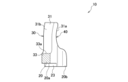
- FIG. 4 is a diagram of a part of the cage 10 according to the first embodiment viewed from the circumferential direction.
- a crown-shaped cage for ball bearings hereinafter also referred to as a "crown-shaped cage” or simply "cage” 10 of the present embodiment is shown in FIGS. 13 to 15. Similar to the conventional cage 100, it can be applied to the ball bearing 1 shown in FIG. 12.
- the crown-shaped retainer 10 is made of, for example, a resin material such as nylon 46 (polyamide 46, PA46), nylon 66 (polyamide 66, PA66), polyamide 9T (PA9T), polyamide 10T (PA10T), L-PPS, PEEK, etc. Or made of other resin materials. Further, in order to improve the strength of the cage 10, a resin composition may be used in which several tens of percent (for example, 10 to 50 wt%) of fibrous reinforcing material (carbon fiber, glass fiber, aramid fiber, etc.) is added. Examples of methods for manufacturing the cage 10 include injection molding using a mold and manufacturing using a 3D printer.
- the crown-shaped retainer 10 includes a substantially annular main portion 20, a plurality of pillar portions 30 protruding from the main portion 20 in the axial direction at predetermined intervals in the circumferential direction, and formed between adjacent pillar portions 30, 30. and a spherical pocket 40 that can hold the ball 6 (see FIG. 12).
- a plurality of spherical concave surfaces 21 are formed on the upper surface of the main portion 20 at predetermined intervals in the circumferential direction. This spherical concave surface 21 is formed over the entire width of the main portion 20 in the radial direction, and constitutes a pocket 40.
- the column portion 30 protrudes from the main portion 20 in the axial direction.
- the column part 30 has a pair of claw parts 31, 31 and a connecting part 33 that connects the pair of claw parts 31, 31.
- the tip ends of the pair of claws 31, 31 are spaced apart from each other in the circumferential direction. Furthermore, the space between the tips of the two adjacent claws 31, 31 constituting the pocket 40 has a width shorter than the diameter of the ball 6 (see FIG. 12), and is used for inserting the ball 6. An inlet portion 35 is provided.
- the claw portion 31 has a spherical first circumferential surface 31a that constitutes the pocket 40, and a second circumferential surface 31b opposite to the first circumferential surface 31a.
- the second circumferential surfaces 31b, 31b of the pair of claws 31, 31 are curved, respectively, and are smoothly connected at the upper surface 33a of the connecting portion 33.
- the upper surface 33a of this connecting portion 33 corresponds to a substantially U-shaped bottom formed by the upper surface 33a and a pair of circumferential second surfaces 31b, 31b.
- the upper surface 33a of the connecting portion 33 (the bottom of the pair of circumferential second surfaces 31b, 31b) is located slightly above the bottom of the pocket 40 (on one side in the axial direction).
- the bottoms of the pair of circumferential second surfaces 31b, 31b are located below (on the other side in the axial direction) than the axial center of the retainer 10, and are formed into approximately U-shaped recesses.
- the upper surface of the connecting portion is located considerably above the upper surface of the main portion 101, It is located above the axial center of the retainer 100 (on one side in the axial direction). Thereby, the weight of the column 30 is reduced, and the mass of the column 30 is suppressed.
- the axial width h1 from the top surface 33a of the connecting portion 33 to the bottom surface 20a of the main portion 20 is set to 1/2 or less of the axial width H of the cage 10 (h1 ⁇ H/2). Note that if the axial width h1 is made too small, the strength of the cage 10 may decrease, so the axial width h1 should be made larger than the axial width h2 of the main portion 20 at the bottom of the pocket 40. is preferable (h1>h2).
- the circumferential first surfaces 31a, 31a of the two adjacent claw portions 31, 31 and the spherical concave surface 21 of the main portion 20 constitute a pocket 40. These two circumferential first surfaces 31a, 31a and the spherical concave surface 21 are smoothly connected to each other and constitute the spherical concave surface of the pocket 40.
- the radius of curvature of the spherical concave surface of the pocket 40 is set larger than the radius of curvature of the rolling surface of the ball 6 (see FIG. 12).
- the outer diameter R of the pocket 40 (the outer diameter at the circumferential position where the pocket 40 is formed in the main portion 20) is set larger than the outer diameter r of the column portion 30 and the claw portion 31. Ru. That is, the distance R from the outer circumferential surface of the pocket 40 (the outer circumferential surface 20b at the circumferential position where the pocket 40 is formed in the main portion 20) to the center of the cage 10 is the distance R from the outer circumferential surface 30a of the column part 30 to the center of the cage 10. (R>r).
- the radial width t of the columnar portion 30 is set to be less than or equal to the radial width of the bottom of the pocket 40 (the radial width of the circumferential position of the main portion 20 where the bottom of the pocket 40 is formed) (t ⁇ T).
- the distance R from the outer peripheral surface of the pocket 40 to the center of the cage 10 is the distance R from the outer peripheral surface 30a of the column part 30 to the center of the cage 10. It is set larger than the distance r (R>r). Therefore, the retainer 10 has a structure in which the portion other than the pocket 40, that is, the radially outer side of the column portion 30 is removed, and the weight is reduced. In addition, unlike conventional cages, the cage does not have a hollow structure to reduce weight, so moldability is also good.
- the cage 10 can be molded without deteriorating the fluidity of the resin during molding, and the weight can be reduced. Therefore, deformation and stress caused by centrifugal force during high-speed rotation can be suppressed. Therefore, the cage 10 can be prevented from coming into contact with the outer ring 5, the shield plate 7, etc., and wear, vibration, heat generation, and damage of the cage 10 can be suppressed.
- FIG. 5 is a perspective view of the cage 10 according to the second embodiment.
- FIG. 6 is a view of a part of the cage 10 according to the second embodiment, viewed from the top side.
- FIG. 7 is a diagram of a part of the cage 10 according to the second embodiment viewed from the outside in the radial direction.
- FIG. 8 is a diagram of a part of the cage 10 according to the second embodiment viewed from the circumferential direction.
- the cage 10 of the present embodiment differs from the cage 10 of the second embodiment (see FIGS. 1 to 4) in that a convex portion 23 is provided on the bottom surface 20a of the main portion 20 and protrudes toward the other side in the axial direction. . Since the other configurations are the same as those in the first embodiment, the description thereof will be omitted or simplified by giving the same reference numerals.
- the convex portion 23 is located between the circumferentially adjacent pillar portions 30, 30 on the other axial side (downward) from the bottom surface 20a of the main portion 20, in the opposite direction to the direction in which the claw portion 31 extends in the vertical direction in FIG. .) to protrude. That is, the bottom surface 20a of the main portion 20 has a plurality of convex portions 23 formed below the plurality of pockets 40 at predetermined intervals in the circumferential direction.
- the convex portion 23 overlaps the pocket 40 in the circumferential direction and the radial direction.
- the circumferential range and radial range in which the convex portion 23 is provided are substantially the same as the circumferential range and radial range in which the spherical concave surface 21 of the main portion 20 constituting the pocket 40 is provided.
- the structure will be substantially the same as that of the first embodiment, and the effect of reducing the strain generated in the claw portion 31 during assembly, which will be described later, will not be very effective. . Furthermore, if the circumferential range in which the convex portion 23 is provided is too narrow, the shortest distance between the roots of both ends of the convex portion 23 in the circumferential direction and the spherical concave surface 21 becomes small, and the stress generated in the pocket 40 due to centrifugal force is reduced. , it will be higher than the bottom of the pocket.
- the radial range in which the convex portion 23 is provided is substantially the same as the radial range in which the spherical concave surface 21 is provided, it is possible to eliminate the step and suppress the generation of high stress at the step. Therefore, it is preferable that the circumferential range and radial range in which the convex portion 23 is provided are substantially the same as the circumferential direction range and radial direction range in which the spherical concave surface 21 of the main portion 20 constituting the pocket 40 is provided.
- the radial width and circumferential width of the convex portion 23 in this embodiment are approximately the same as the radial width (radial width of the main portion 20) and circumferential width of the pocket 40.
- the effect of suppressing stress and deformation caused by centrifugal force is not much different from that of the first embodiment, but the cage 10 is connected to the inner ring 3, the outer ring 5, and the balls. It is effective when incorporated into the ball bearing 1 consisting of 6. That is, the strain generated in the claw portions 31 of the retainer 10 is reduced.
- Example 1 In order to confirm the effects of the first and second embodiments, analysis was performed using the finite element method. In this analysis, when the cages 10 of the first and second embodiments and the cage 100 of the conventional example (see FIGS. 13 to 15) are rotated, the maximum main force generated in the cages 10 and 100 due to centrifugal force is The stress distribution was calculated.
- the radial width of the cage 100 in the conventional example was 3.3 mm.
- the radial width T of the bottom of the pocket 40 was 3.3 mm.
- the axial width of the convex portion 23 was 0.5 mm.
- the axial widths of all cages 10 and 100 were the same.
- FIGS. 9A to 9C are diagrams showing the maximum principal stress distribution generated in the cages 10 and 100 due to centrifugal force.
- 9(a) corresponds to a cage 100 of a conventional example
- FIG. 9(b) corresponds to a cage 10 of a first embodiment
- FIG. 9(c) corresponds to a cage 10 of a second embodiment.
- the stress value was taken as a relative value. It can be seen that the largest stress is generated in the cage 100 of the conventional example. On the other hand, it can be seen that in the cages 100 of the first and second embodiments, the stress generated at the pocket bottom is suppressed to less than half that of the cage 100 of the conventional example.
- each pocket is connected by the main part, so when centrifugal force acts on the main part, the claws tend to fall radially outward due to the centrifugal force that acts on the claws. .
- the cages 10 of the first and second embodiments have smaller radial widths of the claws 31, so the mass is smaller, and the centrifugal force acting on the claws 31 is correspondingly smaller. Become. Therefore, it is thought that the claw portion 31 is less likely to fall down and the stress generated at the bottom of the pocket is reduced.
- Example 2 The cage 10 of the first embodiment without the convex portion 23 on the bottom surface 20a of the main portion 20 and the cage 10 of the second embodiment with the convex portion 23 on the bottom surface 20a of the main portion 20 are combined into an inner ring 3, an outer ring 5, The strain generated in the claw portion 31 of the retainer 10 when assembled into the ball bearing 1 consisting of the balls 6 was analyzed and calculated using the finite element method.
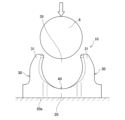
- FIG. 10 is a diagram for explaining a model for analysis. As shown in FIG. 10, in the model for analysis, a part of the cage 10 was taken out and balls 6 were pushed in little by little.
- FIGS. 11(a) and 11(b) are diagrams showing the strain distribution when the strain reaches the maximum in the cage 100 of the first and second embodiments.
- the maximum strain occurring in the claw portion 31 of the cage 10 in the first embodiment shown in FIG. 11(a) is 1.9%
- the maximum strain occurring in the claw portion 31 of the cage 10 in FIG. 11(b) is 1.9%.
- the value was 1.2%, and the strain was significantly reduced, which indicates that providing the convex portion 23 has the effect of reducing strain.
- the cage 10 of the second embodiment shown in FIG. 11(b) has a larger distance from the tip of the claw part 31 to the fulcrum P than the cage 10 of the first embodiment shown in FIG. 11(a). Since the distance is longer, the strain generation region D is expanded, and the strain is further reduced than in Example 1.
- the cage 10 of the second embodiment is applied to a cage using a resin material such as polyamide 9T (PA9T) or polyamide 10T (PA10T), which has lower elongation than nylon 46 or nylon 66, the strain can be reduced. This is suitable.
Landscapes
- Engineering & Computer Science (AREA)
- General Engineering & Computer Science (AREA)
- Mechanical Engineering (AREA)
- Rolling Contact Bearings (AREA)
Abstract
Description
玉6を保持可能な球面形状のポケット103と、を備える。
(1) 円環状の主部と、
前記主部から周方向に所定の間隔で軸方向に突出する複数の柱部と、
隣り合う前記柱部の間に形成され、玉を保持可能な球面形状の球状凹面を有するポケットと、
を備える、玉軸受用冠型保持器であって、
前記柱部は、先端部が互いに間隔をあけて配置される一対の爪部と、前記一対の爪部を接続する接続部と、を有し、
前記ポケットを構成する隣り合う二つの前記爪部の先端部同士の間には、前記玉の直径より短い幅を有し、かつ、前記玉を挿入するための、入口部が設けられ、
前記ポケットの外周面から前記玉軸受用冠型保持器の中心までの距離は、前記柱部の外周面から前記中心までの距離よりも大きいことを特徴とする玉軸受用冠型保持器。
(2) 前記主部の底面には、軸方向に突出する凸部が設けられ、
前記凸部は、少なくとも一部が、周方向及び径方向において前記ポケットと重なる
(1)に記載の玉軸受用冠型保持器。
(3) 外輪と、
内輪と、
前記外輪と、前記内輪と、の間に配置された複数の前記玉と、
(1)又は(2)に記載の玉軸受用冠型保持器と、
を備える、玉軸受。
図1は、第一実施形態に係る保持器10の斜視図である。図2は、第一実施形態に係る保持器10の一部を上面側から見た図である。図3は、第一実施形態に係る保持器10の一部を径方向外側から見た図である。図4は、第一実施形態に係る保持器10の一部を周方向から見た図である。図1~図4に示すように、本実施形態の玉軸受用冠型保持器(以下、「冠型保持器」、又は単に「保持器」とも称す)10は、図13~図15に示す従来の保持器100と同様に、図12に示す玉軸受1に適用され得る。
次に、本発明の第二実施形態に係る玉軸受用冠型保持器について、図面を用いて説明する。
第一及び第二実施形態の効果を確かめるために、有限要素法による解析を実施した。本解析では、第一及び第二実施形態の保持器10並びに従来例(図13~図15参照)の保持器100を回転させた際に、遠心力により保持器10,100に発生する最大主応力分布を算出した。
主部20の底面20aに凸部23のない第一実施形態の保持器10と、主部20の底面20aに凸部23のある第二実施形態の保持器10を、内輪3、外輪5、玉6からなる玉軸受1に組み込む際に保持器10の爪部31に発生するひずみを有限要素法による解析を実施し、算出した。図10は、解析用のモデルを説明するための図である。図10に示すように、解析用のモデルにおいては、保持器10の一部分を取り出し、玉6を少しずつ押し込んでいった。
2 内輪軌道
3 内輪
4 外輪軌道
5 外輪
6 玉
7 シールド板
10 玉軸受用冠型保持器
20 主部
20a 底面
20b 外周面
21 球状凹面
23 凸部
30 柱部
30a 外周面
31 爪部
31a 周方向第一面
31b 周方向第二面
33 接続部
33a 上面
35 入口部
40 ポケット
H,h1,h2 軸方向幅
Claims (3)
- 円環状の主部と、
前記主部から周方向に所定の間隔で軸方向に突出する複数の柱部と、
隣り合う前記柱部の間に形成され、玉を保持可能な球面形状の球状凹面を有するポケットと、
を備える、玉軸受用冠型保持器であって、
前記柱部は、先端部が互いに間隔をあけて配置される一対の爪部と、前記一対の爪部を接続する接続部と、を有し、
前記ポケットを構成する隣り合う二つの前記爪部の先端部同士の間には、前記玉の直径より短い幅を有し、かつ、前記玉を挿入するための、入口部が設けられ、
前記ポケットの外周面から前記玉軸受用冠型保持器の中心までの距離は、前記柱部の外周面から前記中心までの距離よりも大きいことを特徴とする玉軸受用冠型保持器。 - 前記主部の底面には、軸方向に突出する凸部が設けられ、
前記凸部は、少なくとも一部が、周方向及び径方向において前記ポケットと重なる
請求項1に記載の玉軸受用冠型保持器。 - 外輪と、
内輪と、
前記外輪と、前記内輪と、の間に配置された複数の前記玉と、
請求項1又は2に記載の玉軸受用冠型保持器と、
を備える、玉軸受。
Priority Applications (4)
| Application Number | Priority Date | Filing Date | Title |
|---|---|---|---|
| CN202380034307.0A CN119032226A (zh) | 2022-04-15 | 2023-03-06 | 滚珠轴承用冠型保持架及滚珠轴承 |
| JP2024514845A JPWO2023199646A1 (ja) | 2022-04-15 | 2023-03-06 | |
| US18/856,519 US20250271032A1 (en) | 2022-04-15 | 2023-03-06 | Crown-type retainer for ball bearing, and ball bearing |
| DE112023001931.2T DE112023001931T5 (de) | 2022-04-15 | 2023-03-06 | Kronenförmiger Halter für ein Kugellager und Kugellager |
Applications Claiming Priority (2)
| Application Number | Priority Date | Filing Date | Title |
|---|---|---|---|
| JP2022-067904 | 2022-04-15 | ||
| JP2022067904 | 2022-04-15 |
Publications (1)
| Publication Number | Publication Date |
|---|---|
| WO2023199646A1 true WO2023199646A1 (ja) | 2023-10-19 |
Family
ID=88329355
Family Applications (1)
| Application Number | Title | Priority Date | Filing Date |
|---|---|---|---|
| PCT/JP2023/008431 Ceased WO2023199646A1 (ja) | 2022-04-15 | 2023-03-06 | 玉軸受用冠型保持器、及び玉軸受 |
Country Status (5)
| Country | Link |
|---|---|
| US (1) | US20250271032A1 (ja) |
| JP (1) | JPWO2023199646A1 (ja) |
| CN (1) | CN119032226A (ja) |
| DE (1) | DE112023001931T5 (ja) |
| WO (1) | WO2023199646A1 (ja) |
Cited By (1)
| Publication number | Priority date | Publication date | Assignee | Title |
|---|---|---|---|---|
| WO2026070602A1 (ja) * | 2024-09-24 | 2026-04-02 | Ntn株式会社 | 玉軸受 |
Citations (3)
| Publication number | Priority date | Publication date | Assignee | Title |
|---|---|---|---|---|
| JP2007327514A (ja) * | 2006-06-06 | 2007-12-20 | Nsk Ltd | 玉軸受 |
| JP2009536998A (ja) * | 2006-05-12 | 2009-10-22 | アクチボラゲット エス ケイ エフ | ボール軸受のための保持器及びころがり軸受組立体 |
| CN111649068A (zh) * | 2020-07-20 | 2020-09-11 | 马纯 | 一种高速轴承保持架 |
Family Cites Families (1)
| Publication number | Priority date | Publication date | Assignee | Title |
|---|---|---|---|---|
| JP7645062B2 (ja) | 2020-10-21 | 2025-03-13 | Nok株式会社 | 摺動構造 |
-
2023
- 2023-03-06 DE DE112023001931.2T patent/DE112023001931T5/de active Pending
- 2023-03-06 JP JP2024514845A patent/JPWO2023199646A1/ja active Pending
- 2023-03-06 US US18/856,519 patent/US20250271032A1/en active Pending
- 2023-03-06 CN CN202380034307.0A patent/CN119032226A/zh active Pending
- 2023-03-06 WO PCT/JP2023/008431 patent/WO2023199646A1/ja not_active Ceased
Patent Citations (3)
| Publication number | Priority date | Publication date | Assignee | Title |
|---|---|---|---|---|
| JP2009536998A (ja) * | 2006-05-12 | 2009-10-22 | アクチボラゲット エス ケイ エフ | ボール軸受のための保持器及びころがり軸受組立体 |
| JP2007327514A (ja) * | 2006-06-06 | 2007-12-20 | Nsk Ltd | 玉軸受 |
| CN111649068A (zh) * | 2020-07-20 | 2020-09-11 | 马纯 | 一种高速轴承保持架 |
Cited By (1)
| Publication number | Priority date | Publication date | Assignee | Title |
|---|---|---|---|---|
| WO2026070602A1 (ja) * | 2024-09-24 | 2026-04-02 | Ntn株式会社 | 玉軸受 |
Also Published As
| Publication number | Publication date |
|---|---|
| DE112023001931T5 (de) | 2025-02-27 |
| JPWO2023199646A1 (ja) | 2023-10-19 |
| US20250271032A1 (en) | 2025-08-28 |
| CN119032226A (zh) | 2024-11-26 |
Similar Documents
| Publication | Publication Date | Title |
|---|---|---|
| JP7420274B2 (ja) | 玉軸受用冠型保持器、及び玉軸受 | |
| JP5436204B2 (ja) | ボール軸受のための保持器及びころがり軸受組立体 | |
| CN103688069B (zh) | 球轴承用的合成树脂制保持器以及球轴承 | |
| US8292512B2 (en) | Ball bearing and supporting construction | |
| KR102769415B1 (ko) | 볼 베어링용 관형 유지기 및 볼 베어링 | |
| JP2008286319A (ja) | クリーナモータ軸受用合成樹脂製冠型保持器、クリーナモータ用転がり軸受 | |
| JP2021167649A (ja) | 転がり軸受 | |
| US10907686B2 (en) | Flexible cage for rolling bearing | |
| US20250271032A1 (en) | Crown-type retainer for ball bearing, and ball bearing | |
| US20250264132A1 (en) | Crown-type retainer for ball bearing, and ball bearing | |
| JP5272737B2 (ja) | 冠型保持器及び玉軸受 | |
| JP5029733B2 (ja) | 玉軸受 | |
| JP2009008170A (ja) | 樹脂製保持器及び該保持器を使用した玉軸受 | |
| JP7069577B2 (ja) | 深溝玉軸受用冠型樹脂保持器 | |
| JP2008128296A (ja) | ラジアル玉軸受用合成樹脂製冠型保持器及びラジアル玉軸受 | |
| JP2009057998A (ja) | 玉軸受用冠型保持器及び玉軸受 | |
| JP2007032821A (ja) | 転がり軸受用樹脂製保持器及び転がり軸受 | |
| JP2007327516A (ja) | 深溝玉軸受 | |
| KR101992647B1 (ko) | 볼 베어링용 케이지 | |
| JP2025051174A (ja) | 玉軸受用冠型保持器、及び玉軸受 | |
| JP2007056930A (ja) | 転がり軸受用樹脂製保持器及び転がり軸受 | |
| JP2006200615A (ja) | 転がり軸受用冠型保持器 | |
| JP2024084988A (ja) | 冠型保持器、及び玉軸受 | |
| JP7452710B2 (ja) | 玉軸受用冠型保持器、及び玉軸受 | |
| JP5131068B2 (ja) | 冠型保持器 |
Legal Events
| Date | Code | Title | Description |
|---|---|---|---|
| 121 | Ep: the epo has been informed by wipo that ep was designated in this application |
Ref document number: 23788068 Country of ref document: EP Kind code of ref document: A1 |
|
| WWE | Wipo information: entry into national phase |
Ref document number: 2024514845 Country of ref document: JP |
|
| WWE | Wipo information: entry into national phase |
Ref document number: 18856519 Country of ref document: US |
|
| WWE | Wipo information: entry into national phase |
Ref document number: 202380034307.0 Country of ref document: CN |
|
| WWE | Wipo information: entry into national phase |
Ref document number: 112023001931 Country of ref document: DE |
|
| WWP | Wipo information: published in national office |
Ref document number: 112023001931 Country of ref document: DE |
|
| 122 | Ep: pct application non-entry in european phase |
Ref document number: 23788068 Country of ref document: EP Kind code of ref document: A1 |
|
| WWP | Wipo information: published in national office |
Ref document number: 18856519 Country of ref document: US |