WO2023199489A1 - 加振器の固定装置及び加振システム - Google Patents
加振器の固定装置及び加振システム Download PDFInfo
- Publication number
- WO2023199489A1 WO2023199489A1 PCT/JP2022/017865 JP2022017865W WO2023199489A1 WO 2023199489 A1 WO2023199489 A1 WO 2023199489A1 JP 2022017865 W JP2022017865 W JP 2022017865W WO 2023199489 A1 WO2023199489 A1 WO 2023199489A1
- Authority
- WO
- WIPO (PCT)
- Prior art keywords
- shaft member
- attached
- vibrator
- vibration
- fixing device
- Prior art date
- Legal status (The legal status is an assumption and is not a legal conclusion. Google has not performed a legal analysis and makes no representation as to the accuracy of the status listed.)
- Ceased
Links
Images






Classifications
-
- G—PHYSICS
- G01—MEASURING; TESTING
- G01M—TESTING STATIC OR DYNAMIC BALANCE OF MACHINES OR STRUCTURES; TESTING OF STRUCTURES OR APPARATUS, NOT OTHERWISE PROVIDED FOR
- G01M7/00—Vibration-testing of structures; Shock-testing of structures
- G01M7/02—Vibration-testing by means of a shake table
-
- G—PHYSICS
- G01—MEASURING; TESTING
- G01M—TESTING STATIC OR DYNAMIC BALANCE OF MACHINES OR STRUCTURES; TESTING OF STRUCTURES OR APPARATUS, NOT OTHERWISE PROVIDED FOR
- G01M7/00—Vibration-testing of structures; Shock-testing of structures
- G01M7/02—Vibration-testing by means of a shake table
- G01M7/027—Specimen mounting arrangements, e.g. table head adapters
Definitions
- the present invention relates to a vibration exciter fixing device and an excitation system.
- Non-Patent Document 1 When constructing a structure, it is known to measure the natural frequency of the structure through modal experiments in order to prevent resonance from occurring in the structure (see Non-Patent Document 1). The simplest and most common method of modal experimentation is performed using an impulse hammer and an accelerometer.
- Impulse hammers vibrate structures using human power, so when a large structure such as a bridge is vibrated by an impulse hammer, the excitation force is significantly attenuated, making it impossible to measure the resonant frequency with the desired accuracy. There is. In contrast, general vibrators used in modal experiments can excite at a magnitude sufficient to measure the resonant frequency of a large structure with desired accuracy.
- Non-Patent Document 2 describes a vibration exciter that is installed on the side of an automobile by being attached to a fixing device to vibrate the side surface of the automobile.
- Non-Patent Document 3 describes a vibrator that is installed on the ground and vibrates the wings of a UAV (Unmanned Aerial Vehicle) from below to above.
- UAV Unmanned Aerial Vehicle
- Non-Patent Document 2 can vibrate the object from the side by moving the vibrator in the vertical direction, it cannot vibrate the object from above or below. Can not. Further, although the vibrator of Non-Patent Document 3 can vibrate the object from below, it cannot vibrate the object from above or from the side.
- the attachment pipes are provided at various positions and on various sides (upper side, lower side, left side, right side, etc.) of the large structure.
- the attached pipe may be provided on the underside of a bridge using a bridge girder of a bridge, which is a large structure. Therefore, in a vibration characteristic test, it is desirable that the vibrator be installed at various positions so as to be able to vibrate the structure in both the vertical and horizontal directions.
- a fixing device includes a base, a first shaft member provided on the base and extending in a first direction, and a first shaft member provided on the base. attached to, extends in a second direction perpendicular to the first direction, and is movable in the first direction and the second direction relative to the first shaft member. and a second shaft member to which a vibrator is attached.
- an excitation system including a fixing device and a vibrator attached to the fixing device, wherein the fixing device is attached to a base. a first shaft member provided on the base and extending in a first direction; and a second shaft member attached to the first shaft member and perpendicular to the first direction. a second shaft member extending in the direction and movable in the first direction and the second direction relative to the first shaft member, the vibrator comprising: It is attached to the second shaft member.
- a fixing device and an excitation system in which a vibrator can be installed so that a structure can be vibrated both vertically and horizontally at various positions. It is in.
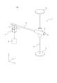
- FIG. 1 is a perspective view showing an example of a vibration system according to a first embodiment.
- FIG. 2 is a perspective view of the vibration system in a state where the second shaft member shown in FIG. 1 is moved in the horizontal direction.
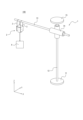
- FIG. 2 is a perspective view of the vibration system in a state where the second shaft member shown in FIG. 1 is moved in the vertical direction.
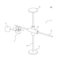
- FIG. 2 is a perspective view of the vibration system in a state where the second shaft member shown in FIG. 1 has moved in the horizontal and vertical directions.
- FIG. 2 is a diagram showing details of the vibrator shown in FIG. 1;
- FIG. 2 is a perspective view showing a mode in which the vibrator shown in FIG. 1 is oriented in different directions.
- FIG. 2 is a perspective view showing an example in which the vibrator shown in FIG.
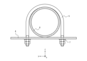
- FIG. 1 is attached to a fixing device in a different manner. It is a perspective view of the attachment pipe which is an example of the object which a vibrator excites.
- FIG. 8A is a sectional view taken along line AA in FIG. 8A. It is a perspective view showing an example of an excitation system concerning a 2nd embodiment.
- FIG. 10 is a perspective view showing a state in which the vibration system shown in FIG. 9 is installed to vibrate an additional pipe.
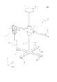
- FIG. 1 is a schematic diagram of an excitation system 100 according to this embodiment.
- the vibration system 100 includes a fixing device 1, a vibration exciter 2, and a mounting member 3.
- the fixing device 1 includes a base 11 , a first shaft member 12 , a second shaft member 13 , and a shaft fixing part 14 .
- the fixing device 1 may further include a top plate 15.
- the base 11 is a stand on which the first shaft member 12 is provided.
- the base 11 may have a flat surface.
- the base 11 is a flat member having two circular surfaces facing oppositely to each other.
- the shape of the surface of the base 11 may be any shape such as a polygon or an ellipse.
- the base 11 is stably installed by being arranged so that the flat surface of the base 11 is in contact with the ground.
- the first shaft member 12 is a member provided on the base 11 and extending in the first direction.
- the first shaft member 12 is located on the opposite side to the one plane that the base 11 has (the plane that contacts the ground when the fixing device 1 is used). and extends in a direction perpendicular to the plane.
- the first direction is the vertical direction (Z-axis direction in FIG. 1).
- the first shaft member 12 may be configured integrally with the base 11 or may be configured separately from the base 11 and attached to the base 11.
- the second shaft member 13 is attached to the first shaft member 12 and extends in a second direction perpendicular to the first direction. Therefore, as described above, when the first direction is the vertical direction (Z-axis direction in FIG. 1), the second direction is the horizontal direction (X-axis direction in FIG. 1). Further, the vibrator 2 is attached to the second shaft member 13.
- the second shaft member 13 is movable in the second direction (X-axis direction in FIG. 1) relative to the first shaft member 12.
- the second shaft member 13 may be arranged so as not to contact the first shaft member 12, and at any position along the first shaft member 12, the shaft fixing portion 14 may cause the second shaft member 13 to 12.
- the second shaft member 13 may be fixed to the first shaft member 12 by the shaft fixing portion 14 so that the length from the intersection to the end is a desired length.
- the intersection portion is a portion of the second shaft member 13 that is attached to the first shaft member 12. For example, when the second shaft member 13 moves from the state shown in FIG. 1 in the second direction (the negative direction of the X-axis in FIG. 1), as shown in FIG.
- the portion of the second shaft member 13 located on one side of the shaft member 12 in the example of FIG. 2, the negative side of the X-axis
- the second shaft member 13 is movable in the first direction (in the example of FIG. 3, the Z-axis direction) relative to the first shaft member 12.
- the second shaft member 13 may be attached to the first shaft member 12 such that the length from the intersection to the end of the first shaft member 12 is a desired length.
- the portion of the first shaft member 12 located on one side of the shaft member 13 is located on the other side of the second shaft member 13 (in the example of FIG. (direction side).
- the second shaft member 13 is movable in the first direction and the second direction relative to the first shaft member 12.
- the portion of the second shaft member 13 located on one side of the first shaft member 12 (in the example of FIG. 4, the negative side of the X axis) is located on the other side of the first shaft member 12 (in the example of FIG. 4). It is longer than the part located on the positive side of the X-axis).
- a portion of the first shaft member 12 located on one side of the second shaft member 13 is located on the other side of the second shaft member 13 of the first shaft member 12. It is longer than the portion located on the side (in the example of FIG. 4, the positive direction side of the Z axis).
- the shaft fixing part 14 is a member that fixes the second shaft member 13 to the first shaft member 12.
- the shaft fixing part 14 can have any mechanism for fixing the second shaft member 13 to the first shaft member 12, and can fix the second shaft member 13 to the first shaft member 12 by any method. It can be fixed to
- the top plate 15 is provided at the end of the first shaft member 12 on the opposite side to the side where the base 11 is provided.
- the top plate 15 is a flat member having two circular surfaces facing oppositely to each other, and one surface of the top plate 15 is connected to the base 11 of the first shaft member 12. It is provided at the end opposite to the side where it is provided.
- the shape of the surface of the top plate 15 may be any shape such as a polygon or an ellipse.
- the top plate 15 does not need to have a surface and may have any shape.
- Each member of the fixing device 1 has such rigidity that the degree of deformation due to reaction force when the vibrator 2 attached to the fixing device 1 excites the object A is equal to or less than a predetermined value. made of material.
- the predetermined value is a degree of deformation that can be ignored in a vibration characteristic test of the object A.
- the exciter 2 includes an exciter main body 21, a first covering surface 22, and two second covering surfaces 23 (second covering surfaces 231 and 232). including.
- the vibrator 2 is attached to the second shaft member 13 of the fixing device 1 .
- the vibrator 2 is attached to the second shaft member 13 by suspending the attachment member 3 from the second shaft member 13 .
- a specific manner in which the attachment member 3 attaches the vibrator 2 to the second shaft member 13 will be described in detail later.
- the vibrator body 21 vibrates the object A.
- the vibrator main body 21 includes a drive section 21a and a stinger 21b.
- the drive unit 21a generates vibrations.
- the stinger 21b is a needle-shaped member held on the drive portion 21a by a screw or the like.
- the stinger 21b is driven by the drive unit 21a and vibrates in the excitation direction, thereby exciting the object A that is in contact with the tip of the stinger 21b.
- the direction of vibration is the direction from the part of the stinger 21b attached to the drive part 21a toward the tip.
- the first covering surface 22 is a planar member that covers the surface (bottom surface) of the vibration exciter main body 21 on the opposite side to the vibration direction.
- the first covered surface 22 is a planar member disposed on the side of the vibrator main body 21 to which the stinger 21b is not attached and is perpendicular to the vibration direction.
- the first covering surface 22 may have a hole passing through the first covering surface 22.
- the first covering surface 22 has four holes 22a, 22b, 22c, and 22d.
- the planar shape of the first covering surface 22 is a rectangle, and each of the four corners of the rectangle has four holes 22a, 22b, 22c, and 22d.
- the second covering surfaces 231 and 232 are planar members that cover the surfaces (side surfaces) of the vibration exciter main body 21 that are parallel to the vibration direction.
- the second covering surfaces 231 and 232 are opposed to each other.
- Each of the second covering surfaces 231 and 232 may have a hole passing through each of the second covering surfaces 231 and 232, respectively.
- the second covering surface 231 has two holes 231a and 231b
- the second covering surface 232 has two holes 232a and 232b.
- the planar shape of the second covering surface 231 may be rectangular.
- the second covering surface 231 has two holes 231a and 231b at each of two corners adjacent to each other in the excitation direction
- the second covering surface 232 has two holes 231a and 231b at two corners adjacent to each other in the excitation direction. It has two holes 232a and 232b at each corner opposite to each other.
- the vibrator 2 may further include a rotating shaft member 24.
- the rotating shaft member 24 is configured such that the exciter main body 21 is rotatable about an axis ( ⁇ axis) extending in the normal direction of the two mutually parallel second covering surfaces 231 and 232. It is a member that has been
- the rotating shaft member 24 may be a member that is attached to the vibrator body 21, slides on the second covering surfaces 231 and 232, and rotates together with the vibrator body 21 around the ⁇ axis.
- the rotating shaft member 24 is attached to the side surface on the second covered surfaces 231 and 232 side, and the vibration exciter main body 21 rotates around the ⁇ axis by sliding around the rotating shaft member 24. It may be a provided member.
- the first covered surface 22 is configured to cover the vibration exciter body 21 in a predetermined state (the state before the vibration exciter body 21 rotates). It is a planar member that covers the surface (bottom surface) on the opposite side to the vibration direction.
- the first covering surface 22 is a surface (side surface) of the exciter body 21 that is parallel to the excitation direction.
- the second covering surfaces 231 and 232 cover the surfaces that are not covered.
- the first covered surface 22 may have a hole, and the second covered surfaces 231 and 232 may not have a hole. Furthermore, in the configuration in which the vibrator 2 includes the rotating shaft member 24, the first covering surface 22 may have no holes, and the second covering surfaces 231 and 232 may have holes.
- the attachment member 3 is a member for attaching the vibrator 2 to the fixing device 1.
- the attachment member 3 may be a member attached to the vibrator 2 and suspended from the second shaft member 13 of the fixing device 1.
- the attachment member 3 can be a string-like elastic member.
- the attachment member 3 is attached to the first covering surface 22 via a hole penetrating the first covering surface 22 or via a hole penetrating the second covering surface 23. and is attached to the second covering surface 23.
- the attachment member 3 is attached to the first covering surface 22 through the hole that the first covering surface 22 has. .
- one mounting member 3 is fixed to the first covered surface 22 by passing through two holes (holes 22a and 22b in the example of FIG. 5) at both ends. , attached to the first covering surface 22.
- the other mounting member 3 is fixed to the first covered surface 22 by passing through two holes (holes 22c and 22d in the example of FIG. 5) at both ends, respectively. It is attached to the covered surface 22 of.
- the mounting member 3 whose end portion is fixed to the first covering surface 22 in this manner is suspended from the second shaft member 13 so that the stinger 21b of the vibrator 2 contacts the upper part of the object A. Ru.
- the vibrator 2 vibrates the object A from the side, as shown in FIG. It is attached to the two second covering surfaces 23 by passing through and fixing the holes (holes 231a and 232a in FIG. 5).
- both ends of the other mounting member 3 pass through the respective holes (holes 231b and holes 232b in FIG. 5) of the two second covering surfaces 23 and connect to the second covering surface 23.
- the second covering surfaces 231 and 232 are attached.
- the mounting member 3 whose ends are fixed to the second covered surfaces 231 and 232 in this way is attached to the second shaft member 13 so that the stinger 21b of the vibrator 2 comes into contact with the side of the object A. suspended in the.
- the mounting member 3 may be formed of an elastic material. Thereby, it is possible to suppress the frequency of the vibration applied to the object A from changing from the frequency of the vibration generated by the vibrator 2. Further, the end of the mounting member 3 does not pass through the hole described above, but connects to the first covering surface 22 or the second covering surface 231 and the like through an S-shaped hook passing through the hole. 232.
- the fixing device 1 may include a mounting member 3-1 instead of the mounting member 3.
- the attachment member 3-1 may be a rigid connection member that rigidly connects the vibrator 2 to the second shaft member 13.
- the rigid member may be a screw, a pin, or the like.
- the first covering surface 22 is attached to the second shaft member 13 by the mounting member 3-1, as shown in FIG. It is rigidly connected to the bottom.
- the first covered surface 22 is rigidly connected to the upper side of the second shaft member 13 by the attachment member 3-1.
- the first covered surface 22 is rigidly connected to the second shaft member 13 by the attachment member 3-1.
- the vibrator 2 may include the rotating shaft member 24, and in such a configuration, as shown in FIG. It may be attached to the first covering surface 22 and suspended from the second shaft member 13 via. In this case, the vibrator main body 21 is rotated by the rotating shaft member 24 so that the direction from the vibrator 2 toward the object A is the vibration direction.
- the vibrator 2 includes the rotating shaft member 24 as described above, as shown in FIG. It may be attached to one second covered surface 23.
- the vibrator main body 21 is rotated by the rotating shaft member 24 so that the direction from the vibrator 2 toward the object A is the vibration direction.
- the fixing device 1 includes the base 11, the first shaft member 12 provided on the base 11 and extending in the first direction, attached to the first shaft member 12 and extending in a second direction perpendicular to the first direction, relative to the first shaft member 12, the first direction and the second direction;
- a second shaft member 13, to which the vibrator 2 is attached, is movable.
- the vibrator 2 can be installed so that the attached pipe 6 can be vibrated both in the vertical direction and in the horizontal direction.
- the attachment tube 6 is moved in the direction perpendicular to the holding direction (the negative direction of the z-axis in FIG. 8B) and the extending direction of the attachment tube 6 (the x-axis direction in FIG. 8B) (in FIG. 8B), rather than in the holding direction. (y-axis direction). That is, the response of the attachment tube 6 to vibration from the holding direction and the response of the attachment tube 6 to vibration from the orthogonal direction have different characteristics.
- the second shaft member 13 is movable in the first direction and the second direction relative to the first shaft member 12.
- the vibrator 2 can be installed so as to vibrate the additional tube 6 from the direction, and the vibrator 2 can also be installed so as to vibrate the additional tube 6 from the orthogonal direction. Vibration by the vibrator 2 installed in this manner allows the response characteristics of the additional pipe 6 to be fully understood, making it possible to conduct appropriate vibration characteristics experiments.
- the attachment pipe 6 is restrained to the support body 4 by a U bolt 5 tightened with a nut 7. Therefore, the response of the attachment tube 6 to vibration from the holding direction and the response to vibration from the opposite direction to the holding direction (that is, vibration from the support body 4 side) have different characteristics. Therefore, in the vibration characteristic test, in order to recognize each of the different characteristics, it is necessary to vibrate the attached pipe 6 both from the holding direction and from the opposite direction to the holding direction.
- the vibrator 2 can be installed to vibrate the attached tube 6 from the holding direction, and can also be installed to vibrate the attached tube 6 from the opposite direction to the holding direction. Vibration by the vibrator 2 installed in this manner allows the response characteristics of the additional pipe 6 to be fully understood, making it possible to conduct appropriate vibration characteristics experiments.
- the vibration system 100 is a vibration system 100 that includes a fixing device 1 and a vibrator 2 attached to the fixing device 1. a first shaft member 12 provided on the base 11 and extending in the first direction; and a second shaft member 12 attached to the first shaft member 12 and perpendicular to the first direction. a second shaft member 13 extending in the first direction and movable in the first direction and the second direction relative to the first shaft member 12; It is attached to the shaft member 13 of No. 2.
- the object A can be vibrated by the vibrator 2 installed so as to be able to vibrate the additional pipe 6 both in the vertical direction and in the horizontal direction.
- the vibration exciter 2 includes a vibration exciter body 21 that vibrates the object A, and a vibration exciter body 21 that covers the side opposite to the vibration direction.
- a second covering surface 23 that covers a direction perpendicular to the excitation direction of the vibration exciter main body 21, and a second covering surface 23 that penetrates the first covering surface 22.
- the mounting member 3 is attached to the first covering surface 22 through a hole passing through the second covering surface 23 or to the second covering surface 23 through a hole penetrating the second covering surface 23.
- the mounting member 3 is suspended by the second shaft member 13.
- the vibrator 2 can be easily attached to the fixing device 1 so that the vibrator 2 can vibrate the object A in the vertical direction, and can also vibrate the object A in the horizontal direction.
- the exciter 2 can also be easily attached to the fixing device 1 so that it can be used.
- the vibration system 100 further includes a mounting member 3-1 that rigidly connects the vibration exciter 2 to the second shaft member 13.
- a mounting member 3-1 that rigidly connects the vibration exciter 2 to the second shaft member 13.
- the excitation system 100 suppresses reduction in the excitation force due to the reaction force from the object A, compared to the case where the attachment member 3 is provided. can do. Therefore, the vibrator 2 can reliably vibrate the object A at a frequency desired by the tester and with a force of a desired magnitude.
- the vibration exciter 2 can vibrate the object A not only from above and from the sides but also from below.
- the vibrator 2 can be arranged so as to. Therefore, the vibration system 100 can vibrate the object A from more directions.
- FIG. 9 is a schematic diagram of a vibration system 100-1 according to the second embodiment.
- the same reference numerals are given to the same functional units as in the first embodiment, and the description thereof will be omitted.
- a vibration system 100-1 includes a fixing device 1-1, a vibration exciter 2, and a mounting member 3. Furthermore, the vibration system 100-1 may include a mounting member 3-1 instead of the mounting member 3.
- the fixing device 1-1 may include a base 11-1, a first shaft member 12, a second shaft member 13, a shaft fixing portion 14, and casters 16.
- the fixing device 1-2 may further include a top plate 15.
- the base 11-1 is a base on which the first shaft member 12 is provided.
- the base 11 is configured by two prisms extending in directions orthogonal to each other and intersecting each other at the center of each of the prisms in the extending direction.
- the base 11-1 is not limited to the example shown in FIG. 9, and may have any shape.
- the caster 16 is attached to the opposite side of the base 11-1 from the first shaft member 12.
- the caster 16 is attached to the opposite side of the first shaft member 12 at both ends of each of the two prismatic columns that constitute the base 11.
- the fixing device 1-1 is arranged such that the first shaft member 12 is located above the base 11-1
- the casters 16 are attached to the base 11-1 and the base 11-1.
- -1 is located between it and the ground where it is placed.
- the caster 16 may have a stopper.
- the stopper is a member that stops the wheel-shaped member of the caster 16 from rotating.
- the fixing device 1-1 further includes the caster 16 attached to the opposite side of the first shaft member 12 on the base 11-1. Thereby, the vibrator 2 attached to the fixing device 1-1 can vibrate the object A at any position.
- the fixing device 1-1 when the object A is a mounting pipe 6, it is restrained to the support body 4 by U-bolts 5 at intervals of about 2.0 to 2.5 meters, and the fixing device 1-1 is It may extend longer than the length in the second direction. Even in such a case, the fixing device 1-1 is easily movable by being provided with casters 16, so that the vibration exciter 2 can vibrate various parts of the attached pipe 6. , the arrangement of the vibrator 2 can be easily changed. Therefore, the fixing device 1-1 makes it possible to efficiently conduct a vibration characteristic test of the attached pipe 6 using the vibrator 2.
- the caster 16 may have a stopper. Thereby, after changing the arrangement of the vibrator 2 by moving the fixing device 1-1, the fixing device 1-1 can be reliably stopped by the stopper. Thereby, it is possible to prevent the excitation force by the vibrator 2 attached to the fixing device 1-1 from being reduced due to reaction force.
Landscapes
- Physics & Mathematics (AREA)
- General Physics & Mathematics (AREA)
- Apparatuses For Generation Of Mechanical Vibrations (AREA)
Abstract
Description
図1を参照して第1の実施形態の全体構成について説明する。図1は、本実施形態に係る加振システム100の概略図である。
固定装置1は、基台11と、第1の軸部材12と、第2の軸部材13、軸固定部14とを備える。固定装置1は、天板15をさらに備えてもよい。
図5に示すように、加振器2は、加振器本体21と、第1の覆設面22と、2つの第2の覆設面23(第2の覆設面231及び232)とを含む。加振器2は、固定装置1の第2の軸部材13に取り付けられる。具体的には、加振器2は、取付部材3が第2の軸部材13に懸架されることによって、第2の軸部材13に取り付けられる。取付部材3が加振器2を第2の軸部材13に取り付ける具体的な態様は追って詳細に説明する。
取付部材3は、加振器2を固定装置1に取り付けるための部材である。
図9を参照して第2の実施形態の全体構成について説明する。図9は、第2の実施形態に係る加振システム100-1の概略図である。第2の実施形態において、第1の実施形態と同一の機能部については同じ符号を付加し、説明を省略する。
固定装置1-1は、基台11-1と、第1の軸部材12と、第2の軸部材13、軸固定部14と、キャスター16とを備えてもよい。固定装置1-2は、天板15をさらに備えてもよい。
2 加振器
3、3-1 取付部材
4 支持体
5 Uボルト
6 添架管
7 ナット
11、11-1 基台
12 第1の軸部材
13 第2の軸部材
14 軸固定部
15 天板
16 キャスター
21 加振器本体
21a 駆動部
21b スティンガー
22 第1の覆設面
22a、22b、22c、22d 孔
23、231、232 第2の覆設面
24 回転軸部材
100、100-1 加振システム
231a、231b 孔
232a、232b 孔
Claims (8)
- 基台と、
前記基台に設けられた、第1の方向に延在している第1の軸部材と、
前記第1の軸部材に取り付けられ、前記第1の方向に直交している第2の方向に延在し、前記第1の軸部材に対して相対的に、前記第1の方向及び前記第2の方向に移動可能であって、加振器が取り付けられる第2の軸部材と、を備える固定装置。 - 前記基台における、前記第1の軸部材とは反対側に取り付けられたキャスターをさらに備える、請求項1に記載の固定装置。
- 前記キャスターは、ストッパーを有する、請求項2に記載の固定装置。
- 固定装置と、前記固定装置に取り付けられた加振器と、を備える加振システムであって、
前記固定装置は、
基台と、
前記基台に設けられた、第1の方向に延在している第1の軸部材と、
前記第1の軸部材に取り付けられ、前記第1の方向に直交している第2の方向に延在し、前記第1の軸部材に対して相対的に、前記第1の方向及び前記第2の方向に移動可能な第2の軸部材と、を有し、
前記加振器は、前記第2の軸部材に取り付けられる加振システム。 - 前記加振器は、
対象物を加振する加振器本体と、
前記加振器本体における、加振方向とは反対側の面を覆設する面状の部材である第1の覆設面と、
前記加振器本体における、加振方向と平行な面を覆設する面状の部材である第2の覆設面と、
を有する、請求項4に記載の加振システム。 - 前記第1の覆設面を貫通している孔を介して、前記第1の覆設面に取り付けられるか、又は前記第2の覆設面を貫通している孔を介して、前記第2の覆設面に取り付けられる取付部材をさらに備え、
前記加振器は、前記取付部材が前記第2の軸部材に懸架されることによって、前記第2の軸部材に取り付けられる、請求項5に記載の加振システム。 - 前記第2の軸部材に前記加振器を剛結させる取付部材をさらに備える、請求項5に記載の加振システム。
- 前記加振器は、前記加振器本体が、2つの互いに平行な前記第2の覆設面の法線方向に延在する軸を中心に回転可能であるように構成された回転軸部材をさらに有する請求項5から7のいずれか一項に記載の加振システム。
Priority Applications (3)
| Application Number | Priority Date | Filing Date | Title |
|---|---|---|---|
| US18/855,738 US20250283777A1 (en) | 2022-04-14 | 2022-04-14 | Shaker fixing device and shaker system |
| PCT/JP2022/017865 WO2023199489A1 (ja) | 2022-04-14 | 2022-04-14 | 加振器の固定装置及び加振システム |
| JP2024514757A JPWO2023199489A1 (ja) | 2022-04-14 | 2022-04-14 |
Applications Claiming Priority (1)
| Application Number | Priority Date | Filing Date | Title |
|---|---|---|---|
| PCT/JP2022/017865 WO2023199489A1 (ja) | 2022-04-14 | 2022-04-14 | 加振器の固定装置及び加振システム |
Publications (1)
| Publication Number | Publication Date |
|---|---|
| WO2023199489A1 true WO2023199489A1 (ja) | 2023-10-19 |
Family
ID=88329434
Family Applications (1)
| Application Number | Title | Priority Date | Filing Date |
|---|---|---|---|
| PCT/JP2022/017865 Ceased WO2023199489A1 (ja) | 2022-04-14 | 2022-04-14 | 加振器の固定装置及び加振システム |
Country Status (3)
| Country | Link |
|---|---|
| US (1) | US20250283777A1 (ja) |
| JP (1) | JPWO2023199489A1 (ja) |
| WO (1) | WO2023199489A1 (ja) |
Citations (7)
| Publication number | Priority date | Publication date | Assignee | Title |
|---|---|---|---|---|
| JPH0392758A (ja) * | 1989-09-05 | 1991-04-17 | Akebono Brake Res & Dev Center Ltd | 製品検査方法 |
| JP2000055893A (ja) * | 1998-08-04 | 2000-02-25 | Akyuuto Kk | 打音発生装置 |
| JP2006250758A (ja) * | 2005-03-11 | 2006-09-21 | Tdk Corp | 検査方法、検査装置 |
| JP3137559U (ja) * | 2007-09-07 | 2007-11-29 | 財団法人首都高速道路技術センター | 打検機 |
| JP2016191633A (ja) * | 2015-03-31 | 2016-11-10 | 株式会社熊谷組 | 診断装置 |
| JP2016205838A (ja) * | 2015-04-15 | 2016-12-08 | 株式会社熊谷組 | 加振装置及び診断装置 |
| JP2019086303A (ja) * | 2017-11-01 | 2019-06-06 | Toyo Tire株式会社 | 振動測定装置及び振動測定方法 |
-
2022
- 2022-04-14 JP JP2024514757A patent/JPWO2023199489A1/ja active Pending
- 2022-04-14 WO PCT/JP2022/017865 patent/WO2023199489A1/ja not_active Ceased
- 2022-04-14 US US18/855,738 patent/US20250283777A1/en active Pending
Patent Citations (7)
| Publication number | Priority date | Publication date | Assignee | Title |
|---|---|---|---|---|
| JPH0392758A (ja) * | 1989-09-05 | 1991-04-17 | Akebono Brake Res & Dev Center Ltd | 製品検査方法 |
| JP2000055893A (ja) * | 1998-08-04 | 2000-02-25 | Akyuuto Kk | 打音発生装置 |
| JP2006250758A (ja) * | 2005-03-11 | 2006-09-21 | Tdk Corp | 検査方法、検査装置 |
| JP3137559U (ja) * | 2007-09-07 | 2007-11-29 | 財団法人首都高速道路技術センター | 打検機 |
| JP2016191633A (ja) * | 2015-03-31 | 2016-11-10 | 株式会社熊谷組 | 診断装置 |
| JP2016205838A (ja) * | 2015-04-15 | 2016-12-08 | 株式会社熊谷組 | 加振装置及び診断装置 |
| JP2019086303A (ja) * | 2017-11-01 | 2019-06-06 | Toyo Tire株式会社 | 振動測定装置及び振動測定方法 |
Also Published As
| Publication number | Publication date |
|---|---|
| US20250283777A1 (en) | 2025-09-11 |
| JPWO2023199489A1 (ja) | 2023-10-19 |
Similar Documents
| Publication | Publication Date | Title |
|---|---|---|
| US8256290B2 (en) | Tri-axis angular rate sensor | |
| CN102735229B (zh) | 旋转速率传感器 | |
| CN102269589B (zh) | 旋转速率传感器 | |
| CN102353368B (zh) | 旋转速率传感器 | |
| KR100374804B1 (ko) | 진동형자이로스코프 | |
| EP1020704A1 (en) | Angular velocity detector | |
| EP3099610B1 (en) | Method and system for non-contact levitation | |
| JP5161441B2 (ja) | 振動ジャイロスコープ | |
| CN102378733A (zh) | 微机械系统以及用于制造微机械系统的方法 | |
| JP4573794B2 (ja) | プローブカードおよび微小構造体の検査装置 | |
| JP2001508537A (ja) | ソリッドステート多軸ジャイロスコープ | |
| JPH08334330A (ja) | 波動ジャイロスコープ及びそれを用いた回転角速度検出方法 | |
| WO2023199489A1 (ja) | 加振器の固定装置及び加振システム | |
| JP2006133004A (ja) | 角速度センサ | |
| US9329041B2 (en) | Angular velocity sensor | |
| JP2025137688A (ja) | 支柱ブレースを備える試験システム | |
| KR101382537B1 (ko) | 진동시험용 지그 및 이를 이용한 진동시험 방법 | |
| JP2006118968A (ja) | 振動試験用多軸加振装置 | |
| US20070267944A1 (en) | Method and transducers for dynamic testing of structures and materials | |
| JP5992158B2 (ja) | 制振構造、制振方法及び制振構造の施工方法 | |
| JP7778635B2 (ja) | 遠心載荷試験装置 | |
| Wakatsuki et al. | Tri-axial sensors and actuators made of a single piezoelectric cylindrical shell | |
| Füllekrug et al. | Inertia Parameter Identification from Base Excitation Test Dat | |
| JPH09250965A (ja) | 平板型リンクジョイント | |
| JP2000258291A (ja) | 振動台 |
Legal Events
| Date | Code | Title | Description |
|---|---|---|---|
| 121 | Ep: the epo has been informed by wipo that ep was designated in this application |
Ref document number: 22937468 Country of ref document: EP Kind code of ref document: A1 |
|
| ENP | Entry into the national phase |
Ref document number: 2024514757 Country of ref document: JP Kind code of ref document: A |
|
| WWE | Wipo information: entry into national phase |
Ref document number: 18855738 Country of ref document: US |
|
| NENP | Non-entry into the national phase |
Ref country code: DE |
|
| 122 | Ep: pct application non-entry in european phase |
Ref document number: 22937468 Country of ref document: EP Kind code of ref document: A1 |
|
| WWP | Wipo information: published in national office |
Ref document number: 18855738 Country of ref document: US |