WO2023195246A1 - Cellule électrochimique - Google Patents
Cellule électrochimique Download PDFInfo
- Publication number
- WO2023195246A1 WO2023195246A1 PCT/JP2023/005685 JP2023005685W WO2023195246A1 WO 2023195246 A1 WO2023195246 A1 WO 2023195246A1 JP 2023005685 W JP2023005685 W JP 2023005685W WO 2023195246 A1 WO2023195246 A1 WO 2023195246A1
- Authority
- WO
- WIPO (PCT)
- Prior art keywords
- hydrogen electrode
- electrode
- electrolyte
- current collector
- ionic conductivity
- Prior art date
Links
- UFHFLCQGNIYNRP-UHFFFAOYSA-N Hydrogen Chemical compound [H][H] UFHFLCQGNIYNRP-UHFFFAOYSA-N 0.000 claims abstract description 47
- 239000001257 hydrogen Substances 0.000 claims abstract description 46
- 229910052739 hydrogen Inorganic materials 0.000 claims abstract description 46
- 239000003792 electrolyte Substances 0.000 claims abstract description 26
- 239000001301 oxygen Substances 0.000 claims abstract description 23
- 229910052760 oxygen Inorganic materials 0.000 claims abstract description 23
- QVGXLLKOCUKJST-UHFFFAOYSA-N atomic oxygen Chemical compound [O] QVGXLLKOCUKJST-UHFFFAOYSA-N 0.000 claims abstract description 21
- 239000004020 conductor Substances 0.000 claims abstract description 20
- 229910052684 Cerium Inorganic materials 0.000 claims abstract description 10
- GWXLDORMOJMVQZ-UHFFFAOYSA-N cerium Chemical compound [Ce] GWXLDORMOJMVQZ-UHFFFAOYSA-N 0.000 claims abstract description 6
- CETPSERCERDGAM-UHFFFAOYSA-N ceric oxide Chemical compound O=[Ce]=O CETPSERCERDGAM-UHFFFAOYSA-N 0.000 claims description 12
- 229910000422 cerium(IV) oxide Inorganic materials 0.000 claims description 12
- 239000006104 solid solution Substances 0.000 claims description 10
- 229910052761 rare earth metal Inorganic materials 0.000 claims description 7
- RUDFQVOCFDJEEF-UHFFFAOYSA-N yttrium(III) oxide Inorganic materials [O-2].[O-2].[O-2].[Y+3].[Y+3] RUDFQVOCFDJEEF-UHFFFAOYSA-N 0.000 claims description 5
- 241000357643 Gadoria Species 0.000 claims 1
- 239000000446 fuel Substances 0.000 abstract description 18
- 239000000758 substrate Substances 0.000 description 20
- 150000002500 ions Chemical class 0.000 description 17
- 238000006243 chemical reaction Methods 0.000 description 16
- 239000007789 gas Substances 0.000 description 13
- PXHVJJICTQNCMI-UHFFFAOYSA-N Nickel Chemical compound [Ni] PXHVJJICTQNCMI-UHFFFAOYSA-N 0.000 description 12
- 230000002265 prevention Effects 0.000 description 12
- 229910000480 nickel oxide Inorganic materials 0.000 description 11
- 238000010248 power generation Methods 0.000 description 11
- 229910001233 yttria-stabilized zirconia Inorganic materials 0.000 description 10
- 229910021526 gadolinium-doped ceria Inorganic materials 0.000 description 8
- CPLXHLVBOLITMK-UHFFFAOYSA-N magnesium oxide Inorganic materials [Mg]=O CPLXHLVBOLITMK-UHFFFAOYSA-N 0.000 description 8
- 239000008188 pellet Substances 0.000 description 8
- MCMNRKCIXSYSNV-UHFFFAOYSA-N Zirconium dioxide Chemical compound O=[Zr]=O MCMNRKCIXSYSNV-UHFFFAOYSA-N 0.000 description 6
- 229910002084 calcia-stabilized zirconia Inorganic materials 0.000 description 6
- 238000003411 electrode reaction Methods 0.000 description 6
- 239000000395 magnesium oxide Substances 0.000 description 6
- 239000000126 substance Substances 0.000 description 6
- 229910052688 Gadolinium Inorganic materials 0.000 description 5
- 239000002737 fuel gas Substances 0.000 description 5
- 239000000203 mixture Substances 0.000 description 5
- GNRSAWUEBMWBQH-UHFFFAOYSA-N oxonickel Chemical compound [Ni]=O GNRSAWUEBMWBQH-UHFFFAOYSA-N 0.000 description 5
- 231100000614 poison Toxicity 0.000 description 5
- 230000007096 poisonous effect Effects 0.000 description 5
- 239000011148 porous material Substances 0.000 description 5
- 238000004458 analytical method Methods 0.000 description 4
- AXZKOIWUVFPNLO-UHFFFAOYSA-N magnesium;oxygen(2-) Chemical compound [O-2].[Mg+2] AXZKOIWUVFPNLO-UHFFFAOYSA-N 0.000 description 4
- 239000000463 material Substances 0.000 description 4
- BASFCYQUMIYNBI-UHFFFAOYSA-N platinum Chemical compound [Pt] BASFCYQUMIYNBI-UHFFFAOYSA-N 0.000 description 4
- 230000006866 deterioration Effects 0.000 description 3
- 229910052746 lanthanum Inorganic materials 0.000 description 3
- -1 oxygen ion Chemical class 0.000 description 3
- 239000012071 phase Substances 0.000 description 3
- 229910000859 α-Fe Inorganic materials 0.000 description 3
- 229910017563 LaCrO Inorganic materials 0.000 description 2
- 229910020068 MgAl Inorganic materials 0.000 description 2
- PACGUUNWTMTWCF-UHFFFAOYSA-N [Sr].[La] Chemical compound [Sr].[La] PACGUUNWTMTWCF-UHFFFAOYSA-N 0.000 description 2
- PNEYBMLMFCGWSK-UHFFFAOYSA-N aluminium oxide Inorganic materials [O-2].[O-2].[O-2].[Al+3].[Al+3] PNEYBMLMFCGWSK-UHFFFAOYSA-N 0.000 description 2
- 239000000969 carrier Substances 0.000 description 2
- NFYLSJDPENHSBT-UHFFFAOYSA-N chromium(3+);lanthanum(3+);oxygen(2-) Chemical compound [O-2].[O-2].[O-2].[Cr+3].[La+3] NFYLSJDPENHSBT-UHFFFAOYSA-N 0.000 description 2
- 239000000470 constituent Substances 0.000 description 2
- 238000002149 energy-dispersive X-ray emission spectroscopy Methods 0.000 description 2
- LNTHITQWFMADLM-UHFFFAOYSA-N gallic acid Chemical compound OC(=O)C1=CC(O)=C(O)C(O)=C1 LNTHITQWFMADLM-UHFFFAOYSA-N 0.000 description 2
- FZLIPJUXYLNCLC-UHFFFAOYSA-N lanthanum atom Chemical compound [La] FZLIPJUXYLNCLC-UHFFFAOYSA-N 0.000 description 2
- 238000013507 mapping Methods 0.000 description 2
- 238000012986 modification Methods 0.000 description 2
- 230000004048 modification Effects 0.000 description 2
- 229910052759 nickel Inorganic materials 0.000 description 2
- 229910052697 platinum Inorganic materials 0.000 description 2
- 229910052710 silicon Inorganic materials 0.000 description 2
- 239000010703 silicon Substances 0.000 description 2
- 239000007790 solid phase Substances 0.000 description 2
- 229910052596 spinel Inorganic materials 0.000 description 2
- 239000011029 spinel Substances 0.000 description 2
- 229910052712 strontium Inorganic materials 0.000 description 2
- XLYOFNOQVPJJNP-UHFFFAOYSA-N water Chemical compound O XLYOFNOQVPJJNP-UHFFFAOYSA-N 0.000 description 2
- 229910003026 (La,Sr)(Co,Fe)O3 Inorganic materials 0.000 description 1
- DJOYTAUERRJRAT-UHFFFAOYSA-N 2-(n-methyl-4-nitroanilino)acetonitrile Chemical compound N#CCN(C)C1=CC=C([N+]([O-])=O)C=C1 DJOYTAUERRJRAT-UHFFFAOYSA-N 0.000 description 1
- 229910018921 CoO 3 Inorganic materials 0.000 description 1
- 229910001252 Pd alloy Inorganic materials 0.000 description 1
- QBYHSJRFOXINMH-UHFFFAOYSA-N [Co].[Sr].[La] Chemical compound [Co].[Sr].[La] QBYHSJRFOXINMH-UHFFFAOYSA-N 0.000 description 1
- 229910052963 cobaltite Inorganic materials 0.000 description 1
- 238000005868 electrolysis reaction Methods 0.000 description 1
- 238000010304 firing Methods 0.000 description 1
- UIWYJDYFSGRHKR-UHFFFAOYSA-N gadolinium atom Chemical compound [Gd] UIWYJDYFSGRHKR-UHFFFAOYSA-N 0.000 description 1
- 239000010416 ion conductor Substances 0.000 description 1
- 229910052742 iron Inorganic materials 0.000 description 1
- DOARWPHSJVUWFT-UHFFFAOYSA-N lanthanum nickel Chemical compound [Ni].[La] DOARWPHSJVUWFT-UHFFFAOYSA-N 0.000 description 1
- 229910052751 metal Inorganic materials 0.000 description 1
- 239000002184 metal Substances 0.000 description 1
- 238000000034 method Methods 0.000 description 1
- KDLHZDBZIXYQEI-UHFFFAOYSA-N palladium Substances [Pd] KDLHZDBZIXYQEI-UHFFFAOYSA-N 0.000 description 1
- SWELZOZIOHGSPA-UHFFFAOYSA-N palladium silver Chemical compound [Pd].[Ag] SWELZOZIOHGSPA-UHFFFAOYSA-N 0.000 description 1
- 238000006479 redox reaction Methods 0.000 description 1
- FKTOIHSPIPYAPE-UHFFFAOYSA-N samarium(iii) oxide Chemical compound [O-2].[O-2].[O-2].[Sm+3].[Sm+3] FKTOIHSPIPYAPE-UHFFFAOYSA-N 0.000 description 1
- 239000000523 sample Substances 0.000 description 1
- 229910052709 silver Inorganic materials 0.000 description 1
- 239000004332 silver Substances 0.000 description 1
- VEALVRVVWBQVSL-UHFFFAOYSA-N strontium titanate Chemical compound [Sr+2].[O-][Ti]([O-])=O VEALVRVVWBQVSL-UHFFFAOYSA-N 0.000 description 1
Images

Classifications
-
- C—CHEMISTRY; METALLURGY
- C25—ELECTROLYTIC OR ELECTROPHORETIC PROCESSES; APPARATUS THEREFOR
- C25B—ELECTROLYTIC OR ELECTROPHORETIC PROCESSES FOR THE PRODUCTION OF COMPOUNDS OR NON-METALS; APPARATUS THEREFOR
- C25B1/00—Electrolytic production of inorganic compounds or non-metals
- C25B1/01—Products
- C25B1/02—Hydrogen or oxygen
- C25B1/04—Hydrogen or oxygen by electrolysis of water
-
- C—CHEMISTRY; METALLURGY
- C25—ELECTROLYTIC OR ELECTROPHORETIC PROCESSES; APPARATUS THEREFOR
- C25B—ELECTROLYTIC OR ELECTROPHORETIC PROCESSES FOR THE PRODUCTION OF COMPOUNDS OR NON-METALS; APPARATUS THEREFOR
- C25B11/00—Electrodes; Manufacture thereof not otherwise provided for
- C25B11/04—Electrodes; Manufacture thereof not otherwise provided for characterised by the material
- C25B11/042—Electrodes formed of a single material
- C25B11/047—Ceramics
-
- C—CHEMISTRY; METALLURGY
- C25—ELECTROLYTIC OR ELECTROPHORETIC PROCESSES; APPARATUS THEREFOR
- C25B—ELECTROLYTIC OR ELECTROPHORETIC PROCESSES FOR THE PRODUCTION OF COMPOUNDS OR NON-METALS; APPARATUS THEREFOR
- C25B9/00—Cells or assemblies of cells; Constructional parts of cells; Assemblies of constructional parts, e.g. electrode-diaphragm assemblies; Process-related cell features
- C25B9/17—Cells comprising dimensionally-stable non-movable electrodes; Assemblies of constructional parts thereof
- C25B9/19—Cells comprising dimensionally-stable non-movable electrodes; Assemblies of constructional parts thereof with diaphragms
- C25B9/23—Cells comprising dimensionally-stable non-movable electrodes; Assemblies of constructional parts thereof with diaphragms comprising ion-exchange membranes in or on which electrode material is embedded
-
- H—ELECTRICITY
- H01—ELECTRIC ELEMENTS
- H01M—PROCESSES OR MEANS, e.g. BATTERIES, FOR THE DIRECT CONVERSION OF CHEMICAL ENERGY INTO ELECTRICAL ENERGY
- H01M4/00—Electrodes
- H01M4/86—Inert electrodes with catalytic activity, e.g. for fuel cells
-
- H—ELECTRICITY
- H01—ELECTRIC ELEMENTS
- H01M—PROCESSES OR MEANS, e.g. BATTERIES, FOR THE DIRECT CONVERSION OF CHEMICAL ENERGY INTO ELECTRICAL ENERGY
- H01M8/00—Fuel cells; Manufacture thereof
- H01M8/10—Fuel cells with solid electrolytes
- H01M8/12—Fuel cells with solid electrolytes operating at high temperature, e.g. with stabilised ZrO2 electrolyte
- H01M8/1213—Fuel cells with solid electrolytes operating at high temperature, e.g. with stabilised ZrO2 electrolyte characterised by the electrode/electrolyte combination or the supporting material
-
- Y—GENERAL TAGGING OF NEW TECHNOLOGICAL DEVELOPMENTS; GENERAL TAGGING OF CROSS-SECTIONAL TECHNOLOGIES SPANNING OVER SEVERAL SECTIONS OF THE IPC; TECHNICAL SUBJECTS COVERED BY FORMER USPC CROSS-REFERENCE ART COLLECTIONS [XRACs] AND DIGESTS
- Y02—TECHNOLOGIES OR APPLICATIONS FOR MITIGATION OR ADAPTATION AGAINST CLIMATE CHANGE
- Y02E—REDUCTION OF GREENHOUSE GAS [GHG] EMISSIONS, RELATED TO ENERGY GENERATION, TRANSMISSION OR DISTRIBUTION
- Y02E60/00—Enabling technologies; Technologies with a potential or indirect contribution to GHG emissions mitigation
- Y02E60/30—Hydrogen technology
- Y02E60/50—Fuel cells
Definitions
- the present invention relates to an electrochemical cell.
- a fuel cell is known as an example of an electrochemical cell (see, for example, Patent Document 1).
- a fuel cell includes a hydrogen electrode, an oxygen electrode, and an electrolyte disposed between the hydrogen electrode and the oxygen electrode.
- the hydrogen electrode is composed of nickel (Ni), which primarily functions as an electron conductor, and ceria-based oxide containing a solid solution of a rare earth element, which primarily functions as an oxygen ion conductor.
- Gadolinium-doped ceria is typical of ceria-based oxides containing rare earth elements in solid solution.
- the hydrogen electrode will deteriorate due to the adhesion of the poisonous substance.
- a poisonous substance for example, silicon, etc.
- An object of the present invention is to provide an electrochemical cell that can suppress deterioration of a hydrogen electrode.
- the electrochemical cell according to the present invention includes a hydrogen electrode containing an ion conductive material containing cerium, an oxygen electrode, and an electrolyte disposed between the hydrogen electrode and the oxygen electrode.
- the hydrogen electrode has a first portion that is within 8 ⁇ m from the surface opposite the electrolyte and a second portion that is more than 8 ⁇ m from the surface.
- the ionic conductivity of the first portion is lower than the ionic conductivity of the second portion.
- FIG. 1 is a perspective view of a fuel cell.
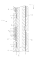
- FIG. 2 is a cross-sectional view of the fuel cell.
- FIG. 3 is a partially enlarged view of FIG. 2.
- FIG. 1 is a perspective view of a fuel cell 10.
- FIG. 2 is a cross-sectional view of the fuel cell 10 taken along a gas flow path 21, which will be described later.
- the fuel cell 10 includes a support substrate 20 and a plurality of power generation element sections 30.
- the support substrate 20 is formed into a flat plate shape.
- the dimension in the length direction (x-axis direction) is longer than the dimension in the width direction (y-axis direction), but the dimension in the width direction may be longer than the length direction. .
- the support substrate 20 has a first main surface S1 and a second main surface T1.
- the first main surface S1 and the second main surface T1 face oppositely to each other in the thickness direction (z-axis direction) of the support substrate 20.
- the first main surface S1 and the second main surface T1 support each power generation element section 30.
- the support substrate 20 is made of a porous material that does not have electronic conductivity.
- the support substrate 20 is made of, for example, CSZ (calcia stabilized zirconia).
- the support substrate 20 may be composed of NiO (nickel oxide) and YSZ (yttria stabilized zirconia), or may be composed of NiO (nickel oxide) and Y 2 O 3 (yttria).
- the porosity of the support substrate 20 can be, for example, 20% or more and 60% or less. In this specification, porosity is the ratio of the area of the gas phase to the total area of the solid phase and gas phase in cross-sectional observation using a SEM (scanning electron microscope).
- a plurality of gas channels 21 are formed inside the support substrate 20.
- Each gas flow path 21 is supplied with fuel gas such as hydrogen gas.
- each gas flow path 21 extends in the length direction (x-axis direction) within the support substrate 20.
- Each gas flow path 21 penetrates the support substrate 20. It is preferable that each gas flow path 21 is arranged at substantially equal intervals.
- the support substrate 20 is covered with a dense layer 22.
- the dense layer 22 covers a region of the surface of the support substrate 20 that is not covered by each power generation element section 30 .
- the dense layer 22 suppresses the gas diffused within the support substrate 20 from being discharged to the outside.
- the dense layer 22 is made of, for example, MgO (magnesium oxide), CaZrO 3 (calcium zirconate), Y 2 O 3 (yttria), MgAl 2 O 4 (magnesia alumina spinel), CSZ (calcia stabilized zirconia), YSZ (8YSZ).
- the dense layer 22 is denser than the support substrate 20.
- the porosity of the dense layer 22 can be, for example, 0% or more and 7% or less.
- each power generation element section 30 is supported by the first main surface S1 or the second main surface T1 of the support substrate 20.
- the number of power generation element sections 30 arranged on the first main surface S1 and the number of power generation element sections 30 arranged on the second main surface T1 may be the same or different.
- the sizes of the power generating element sections 30 may be the same or different.
- the power generation element sections 30 are arranged at intervals along the length direction (x-axis direction) in which the gas flow path 21 extends. Each power generating element section 30 is electrically connected to each other in series.
- the power generation element section 30 includes a first current collecting section 1 , a hydrogen electrode 2 , an electrolyte 3 , a reaction prevention layer 4 , an oxygen electrode 5 , a second current collecting section 6 , and an interconnector 7 .
- the first current collector 1 is arranged within the recess 23 of the support substrate 20.
- the first current collector 1 has a first recess 11 and a second recess 12 .
- the hydrogen electrode 2 is placed inside the first recess 11 .
- the interconnector 7 is arranged within the second recess 12 .
- the first current collector 1 is made of a porous material having electron conductivity.
- the first current collector 1 can be made of, for example, NiO (nickel oxide) and Y 2 O 3 (yttria).
- the first current collector 1 may be composed of NiO (nickel oxide) and 8YSZ (yttria stabilized zirconia), or may be composed of NiO (nickel oxide) and CSZ (calcia stabilized zirconia). Good too.
- the porosity of the first current collector 1 can be, for example, 10% or more and 50% or less.
- the thickness of the first current collector 1 can be, for example, 50 ⁇ m or more and 500 ⁇ m or less.
- Hydrogen electrode 2 is arranged within first recess 11 of first current collector 1 . Fuel gas is supplied to the hydrogen electrode 2 from the gas flow path 21 via the support substrate 20 and the first current collector 1 . At the hydrogen electrode 2, an electrode reaction expressed by the following formula (1) occurs. H2 + O2- ⁇ H2O +2e -... (1)
- the hydrogen electrode 2 is made of a porous material that has electronic conductivity and ionic conductivity. Hydrogen electrode 2 contains an ion conductive material containing cerium. The porosity of the hydrogen electrode 2 can be, for example, 10% or more and 50% or less. The thickness of the hydrogen electrode 2 can be, for example, more than 8 ⁇ m and less than 30 ⁇ m. The configuration of the hydrogen electrode 2 will be described later.
- the electrolyte 3 is arranged to cover the hydrogen electrode 2. Both ends of the electrolyte 3 in the length direction (x-axis direction) are connected to an interconnector 7 .
- the electrolyte 3 is made of a dense material that has ionic conductivity and no electronic conductivity.
- the electrolyte 3 is composed of, for example, YSZ (8YSZ), LSGM (lanthanum gallate), or the like.
- the electrolyte 3 is denser than the hydrogen electrode 2.
- the porosity of the electrolyte 3 can be, for example, 0% or more and 7% or less.
- the thickness of the electrolyte 3 can be, for example, 3 ⁇ m or more and 50 ⁇ m or less.
- Reaction prevention layer 4 is arranged on electrolyte 3 .
- the reaction prevention layer 4 is arranged at a position corresponding to the hydrogen electrode 2 with the electrolyte 3 interposed therebetween.
- the reaction prevention layer 4 is provided to prevent the constituent materials of the electrolyte 3 and the constituent materials of the oxygen electrode 5 from reacting to form a reaction layer with high electrical resistance.
- the reaction prevention layer 4 can be made of an ion conductive material.
- the porosity of the reaction prevention layer 4 can be, for example, 0.1% or more and 50% or less.
- the thickness of the reaction prevention layer 4 can be, for example, 1 ⁇ m or more and 50 ⁇ m or less.
- Oxygen electrode 5 is placed on reaction prevention layer 4 .
- Oxygen-containing gas for example, air
- Oxygen-containing gas for example, air
- an electrode reaction expressed by the following equation (2) occurs. (1/2) ⁇ O 2 +2e ⁇ ⁇ O 2 ⁇ ...(2)
- the oxygen electrode 5 is made of a porous material having electronic conductivity.
- the porosity of the oxygen electrode 5 can be, for example, 10% or more and 50% or less.
- the thickness of the oxygen electrode 5 can be, for example, 10 ⁇ m or more and 100 ⁇ m or less.
- the second current collector 6 is connected to the oxygen electrode 5 and the interconnector 7.
- the second current collector 6 is made of a porous material having electron conductivity.
- the second current collector 6 may or may not have oxygen ion conductivity.
- the second current collector 6 can be made of, for example, LSCF, LSC, Ag (silver), Ag-Pd (silver-palladium alloy), or the like.
- the porosity of the second current collector 6 can be, for example, 25% or more and 50% or less.
- the thickness of the second current collector 6 can be, for example, 50 ⁇ m or more and 500 ⁇ m or less.
- the interconnector 7 is arranged within the second recess 12 of the first current collector 1 . Both ends of the interconnector 7 in the length direction (x-axis direction) are connected to the electrolyte 3 .
- the interconnector 7 is made of a dense material that has electronic conductivity.
- the interconnector 7 can be made of, for example, LaCrO 3 (lanthanum chromite), (Sr,La)TiO 3 (strontium titanate), or the like.
- the porosity of the interconnector 7 can be, for example, 0% or more and 7% or less.
- the thickness of the interconnector 7 can be, for example, 10 ⁇ m or more and 100 ⁇ m or less.
- FIG. 3 is a partially enlarged view of FIG. 2.
- the hydrogen electrode 2 has a first portion 101 and a second portion 102.
- the first portion 101 is a region of the hydrogen electrode 2 on the side opposite to the electrolyte 3. Specifically, the first portion 101 is a region within 8 ⁇ m from the surface S2 of the hydrogen electrode 2 on the side opposite to the electrolyte 3. Therefore, the thickness of the first portion 101 is 8 ⁇ m. In this embodiment, the first portion 101 is connected to the first current collector 1 .
- the surface S2 of the hydrogen electrode 2 (that is, the interface between the first current collector 1 and the hydrogen electrode 2) is specified by a line where the content of Ce (cerium) is 3%.
- the Ce content is obtained by line analysis using an atomic concentration profile, which will be described later.
- the second portion 102 is a region of the hydrogen electrode 2 on the electrolyte 3 side. Specifically, the second portion 102 is a region of the hydrogen electrode 2 that is more than 8 ⁇ m from the surface S2. That is, the second portion 102 is a region of the hydrogen electrode 2 excluding the first portion 101. The second portion 102 is integrally formed with the first portion 101. In this embodiment, the second portion 102 is connected to the electrolyte 3.
- the ionic conductivity of the first portion 101 is lower than the ionic conductivity of the second portion 102. That is, the electrode reaction resistance of the first portion 101 is greater than the electrode reaction resistance of the second portion 102. Therefore, during operation of the fuel cell 10, the first portion 101 becomes higher in temperature than the second portion 102 due to the heat of reaction. Therefore, when the fuel gas supplied to the hydrogen electrode 2 contains a poisonous substance (for example, silicon, etc.), the poisonous substance can be efficiently adsorbed onto the first portion 101.
- a poisonous substance for example, silicon, etc.
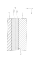
- the ionic conductivity of the first portion 101 is measured as follows. First, in the cross section of the hydrogen electrode 2 along the thickness direction (z-axis direction), the first portion 101 is defined as a region within 8 ⁇ m from the surface S2 on the opposite side to the electrolyte 3. Next, by obtaining elemental mapping of the first portion 101 using an Electron Probe Micro Analyzer (EPMA), the composition of the first portion 101 and the content rate of each composition are specified. Next, pellets to be measured are prepared by mixing the specified composition at the specified content rate and firing (1300° C. for 5 hours). Next, two terminal attachment pellets made of YSZ and fired (1300° C. for 5 hours) are prepared.
- EPMA Electron Probe Micro Analyzer
- the pellet to be measured is sandwiched between two pellets for terminal attachment, and the current wire is bonded to the pellet for terminal attachment with platinum paste, and the potential wire is bonded to the pellet to be measured using platinum paste.
- the ionic conductivity of the pellet to be measured is measured using a four-terminal method. The ionic conductivity of the pellet to be measured thus measured is the ionic conductivity of the first portion 101.
- the ionic conductivity of the second portion 102 is measured in the same way as the ionic conductivity of the first portion 101.
- the first portion 101 and the second portion 102 each contain an ion conductive material containing Ce (cerium) and Ni (nickel).
- the ionic conductivity of the ion conductive material contained in the first portion 101 may be lower than the ionic conductivity of the ion conductive material contained in the second portion 102.
- the ion conductive material contained in the first portion 101 is a solid solution of Y 2 O 3 (yttria), CeO 2 (ceria), and Gd 2 O 3 (gadria) (hereinafter referred to as "Y(Ce, Gd) solid solution”). ), and a solid solution of Y 2 O 3 , CeO 2 and Sm 2 O 3 (Samaria) (hereinafter referred to as "Y(Ce,Sm) solid solution”).
- Y(Ce, Gd) solid solution a solid solution of Y 2 O 3 , CeO 2 and Sm 2 O 3 (Samaria)
- a Y (Ce, Gd) solid solution is suitable as the ion conductive material contained in the first portion 101.
- the Y (Ce, Gd) solid solution refers to one in which Y 2 O 3 , CeO 2 and Gd 2 O 3 are dissolved together to form a uniform solid phase.
- the ion conductive material contained in the second portion 102 includes ceria-based oxide to which a rare earth element is added.
- a ceria-based oxide to which a rare earth element is added is suitable.
- Examples of ceria-based oxides doped with rare earth elements include, but are not limited to, gadolinium-doped ceria (GDC), samarium-doped ceria (SDC), and yttrium-doped ceria (YDC).
- GDC gadolinium-doped ceria
- SDC samarium-doped ceria
- YDC yttrium-doped ceria
- CeO 2 (ceria) doped with an oxide of Gd (gadolinium) of 5 mol % or more and 20 mol % or less can be used.
- the ionic conductivity of the first portion 101 can be adjusted by the composition of the ion conductive material contained in the first portion 101 and the content rate of the ion conductive material.
- the content of the ion conductive material containing Ce in the first portion 101 can be 35 mol% or more and 65 mol% or less.
- the ionic conductivity of the second portion 102 can be adjusted by the composition of the ion conductive material contained in the second portion 102 and the content rate of the ion conductive material.
- the content of the ion conductive material containing Ce in the second portion 102 can be 35 mol% or more and 65 mol% or less.
- the content of the ion conductive material containing Ce in the first portion 101 and the second portion 102 is obtained by line analysis using an atomic concentration profile, that is, elemental mapping using EPMA. Specifically, concentration distribution data of each element is obtained by performing line analysis in the z-axis direction using EPMA in a cross section along the thickness direction (z-axis direction in FIG. 3).
- EPMA is a concept that includes EDS (Energy Dispersive x-ray Spectroscopy).
- the Ni content in the first portion 101 can be 35 mol% or more and 65 mol% or less.
- the Ni content in the second portion 102 can be 35 mol% or more and 65 mol% or less.
- Ni content in the first portion 101 and the second portion 102 is obtained by line analysis using the atomic concentration profile described above.
- Ni is preferably present as metal Ni in a reducing atmosphere supplied with fuel gas, but may be present as NiO when no fuel gas is supplied.
- An electrochemical cell consists of an element with a pair of electrodes arranged so that an electromotive force is generated from the overall redox reaction, and an element that converts chemical energy into electrical energy. It is a generic term.
- electrochemical cells include vertical striped fuel cells, flat plate fuel cells, cylindrical fuel cells, and hydrogen generation cells that utilize the electrolysis reaction of water.
- An example is an electrolytic cell that performs this.
- O 2 - (oxygen ions) are used as carriers, but OH - (hydroxide ions) or protons may be used as carriers.
- the power generation element section 30 is provided with the reaction prevention layer 4, but the reaction prevention layer 4 may not be provided.
- Fuel cell 20 Support substrate 30 Power generation element section 1 First current collecting section 2 Hydrogen electrode 101 First section 102 Second section 3 Electrolyte 4 Reaction prevention layer 5 Oxygen electrode 6 Second current collecting section 7 Interconnector
Landscapes
- Chemical & Material Sciences (AREA)
- Electrochemistry (AREA)
- Engineering & Computer Science (AREA)
- Chemical Kinetics & Catalysis (AREA)
- Metallurgy (AREA)
- Materials Engineering (AREA)
- Organic Chemistry (AREA)
- General Chemical & Material Sciences (AREA)
- Life Sciences & Earth Sciences (AREA)
- Manufacturing & Machinery (AREA)
- Sustainable Development (AREA)
- Sustainable Energy (AREA)
- Inorganic Chemistry (AREA)
- Ceramic Engineering (AREA)
- Fuel Cell (AREA)
Abstract
Dans la présente invention, une cellule de batterie à combustible (10) comprend : une électrode à hydrogène (2) contenant un matériau conducteur d'ions qui comprend du cérium ; une électrode à oxygène (5) ; et un électrolyte (3). L'électrode à hydrogène (2) a une première partie (101) qui est à moins de 8 µm d'une surface (S2) sur le côté à l'opposé de l'électrolyte (3), et une seconde partie (102) qui est à plus de 8 µm de la surface (S2). La conductivité ionique de la première partie (101) est inférieure à la conductivité ionique de la seconde partie (102).
Applications Claiming Priority (2)
| Application Number | Priority Date | Filing Date | Title |
|---|---|---|---|
| JP2022-062957 | 2022-04-05 | ||
| JP2022062957 | 2022-04-05 |
Publications (1)
| Publication Number | Publication Date |
|---|---|
| WO2023195246A1 true WO2023195246A1 (fr) | 2023-10-12 |
Family
ID=88242779
Family Applications (1)
| Application Number | Title | Priority Date | Filing Date |
|---|---|---|---|
| PCT/JP2023/005685 WO2023195246A1 (fr) | 2022-04-05 | 2023-02-17 | Cellule électrochimique |
Country Status (1)
| Country | Link |
|---|---|
| WO (1) | WO2023195246A1 (fr) |
Citations (3)
| Publication number | Priority date | Publication date | Assignee | Title |
|---|---|---|---|---|
| JPH08213029A (ja) * | 1995-02-06 | 1996-08-20 | Fujikura Ltd | 固体電解質型燃料電池の燃料電極 |
| JP2006024545A (ja) * | 2003-11-10 | 2006-01-26 | Mitsubishi Materials Corp | 固体電解質型燃料電池用発電セル |
| JP2019008914A (ja) * | 2017-06-21 | 2019-01-17 | 日本特殊陶業株式会社 | 電気化学セルおよび電気化学スタック |
-
2023
- 2023-02-17 WO PCT/JP2023/005685 patent/WO2023195246A1/fr unknown
Patent Citations (3)
| Publication number | Priority date | Publication date | Assignee | Title |
|---|---|---|---|---|
| JPH08213029A (ja) * | 1995-02-06 | 1996-08-20 | Fujikura Ltd | 固体電解質型燃料電池の燃料電極 |
| JP2006024545A (ja) * | 2003-11-10 | 2006-01-26 | Mitsubishi Materials Corp | 固体電解質型燃料電池用発電セル |
| JP2019008914A (ja) * | 2017-06-21 | 2019-01-17 | 日本特殊陶業株式会社 | 電気化学セルおよび電気化学スタック |
Similar Documents
| Publication | Publication Date | Title |
|---|---|---|
| US7838141B2 (en) | Cerium-modified doped strontium titanate compositions for solid oxide fuel cell anodes and electrodes for other electrochemical devices | |
| US9252447B2 (en) | Composite anode for a solid oxide fuel cell with improved mechanical integrity and increased efficiency | |
| CN105981207B (zh) | 电化学能量转换装置、电池及其负极侧材料 | |
| US5731097A (en) | Solid-electrolyte fuel cell | |
| EP2410598A1 (fr) | Matériau d'électrode et pile à combustible d'oxyde solide le contenant | |
| JP5804894B2 (ja) | 燃料電池セル | |
| CN105359321A (zh) | 用于捕获铬而配置的燃料电池系统 | |
| JP5144236B2 (ja) | 固体酸化物形燃料電池 | |
| JP2011119178A (ja) | 固体酸化物形燃料電池 | |
| JP6348644B2 (ja) | 電気化学セルスタック | |
| JP4374631B2 (ja) | 酸化物イオン混合伝導体とその用途 | |
| EP2530771A1 (fr) | Pile à combustible | |
| KR20190028340A (ko) | 고체산화물 연료 전지 및 이를 포함하는 전지 모듈 | |
| WO2023195246A1 (fr) | Cellule électrochimique | |
| JP5613808B1 (ja) | 燃料電池 | |
| WO2023203870A1 (fr) | Cellule électrochimique | |
| WO2023203875A1 (fr) | Cellule électrochimique | |
| JP5117834B2 (ja) | 固体酸化物形燃料電池 | |
| WO2023195245A1 (fr) | Cellule électrochimique | |
| EP4243128A1 (fr) | Traitement optimisé d'électrodes pour sofc et soec | |
| JP2013191546A (ja) | 固体酸化物型燃料電池 | |
| JPWO2018151193A1 (ja) | 電気化学反応単セルおよび電気化学反応セルスタック | |
| KR102564764B1 (ko) | 전기 화학 장치, 에너지 시스템, 및 고체 산화물형 연료 전지 | |
| JP2001196083A (ja) | 固体電解質型燃料電池 | |
| JP6445988B2 (ja) | 電気化学セルおよび電気化学スタック |
Legal Events
| Date | Code | Title | Description |
|---|---|---|---|
| 121 | Ep: the epo has been informed by wipo that ep was designated in this application |
Ref document number: 23784539 Country of ref document: EP Kind code of ref document: A1 |