WO2023195246A1 - Electrochemical cell - Google Patents
Electrochemical cell Download PDFInfo
- Publication number
- WO2023195246A1 WO2023195246A1 PCT/JP2023/005685 JP2023005685W WO2023195246A1 WO 2023195246 A1 WO2023195246 A1 WO 2023195246A1 JP 2023005685 W JP2023005685 W JP 2023005685W WO 2023195246 A1 WO2023195246 A1 WO 2023195246A1
- Authority
- WO
- WIPO (PCT)
- Prior art keywords
- hydrogen electrode
- electrode
- electrolyte
- current collector
- ionic conductivity
- Prior art date
Links
- UFHFLCQGNIYNRP-UHFFFAOYSA-N Hydrogen Chemical compound [H][H] UFHFLCQGNIYNRP-UHFFFAOYSA-N 0.000 claims abstract description 47
- 239000001257 hydrogen Substances 0.000 claims abstract description 46
- 229910052739 hydrogen Inorganic materials 0.000 claims abstract description 46
- 239000003792 electrolyte Substances 0.000 claims abstract description 26
- 239000001301 oxygen Substances 0.000 claims abstract description 23
- 229910052760 oxygen Inorganic materials 0.000 claims abstract description 23
- QVGXLLKOCUKJST-UHFFFAOYSA-N atomic oxygen Chemical compound [O] QVGXLLKOCUKJST-UHFFFAOYSA-N 0.000 claims abstract description 21
- 239000004020 conductor Substances 0.000 claims abstract description 20
- 229910052684 Cerium Inorganic materials 0.000 claims abstract description 10
- GWXLDORMOJMVQZ-UHFFFAOYSA-N cerium Chemical compound [Ce] GWXLDORMOJMVQZ-UHFFFAOYSA-N 0.000 claims abstract description 6
- CETPSERCERDGAM-UHFFFAOYSA-N ceric oxide Chemical compound O=[Ce]=O CETPSERCERDGAM-UHFFFAOYSA-N 0.000 claims description 12
- 229910000422 cerium(IV) oxide Inorganic materials 0.000 claims description 12
- 239000006104 solid solution Substances 0.000 claims description 10
- 229910052761 rare earth metal Inorganic materials 0.000 claims description 7
- RUDFQVOCFDJEEF-UHFFFAOYSA-N yttrium(III) oxide Inorganic materials [O-2].[O-2].[O-2].[Y+3].[Y+3] RUDFQVOCFDJEEF-UHFFFAOYSA-N 0.000 claims description 5
- 241000357643 Gadoria Species 0.000 claims 1
- 239000000446 fuel Substances 0.000 abstract description 18
- 239000000758 substrate Substances 0.000 description 20
- 150000002500 ions Chemical class 0.000 description 17
- 238000006243 chemical reaction Methods 0.000 description 16
- 239000007789 gas Substances 0.000 description 13
- PXHVJJICTQNCMI-UHFFFAOYSA-N Nickel Chemical compound [Ni] PXHVJJICTQNCMI-UHFFFAOYSA-N 0.000 description 12
- 230000002265 prevention Effects 0.000 description 12
- 229910000480 nickel oxide Inorganic materials 0.000 description 11
- 238000010248 power generation Methods 0.000 description 11
- 229910001233 yttria-stabilized zirconia Inorganic materials 0.000 description 10
- 229910021526 gadolinium-doped ceria Inorganic materials 0.000 description 8
- CPLXHLVBOLITMK-UHFFFAOYSA-N magnesium oxide Inorganic materials [Mg]=O CPLXHLVBOLITMK-UHFFFAOYSA-N 0.000 description 8
- 239000008188 pellet Substances 0.000 description 8
- MCMNRKCIXSYSNV-UHFFFAOYSA-N Zirconium dioxide Chemical compound O=[Zr]=O MCMNRKCIXSYSNV-UHFFFAOYSA-N 0.000 description 6
- 229910002084 calcia-stabilized zirconia Inorganic materials 0.000 description 6
- 238000003411 electrode reaction Methods 0.000 description 6
- 239000000395 magnesium oxide Substances 0.000 description 6
- 239000000126 substance Substances 0.000 description 6
- 229910052688 Gadolinium Inorganic materials 0.000 description 5
- 239000002737 fuel gas Substances 0.000 description 5
- 239000000203 mixture Substances 0.000 description 5
- GNRSAWUEBMWBQH-UHFFFAOYSA-N oxonickel Chemical compound [Ni]=O GNRSAWUEBMWBQH-UHFFFAOYSA-N 0.000 description 5
- 231100000614 poison Toxicity 0.000 description 5
- 230000007096 poisonous effect Effects 0.000 description 5
- 239000011148 porous material Substances 0.000 description 5
- 238000004458 analytical method Methods 0.000 description 4
- AXZKOIWUVFPNLO-UHFFFAOYSA-N magnesium;oxygen(2-) Chemical compound [O-2].[Mg+2] AXZKOIWUVFPNLO-UHFFFAOYSA-N 0.000 description 4
- 239000000463 material Substances 0.000 description 4
- BASFCYQUMIYNBI-UHFFFAOYSA-N platinum Chemical compound [Pt] BASFCYQUMIYNBI-UHFFFAOYSA-N 0.000 description 4
- 230000006866 deterioration Effects 0.000 description 3
- 229910052746 lanthanum Inorganic materials 0.000 description 3
- -1 oxygen ion Chemical class 0.000 description 3
- 239000012071 phase Substances 0.000 description 3
- 229910000859 α-Fe Inorganic materials 0.000 description 3
- 229910017563 LaCrO Inorganic materials 0.000 description 2
- 229910020068 MgAl Inorganic materials 0.000 description 2
- PACGUUNWTMTWCF-UHFFFAOYSA-N [Sr].[La] Chemical compound [Sr].[La] PACGUUNWTMTWCF-UHFFFAOYSA-N 0.000 description 2
- PNEYBMLMFCGWSK-UHFFFAOYSA-N aluminium oxide Inorganic materials [O-2].[O-2].[O-2].[Al+3].[Al+3] PNEYBMLMFCGWSK-UHFFFAOYSA-N 0.000 description 2
- 239000000969 carrier Substances 0.000 description 2
- NFYLSJDPENHSBT-UHFFFAOYSA-N chromium(3+);lanthanum(3+);oxygen(2-) Chemical compound [O-2].[O-2].[O-2].[Cr+3].[La+3] NFYLSJDPENHSBT-UHFFFAOYSA-N 0.000 description 2
- 239000000470 constituent Substances 0.000 description 2
- 238000002149 energy-dispersive X-ray emission spectroscopy Methods 0.000 description 2
- LNTHITQWFMADLM-UHFFFAOYSA-N gallic acid Chemical compound OC(=O)C1=CC(O)=C(O)C(O)=C1 LNTHITQWFMADLM-UHFFFAOYSA-N 0.000 description 2
- FZLIPJUXYLNCLC-UHFFFAOYSA-N lanthanum atom Chemical compound [La] FZLIPJUXYLNCLC-UHFFFAOYSA-N 0.000 description 2
- 238000013507 mapping Methods 0.000 description 2
- 238000012986 modification Methods 0.000 description 2
- 230000004048 modification Effects 0.000 description 2
- 229910052759 nickel Inorganic materials 0.000 description 2
- 229910052697 platinum Inorganic materials 0.000 description 2
- 229910052710 silicon Inorganic materials 0.000 description 2
- 239000010703 silicon Substances 0.000 description 2
- 239000007790 solid phase Substances 0.000 description 2
- 229910052596 spinel Inorganic materials 0.000 description 2
- 239000011029 spinel Substances 0.000 description 2
- 229910052712 strontium Inorganic materials 0.000 description 2
- XLYOFNOQVPJJNP-UHFFFAOYSA-N water Chemical compound O XLYOFNOQVPJJNP-UHFFFAOYSA-N 0.000 description 2
- 229910003026 (La,Sr)(Co,Fe)O3 Inorganic materials 0.000 description 1
- DJOYTAUERRJRAT-UHFFFAOYSA-N 2-(n-methyl-4-nitroanilino)acetonitrile Chemical compound N#CCN(C)C1=CC=C([N+]([O-])=O)C=C1 DJOYTAUERRJRAT-UHFFFAOYSA-N 0.000 description 1
- 229910018921 CoO 3 Inorganic materials 0.000 description 1
- 229910001252 Pd alloy Inorganic materials 0.000 description 1
- QBYHSJRFOXINMH-UHFFFAOYSA-N [Co].[Sr].[La] Chemical compound [Co].[Sr].[La] QBYHSJRFOXINMH-UHFFFAOYSA-N 0.000 description 1
- 229910052963 cobaltite Inorganic materials 0.000 description 1
- 238000005868 electrolysis reaction Methods 0.000 description 1
- 238000010304 firing Methods 0.000 description 1
- UIWYJDYFSGRHKR-UHFFFAOYSA-N gadolinium atom Chemical compound [Gd] UIWYJDYFSGRHKR-UHFFFAOYSA-N 0.000 description 1
- 239000010416 ion conductor Substances 0.000 description 1
- 229910052742 iron Inorganic materials 0.000 description 1
- DOARWPHSJVUWFT-UHFFFAOYSA-N lanthanum nickel Chemical compound [Ni].[La] DOARWPHSJVUWFT-UHFFFAOYSA-N 0.000 description 1
- 229910052751 metal Inorganic materials 0.000 description 1
- 239000002184 metal Substances 0.000 description 1
- 238000000034 method Methods 0.000 description 1
- KDLHZDBZIXYQEI-UHFFFAOYSA-N palladium Substances [Pd] KDLHZDBZIXYQEI-UHFFFAOYSA-N 0.000 description 1
- SWELZOZIOHGSPA-UHFFFAOYSA-N palladium silver Chemical compound [Pd].[Ag] SWELZOZIOHGSPA-UHFFFAOYSA-N 0.000 description 1
- 238000006479 redox reaction Methods 0.000 description 1
- FKTOIHSPIPYAPE-UHFFFAOYSA-N samarium(iii) oxide Chemical compound [O-2].[O-2].[O-2].[Sm+3].[Sm+3] FKTOIHSPIPYAPE-UHFFFAOYSA-N 0.000 description 1
- 239000000523 sample Substances 0.000 description 1
- 229910052709 silver Inorganic materials 0.000 description 1
- 239000004332 silver Substances 0.000 description 1
- VEALVRVVWBQVSL-UHFFFAOYSA-N strontium titanate Chemical compound [Sr+2].[O-][Ti]([O-])=O VEALVRVVWBQVSL-UHFFFAOYSA-N 0.000 description 1
Images

Classifications
-
- C—CHEMISTRY; METALLURGY
- C25—ELECTROLYTIC OR ELECTROPHORETIC PROCESSES; APPARATUS THEREFOR
- C25B—ELECTROLYTIC OR ELECTROPHORETIC PROCESSES FOR THE PRODUCTION OF COMPOUNDS OR NON-METALS; APPARATUS THEREFOR
- C25B1/00—Electrolytic production of inorganic compounds or non-metals
- C25B1/01—Products
- C25B1/02—Hydrogen or oxygen
- C25B1/04—Hydrogen or oxygen by electrolysis of water
-
- C—CHEMISTRY; METALLURGY
- C25—ELECTROLYTIC OR ELECTROPHORETIC PROCESSES; APPARATUS THEREFOR
- C25B—ELECTROLYTIC OR ELECTROPHORETIC PROCESSES FOR THE PRODUCTION OF COMPOUNDS OR NON-METALS; APPARATUS THEREFOR
- C25B11/00—Electrodes; Manufacture thereof not otherwise provided for
- C25B11/04—Electrodes; Manufacture thereof not otherwise provided for characterised by the material
- C25B11/042—Electrodes formed of a single material
- C25B11/047—Ceramics
-
- C—CHEMISTRY; METALLURGY
- C25—ELECTROLYTIC OR ELECTROPHORETIC PROCESSES; APPARATUS THEREFOR
- C25B—ELECTROLYTIC OR ELECTROPHORETIC PROCESSES FOR THE PRODUCTION OF COMPOUNDS OR NON-METALS; APPARATUS THEREFOR
- C25B9/00—Cells or assemblies of cells; Constructional parts of cells; Assemblies of constructional parts, e.g. electrode-diaphragm assemblies; Process-related cell features
- C25B9/17—Cells comprising dimensionally-stable non-movable electrodes; Assemblies of constructional parts thereof
- C25B9/19—Cells comprising dimensionally-stable non-movable electrodes; Assemblies of constructional parts thereof with diaphragms
- C25B9/23—Cells comprising dimensionally-stable non-movable electrodes; Assemblies of constructional parts thereof with diaphragms comprising ion-exchange membranes in or on which electrode material is embedded
-
- H—ELECTRICITY
- H01—ELECTRIC ELEMENTS
- H01M—PROCESSES OR MEANS, e.g. BATTERIES, FOR THE DIRECT CONVERSION OF CHEMICAL ENERGY INTO ELECTRICAL ENERGY
- H01M4/00—Electrodes
- H01M4/86—Inert electrodes with catalytic activity, e.g. for fuel cells
-
- H—ELECTRICITY
- H01—ELECTRIC ELEMENTS
- H01M—PROCESSES OR MEANS, e.g. BATTERIES, FOR THE DIRECT CONVERSION OF CHEMICAL ENERGY INTO ELECTRICAL ENERGY
- H01M8/00—Fuel cells; Manufacture thereof
- H01M8/10—Fuel cells with solid electrolytes
- H01M8/12—Fuel cells with solid electrolytes operating at high temperature, e.g. with stabilised ZrO2 electrolyte
- H01M8/1213—Fuel cells with solid electrolytes operating at high temperature, e.g. with stabilised ZrO2 electrolyte characterised by the electrode/electrolyte combination or the supporting material
-
- Y—GENERAL TAGGING OF NEW TECHNOLOGICAL DEVELOPMENTS; GENERAL TAGGING OF CROSS-SECTIONAL TECHNOLOGIES SPANNING OVER SEVERAL SECTIONS OF THE IPC; TECHNICAL SUBJECTS COVERED BY FORMER USPC CROSS-REFERENCE ART COLLECTIONS [XRACs] AND DIGESTS
- Y02—TECHNOLOGIES OR APPLICATIONS FOR MITIGATION OR ADAPTATION AGAINST CLIMATE CHANGE
- Y02E—REDUCTION OF GREENHOUSE GAS [GHG] EMISSIONS, RELATED TO ENERGY GENERATION, TRANSMISSION OR DISTRIBUTION
- Y02E60/00—Enabling technologies; Technologies with a potential or indirect contribution to GHG emissions mitigation
- Y02E60/30—Hydrogen technology
- Y02E60/50—Fuel cells
Definitions
- the present invention relates to an electrochemical cell.
- a fuel cell is known as an example of an electrochemical cell (see, for example, Patent Document 1).
- a fuel cell includes a hydrogen electrode, an oxygen electrode, and an electrolyte disposed between the hydrogen electrode and the oxygen electrode.
- the hydrogen electrode is composed of nickel (Ni), which primarily functions as an electron conductor, and ceria-based oxide containing a solid solution of a rare earth element, which primarily functions as an oxygen ion conductor.
- Gadolinium-doped ceria is typical of ceria-based oxides containing rare earth elements in solid solution.
- the hydrogen electrode will deteriorate due to the adhesion of the poisonous substance.
- a poisonous substance for example, silicon, etc.
- An object of the present invention is to provide an electrochemical cell that can suppress deterioration of a hydrogen electrode.
- the electrochemical cell according to the present invention includes a hydrogen electrode containing an ion conductive material containing cerium, an oxygen electrode, and an electrolyte disposed between the hydrogen electrode and the oxygen electrode.
- the hydrogen electrode has a first portion that is within 8 ⁇ m from the surface opposite the electrolyte and a second portion that is more than 8 ⁇ m from the surface.
- the ionic conductivity of the first portion is lower than the ionic conductivity of the second portion.
- FIG. 1 is a perspective view of a fuel cell.
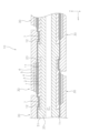
- FIG. 2 is a cross-sectional view of the fuel cell.
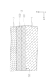
- FIG. 3 is a partially enlarged view of FIG. 2.
- FIG. 1 is a perspective view of a fuel cell 10.
- FIG. 2 is a cross-sectional view of the fuel cell 10 taken along a gas flow path 21, which will be described later.
- the fuel cell 10 includes a support substrate 20 and a plurality of power generation element sections 30.
- the support substrate 20 is formed into a flat plate shape.
- the dimension in the length direction (x-axis direction) is longer than the dimension in the width direction (y-axis direction), but the dimension in the width direction may be longer than the length direction. .
- the support substrate 20 has a first main surface S1 and a second main surface T1.
- the first main surface S1 and the second main surface T1 face oppositely to each other in the thickness direction (z-axis direction) of the support substrate 20.
- the first main surface S1 and the second main surface T1 support each power generation element section 30.
- the support substrate 20 is made of a porous material that does not have electronic conductivity.
- the support substrate 20 is made of, for example, CSZ (calcia stabilized zirconia).
- the support substrate 20 may be composed of NiO (nickel oxide) and YSZ (yttria stabilized zirconia), or may be composed of NiO (nickel oxide) and Y 2 O 3 (yttria).
- the porosity of the support substrate 20 can be, for example, 20% or more and 60% or less. In this specification, porosity is the ratio of the area of the gas phase to the total area of the solid phase and gas phase in cross-sectional observation using a SEM (scanning electron microscope).
- a plurality of gas channels 21 are formed inside the support substrate 20.
- Each gas flow path 21 is supplied with fuel gas such as hydrogen gas.
- each gas flow path 21 extends in the length direction (x-axis direction) within the support substrate 20.
- Each gas flow path 21 penetrates the support substrate 20. It is preferable that each gas flow path 21 is arranged at substantially equal intervals.
- the support substrate 20 is covered with a dense layer 22.
- the dense layer 22 covers a region of the surface of the support substrate 20 that is not covered by each power generation element section 30 .
- the dense layer 22 suppresses the gas diffused within the support substrate 20 from being discharged to the outside.
- the dense layer 22 is made of, for example, MgO (magnesium oxide), CaZrO 3 (calcium zirconate), Y 2 O 3 (yttria), MgAl 2 O 4 (magnesia alumina spinel), CSZ (calcia stabilized zirconia), YSZ (8YSZ).
- the dense layer 22 is denser than the support substrate 20.
- the porosity of the dense layer 22 can be, for example, 0% or more and 7% or less.
- each power generation element section 30 is supported by the first main surface S1 or the second main surface T1 of the support substrate 20.
- the number of power generation element sections 30 arranged on the first main surface S1 and the number of power generation element sections 30 arranged on the second main surface T1 may be the same or different.
- the sizes of the power generating element sections 30 may be the same or different.
- the power generation element sections 30 are arranged at intervals along the length direction (x-axis direction) in which the gas flow path 21 extends. Each power generating element section 30 is electrically connected to each other in series.
- the power generation element section 30 includes a first current collecting section 1 , a hydrogen electrode 2 , an electrolyte 3 , a reaction prevention layer 4 , an oxygen electrode 5 , a second current collecting section 6 , and an interconnector 7 .
- the first current collector 1 is arranged within the recess 23 of the support substrate 20.
- the first current collector 1 has a first recess 11 and a second recess 12 .
- the hydrogen electrode 2 is placed inside the first recess 11 .
- the interconnector 7 is arranged within the second recess 12 .
- the first current collector 1 is made of a porous material having electron conductivity.
- the first current collector 1 can be made of, for example, NiO (nickel oxide) and Y 2 O 3 (yttria).
- the first current collector 1 may be composed of NiO (nickel oxide) and 8YSZ (yttria stabilized zirconia), or may be composed of NiO (nickel oxide) and CSZ (calcia stabilized zirconia). Good too.
- the porosity of the first current collector 1 can be, for example, 10% or more and 50% or less.
- the thickness of the first current collector 1 can be, for example, 50 ⁇ m or more and 500 ⁇ m or less.
- Hydrogen electrode 2 is arranged within first recess 11 of first current collector 1 . Fuel gas is supplied to the hydrogen electrode 2 from the gas flow path 21 via the support substrate 20 and the first current collector 1 . At the hydrogen electrode 2, an electrode reaction expressed by the following formula (1) occurs. H2 + O2- ⁇ H2O +2e -... (1)
- the hydrogen electrode 2 is made of a porous material that has electronic conductivity and ionic conductivity. Hydrogen electrode 2 contains an ion conductive material containing cerium. The porosity of the hydrogen electrode 2 can be, for example, 10% or more and 50% or less. The thickness of the hydrogen electrode 2 can be, for example, more than 8 ⁇ m and less than 30 ⁇ m. The configuration of the hydrogen electrode 2 will be described later.
- the electrolyte 3 is arranged to cover the hydrogen electrode 2. Both ends of the electrolyte 3 in the length direction (x-axis direction) are connected to an interconnector 7 .
- the electrolyte 3 is made of a dense material that has ionic conductivity and no electronic conductivity.
- the electrolyte 3 is composed of, for example, YSZ (8YSZ), LSGM (lanthanum gallate), or the like.
- the electrolyte 3 is denser than the hydrogen electrode 2.
- the porosity of the electrolyte 3 can be, for example, 0% or more and 7% or less.
- the thickness of the electrolyte 3 can be, for example, 3 ⁇ m or more and 50 ⁇ m or less.
- Reaction prevention layer 4 is arranged on electrolyte 3 .
- the reaction prevention layer 4 is arranged at a position corresponding to the hydrogen electrode 2 with the electrolyte 3 interposed therebetween.
- the reaction prevention layer 4 is provided to prevent the constituent materials of the electrolyte 3 and the constituent materials of the oxygen electrode 5 from reacting to form a reaction layer with high electrical resistance.
- the reaction prevention layer 4 can be made of an ion conductive material.
- the porosity of the reaction prevention layer 4 can be, for example, 0.1% or more and 50% or less.
- the thickness of the reaction prevention layer 4 can be, for example, 1 ⁇ m or more and 50 ⁇ m or less.
- Oxygen electrode 5 is placed on reaction prevention layer 4 .
- Oxygen-containing gas for example, air
- Oxygen-containing gas for example, air
- an electrode reaction expressed by the following equation (2) occurs. (1/2) ⁇ O 2 +2e ⁇ ⁇ O 2 ⁇ ...(2)
- the oxygen electrode 5 is made of a porous material having electronic conductivity.
- the porosity of the oxygen electrode 5 can be, for example, 10% or more and 50% or less.
- the thickness of the oxygen electrode 5 can be, for example, 10 ⁇ m or more and 100 ⁇ m or less.
- the second current collector 6 is connected to the oxygen electrode 5 and the interconnector 7.
- the second current collector 6 is made of a porous material having electron conductivity.
- the second current collector 6 may or may not have oxygen ion conductivity.
- the second current collector 6 can be made of, for example, LSCF, LSC, Ag (silver), Ag-Pd (silver-palladium alloy), or the like.
- the porosity of the second current collector 6 can be, for example, 25% or more and 50% or less.
- the thickness of the second current collector 6 can be, for example, 50 ⁇ m or more and 500 ⁇ m or less.
- the interconnector 7 is arranged within the second recess 12 of the first current collector 1 . Both ends of the interconnector 7 in the length direction (x-axis direction) are connected to the electrolyte 3 .
- the interconnector 7 is made of a dense material that has electronic conductivity.
- the interconnector 7 can be made of, for example, LaCrO 3 (lanthanum chromite), (Sr,La)TiO 3 (strontium titanate), or the like.
- the porosity of the interconnector 7 can be, for example, 0% or more and 7% or less.
- the thickness of the interconnector 7 can be, for example, 10 ⁇ m or more and 100 ⁇ m or less.
- FIG. 3 is a partially enlarged view of FIG. 2.
- the hydrogen electrode 2 has a first portion 101 and a second portion 102.
- the first portion 101 is a region of the hydrogen electrode 2 on the side opposite to the electrolyte 3. Specifically, the first portion 101 is a region within 8 ⁇ m from the surface S2 of the hydrogen electrode 2 on the side opposite to the electrolyte 3. Therefore, the thickness of the first portion 101 is 8 ⁇ m. In this embodiment, the first portion 101 is connected to the first current collector 1 .
- the surface S2 of the hydrogen electrode 2 (that is, the interface between the first current collector 1 and the hydrogen electrode 2) is specified by a line where the content of Ce (cerium) is 3%.
- the Ce content is obtained by line analysis using an atomic concentration profile, which will be described later.
- the second portion 102 is a region of the hydrogen electrode 2 on the electrolyte 3 side. Specifically, the second portion 102 is a region of the hydrogen electrode 2 that is more than 8 ⁇ m from the surface S2. That is, the second portion 102 is a region of the hydrogen electrode 2 excluding the first portion 101. The second portion 102 is integrally formed with the first portion 101. In this embodiment, the second portion 102 is connected to the electrolyte 3.
- the ionic conductivity of the first portion 101 is lower than the ionic conductivity of the second portion 102. That is, the electrode reaction resistance of the first portion 101 is greater than the electrode reaction resistance of the second portion 102. Therefore, during operation of the fuel cell 10, the first portion 101 becomes higher in temperature than the second portion 102 due to the heat of reaction. Therefore, when the fuel gas supplied to the hydrogen electrode 2 contains a poisonous substance (for example, silicon, etc.), the poisonous substance can be efficiently adsorbed onto the first portion 101.
- a poisonous substance for example, silicon, etc.
- the ionic conductivity of the first portion 101 is measured as follows. First, in the cross section of the hydrogen electrode 2 along the thickness direction (z-axis direction), the first portion 101 is defined as a region within 8 ⁇ m from the surface S2 on the opposite side to the electrolyte 3. Next, by obtaining elemental mapping of the first portion 101 using an Electron Probe Micro Analyzer (EPMA), the composition of the first portion 101 and the content rate of each composition are specified. Next, pellets to be measured are prepared by mixing the specified composition at the specified content rate and firing (1300° C. for 5 hours). Next, two terminal attachment pellets made of YSZ and fired (1300° C. for 5 hours) are prepared.
- EPMA Electron Probe Micro Analyzer
- the pellet to be measured is sandwiched between two pellets for terminal attachment, and the current wire is bonded to the pellet for terminal attachment with platinum paste, and the potential wire is bonded to the pellet to be measured using platinum paste.
- the ionic conductivity of the pellet to be measured is measured using a four-terminal method. The ionic conductivity of the pellet to be measured thus measured is the ionic conductivity of the first portion 101.
- the ionic conductivity of the second portion 102 is measured in the same way as the ionic conductivity of the first portion 101.
- the first portion 101 and the second portion 102 each contain an ion conductive material containing Ce (cerium) and Ni (nickel).
- the ionic conductivity of the ion conductive material contained in the first portion 101 may be lower than the ionic conductivity of the ion conductive material contained in the second portion 102.
- the ion conductive material contained in the first portion 101 is a solid solution of Y 2 O 3 (yttria), CeO 2 (ceria), and Gd 2 O 3 (gadria) (hereinafter referred to as "Y(Ce, Gd) solid solution”). ), and a solid solution of Y 2 O 3 , CeO 2 and Sm 2 O 3 (Samaria) (hereinafter referred to as "Y(Ce,Sm) solid solution”).
- Y(Ce, Gd) solid solution a solid solution of Y 2 O 3 , CeO 2 and Sm 2 O 3 (Samaria)
- a Y (Ce, Gd) solid solution is suitable as the ion conductive material contained in the first portion 101.
- the Y (Ce, Gd) solid solution refers to one in which Y 2 O 3 , CeO 2 and Gd 2 O 3 are dissolved together to form a uniform solid phase.
- the ion conductive material contained in the second portion 102 includes ceria-based oxide to which a rare earth element is added.
- a ceria-based oxide to which a rare earth element is added is suitable.
- Examples of ceria-based oxides doped with rare earth elements include, but are not limited to, gadolinium-doped ceria (GDC), samarium-doped ceria (SDC), and yttrium-doped ceria (YDC).
- GDC gadolinium-doped ceria
- SDC samarium-doped ceria
- YDC yttrium-doped ceria
- CeO 2 (ceria) doped with an oxide of Gd (gadolinium) of 5 mol % or more and 20 mol % or less can be used.
- the ionic conductivity of the first portion 101 can be adjusted by the composition of the ion conductive material contained in the first portion 101 and the content rate of the ion conductive material.
- the content of the ion conductive material containing Ce in the first portion 101 can be 35 mol% or more and 65 mol% or less.
- the ionic conductivity of the second portion 102 can be adjusted by the composition of the ion conductive material contained in the second portion 102 and the content rate of the ion conductive material.
- the content of the ion conductive material containing Ce in the second portion 102 can be 35 mol% or more and 65 mol% or less.
- the content of the ion conductive material containing Ce in the first portion 101 and the second portion 102 is obtained by line analysis using an atomic concentration profile, that is, elemental mapping using EPMA. Specifically, concentration distribution data of each element is obtained by performing line analysis in the z-axis direction using EPMA in a cross section along the thickness direction (z-axis direction in FIG. 3).
- EPMA is a concept that includes EDS (Energy Dispersive x-ray Spectroscopy).
- the Ni content in the first portion 101 can be 35 mol% or more and 65 mol% or less.
- the Ni content in the second portion 102 can be 35 mol% or more and 65 mol% or less.
- Ni content in the first portion 101 and the second portion 102 is obtained by line analysis using the atomic concentration profile described above.
- Ni is preferably present as metal Ni in a reducing atmosphere supplied with fuel gas, but may be present as NiO when no fuel gas is supplied.
- An electrochemical cell consists of an element with a pair of electrodes arranged so that an electromotive force is generated from the overall redox reaction, and an element that converts chemical energy into electrical energy. It is a generic term.
- electrochemical cells include vertical striped fuel cells, flat plate fuel cells, cylindrical fuel cells, and hydrogen generation cells that utilize the electrolysis reaction of water.
- An example is an electrolytic cell that performs this.
- O 2 - (oxygen ions) are used as carriers, but OH - (hydroxide ions) or protons may be used as carriers.
- the power generation element section 30 is provided with the reaction prevention layer 4, but the reaction prevention layer 4 may not be provided.
- Fuel cell 20 Support substrate 30 Power generation element section 1 First current collecting section 2 Hydrogen electrode 101 First section 102 Second section 3 Electrolyte 4 Reaction prevention layer 5 Oxygen electrode 6 Second current collecting section 7 Interconnector
Landscapes
- Chemical & Material Sciences (AREA)
- Engineering & Computer Science (AREA)
- Chemical Kinetics & Catalysis (AREA)
- Electrochemistry (AREA)
- Organic Chemistry (AREA)
- Metallurgy (AREA)
- Materials Engineering (AREA)
- General Chemical & Material Sciences (AREA)
- Sustainable Development (AREA)
- Sustainable Energy (AREA)
- Life Sciences & Earth Sciences (AREA)
- Manufacturing & Machinery (AREA)
- Ceramic Engineering (AREA)
- Inorganic Chemistry (AREA)
- Fuel Cell (AREA)
Abstract
In the present invention, a fuel battery cell (10) comprises: a hydrogen electrode (2) containing an ion-conducting material that includes cerium; an oxygen electrode (5); and an electrolyte (3). The hydrogen electrode (2) has a first portion (101) that is within 8 μm from a surface (S2) on the side away from the electrolyte (3), and a second portion (102) that is greater than 8 μm from the surface (S2). The ion conductivity of the first portion (101) is lower than the ion conductivity of the second portion (102).
Description
本発明は、電気化学セルに関するものである。
The present invention relates to an electrochemical cell.
電気化学セルの一例として燃料電池が知られている(例えば、特許文献1参照)。燃料電池は、水素極と、酸素極と、水素極及び酸素極の間に配置される電解質とを備える。水素極は、電子伝導体として主に機能するニッケル(Ni)と、酸素イオン伝導体として主に機能する希土類元素が固溶したセリア系酸化物とによって構成される。希土類元素が固溶したセリア系酸化物としては、ガドリニウムドープセリアが代表的である。
A fuel cell is known as an example of an electrochemical cell (see, for example, Patent Document 1). A fuel cell includes a hydrogen electrode, an oxygen electrode, and an electrolyte disposed between the hydrogen electrode and the oxygen electrode. The hydrogen electrode is composed of nickel (Ni), which primarily functions as an electron conductor, and ceria-based oxide containing a solid solution of a rare earth element, which primarily functions as an oxygen ion conductor. Gadolinium-doped ceria is typical of ceria-based oxides containing rare earth elements in solid solution.
水素極に供給されるガスに被毒物質(例えば、シリコンなど)が含まれている場合、被毒物質の付着によって水素極が劣化してしまう。
If the gas supplied to the hydrogen electrode contains a poisonous substance (for example, silicon, etc.), the hydrogen electrode will deteriorate due to the adhesion of the poisonous substance.
本発明の課題は、水素極の劣化を抑制可能な電気化学セルを提供することである。
An object of the present invention is to provide an electrochemical cell that can suppress deterioration of a hydrogen electrode.
本発明に係る電気化学セルは、セリウムを含むイオン伝導性材料を含有する水素極と、酸素極と、水素極及び酸素極の間に配置される電解質とを備える。水素極は、電解質と反対側の表面から8μm以内の第1部分と、表面から8μm超の第2部分とを有する。第1部分のイオン伝導度は、第2部分のイオン伝導度より低い。
The electrochemical cell according to the present invention includes a hydrogen electrode containing an ion conductive material containing cerium, an oxygen electrode, and an electrolyte disposed between the hydrogen electrode and the oxygen electrode. The hydrogen electrode has a first portion that is within 8 μm from the surface opposite the electrolyte and a second portion that is more than 8 μm from the surface. The ionic conductivity of the first portion is lower than the ionic conductivity of the second portion.
本発明によれば、水素極の劣化を抑制可能な電気化学セルを提供することができる。
According to the present invention, it is possible to provide an electrochemical cell that can suppress deterioration of a hydrogen electrode.
(燃料電池セル10)
電気化学セルの一例として燃料電池セル10について説明する。図1は、燃料電池セル10の斜視図である。図2は、後述するガス流路21に沿って切断した燃料電池セル10の断面図である。 (Fuel cell cell 10)
Afuel cell 10 will be described as an example of an electrochemical cell. FIG. 1 is a perspective view of a fuel cell 10. FIG. 2 is a cross-sectional view of the fuel cell 10 taken along a gas flow path 21, which will be described later.
電気化学セルの一例として燃料電池セル10について説明する。図1は、燃料電池セル10の斜視図である。図2は、後述するガス流路21に沿って切断した燃料電池セル10の断面図である。 (Fuel cell cell 10)
A
図1及び図2に示すように、燃料電池セル10は、支持基板20及び複数の発電素子部30を備える。
As shown in FIGS. 1 and 2, the fuel cell 10 includes a support substrate 20 and a plurality of power generation element sections 30.
[支持基板20]
図1に示すように、支持基板20は、扁平な板状に形成される。本実施形態に係る支持基板20では、長さ方向(x軸方向)の寸法が、幅方向(y軸方向)の寸法より長いが、長さ方向より幅方向の寸法の方が長くてもよい。 [Support board 20]
As shown in FIG. 1, thesupport substrate 20 is formed into a flat plate shape. In the support substrate 20 according to this embodiment, the dimension in the length direction (x-axis direction) is longer than the dimension in the width direction (y-axis direction), but the dimension in the width direction may be longer than the length direction. .
図1に示すように、支持基板20は、扁平な板状に形成される。本実施形態に係る支持基板20では、長さ方向(x軸方向)の寸法が、幅方向(y軸方向)の寸法より長いが、長さ方向より幅方向の寸法の方が長くてもよい。 [Support board 20]
As shown in FIG. 1, the
図2に示すように、支持基板20は、第1主面S1と、第2主面T1とを有する。第1主面S1と第2主面T1とは、支持基板20の厚さ方向(z軸方向)において互いに反対を向いている。第1主面S1及び第2主面T1は、各発電素子部30を支持する。
As shown in FIG. 2, the support substrate 20 has a first main surface S1 and a second main surface T1. The first main surface S1 and the second main surface T1 face oppositely to each other in the thickness direction (z-axis direction) of the support substrate 20. The first main surface S1 and the second main surface T1 support each power generation element section 30.
支持基板20は、電子伝導性を有さない多孔質材料によって構成される。支持基板20は、例えば、CSZ(カルシア安定化ジルコニア)によって構成される。或いは、支持基板20は、NiO(酸化ニッケル)とYSZ(イットリア安定化ジルコニア)とによって構成されてもよいし、NiO(酸化ニッケル)とY2O3(イットリア)とによって構成されてもよいし、MgO(酸化マグネシウム)とMgAl2O4(マグネシアアルミナスピネル)とによって構成されてもよい。支持基板20の気孔率は、例えば、20%以上60%以下とすることができる。本明細書において、気孔率とは、SEM(走査電子顕微鏡)を用いた断面観察における固相と気相の総面積に対する気相の面積の割合である。
The support substrate 20 is made of a porous material that does not have electronic conductivity. The support substrate 20 is made of, for example, CSZ (calcia stabilized zirconia). Alternatively, the support substrate 20 may be composed of NiO (nickel oxide) and YSZ (yttria stabilized zirconia), or may be composed of NiO (nickel oxide) and Y 2 O 3 (yttria). , MgO (magnesium oxide) and MgAl 2 O 4 (magnesia alumina spinel). The porosity of the support substrate 20 can be, for example, 20% or more and 60% or less. In this specification, porosity is the ratio of the area of the gas phase to the total area of the solid phase and gas phase in cross-sectional observation using a SEM (scanning electron microscope).
支持基板20の内部には、複数のガス流路21が形成されている。各ガス流路21には、水素ガスなどの燃料ガスが供給される。本実施形態において、各ガス流路21は、支持基板20内を長さ方向(x軸方向)に延びる。各ガス流路21は、支持基板20を貫通する。各ガス流路21は、実質的に等間隔に配置されることが好ましい。
A plurality of gas channels 21 are formed inside the support substrate 20. Each gas flow path 21 is supplied with fuel gas such as hydrogen gas. In this embodiment, each gas flow path 21 extends in the length direction (x-axis direction) within the support substrate 20. Each gas flow path 21 penetrates the support substrate 20. It is preferable that each gas flow path 21 is arranged at substantially equal intervals.
図1に示すように、支持基板20は、緻密層22によって覆われている。緻密層22は、支持基板20の表面のうち各発電素子部30によって覆われていない領域を覆う。緻密層22は、支持基板20内に拡散されたガスが外部に排出されることを抑制する。緻密層22は、例えば、MgO(酸化マグネシウム)、CaZrO3(カルシウムジルコネート)、Y2O3(イットリア)、MgAl2O4(マグネシアアルミナスピネル)CSZ(カルシア安定化ジルコニア)、YSZ(8YSZ)(イットリア安定化ジルコニア)、LSGM(ランタンガレート)、GDC(ガドリニウムドープセリア)又はLaCrO3(ランタンクロマイト)などによって構成される。緻密層22は、支持基板20よりも緻密である。緻密層22の気孔率は、例えば、0%以上7%以下とすることができる。
As shown in FIG. 1, the support substrate 20 is covered with a dense layer 22. The dense layer 22 covers a region of the surface of the support substrate 20 that is not covered by each power generation element section 30 . The dense layer 22 suppresses the gas diffused within the support substrate 20 from being discharged to the outside. The dense layer 22 is made of, for example, MgO (magnesium oxide), CaZrO 3 (calcium zirconate), Y 2 O 3 (yttria), MgAl 2 O 4 (magnesia alumina spinel), CSZ (calcia stabilized zirconia), YSZ (8YSZ). (yttria-stabilized zirconia), LSGM (lanthanum gallate), GDC (gadolinium-doped ceria), or LaCrO 3 (lanthanum chromite). The dense layer 22 is denser than the support substrate 20. The porosity of the dense layer 22 can be, for example, 0% or more and 7% or less.
[発電素子部30]
図1に示すように、各発電素子部30は、支持基板20の第1主面S1又は第2主面T1に支持されている。第1主面S1に配置される発電素子部30の数と第2主面T1に配置される発電素子部30の数とは、互いに同じであってもよいし異なっていてもよい。また、各発電素子部30の大きさは、互いに同じであってもよいし異なっていてもよい。 [Power generation element section 30]
As shown in FIG. 1, each powergeneration element section 30 is supported by the first main surface S1 or the second main surface T1 of the support substrate 20. The number of power generation element sections 30 arranged on the first main surface S1 and the number of power generation element sections 30 arranged on the second main surface T1 may be the same or different. Furthermore, the sizes of the power generating element sections 30 may be the same or different.
図1に示すように、各発電素子部30は、支持基板20の第1主面S1又は第2主面T1に支持されている。第1主面S1に配置される発電素子部30の数と第2主面T1に配置される発電素子部30の数とは、互いに同じであってもよいし異なっていてもよい。また、各発電素子部30の大きさは、互いに同じであってもよいし異なっていてもよい。 [Power generation element section 30]
As shown in FIG. 1, each power
各発電素子部30は、ガス流路21が延びる長さ方向(x軸方向)に沿って間隔をあけて配置される。各発電素子部30は、互いに電気的に直列に接続される。
The power generation element sections 30 are arranged at intervals along the length direction (x-axis direction) in which the gas flow path 21 extends. Each power generating element section 30 is electrically connected to each other in series.
発電素子部30は、第1集電部1、水素極2、電解質3、反応防止層4、酸素極5、第2集電部6、及びインターコネクタ7を備える。
The power generation element section 30 includes a first current collecting section 1 , a hydrogen electrode 2 , an electrolyte 3 , a reaction prevention layer 4 , an oxygen electrode 5 , a second current collecting section 6 , and an interconnector 7 .
第1集電部1は、支持基板20の凹部23内に配置される。第1集電部1は、第1凹部11及び第2凹部12を有する。第1凹部11内には、水素極2が配置される。第2凹部12内には、インターコネクタ7が配置される。
The first current collector 1 is arranged within the recess 23 of the support substrate 20. The first current collector 1 has a first recess 11 and a second recess 12 . The hydrogen electrode 2 is placed inside the first recess 11 . The interconnector 7 is arranged within the second recess 12 .
第1集電部1は、電子伝導性を有する多孔質材料によって構成される。第1集電部1は、例えば、NiO(酸化ニッケル)とY2O3(イットリア)とによって構成することができる。或いは、第1集電部1は、NiO(酸化ニッケル)と8YSZ(イットリア安定化ジルコニア)とによって構成されてもよいし、NiO(酸化ニッケル)とCSZ(カルシア安定化ジルコニア)とによって構成されてもよい。
The first current collector 1 is made of a porous material having electron conductivity. The first current collector 1 can be made of, for example, NiO (nickel oxide) and Y 2 O 3 (yttria). Alternatively, the first current collector 1 may be composed of NiO (nickel oxide) and 8YSZ (yttria stabilized zirconia), or may be composed of NiO (nickel oxide) and CSZ (calcia stabilized zirconia). Good too.
第1集電部1の気孔率は、例えば、10%以上50%以下とすることができる。第1集電部1の厚さは、例えば、50μm以上500μm以下とすることができる。
The porosity of the first current collector 1 can be, for example, 10% or more and 50% or less. The thickness of the first current collector 1 can be, for example, 50 μm or more and 500 μm or less.
水素極2は、第1集電部1の第1凹部11内に配置される。水素極2には、支持基板20及び第1集電部1を介して、ガス流路21から燃料ガスが供給される。水素極2では、次の式(1)で表される電極反応が起こる。
H2+O2-→H2O+2e- …(1) Hydrogen electrode 2 is arranged withinfirst recess 11 of first current collector 1 . Fuel gas is supplied to the hydrogen electrode 2 from the gas flow path 21 via the support substrate 20 and the first current collector 1 . At the hydrogen electrode 2, an electrode reaction expressed by the following formula (1) occurs.
H2 + O2- → H2O +2e -... (1)
H2+O2-→H2O+2e- …(1) Hydrogen electrode 2 is arranged within
H2 + O2- → H2O +2e -... (1)
水素極2は、電子伝導性及びイオン伝導性を有する多孔質材料によって構成される。水素極2は、セリウムを含むイオン伝導性材料を含有する。水素極2の気孔率は、例えば、10%以上50%以下とすることができる。水素極2の厚さは、例えば、8μm超30μm以下とすることができる。水素極2の構成については後述する。
The hydrogen electrode 2 is made of a porous material that has electronic conductivity and ionic conductivity. Hydrogen electrode 2 contains an ion conductive material containing cerium. The porosity of the hydrogen electrode 2 can be, for example, 10% or more and 50% or less. The thickness of the hydrogen electrode 2 can be, for example, more than 8 μm and less than 30 μm. The configuration of the hydrogen electrode 2 will be described later.
電解質3は、水素極2を覆うように配置される。長さ方向(x軸方向)における電解質3の両端部それぞれは、インターコネクタ7に接続される。
The electrolyte 3 is arranged to cover the hydrogen electrode 2. Both ends of the electrolyte 3 in the length direction (x-axis direction) are connected to an interconnector 7 .
電解質3は、イオン伝導性を有し且つ電子伝導性を有さない緻密質材料によって構成される。電解質3は、例えば、YSZ(8YSZ)、LSGM(ランタンガレート)などによって構成される。電解質3は、水素極2よりも緻密である。電解質3の気孔率は、例えば、0%以上7%以下とすることができる。電解質3の厚さは、例えば、3μm以上50μm以下とすることができる。
The electrolyte 3 is made of a dense material that has ionic conductivity and no electronic conductivity. The electrolyte 3 is composed of, for example, YSZ (8YSZ), LSGM (lanthanum gallate), or the like. The electrolyte 3 is denser than the hydrogen electrode 2. The porosity of the electrolyte 3 can be, for example, 0% or more and 7% or less. The thickness of the electrolyte 3 can be, for example, 3 μm or more and 50 μm or less.
反応防止層4は、電解質3上に配置される。反応防止層4は、電解質3を介して水素極2と対応する位置に配置される。反応防止層4は、電解質3の構成材料と酸素極5の構成材料とが反応して電気抵抗の大きい反応層が形成されることを抑制するために設けられている。反応防止層4は、イオン伝導性材料によって構成することができる。反応防止層4は、例えば、GDC=(Ce,Gd)O2(ガドリニウムドープセリア)によって構成することができる。反応防止層4の気孔率は、例えば、0.1%以上50%以下とすることができる。反応防止層4の厚さは、例えば、1μm以上50μm以下とすることができる。
Reaction prevention layer 4 is arranged on electrolyte 3 . The reaction prevention layer 4 is arranged at a position corresponding to the hydrogen electrode 2 with the electrolyte 3 interposed therebetween. The reaction prevention layer 4 is provided to prevent the constituent materials of the electrolyte 3 and the constituent materials of the oxygen electrode 5 from reacting to form a reaction layer with high electrical resistance. The reaction prevention layer 4 can be made of an ion conductive material. The reaction prevention layer 4 can be made of, for example, GDC=(Ce,Gd)O 2 (gadolinium-doped ceria). The porosity of the reaction prevention layer 4 can be, for example, 0.1% or more and 50% or less. The thickness of the reaction prevention layer 4 can be, for example, 1 μm or more and 50 μm or less.
酸素極5は、反応防止層4上に配置される。酸素極5には、第2集電部6を介して、酸素を含むガス(例えば、空気)が供給される。酸素極5では、次の式(2)で表される電極反応が起こる。
(1/2)・O2+2e-→O2- …(2) Oxygen electrode 5 is placed on reaction prevention layer 4 . Oxygen-containing gas (for example, air) is supplied to the oxygen electrode 5 via the second current collector 6 . At the oxygen electrode 5, an electrode reaction expressed by the following equation (2) occurs.
(1/2)・O 2 +2e − →O 2 − …(2)
酸素極5は、電子伝導性を有する多孔質材料によって構成される。酸素極5は、例えば、LSCF=(La,Sr)(Co,Fe)O3(ランタンストロンチウムコバルトフェライト)、LSF=(La,Sr)FeO3(ランタンストロンチウムフェライト)、LNF=La(Ni,Fe)O3(ランタンニッケルフェライト)、LSC=(La,Sr)CoO3(ランタンストロンチウムコバルタイト)等によって構成することができる。酸素極5の気孔率は、例えば、10%以上50%以下とすることができる。酸素極5の厚さは、例えば、10μm以上100μm以下とすることができる。
The oxygen electrode 5 is made of a porous material having electronic conductivity. The oxygen electrode 5 is made of, for example, LSCF=(La,Sr)(Co,Fe)O 3 (lanthanum strontium cobalt ferrite), LSF=(La,Sr)FeO 3 (lanthanum strontium ferrite), LNF=La(Ni,Fe ) O 3 (lanthanum nickel ferrite), LSC=(La,Sr)CoO 3 (lanthanum strontium cobaltite), or the like. The porosity of the oxygen electrode 5 can be, for example, 10% or more and 50% or less. The thickness of the oxygen electrode 5 can be, for example, 10 μm or more and 100 μm or less.
第2集電部6は、酸素極5及びインターコネクタ7に接続される。第2集電部6は、電子伝導性を有する多孔質材料によって構成される。第2集電部6は、酸素イオン伝導性を有していてもよいし、有していなくてもよい。第2集電部6は、例えば、LSCF、LSC、Ag(銀)、Ag-Pd(銀パラジウム合金)等によって構成することができる。第2集電部6の気孔率は、例えば、25%以上50%以下とすることができる。第2集電部6の厚さは、例えば、50μm以上500μm以下とすることができる。
The second current collector 6 is connected to the oxygen electrode 5 and the interconnector 7. The second current collector 6 is made of a porous material having electron conductivity. The second current collector 6 may or may not have oxygen ion conductivity. The second current collector 6 can be made of, for example, LSCF, LSC, Ag (silver), Ag-Pd (silver-palladium alloy), or the like. The porosity of the second current collector 6 can be, for example, 25% or more and 50% or less. The thickness of the second current collector 6 can be, for example, 50 μm or more and 500 μm or less.
インターコネクタ7は、第1集電部1の第2凹部12内に配置される。長さ方向(x軸方向)におけるインターコネクタ7の両端部それぞれは、電解質3に接続される。インターコネクタ7は、電子伝導性を有する緻密質材料によって構成される。インターコネクタ7は、例えば、LaCrO3(ランタンクロマイト)、(Sr,La)TiO3(ストロンチウムチタネート)等によって構成することができる。インターコネクタ7の気孔率は、例えば、0%以上7%以下とすることができる。インターコネクタ7の厚さは、例えば、10μm以上100μm以下とすることができる。
The interconnector 7 is arranged within the second recess 12 of the first current collector 1 . Both ends of the interconnector 7 in the length direction (x-axis direction) are connected to the electrolyte 3 . The interconnector 7 is made of a dense material that has electronic conductivity. The interconnector 7 can be made of, for example, LaCrO 3 (lanthanum chromite), (Sr,La)TiO 3 (strontium titanate), or the like. The porosity of the interconnector 7 can be, for example, 0% or more and 7% or less. The thickness of the interconnector 7 can be, for example, 10 μm or more and 100 μm or less.
(水素極2の構成)
次に、水素極2の構成について説明する。図3は、図2の部分拡大図である。 (Configuration of hydrogen electrode 2)
Next, the configuration of the hydrogen electrode 2 will be explained. FIG. 3 is a partially enlarged view of FIG. 2.
次に、水素極2の構成について説明する。図3は、図2の部分拡大図である。 (Configuration of hydrogen electrode 2)
Next, the configuration of the hydrogen electrode 2 will be explained. FIG. 3 is a partially enlarged view of FIG. 2.
図3に示すように、水素極2は、第1部分101と、第2部分102とを有する。
As shown in FIG. 3, the hydrogen electrode 2 has a first portion 101 and a second portion 102.
第1部分101は、水素極2のうち電解質3と反対側の領域である。具体的には、第1部分101は、水素極2のうち電解質3と反対側の表面S2から8μm以内の領域である。従って、第1部分101の厚さは、8μmである。本実施形態において、第1部分101は、第1集電部1に接続される。
The first portion 101 is a region of the hydrogen electrode 2 on the side opposite to the electrolyte 3. Specifically, the first portion 101 is a region within 8 μm from the surface S2 of the hydrogen electrode 2 on the side opposite to the electrolyte 3. Therefore, the thickness of the first portion 101 is 8 μm. In this embodiment, the first portion 101 is connected to the first current collector 1 .
なお、水素極2の表面S2(すなわち、第1集電部1と水素極2との界面)は、Ce(セリウム)の含有率が3%となるラインによって特定される。Ceの含有率は、後述する原子濃度プロファイルによるライン分析によって得られる。
Note that the surface S2 of the hydrogen electrode 2 (that is, the interface between the first current collector 1 and the hydrogen electrode 2) is specified by a line where the content of Ce (cerium) is 3%. The Ce content is obtained by line analysis using an atomic concentration profile, which will be described later.
第2部分102は、水素極2のうち電解質3側の領域である。具体的には、第2部分102は、水素極2のうち表面S2から8μm超の領域である。すなわち、第2部分102は、水素極2のうち第1部分101を除いた領域である。第2部分102は、第1部分101と一体的に形成される。本実施形態において、第2部分102は、電解質3に接続される。
The second portion 102 is a region of the hydrogen electrode 2 on the electrolyte 3 side. Specifically, the second portion 102 is a region of the hydrogen electrode 2 that is more than 8 μm from the surface S2. That is, the second portion 102 is a region of the hydrogen electrode 2 excluding the first portion 101. The second portion 102 is integrally formed with the first portion 101. In this embodiment, the second portion 102 is connected to the electrolyte 3.
ここで、第1部分101のイオン伝導度は、第2部分102のイオン伝導度より低い。すなわち、第1部分101の電極反応抵抗は、第2部分102の電極反応抵抗より大きい。そのため、燃料電池セル10の作動中、第2部分102に比べて第1部分101の方が反応熱によって高温になる。従って、水素極2に供給される燃料ガスに被毒物質(例えば、シリコンなど)が含まれている場合、第1部分101に被毒物質を効率的に吸着させることができる。よって、水素極2のうち電極反応が活発な三相界面(反応場)を構成する第2部分102に被毒物質が付着することを抑制できるため、水素極2の劣化(例えば、電極反応の低下)を抑制できる。
Here, the ionic conductivity of the first portion 101 is lower than the ionic conductivity of the second portion 102. That is, the electrode reaction resistance of the first portion 101 is greater than the electrode reaction resistance of the second portion 102. Therefore, during operation of the fuel cell 10, the first portion 101 becomes higher in temperature than the second portion 102 due to the heat of reaction. Therefore, when the fuel gas supplied to the hydrogen electrode 2 contains a poisonous substance (for example, silicon, etc.), the poisonous substance can be efficiently adsorbed onto the first portion 101. Therefore, it is possible to suppress the adhesion of poisonous substances to the second portion 102 of the hydrogen electrode 2 that constitutes the three-phase interface (reaction field) where the electrode reaction is active, so that the deterioration of the hydrogen electrode 2 (for example, the electrode reaction decrease) can be suppressed.
第1部分101のイオン伝導度は、次のように測定される。まず、厚さ方向(z軸方向)に沿った水素極2の断面において、電解質3と反対側の表面S2から8μm以内の領域である第1部分101を確定する。次に、EPMA(Electron Probe Micro Analyzer)を用いて第1部分101の元素マッピングを取得することによって、第1部分101の組成と各組成の含有率を特定する。次に、特定された組成を特定された含有率で混合、焼成(1300℃5時間)した測定対象ペレットを作製する。次に、YSZによって構成され、焼成(1300℃5時間)した端子取付け用ペレットを2つ準備する。次に、2つの端子取付け用ペレットで測定対象ペレットを挟み、電流線を端子取付け用ペレットに白金ペーストで接合するとともに、電位線を測定対象ペレットに白金ペーストで接合する。次に、4端子法にて測定対象ペレットのイオン伝導度を測定する。このように測定された測定対象ペレットのイオン伝導度が、第1部分101のイオン伝導度である。
The ionic conductivity of the first portion 101 is measured as follows. First, in the cross section of the hydrogen electrode 2 along the thickness direction (z-axis direction), the first portion 101 is defined as a region within 8 μm from the surface S2 on the opposite side to the electrolyte 3. Next, by obtaining elemental mapping of the first portion 101 using an Electron Probe Micro Analyzer (EPMA), the composition of the first portion 101 and the content rate of each composition are specified. Next, pellets to be measured are prepared by mixing the specified composition at the specified content rate and firing (1300° C. for 5 hours). Next, two terminal attachment pellets made of YSZ and fired (1300° C. for 5 hours) are prepared. Next, the pellet to be measured is sandwiched between two pellets for terminal attachment, and the current wire is bonded to the pellet for terminal attachment with platinum paste, and the potential wire is bonded to the pellet to be measured using platinum paste. Next, the ionic conductivity of the pellet to be measured is measured using a four-terminal method. The ionic conductivity of the pellet to be measured thus measured is the ionic conductivity of the first portion 101.
第2部分102のイオン伝導度は、第1部分101のイオン伝導度と同様に測定される。
The ionic conductivity of the second portion 102 is measured in the same way as the ionic conductivity of the first portion 101.
第1部分101及び第2部分102それぞれは、Ce(セリウム)を含むイオン伝導性材料と、Ni(ニッケル)とを含有する。第1部分101が含有するイオン伝導性材料のイオン電導度は、第2部分102が含有するイオン伝導性材料のイオン電導度より低くてよい。
The first portion 101 and the second portion 102 each contain an ion conductive material containing Ce (cerium) and Ni (nickel). The ionic conductivity of the ion conductive material contained in the first portion 101 may be lower than the ionic conductivity of the ion conductive material contained in the second portion 102.
第1部分101が含有するイオン伝導性材料としては、Y2O3(イットリア)、CeO2(セリア)及びGd2O3(ガドリア)の固溶体(以下、「Y(Ce,Gd)固溶体」という。)や、Y2O3、CeO2及びSm2O3(サマリア)の固溶体(以下、「Y(Ce,Sm)固溶体」という。)などが挙げられる。第1部分101がY(Ce,Gd)固溶体を含有する場合、Y2O3を含有する第1集電部1との熱膨張係数差を小さくすることができるため、熱膨張係数差に起因して第1部分101と第1集電部1との界面付近にクラックが発生することを抑制することができる。よって、第1部分101が含有するイオン伝導性材料としては、Y(Ce,Gd)固溶体が好適である。なお、Y(Ce,Gd)固溶体とは、Y2O3、CeO2及びGd2O3が互いに溶け合って、全体が均一の固相となっているものをいう。
The ion conductive material contained in the first portion 101 is a solid solution of Y 2 O 3 (yttria), CeO 2 (ceria), and Gd 2 O 3 (gadria) (hereinafter referred to as "Y(Ce, Gd) solid solution"). ), and a solid solution of Y 2 O 3 , CeO 2 and Sm 2 O 3 (Samaria) (hereinafter referred to as "Y(Ce,Sm) solid solution"). When the first portion 101 contains a Y (Ce, Gd) solid solution, it is possible to reduce the difference in thermal expansion coefficient with the first current collector 1 containing Y 2 O 3 . Thus, generation of cracks near the interface between the first portion 101 and the first current collector 1 can be suppressed. Therefore, as the ion conductive material contained in the first portion 101, a Y (Ce, Gd) solid solution is suitable. Note that the Y (Ce, Gd) solid solution refers to one in which Y 2 O 3 , CeO 2 and Gd 2 O 3 are dissolved together to form a uniform solid phase.
第2部分102が含有するイオン伝導性材料としては、希土類元素が添加されたセリア系酸化物が挙げられる。希土類元素が添加されたセリア系酸化物を第2部分102が含有する場合、高いイオン導電性と電子伝導性により水素極2の反応抵抗を下げることができる。よって、第2部分102が含有するイオン伝導性材料としては、希土類元素が添加されたセリア系酸化物が好適である。希土類元素が添加されたセリア系酸化物としては、例えば、ガドリニウムドープセリア(GDC)、サマリウムドープセリア(SDC)、イットリウムドープセリア(YDC)などが挙げられるが、これらには限られない。GDCとしては、5mol%以上20mol%以下のGd(ガドリニウム)の酸化物がドープされたCeO2(セリア)を用いることができる。
The ion conductive material contained in the second portion 102 includes ceria-based oxide to which a rare earth element is added. When the second portion 102 contains a ceria-based oxide to which a rare earth element is added, the reaction resistance of the hydrogen electrode 2 can be lowered due to high ionic conductivity and electronic conductivity. Therefore, as the ion conductive material contained in the second portion 102, a ceria-based oxide to which a rare earth element is added is suitable. Examples of ceria-based oxides doped with rare earth elements include, but are not limited to, gadolinium-doped ceria (GDC), samarium-doped ceria (SDC), and yttrium-doped ceria (YDC). As the GDC, CeO 2 (ceria) doped with an oxide of Gd (gadolinium) of 5 mol % or more and 20 mol % or less can be used.
第1部分101のイオン伝導度は、第1部分101が含有するイオン伝導性材料の組成と、イオン伝導性材料の含有率とによって調整することができる。第1部分101におけるCeを含むイオン伝導性材料の含有率は、35mol%以上65mol%以下とすることができる。
The ionic conductivity of the first portion 101 can be adjusted by the composition of the ion conductive material contained in the first portion 101 and the content rate of the ion conductive material. The content of the ion conductive material containing Ce in the first portion 101 can be 35 mol% or more and 65 mol% or less.
第2部分102のイオン伝導度は、第2部分102が含有するイオン伝導性材料の組成と、イオン伝導性材料の含有率とによって調整することができる。第2部分102におけるCeを含むイオン伝導性材料の含有率は、35mol%以上65mol%以下とすることができる。
The ionic conductivity of the second portion 102 can be adjusted by the composition of the ion conductive material contained in the second portion 102 and the content rate of the ion conductive material. The content of the ion conductive material containing Ce in the second portion 102 can be 35 mol% or more and 65 mol% or less.
第1部分101及び第2部分102におけるCeを含むイオン伝導性材料の含有率は、原子濃度プロファイルによるライン分析、すなわちEPMAを用いた元素マッピングによって得られる。具体的には、厚さ方向(図3のz軸方向)に沿った断面において、EPMAを用いてz軸方向にライン分析を行うことにより、各元素の濃度分布データが取得される。なお、EPMAは、EDS(Energy Dispersive x-ray Spectroscopy)を含む概念である。
The content of the ion conductive material containing Ce in the first portion 101 and the second portion 102 is obtained by line analysis using an atomic concentration profile, that is, elemental mapping using EPMA. Specifically, concentration distribution data of each element is obtained by performing line analysis in the z-axis direction using EPMA in a cross section along the thickness direction (z-axis direction in FIG. 3). Note that EPMA is a concept that includes EDS (Energy Dispersive x-ray Spectroscopy).
第1部分101におけるNiの含有率は、35mol%以上65mol%以下とすることができる。第2部分102におけるNiの含有率は、35mol%以上65mol%以下とすることができる。
The Ni content in the first portion 101 can be 35 mol% or more and 65 mol% or less. The Ni content in the second portion 102 can be 35 mol% or more and 65 mol% or less.
第1部分101及び第2部分102におけるNiの含有率は、上述した原子濃度プロファイルによるライン分析によって得られる。Niは、燃料ガスが供給された還元雰囲気において金属Niとして存在していることが好ましいが、燃料ガスが供給されない場合にはNiOとして存在していてもよい。
The Ni content in the first portion 101 and the second portion 102 is obtained by line analysis using the atomic concentration profile described above. Ni is preferably present as metal Ni in a reducing atmosphere supplied with fuel gas, but may be present as NiO when no fuel gas is supplied.
(実施形態の変形例)
以上、本発明の実施形態について説明したが、本発明はこれらに限定されるものではなく、本発明の趣旨を逸脱しない限りにおいて種々の変更が可能である。 (Modified example of embodiment)
Although the embodiments of the present invention have been described above, the present invention is not limited to these, and various changes can be made without departing from the spirit of the present invention.
[変形例1]
上記実施形態では、燃料電池の一例として、いわゆる横縞型の燃料電池セルについて説明したが、電気化学セルはこれに限られない。本発明は、電解質層の両側に水素極と酸素極とが配置された電気化学セルに適用可能である。 [Modification 1]
In the above embodiment, a so-called horizontal stripe type fuel cell has been described as an example of a fuel cell, but the electrochemical cell is not limited to this. The present invention is applicable to an electrochemical cell in which a hydrogen electrode and an oxygen electrode are arranged on both sides of an electrolyte layer.
電気化学セルとは、電気エネルギーを化学エネルギーに変えるため、全体的な酸化還元反応から起電力が生じるように一対の電極が配置された素子と、化学エネルギーを電気エネルギーに変えるための素子との総称である。
An electrochemical cell consists of an element with a pair of electrodes arranged so that an electromotive force is generated from the overall redox reaction, and an element that converts chemical energy into electrical energy. It is a generic term.
電気化学セルとしては、横縞型の燃料電池セルのほか、縦縞型の燃料電池セル、平板型の燃料電池セル、筒型の燃料電池セル、更に、水の電気分解反応を利用して水素の生成を行う電解セルなどが挙げられる。また、上記実施形態では、O2-(酸素イオン)をキャリアとしたが、OH-(水酸化物イオン)やプロトンをキャリアとしてもよい。
In addition to horizontal striped fuel cells, electrochemical cells include vertical striped fuel cells, flat plate fuel cells, cylindrical fuel cells, and hydrogen generation cells that utilize the electrolysis reaction of water. An example is an electrolytic cell that performs this. Furthermore, in the above embodiments, O 2 - (oxygen ions) are used as carriers, but OH - (hydroxide ions) or protons may be used as carriers.
[変形例2]
上記実施形態において、発電素子部30は、反応防止層4を備えることとしたが、反応防止層4を備えていなくてもよい。 [Modification 2]
In the above embodiment, the powergeneration element section 30 is provided with the reaction prevention layer 4, but the reaction prevention layer 4 may not be provided.
上記実施形態において、発電素子部30は、反応防止層4を備えることとしたが、反応防止層4を備えていなくてもよい。 [Modification 2]
In the above embodiment, the power
10 燃料電池セル
20 支持基板
30 発電素子部
1 第1集電部
2 水素極
101 第1部分
102 第2部分
3 電解質
4 反応防止層
5 酸素極
6 第2集電部
7 インターコネクタ 10Fuel cell 20 Support substrate 30 Power generation element section 1 First current collecting section 2 Hydrogen electrode 101 First section 102 Second section 3 Electrolyte 4 Reaction prevention layer 5 Oxygen electrode 6 Second current collecting section 7 Interconnector
20 支持基板
30 発電素子部
1 第1集電部
2 水素極
101 第1部分
102 第2部分
3 電解質
4 反応防止層
5 酸素極
6 第2集電部
7 インターコネクタ 10
Claims (2)
- セリウムを含むイオン伝導性材料を含有する水素極と、
酸素極と、
前記水素極及び前記酸素極の間に配置される電解質と、
を備え、
前記水素極は、前記電解質と反対側の表面から8μm以内の第1部分と、前記表面から8μm超の第2部分とを有し、
前記第1部分のイオン伝導度は、前記第2部分のイオン伝導度より低い、
電気化学セル。 a hydrogen electrode containing an ion conductive material containing cerium;
an oxygen electrode,
an electrolyte disposed between the hydrogen electrode and the oxygen electrode;
Equipped with
The hydrogen electrode has a first portion that is within 8 μm from the surface opposite to the electrolyte, and a second portion that is more than 8 μm from the surface,
The ionic conductivity of the first portion is lower than the ionic conductivity of the second portion.
electrochemical cell. - 前記第1部分は、イットリア、セリア及びガドリアの固溶体を含有し、
前記第2部分は、希土類元素が添加されたセリア系酸化物を含有する、
請求項1に記載の電気化学セル。 The first portion contains a solid solution of yttria, ceria and gadoria,
The second portion contains a ceria-based oxide to which a rare earth element is added.
An electrochemical cell according to claim 1.
Priority Applications (1)
| Application Number | Priority Date | Filing Date | Title |
|---|---|---|---|
| JP2024514170A JPWO2023195246A1 (en) | 2022-04-05 | 2023-02-17 |
Applications Claiming Priority (2)
| Application Number | Priority Date | Filing Date | Title |
|---|---|---|---|
| JP2022-062957 | 2022-04-05 | ||
| JP2022062957 | 2022-04-05 |
Publications (1)
| Publication Number | Publication Date |
|---|---|
| WO2023195246A1 true WO2023195246A1 (en) | 2023-10-12 |
Family
ID=88242779
Family Applications (1)
| Application Number | Title | Priority Date | Filing Date |
|---|---|---|---|
| PCT/JP2023/005685 WO2023195246A1 (en) | 2022-04-05 | 2023-02-17 | Electrochemical cell |
Country Status (2)
| Country | Link |
|---|---|
| JP (1) | JPWO2023195246A1 (en) |
| WO (1) | WO2023195246A1 (en) |
Citations (3)
| Publication number | Priority date | Publication date | Assignee | Title |
|---|---|---|---|---|
| JPH08213029A (en) * | 1995-02-06 | 1996-08-20 | Fujikura Ltd | Fuel electrode of solid electrolyte fuel cell |
| JP2006024545A (en) * | 2003-11-10 | 2006-01-26 | Mitsubishi Materials Corp | Power generation cell for solid electrolyte fuel battery |
| JP2019008914A (en) * | 2017-06-21 | 2019-01-17 | 日本特殊陶業株式会社 | Electrochemical cell and electrochemical stack |
-
2023
- 2023-02-17 WO PCT/JP2023/005685 patent/WO2023195246A1/en unknown
- 2023-02-17 JP JP2024514170A patent/JPWO2023195246A1/ja active Pending
Patent Citations (3)
| Publication number | Priority date | Publication date | Assignee | Title |
|---|---|---|---|---|
| JPH08213029A (en) * | 1995-02-06 | 1996-08-20 | Fujikura Ltd | Fuel electrode of solid electrolyte fuel cell |
| JP2006024545A (en) * | 2003-11-10 | 2006-01-26 | Mitsubishi Materials Corp | Power generation cell for solid electrolyte fuel battery |
| JP2019008914A (en) * | 2017-06-21 | 2019-01-17 | 日本特殊陶業株式会社 | Electrochemical cell and electrochemical stack |
Also Published As
| Publication number | Publication date |
|---|---|
| JPWO2023195246A1 (en) | 2023-10-12 |
Similar Documents
| Publication | Publication Date | Title |
|---|---|---|
| US7838141B2 (en) | Cerium-modified doped strontium titanate compositions for solid oxide fuel cell anodes and electrodes for other electrochemical devices | |
| CN105981207B (en) | Electrochemical energy conversion equipment, battery and its negative side material | |
| US9252447B2 (en) | Composite anode for a solid oxide fuel cell with improved mechanical integrity and increased efficiency | |
| US5731097A (en) | Solid-electrolyte fuel cell | |
| EP2410598A1 (en) | Electrode Material and Solid Oxide Fuel Cell Containing the Electrode Material | |
| JP5804894B2 (en) | Fuel cell | |
| JP5144236B2 (en) | Solid oxide fuel cell | |
| JP2011119178A (en) | Solid oxide fuel cell | |
| JP6348644B2 (en) | Electrochemical cell stack | |
| JP4374631B2 (en) | Oxide ion mixed conductor and its application | |
| EP2530771A1 (en) | Fuel cell | |
| KR20190028340A (en) | Solid oxide fuel cell and a battery module comprising the same | |
| WO2023195246A1 (en) | Electrochemical cell | |
| JPWO2018151193A1 (en) | Electrochemical reaction cell and electrochemical reaction cell stack | |
| KR102564764B1 (en) | Electrochemical devices, energy systems, and solid oxide fuel cells | |
| JP5613808B1 (en) | Fuel cell | |
| WO2023203870A1 (en) | Electrochemical cell | |
| WO2023203875A1 (en) | Electrochemical cell | |
| JP5117834B2 (en) | Solid oxide fuel cell | |
| WO2023195245A1 (en) | Electrochemical cell | |
| EP4243128A1 (en) | Optimized processing of electrodes for sofc and soec | |
| JP2013191546A (en) | Solid oxide fuel cell | |
| JP2001196083A (en) | Solid electrolyte fuel cell | |
| JP6445988B2 (en) | Electrochemical cell and electrochemical stack | |
| Möller et al. | Long-Term Degradation and Poisoning Effects of Ni-YSZ| YSZ| GDC| PSC in Electrolysis Mode |
Legal Events
| Date | Code | Title | Description |
|---|---|---|---|
| 121 | Ep: the epo has been informed by wipo that ep was designated in this application |
Ref document number: 23784539 Country of ref document: EP Kind code of ref document: A1 |