WO2023191058A1 - 医療用マーカー - Google Patents
医療用マーカー Download PDFInfo
- Publication number
- WO2023191058A1 WO2023191058A1 PCT/JP2023/013568 JP2023013568W WO2023191058A1 WO 2023191058 A1 WO2023191058 A1 WO 2023191058A1 JP 2023013568 W JP2023013568 W JP 2023013568W WO 2023191058 A1 WO2023191058 A1 WO 2023191058A1
- Authority
- WO
- WIPO (PCT)
- Prior art keywords
- distal end
- medical marker
- medical
- hollow organ
- fluorescent
- Prior art date
- Legal status (The legal status is an assumption and is not a legal conclusion. Google has not performed a legal analysis and makes no representation as to the accuracy of the status listed.)
- Ceased
Links
Images









Classifications
-
- A—HUMAN NECESSITIES
- A61—MEDICAL OR VETERINARY SCIENCE; HYGIENE
- A61B—DIAGNOSIS; SURGERY; IDENTIFICATION
- A61B90/00—Instruments, implements or accessories specially adapted for surgery or diagnosis and not covered by any of the groups A61B1/00 - A61B50/00, e.g. for luxation treatment or for protecting wound edges
- A61B90/90—Identification means for patients or instruments, e.g. tags
Definitions
- the present invention relates to a medical marker that can be inserted into a hollow organ using, for example, an endoscope and used as a marker whose position can be visually recognized from outside the hollow organ.
- diseases such as cancer of the gastrointestinal tract, such as the esophagus, stomach, and large intestine, mainly develop and progress from the mucous membrane of the gastrointestinal tract.
- lung cancer primarily originates from the tracheal mucosa
- bladder cancer primarily originates and progresses from the bladder mucosa. Therefore, in order to confirm the diagnosis of diseases in hollow organs such as the gastrointestinal tract, trachea, and bladder, it is essential to insert an endoscope into the hollow organs, observe the mucous membranes, and biopsy the affected tissues. It has become. Then, based on the definitive diagnosis, the affected tissue is surgically removed as necessary.
- Patent Document 1 describes a pair of arm plate parts that open into a substantially V-shape with elasticity, a claw part formed at each tip of the arm plate part, and a claw part formed on each tip of the arm plate part, and a pair of arm plate parts that extend along the longitudinal direction of the pair of arm plate parts. It has a tightening ring that is movably attached to the arm plate and closes the pair of arm plates by moving it in the direction of the claw, and irradiates the outer surface of at least one of the claws with excitation light.
- a clip-shaped medical marker is described that includes a fluorescent member containing a fluorescent dye that emits fluorescence in a predetermined wavelength range, and a reflective material that reflects at least one of excitation light and fluorescence.
- Patent Document 1 The medical marker described in Patent Document 1 can be easily attached to the inner wall of a hollow organ due to its clip shape, and a fluorescent member and a reflective material are arranged at a position that penetrates into the inner wall of the hollow organ. Since fluorescence can be visually recognized from the outside of the hollow organ, it is useful because the attachment position can be easily specified, but there is a problem that the gripping force of the clip is not necessarily strong.
- a medical fluorescent marker needs to be attached to the vicinity of the affected area in a hollow organ before surgery so that the location of the affected area can be determined and left in place until the time of surgery.
- the medical marker described in Patent Document 1 has the problem that the gripping force of the clip is not necessarily strong, so the period that it can be left in the body is not necessarily long (for example, about 3 days). In the medical field, there is a demand for medical markers that can be left in the body for longer and more reliably.
- the present invention has been made in view of the above-mentioned problems, and an object of the present invention is to provide a medical marker that has excellent attachment stability and can be indwelled for an extended period of time, and has excellent visibility from the outside of a hollow organ. With the goal.
- the medical marker according to the present invention is a medical marker that is indwelled in a hollow organ in the body, and includes a cylindrical base material constituting a proximal end portion and a distal end portion.
- the distal end portion is integrally formed with a coil member formed to extend while being spirally wound around the axial direction, and the distal end portion is irradiated with a predetermined wavelength of excitation light. It is characterized in that a phosphor containing a fluorescent dye that emits fluorescence in the area is arranged.
- the distal end of the medical marker is formed of a coil member formed to extend while being spirally wound around the axial direction, and the distal end is provided with fluorescent light.
- a phosphor containing a dye is arranged. This allows the coil member to penetrate inside the inner wall of the hollow organ while rotating, providing a medical marker with excellent attachment stability to the inner wall of the hollow organ and an improved indwelling period. can do.
- the fluorescent substance is placed near the inner wall of the hollow organ, it becomes possible to identify the position of the medical marker by visually recognizing the fluorescence emitted by the fluorescent substance, improving visibility from the outside of the hollow organ. It can provide excellent medical markers.
- At least a portion or the entirety of the coil member may be constituted by the fluorescent substance.
- the coil member itself that penetrates inside the inner wall of the hollow organ is made of fluorescent substance, when the medical marker is attached to the inner wall of the hollow organ, the fluorescent dye containing fluorescent A medical marker that can be placed inside the inner wall of a hollow organ and has excellent visibility from outside the hollow organ can be provided.
- the fluorescent member at least partially or entirely made of the fluorescent substance is provided to extend in the axial direction in the inner cavity formed by the coil member. It may be.
- the fluorescent member made of fluorescent substance is placed near the inner wall of the hollow organ, so that it can be seen from the outside of the hollow organ. It is possible to provide a medical marker with excellent visibility. Further, by providing a fluorescent member as a separate member of the coil member, the coil member can be made of metal or the like, and the stability of attachment of the medical marker can be maintained.
- the distal end of the fluorescent member may be formed to become thinner toward the distal end side.
- the fluorescent member when the medical marker is attached to the inner wall of the hollow organ, the fluorescent member can penetrate inside the inner wall of the hollow organ. It is possible to provide a medical marker with excellent visibility from the outside of a hollow organ.
- the distal end of the coil member may be formed so that it becomes thinner toward the distal end side.
- the distal end of the coil member pierces the inner wall of the hollow organ, and it is possible to improve the ability to penetrate into the inner wall of the hollow organ.
- the base material is removably connected to the distal end of the shaft member capable of transmitting torque, and the base material and the The coil member may be configured to rotate.
- the medical marker including the base material and the coil member can be rotated, and the coil member can penetrate inside the inner wall of the hollow organ.
- FIG. 1 is an overall view of a delivery system used to indwell a medical marker in a patient's body in a first embodiment of the present invention.
- FIG. FIG. 2 is an enlarged view of the vicinity of the distal end of the delivery system shown in FIG. 1, and is a diagram showing the vicinity of the medical marker in the first embodiment of the present invention.
- FIG. 3 is a diagram showing a state in which the medical marker in the first embodiment of the present invention is exposed from the distal end of the outer tube.
- FIG. 3 is a diagram showing a state in which the medical marker according to the first embodiment of the present invention is disconnected from the engagement portion disposed at the distal end of the shaft member.
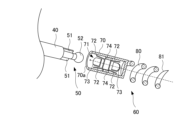
- FIG. 5 is a perspective view of the state shown in FIG. 4; In the perspective view shown in FIG.
- FIG. 5 is a diagram showing the inside of the medical marker.
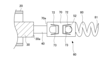
- FIG. 3 is a diagram showing a medical marker according to the first embodiment of the present invention and a state in which the medical marker is connected to an engaging portion disposed at the distal end of the shaft member.
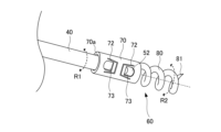
- FIG. 8 is a perspective view of the state shown in FIG. 7; In the perspective view shown in FIG. 8, the medical marker is drawn in cross section and is a diagram schematically showing the inside of the medical marker.
- FIG. 3 is a diagram for explaining a procedure for indwelling a medical marker in a hollow organ according to the first embodiment of the present invention.
- FIG. 11 is a schematic enlarged view of the vicinity of region A in FIG.
- FIG. 11 is a schematic enlarged view of the vicinity of region A in FIG. 10, and is a diagram showing a second step of the treatment of indwelling a medical marker in a hollow organ.
- FIG. 11 is a schematic enlarged view of the vicinity of region A in FIG. 10, and is a diagram showing the third step of the procedure of indwelling a medical marker in a hollow organ.
- FIG. 11 is a schematic enlarged view of the vicinity of region A in FIG. 10, and is a diagram showing the fourth step of the treatment of indwelling a medical marker in a hollow organ.
- FIG. 11 is a schematic enlarged view of the vicinity of area A in FIG.
- FIG. 10 is a diagram showing the fifth step of the treatment of indwelling a medical marker in a hollow organ.
- FIG. 3 is a diagram showing a state in which a plurality of medical markers are indwelled in a hollow organ according to the first embodiment of the present invention.
- FIG. 7 is a perspective view showing a state in which the medical marker and the engaging portion disposed at the distal end of the shaft member are disconnected in the second embodiment of the present invention. In the perspective view shown in FIG. 17, the medical marker is drawn in cross section to schematically show the inside of the medical marker.
- the inside of the patient's body is referred to as the distal side
- the operator's proximal side is referred to as the near side
- the operator of the delivery system used for indwelling the medical marker according to the present invention in the patient's body as a reference. position side.
- the drawings referred to in this specification are not necessarily to scale with respect to actual dimensions, and are partially exaggerated or simplified in order to schematically illustrate configurations according to the present invention.
- FIG. 1 is an overall view of a delivery system 10 used to indwell a medical marker 60 in a patient's body in a first embodiment of the present invention.
- the distal end of the outer tube 20 is drawn in cross section for clarity of illustration, and the inside of the distal end of the outer tube 20 is illustrated.
- the delivery system 10 shown in FIG. 1 includes an outer tube 20, a sheath 30 inserted through the outer tube 20, a shaft member 40 inserted through the sheath 30, and a distal end of the shaft member 40 integrated with the shaft member 40. , a medical marker 60 removably connected to the engaging portion 50 , and an operating mechanism 90 connected to the proximal end sides of the sheath 30 and the shaft member 40 .
- the outer tube 20 is a flexible tubular elongated member.
- the outer diameter of the outer tube 20 is set to a size that allows it to be inserted into the channel of the endoscope 100 (see FIG. 10), and the inner diameter of the outer tube 20 is set to a size that allows the sheath 30 to be inserted therethrough.
- the material of the outer tube 20 is not particularly limited, but a flexible resin or the like can be used.
- the sheath 30 is a flexible tubular elongated member.
- the outer diameter of the sheath 30 is set to a size that allows it to be inserted into the outer tube 20, the inner diameter of the sheath 30 is set to a size that allows the shaft member 40 to be inserted, and the outer diameter of the base material 70 located at the proximal end of the medical marker 60. is set smaller.
- the sheath 30 is used to push out the medical marker 60 when the medical marker 60 is removed from the engagement portion 50 formed integrally with the shaft member 40 at the distal end of the shaft member 40 .
- the material of the sheath 30 is not particularly limited, but may be made of, for example, a tightly wound flat metal coil or the like so as to have rigidity in the axial direction.
- the shaft member 40 is a flexible and elongated member.
- the outer diameter of the shaft member 40 is set to a size that allows it to be inserted into the sheath 30.
- the shaft member 40 is a member capable of transmitting torque, and when the proximal end of the shaft member 40 is rotated around the axial direction in the operating mechanism 90, the distal end of the shaft member 40 is also rotated in the same manner. It is configured as follows.
- the shaft member 40 can be made of, for example, a flexible cable, wire, pipe, or the like.
- the engaging portion 50 is formed integrally with the shaft member 40 at the distal end of the shaft member 40, and is configured to rotate together with the shaft member 40.
- a distal end of the engaging portion 50 is removably connected to a proximal end of the medical marker 60. Further, the engaging portion 50 transmits the rotation of the engaging portion 50 to the medical marker 60 in a state connected to the proximal end portion of the medical marker 60 to cause the medical marker 60 to rotate. It is composed of
- the shape of the distal end portion of the engaging portion 50 is not particularly limited as long as it can be detachably connected to the proximal end portion of the medical marker 60.
- the shape of the distal end portion of the engaging portion 50 is The distal end of the medical marker 50 is provided with a spherical member 52, which can be inserted into an engaging portion receiving hole 71 provided in the base material 70 of the medical marker 60.
- the medical marker 60 includes a base material 70 disposed on the proximal side and connectable to the distal end of the engaging portion 50, and a coil member disposed on the distal side and formed into a spiral (coil shape). 80.
- the outer diameter of the medical marker 60 is set to a size that allows it to be inserted into the outer tube 20. Further, the outer diameter of the base material 70 located at the proximal end of the medical marker 60 is set to be larger than the inner diameter of the sheath 30 so that the distal end of the sheath 30 comes into contact with it.
- the distal end portion of the engaging portion 50 is detachably connected to the base member 70 disposed at the proximal end portion of the medical marker 60.
- the base material 70 is configured such that the rotation of the engagement portion 50 is transmitted when the base material 70 is connected to the engagement portion 50, so that the rotation of the shaft member 40 is transmitted to the engagement portion 50 and the medical device.
- the information is transmitted to the medical marker 60 via the base material 70 of the medical marker 60, and the medical marker 60 can rotate in conjunction with the rotation of the shaft member 40.
- the shape of the base material 70 is not particularly limited as long as the engaging portion 50 can be detachably connected to it.
- An engaging portion accommodating hole 71 that is open on the distal end side is formed so that the spherical member 52 of the engaging portion 50 can be inserted into the engaging portion accommodating hole 71.
- the coil member 80 disposed at the distal end of the medical marker 60 is formed into a spiral shape (coil shape), and is composed of a coil in which an elongated member extends while being wound spirally around the axial direction. has been done.
- a proximal end of coil member 80 is connected to a distal end of substrate 70.
- the distal end of the coil member 80 is preferably formed into a sharp shape that becomes thinner toward the distalmost end 81, which is the distal end thereof, and can pierce the inner wall of a hollow organ. .
- the number of turns of the coil and the pitch of the coil in the coil member 80 are not particularly limited, and may be set depending on the hollow organ to which the coil member 80 is applied. Further, the pitch of the coils may be configured to differ along the axial direction.
- the coil member 80 disposed at the distal end is made of a fluorescent material containing a fluorescent dye.
- the coil member 80 penetrates into the body tissue that is the inner wall of a hollow organ.
- the fluorescent substance can be placed inside the tissue, and the fluorescence of the fluorescent substance can be visually recognized from outside the hollow organ.
- Only a portion of the coil member 80 may be composed of a fluorescent substance containing a fluorescent dye, and in this case as well, Visibility of fluorescence from the outside can be ensured.
- the area of the phosphor's fluorescent screen (equal to the irradiation surface of the excitation light from the outside of the luminal organ) is increased, the visibility of the fluorescence of the phosphor from the outside of the luminal organ improves; Since the coil member 80 can be manufactured easily, it is preferable that the entire coil member 80 is made of a phosphor containing a fluorescent dye.
- the base material 70 disposed at the proximal end of the medical marker 60 and the coil member 80 disposed at the distal end may be constructed using the same material, or may be constructed using different materials. It may be configured as follows. In the medical marker 60, for example, both the base material 70 and the coil member 80 may be made of an integral fluorescent material. Alternatively, the base material 70 made of metal or the like and the coil member 80 made of phosphor may be joined.
- the fluorescent dye is preferably one that emits fluorescence in the red to near-infrared wavelength range of 600 to 1400 nm.
- Light in such a wavelength range is highly transparent to human tissues such as skin, fat, and muscle, and can reach as far as 5 to 20 mm below the surface of the tissues of the living body.
- Fluorescent dyes that emit fluorescence in the above wavelength range include water-soluble dyes such as riboflavin, thiamine, NADH (nicotinamide adenine dinucleotide), and indocyanine green (ICG), and azo-boron described in JP-A No. 2011-162445.
- Oil-soluble dyes such as complex compounds can be used.
- dyes that are highly compatible with polymeric materials are preferred from the viewpoint of being stably retained in polymeric materials without being eluted in the body, and in particular, azo-boron complex compounds described in JP 2011-162445A and the like. is preferable because it has excellent fluorescence emission intensity, compatibility with polymeric materials such as polyurethane, light resistance, and heat resistance.
- a phosphor containing a fluorescent dye can be produced using a polymeric material composition.
- the entire coil member 80 can be made to contain the fluorescent dye by using a polymeric material containing a fluorescent dye as the molten material.
- a part or the whole of the phosphor may be produced using a matrix made of an inorganic material such as glass or ceramics, for example, by dispersing fluorescent particles containing the above-mentioned fluorescent dye in a matrix made of an inorganic material.
- the obtained inorganic fluorescent material may be used as a fluorescent material constituting the medical marker 60.
- the outer surface of the coil member 80 may be further coated with a transparent material that does not contain a fluorescent dye.
- the preferred concentration of the fluorescent dye in the polymeric material composition containing the fluorescent dye depends on the type of fluorescent dye and the polymeric material used as the binder, but it is usually preferably 0.001 to 0.1% by mass.
- polyurethane polycarbonate, polypropylene, polyethylene, polyvinyl chloride, polyamide, polyamide elastomer, etc. can be used.
- a contrast agent such as barium sulfate may be added to the polymeric material composition containing a fluorescent dye, if necessary.
- the operating mechanism 90 is connected to the sheath 30 and the shaft member 40 at the proximal end side, and is an operating section that allows the operator to operate the present delivery system 10 when indwelling the medical marker 60 in the body.
- the operating mechanism 90 is a shaft member that rotates the medical marker 60 connected to the engaging portion 50 disposed at the distal end of the shaft member 40 by rotating the shaft member 40 in the axial direction. It is configured to include a rotation mechanism 91 and a sheath advancement/retraction mechanism 92 that moves the sheath 30 forward and backward relative to the shaft member 40 in the axial direction.
- the shaft member rotation mechanism 91 has a shaft member rotation function of rotating the shaft member 40 around the axial direction, and its configuration is not particularly limited as long as it has the shaft member rotation function.
- the shaft member rotation mechanism 91 in the first embodiment includes, for example, a worm gear 91a attached to the proximal end of the shaft member 40, and a drive provided in an internal slot of a rotation operation member 91b and engaged with the worm gear 91a. It consists of a bar.
- the rotation operation member 91b is displaced to the proximal end side
- the drive bar is displaced to the proximal end side
- the worm gear 91a rotates in the first direction
- the shaft member 40 accordingly rotates around its axial direction. It is adapted to rotate in a first direction.
- the drive bar is displaced toward the distal end, causing the worm gear 91a to rotate in a second direction opposite to the first direction.
- the shaft member 40 is configured to rotate in the second direction around its axial direction.
- the medical marker 60 connected to the engaging portion 50 disposed at the distal end of the shaft member 40 also rotates in the same direction as the shaft member 40.
- the distalmost end 81 of the coil member 80 moves forward along the rotation direction. It is assumed that the coil member 80 is adapted to pierce the inner wall of the hollow organ so that the coil member 80 penetrates inside the inner wall of the hollow organ. Furthermore, when the medical marker 60 is rotated in the second direction by displacing the rotation operation member 91b toward the distal end, the distalmost end 81 of the coil member 80 retreats along the rotation direction. , it is assumed that the coil member 80 can be removed from the inner wall of the hollow organ.
- the medical marker 60 when the rotation operation member 91b is displaced toward the proximal end, the medical marker 60 can be attached to the inner wall of the hollow organ, and when the rotation operation member 91b is displaced toward the distal end, the medical marker 60 can be attached to the inner wall of the hollow organ. can be removed from the inner wall of the hollow organ.
- the sheath advancing/retracting mechanism 92 has a sheath advancing/retracting function for moving the sheath 30 relatively forward/backward in the axial direction with respect to the shaft member 40, and as long as it has the sheath advancing/retracting function, its configuration is not particularly limited. Not done.
- the sheath advancing/retracting mechanism 92 in the first embodiment includes, as an example, an advancing/retracting operation member 92a connected to the proximal end of the sheath 30.
- an advancing/retracting operation member 92a connected to the proximal end of the sheath 30.
- the sheath 30 advances toward the distal end with respect to the shaft member 40, and when the advancement/retraction operation member 92a is slid toward the proximal end, the sheath 30 is advanced toward the shaft member 40.
- 30 is adapted to be retracted toward the proximal end.
- the proximal end 70a of the base member 70 connected to the engaging portion 50 disposed at the distal end of the shaft member 40 The medical marker 60 can be pushed out toward the distal end side by contacting with the medical marker 60, and the engagement between the engaging portion 50 and the medical marker 60 can be released. That is, by displacing the advancement/retraction operation member 92a toward the distal end, the medical marker 60 can be removed from the engagement portion 50 that is integrally formed at the distal end of the shaft member 40. .
- FIG. 2 is an enlarged view of the vicinity of the distal end of the delivery system 10 shown in FIG. 1, showing the vicinity of the medical marker 60 in the first embodiment of the present invention.
- 6 is a diagram showing a state in which a medical marker 60 in an embodiment is exposed from the distal end of the outer tube 20.
- FIG. 4 is a diagram showing a state in which the medical marker 60 according to the first embodiment of the present invention is disconnected from the engaging portion 50 disposed at the distal end of the shaft member 40
- FIG. A perspective view of the state shown in FIG. 4, and FIG. 6 are views schematically showing the inside of the medical marker 60 by drawing the medical marker 60 in cross section in the perspective view shown in FIG.
- FIG. 7 is a diagram showing a medical marker 60 according to the first embodiment of the present invention connected to an engaging part 50 disposed at the distal end of the shaft member 40
- FIG. A perspective view of the state shown in FIG. 9 is a cross-sectional view of the medical marker 60 in the perspective view shown in FIG. 8 to schematically show the inside of the medical marker 60.
- the medical marker 60 in the first embodiment is connected to the sheath 30 and the engaging portion 50 disposed at the distal end of the shaft member 40 inserted through the sheath 30. It is housed in the inner cavity of the outer tube 20 together with the shaft member 40 .
- the outer tube 20 is inserted into the body together with the sheath 30 and the shaft member 40 through the channel of the endoscope 100 (see FIG. 10) and brought to the position where the medical marker 60 is placed, as shown in FIG.
- the sheath 30 and the distal end of the shaft member 40 are exposed from the distal end of the outer tube 20.
- the engaging portion 50 and the medical marker 60 which are formed integrally with the shaft member at the distal end of the shaft member 40, can be removably connected.
- the engaging part 50 is inserted into the medical marker 60 from the proximal end side.
- the engaging portion 50 and the medical marker 60 can be connected as shown in FIGS. 7 to 9.
- the engaging part 50 and the medical marker 60 are connected as shown in FIGS. 7 to 9 by removing the engaging part 50 from the medical marker 60, As shown in FIG. 6, the connection between the engaging portion 50 and the medical marker 60 can be released.
- An engaging part 50 formed integrally with the shaft member at the distal end of the shaft member 40 has a rotary engaging part 51 formed at the proximal end side that connects with the shaft member 40, and a rotary engaging part 51 formed at the distal end side. It has a spherical member 52 formed therein.
- the rotation engagement portion 51 can be configured by, for example, a pair of plate-shaped members.
- a pair of plate-like members constituting the rotational engagement portion 51 are respectively arranged at positions opposite to the outer peripheral surface of the engagement portion 50 (positions rotated by 180° in the axial direction), and the plate surfaces thereof are axially (See FIGS. 4 to 6 and 9).
- the spherical member 52 is arranged at the distal end of the engagement portion 50.
- the outer diameter of the spherical member 52 is set to be smaller than the radial width of the pair of plate-like members that constitute the rotational engagement portion 51 (the width between the outer peripheral surfaces of the rotational engagement portion 51).
- the member arranged at the distal end of the engaging part 50 is made spherical so that it can be smoothly inserted into the engaging part accommodation hole 71 of the medical marker 60.
- the shape of the member disposed at the distal end is not limited to a spherical shape, and may be, for example, an arrowhead shape that is tapered on the distal end side.
- the rotating engagement portion 51 and the spherical member 52 that constitute the engagement portion 50 are inserted into the engagement portion accommodation hole 71 provided in the cylindrical base material 70 of the medical marker 60. , a medical marker 60 can be connected to the engaging portion 50. Furthermore, in the illustrated configuration, the rotational engagement portion 51 is accommodated in the engagement portion accommodation hole 71 together with the spherical member 52 (see FIGS. 7 to 9).
- the base material 70 disposed on the proximal side of the medical marker 60 has a cylindrical shape, and has an engaging part accommodation hole 71 that can accommodate the spherical member 52 of the engaging part 50 inside the base material 70. (See FIGS. 6 and 9). That is, the engaging portion housing hole 71 is a space defined by the inner circumferential surface of the cylindrical base material 70, and the spherical member 52 of the engaging portion 50 can be inserted into the engaging portion housing hole 71. ing.
- the proximal end of the engaging portion receiving hole 71 is open so that the spherical member 52 of the engaging portion 50 can be inserted therein.
- a space capable of accommodating the spherical member 52 of the engaging portion 50 is formed on the distal end side of the engaging portion accommodating hole 71 .
- the spherical member 52 accommodated in the distal end side of the engaging portion accommodating hole 71 is configured such that it will not come out of the engaging portion accommodating hole 71 unless the spherical member 52 is pulled toward the proximal side in the axial direction with a predetermined force or more. It is engaged with the base material 70.
- the sheath 30 moves forward with respect to the spherical member 52 of the engagement part 50 and a force is exerted on the distal end 30a of the sheath 30 to push out the base material 70, the spherical member 52 moves into the engagement part accommodation. It comes out of the hole 71 and the connection between the engaging part 50 and the medical marker 60 is released.
- the distal end of the engaging portion accommodation hole 71 is closed so that the spherical member 52 of the engaging portion 50 cannot pass through the base material 70.
- the distal end side of the engaging portion accommodation hole 71 may be tapered toward the distal end so that the spherical member 52 of the engaging portion 50 comes into contact with it, or A member may be provided to restrict advancement toward the distal end.
- the base material 70 disposed at the proximal end of the medical marker 60 has a through groove 72 formed in a U-shape that penetrates the outer peripheral surface of the base material 70, as shown in the figure.
- the semicircular through holes 73 may be provided at a plurality of locations, and a portion of the outer circumferential surface of the base material 70 may be thinned out.
- a through groove 72 and a through hole 73 are provided at positions on the opposite side of the outer peripheral surface (positions rotated by 180° in the axial direction). (A total of four through grooves 72 and four through holes 73) are formed.
- a notch may be formed in the proximal end 70a of the base material 70 into which the spherical member 52 of the engaging portion 50 is inserted.
- the base material 70 is provided with a rotational engagement portion 74 at a position where it can come into contact with the rotational engagement portion 51 provided on the engagement portion 50 .
- the engaging portion 50 rotates while the spherical member 52 of the engaging portion 50 is inserted into the engaging portion housing hole 71 and housed inside the base material 70, the rotating engaging portion of the engaging portion 50 rotates. 51 and the rotational engagement part 74 of the base material 70 contact in the circumferential direction of the rotation axis, the rotation of the engagement part 50 is transmitted to the base material 70, and the medical marker is attached together with the engagement part 50. 60 can be rotated.
- the rotational engagement portion 74 of the base material 70 is formed to match the rotational engagement portion 51 of the engagement portion 50.
- the rotational engagement portion 74 of the base material 70 is constituted by a pair of engagement protrusions that protrude radially inward from the inner circumferential surface of the base material 70 that defines the engagement portion accommodation hole 71.
- the pair of engagement protrusions constituting the rotational engagement portion 74 of the base material 70 are respectively arranged at positions opposite to the inner circumferential surface of the engagement portion accommodation hole 71 (positions rotated by 180° in the axial direction). (See Figures 6 and 9).
- the pair of engagement protrusions constituting the rotational engagement portion 74 do not interfere with the insertion of the spherical member 52 of the engagement portion 50 into the engagement portion accommodation hole 71, and the engagement portion 50 can be rotated. When this occurs, the rotational engagement portion 74 of the base member 70 and the rotational engagement portion 51 of the engagement portion 50 come into contact with each other, and the rotation is transmitted to the medical marker 60.
- the rotational engagement portion 51 of the engagement portion 50 and the rotational engagement portion 74 of the base material 70 of the medical marker 60 have shapes that are compatible with each other, so that The configuration is not limited as long as it rotates the medical marker 60.
- an axial groove may be provided on the inner circumferential surface of the medical marker 60 that forms the engagement portion accommodation hole 71, and a portion of the engagement portion 50 may fit into this groove;
- a protrusion protruding toward the proximal end may be provided at the proximal end 70a of the base member 70, and the groove provided in the engaging portion 50 may fit into this protrusion.
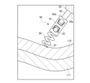
- FIG. 10 shows a mucous membrane 110 that is the inner wall of the hollow organ, a serosa 111 that is the outer wall, and a tumor 112 that has arisen on the inner wall side of the hollow organ. Note that, for clarity of illustration, the mucous membrane 110 and serosa 111 of the hollow organ are shown in cross section in FIGS. 10 to 15.
- the endoscope 100 is inserted into the body, and the distal end of the endoscope 100 is placed near the lesion (tumor 112) in the hollow organ where the medical marker 60 is placed.
- a medical marker 60 is attached to the engagement portion 50 on the distal end side of the shaft member 40 inserted through the sheath 30, and the outer tube 20, which accommodates the sheath 30 and the shaft member 40 in its inner cavity, is inserted into the channel of the endoscope 100.
- the sheath 30 and the distal end of the shaft member 40 are exposed from the distal end side of the outer tube 20 and placed near the tumor 112.
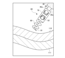
- FIGS. 11 to 15 are schematic enlarged views of the vicinity of region A in FIG. 10, and are diagrams showing the first to fifth steps of the treatment of indwelling the medical marker 60 in the hollow organ.
- the sheath 30, the engaging portion 50 formed at the distal end of the shaft member 40, and the medical marker 60 are exposed from the distal end of the outer tube 20.
- the most distal end 81 of the coil member 80 of the medical marker 60 is positioned so as to contact the inner wall of the hollow organ located near the tumor 112. Then, while pressing the most distal end 81 of the coil member 80 against the inner wall of the hollow organ, the rotation operation member 91b of the shaft member rotation mechanism 91 is displaced toward the proximal end side.
- the shaft member 40 rotates in the first direction, and the engagement portion 50 integrally formed at the distal end of the shaft member 40 rotates.
- the medical marker 60 connected to the engaging portion 50 rotates in the first direction, and the distalmost end 81 of the coil member 80 of the medical marker 60 pierces the inner wall of the hollow organ.
- the distal end 81 of the coil member 80 advances deep into the inner wall of the hollow organ, and as shown in FIG. Penetrate inside.
- the rotation operation member 91b of the shaft member rotation mechanism 91 is displaced to the distal end side to move the shaft member 40, the engaging portion 50, and the medical marker 60.
- the medical marker 60 can be removed from the inner wall of the hollow organ.
- the coil member 80 of the medical marker 60 may be repositioned to another position to penetrate the inner wall of the hollow organ.
- the distal end 30a of the sheath 30 advances toward the distal end with respect to the shaft member 40 and comes into contact with the proximal end 70a of the base member 70.
- the distal end 30a of the sheath 30 pushes the medical marker 60 toward the distal end, and the spherical member 52 of the engaging portion 50 comes out from the engaging portion receiving hole 71 of the medical marker 60.
- the medical marker 60 is removed from the engaging portion 50.
- the medical marker 60 is left in the body with the coil member 80 of the medical marker 60 penetrating the inner wall of the hollow organ.
- the outer tube 20 is taken out of the body together with the sheath 30 and the shaft member 40, and then a new A medical marker 60 is attached and the above-described steps are performed again. Thereby, as shown in FIG. 16, a plurality of new medical markers 60 can be attached to the inner wall of the hollow organ located near the tumor 112.
- the endoscope 100 is taken out of the body, and the procedure for placing the medical markers 60 is completed.
- the medical marker 60 indwelled in the body as described above at least a portion of the coil member 80 or the entire coil member 80 is made of a phosphor containing a fluorescent dye.
- the medical marker 60 is indwelled in the body with the coil member 80 penetrated into the body tissue that is the inner wall of the hollow organ. It is possible to visually check from For example, one or more medical markers 60 are placed near the lesion (tumor 112) as described above before a surgery in which a hollow organ is approached from outside, and excitation light is applied from outside the hollow organ during surgery.
- the position of the medical marker 60 can be specified by viewing the fluorescence emitted by the coil member 80 of the medical marker 60 using a camera or the like depending on the wavelength of the fluorescence. ) can be identified from outside the hollow organ.
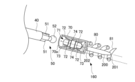
- FIG. 17 is a perspective view showing a state in which the medical marker 160 and the engaging portion 50 disposed at the distal end of the shaft member 40 are disconnected in the second embodiment of the present invention.
- 18 is a diagram schematically showing the inside of the medical marker 160 by drawing the medical marker 160 in cross section in the perspective view shown in FIG.
- a medical marker 160 according to the second embodiment has a fluorescent member 200 in the inner cavity formed by the coil member 80 in addition to the medical marker 60 according to the first embodiment. It has a set configuration.
- the fluorescent member 200 is, for example, a member that extends in the axial direction, and is arranged so that its extending direction coincides with the axial center line of the coil member 80.
- the distal end 201 of the fluorescent member 200 is disposed proximal to the most distal end 81 of the coil member 80 so as not to prevent the coil member 80 from penetrating the inner wall of the hollow organ. It is preferable that the fluorescent member 200 is housed inside.
- the other components of the medical marker 160 in the second embodiment are the same as those in the medical marker 60 in the first embodiment, and their explanation will be omitted.
- the fluorescent member 200 is made of a phosphor that at least partially contains a fluorescent dye. Only a portion of the fluorescent member 200 (for example, from the middle of the fluorescent member 200 to the distal end 201) may be composed of a fluorescent material containing a fluorescent dye. However, if the area of the phosphor's fluorescent screen (equal to the irradiation surface of the excitation light from the outside of the luminal organ) is increased, the visibility of the fluorescence of the phosphor from the outside of the luminal organ improves; Since the fluorescent member 200 can be manufactured easily, it is preferable that the entire fluorescent member 200 is made of a fluorescent material containing a fluorescent dye.
- the shape of the fluorescent member 200 is not particularly limited, the fluorescent member 200 may have a cylindrical shape, and the end surface of the distal end 201 may have a planar shape perpendicular to the axial direction.
- the distal end 201 of the fluorescent member 200 may be tapered toward the distal end, allowing it to pierce the inner wall of a hollow organ. It may be formed into a sharp shape.
- the fluorescent member 200 may be formed into a coil shape or a drill shape.
- the proximal end 202 of the fluorescent member 200 is fixed to the distal end of the base material 70.
- the fluorescent member 200 fixed to the base material 70 of the medical marker 160 also rotates.
- the fluorescent member 200 penetrates into the body tissue that is the inner wall of the hollow organ, the fluorescent member 200 also moves forward together with the coil member 80 and comes into contact with the inner wall of the hollow organ.
- the distalmost end 81 of the coil member 80 is flat, it advances while pressing the inner wall surface of the hollow organ.
- the distal end 201 of the fluorescent member 200 has a shape that becomes narrower toward the distal end side or has a sharper shape
- the distal end 201 of the fluorescent member 200 is shaped like the coil member 80.
- the fluorescent member 200 can be penetrated into the inner wall surface of the hollow organ by penetrating the inner wall surface of the hollow organ.
- the fluorescent member 200 and the base material 70 and coil member 80 of the medical marker 160 may be constructed using the same material or may be constructed using different materials.
- the fluorescent member 200, the base material 70, and the coil member 80 may be made of an integrated fluorescent substance.
- a cylindrical member made of metal or the like is processed by laser cutting or the like to form the base material 70 and the coil member 80, and then the proximal end 202 of the fluorescent member 200 partially or entirely made of fluorescent material. may be joined to the distal end of the base member 70.
- the medical marker 160 in the second embodiment can be placed in a hollow organ using a method similar to the procedure for placing the medical marker 160 in a hollow organ in the first embodiment described above.
- the fluorescent member 200 digs deep into the inner wall of the hollow organ, or Penetrate inside the inner wall of an organ. This makes it possible to visually recognize the fluorescence of the phosphor constituting the fluorescent member 200 from outside the hollow organ.
- the configuration of the medical marker 60 in the first embodiment and the configuration of the medical marker 160 in the second embodiment at least a portion of the coil member 80 or the entire coil member 80 is configured with a fluorescent material. Furthermore, a structure may be adopted in which the fluorescent member 200 is arranged inside the coil member 80.
- the medical markers 60 and 160 in the first and second embodiments are placed in a hollow organ in the body, and include a cylindrical base material 70 constituting a proximal end and a distal end.
- the coil member 80 is integrally formed with a coil member 80 formed so as to extend while being spirally wound around the axial direction.
- the coil member 80 constituting the distal end of the medical marker 60 in the first embodiment is at least partially or entirely made of a phosphor containing a fluorescent dye that emits fluorescence in a predetermined wavelength range when irradiated with excitation light. It is configured.
- a fluorescent member 200 At the distal end of the medical marker 160 in the second embodiment, there is a fluorescent member 200 at least partially or entirely made of a fluorescent substance containing a fluorescent dye that emits fluorescence in a predetermined wavelength range when irradiated with excitation light. is provided so as to extend in the axial direction in the inner cavity formed by the coil member 80.
- the fluorescent member 200 may be shaped such that its distal end 201 becomes thinner toward the distal end.
- the medical markers 60 and 160 in the first and second embodiments can penetrate inside the inner wall of a hollow organ while the coil member 80 rotates, and can be stably attached to the inner wall of a hollow organ. It is excellent and has an improved retention period.
- the positions of the medical markers 60 and 160 can be identified by visually recognizing the fluorescence emitted by the fluorescent substance, and the position of the medical markers 60 and 160 can be identified from outside the hollow organ. It has excellent visibility.
- the coil member 80 itself that penetrates inside the inner wall of the hollow organ is made of fluorescent material, when the medical marker 60 is attached to the inner wall of the hollow organ, It becomes possible to place the phosphor inside the inner wall of the hollow organ.
- the fluorescent member 200 made of fluorescent substance is placed near the inner wall of the hollow organ. It has excellent visibility from the outside of the hollow organ. Further, by providing the fluorescent member 200 as a separate member of the coil member 80, the coil member 80 can be made of metal or the like, for example, and the mounting stability of the medical marker 160 can be maintained. Furthermore, by shaping the distal end 201 of the fluorescent member 200 so that it becomes thinner toward the distal end, the fluorescent member 200 can penetrate inside the inner wall of the hollow organ, and from the outside of the hollow organ. visibility can be improved.
- the medical markers 60 and 160 in the first and second embodiments may be formed such that the distal end of the coil member 80 becomes thinner toward the distal end side. Thereby, the distal end of the coil member 80 pierces the inner wall of the hollow organ, thereby improving the ability to penetrate into the inner wall of the hollow organ.
- the base material 70 is removably connected to the distal end of the shaft member 40 capable of transmitting torque, and the base material 70 and the coil member 80 may be configured to rotate.
- the medical markers 60, 160 including the base material 70 and the coil member 80 are rotated, and the coil member 80 is made to penetrate inside the inner wall of the hollow organ. I can do it.
Landscapes
- Health & Medical Sciences (AREA)
- Surgery (AREA)
- Life Sciences & Earth Sciences (AREA)
- Heart & Thoracic Surgery (AREA)
- Pathology (AREA)
- Oral & Maxillofacial Surgery (AREA)
- Engineering & Computer Science (AREA)
- Biomedical Technology (AREA)
- Nuclear Medicine, Radiotherapy & Molecular Imaging (AREA)
- Medical Informatics (AREA)
- Molecular Biology (AREA)
- Animal Behavior & Ethology (AREA)
- General Health & Medical Sciences (AREA)
- Public Health (AREA)
- Veterinary Medicine (AREA)
- Media Introduction/Drainage Providing Device (AREA)
Priority Applications (2)
| Application Number | Priority Date | Filing Date | Title |
|---|---|---|---|
| JP2024512909A JPWO2023191058A1 (https=) | 2022-03-31 | 2023-03-31 | |
| CN202380019429.2A CN118632672A (zh) | 2022-03-31 | 2023-03-31 | 医疗用标记物 |
Applications Claiming Priority (2)
| Application Number | Priority Date | Filing Date | Title |
|---|---|---|---|
| JP2022-058746 | 2022-03-31 | ||
| JP2022058746 | 2022-03-31 |
Publications (1)
| Publication Number | Publication Date |
|---|---|
| WO2023191058A1 true WO2023191058A1 (ja) | 2023-10-05 |
Family
ID=88202473
Family Applications (1)
| Application Number | Title | Priority Date | Filing Date |
|---|---|---|---|
| PCT/JP2023/013568 Ceased WO2023191058A1 (ja) | 2022-03-31 | 2023-03-31 | 医療用マーカー |
Country Status (3)
| Country | Link |
|---|---|
| JP (1) | JPWO2023191058A1 (https=) |
| CN (1) | CN118632672A (https=) |
| WO (1) | WO2023191058A1 (https=) |
Citations (5)
| Publication number | Priority date | Publication date | Assignee | Title |
|---|---|---|---|---|
| JPH0852226A (ja) * | 1994-07-28 | 1996-02-27 | Medtronic Inc | 人体植え込み型の医療用電気リード |
| JP2008516739A (ja) * | 2004-10-20 | 2008-05-22 | ボストン サイエンティフィック リミテッド | リード無し心臓刺激システム |
| JP2009518115A (ja) * | 2005-12-09 | 2009-05-07 | ボストン サイエンティフィック サイムド,インコーポレイテッド | 心刺激システム |
| JP2021029361A (ja) * | 2019-08-19 | 2021-03-01 | 国立大学法人高知大学 | 開閉クリップ |
| JP2021517485A (ja) * | 2018-03-12 | 2021-07-26 | パイプライン メディカル テクノロジーズ, インコーポレイテッド | 僧帽弁腱索修復のための方法および装置 |
-
2023
- 2023-03-31 JP JP2024512909A patent/JPWO2023191058A1/ja active Pending
- 2023-03-31 CN CN202380019429.2A patent/CN118632672A/zh active Pending
- 2023-03-31 WO PCT/JP2023/013568 patent/WO2023191058A1/ja not_active Ceased
Patent Citations (5)
| Publication number | Priority date | Publication date | Assignee | Title |
|---|---|---|---|---|
| JPH0852226A (ja) * | 1994-07-28 | 1996-02-27 | Medtronic Inc | 人体植え込み型の医療用電気リード |
| JP2008516739A (ja) * | 2004-10-20 | 2008-05-22 | ボストン サイエンティフィック リミテッド | リード無し心臓刺激システム |
| JP2009518115A (ja) * | 2005-12-09 | 2009-05-07 | ボストン サイエンティフィック サイムド,インコーポレイテッド | 心刺激システム |
| JP2021517485A (ja) * | 2018-03-12 | 2021-07-26 | パイプライン メディカル テクノロジーズ, インコーポレイテッド | 僧帽弁腱索修復のための方法および装置 |
| JP2021029361A (ja) * | 2019-08-19 | 2021-03-01 | 国立大学法人高知大学 | 開閉クリップ |
Also Published As
| Publication number | Publication date |
|---|---|
| CN118632672A (zh) | 2024-09-10 |
| JPWO2023191058A1 (https=) | 2023-10-05 |
Similar Documents
| Publication | Publication Date | Title |
|---|---|---|
| JP7632511B2 (ja) | 生体内留置クリップ | |
| JP7632510B2 (ja) | 生体内留置クリップ | |
| JP7790415B2 (ja) | 医療用マーカー | |
| CA2590951C (en) | Flexible surgical needle device | |
| JP7671679B2 (ja) | 偏心性の結節組織を採取する為のシステム | |
| EP3890624A1 (en) | Endoscopic tissue approximation system and methods | |
| JP6161096B2 (ja) | 生体圧迫クリップ | |
| US20050288550A1 (en) | Lung access device | |
| JP7087582B2 (ja) | 生体内留置クリップ | |
| JPWO2015194280A1 (ja) | マーキングシステム | |
| WO2023191058A1 (ja) | 医療用マーカー | |
| US8849377B2 (en) | Intraluminal tissue markers | |
| JP7775769B2 (ja) | 医療用マーカー | |
| JP6211234B2 (ja) | 内視鏡用アタッチメント及び内視鏡システム | |
| WO2023191059A1 (ja) | 医療用マーカー | |
| JP2026049396A (ja) | 医療用マーカー | |
| JP7562090B1 (ja) | マーカー、マーカー留置具及びマーカー検出装置 | |
| WO2026053758A1 (ja) | 胆管チューブステント | |
| JP2025532900A (ja) | 医療処置のためのビーコンデバイス、システム、及び方法 | |
| JP2003164458A (ja) | 医療器具 |
Legal Events
| Date | Code | Title | Description |
|---|---|---|---|
| 121 | Ep: the epo has been informed by wipo that ep was designated in this application |
Ref document number: 23781066 Country of ref document: EP Kind code of ref document: A1 |
|
| WWE | Wipo information: entry into national phase |
Ref document number: 202380019429.2 Country of ref document: CN |
|
| ENP | Entry into the national phase |
Ref document number: 2024512909 Country of ref document: JP Kind code of ref document: A |
|
| NENP | Non-entry into the national phase |
Ref country code: DE |
|
| 122 | Ep: pct application non-entry in european phase |
Ref document number: 23781066 Country of ref document: EP Kind code of ref document: A1 |