WO2023189508A1 - 方向制御弁 - Google Patents
方向制御弁 Download PDFInfo
- Publication number
- WO2023189508A1 WO2023189508A1 PCT/JP2023/009720 JP2023009720W WO2023189508A1 WO 2023189508 A1 WO2023189508 A1 WO 2023189508A1 JP 2023009720 W JP2023009720 W JP 2023009720W WO 2023189508 A1 WO2023189508 A1 WO 2023189508A1
- Authority
- WO
- WIPO (PCT)
- Prior art keywords
- spool
- pair
- supply
- annular grooves
- control valve
- Prior art date
- Legal status (The legal status is an assumption and is not a legal conclusion. Google has not performed a legal analysis and makes no representation as to the accuracy of the status listed.)
- Ceased
Links
Images


Classifications
-
- F—MECHANICAL ENGINEERING; LIGHTING; HEATING; WEAPONS; BLASTING
- F15—FLUID-PRESSURE ACTUATORS; HYDRAULICS OR PNEUMATICS IN GENERAL
- F15B—SYSTEMS ACTING BY MEANS OF FLUIDS IN GENERAL; FLUID-PRESSURE ACTUATORS, e.g. SERVOMOTORS; DETAILS OF FLUID-PRESSURE SYSTEMS, NOT OTHERWISE PROVIDED FOR
- F15B11/00—Servomotor systems without provision for follow-up action ; Circuits therefor
- F15B11/02—Systems essentially incorporating special features for controlling the speed or the actuating force of an output member
- F15B11/04—Systems essentially incorporating special features for controlling the speed or the actuating force of an output member for controlling the speed
- F15B11/042—Systems essentially incorporating special features for controlling the speed or the actuating force of an output member for controlling the speed by means in the feed line
-
- F—MECHANICAL ENGINEERING; LIGHTING; HEATING; WEAPONS; BLASTING
- F15—FLUID-PRESSURE ACTUATORS; HYDRAULICS OR PNEUMATICS IN GENERAL
- F15B—SYSTEMS ACTING BY MEANS OF FLUIDS IN GENERAL; FLUID-PRESSURE ACTUATORS, e.g. SERVOMOTORS; DETAILS OF FLUID-PRESSURE SYSTEMS, NOT OTHERWISE PROVIDED FOR
- F15B11/00—Servomotor systems without provision for follow-up action ; Circuits therefor
- F15B11/02—Systems essentially incorporating special features for controlling the speed or the actuating force of an output member
- F15B11/04—Systems essentially incorporating special features for controlling the speed or the actuating force of an output member for controlling the speed
- F15B11/044—Systems essentially incorporating special features for controlling the speed or the actuating force of an output member for controlling the speed by means in the return line
-
- F—MECHANICAL ENGINEERING; LIGHTING; HEATING; WEAPONS; BLASTING
- F16—ENGINEERING ELEMENTS AND UNITS; GENERAL MEASURES FOR PRODUCING AND MAINTAINING EFFECTIVE FUNCTIONING OF MACHINES OR INSTALLATIONS; THERMAL INSULATION IN GENERAL
- F16K—VALVES; TAPS; COCKS; ACTUATING-FLOATS; DEVICES FOR VENTING OR AERATING
- F16K11/00—Multiple-way valves, e.g. mixing valves; Pipe fittings incorporating such valves
- F16K11/02—Multiple-way valves, e.g. mixing valves; Pipe fittings incorporating such valves with all movable sealing faces moving as one unit
- F16K11/06—Multiple-way valves, e.g. mixing valves; Pipe fittings incorporating such valves with all movable sealing faces moving as one unit comprising only sliding valves, i.e. sliding closure elements
- F16K11/065—Multiple-way valves, e.g. mixing valves; Pipe fittings incorporating such valves with all movable sealing faces moving as one unit comprising only sliding valves, i.e. sliding closure elements with linearly sliding closure members
- F16K11/07—Multiple-way valves, e.g. mixing valves; Pipe fittings incorporating such valves with all movable sealing faces moving as one unit comprising only sliding valves, i.e. sliding closure elements with linearly sliding closure members with cylindrical slides
-
- F—MECHANICAL ENGINEERING; LIGHTING; HEATING; WEAPONS; BLASTING
- F16—ENGINEERING ELEMENTS AND UNITS; GENERAL MEASURES FOR PRODUCING AND MAINTAINING EFFECTIVE FUNCTIONING OF MACHINES OR INSTALLATIONS; THERMAL INSULATION IN GENERAL
- F16K—VALVES; TAPS; COCKS; ACTUATING-FLOATS; DEVICES FOR VENTING OR AERATING
- F16K3/00—Gate valves or sliding valves, i.e. cut-off apparatus with closing members having a sliding movement along the seat for opening and closing
- F16K3/22—Gate valves or sliding valves, i.e. cut-off apparatus with closing members having a sliding movement along the seat for opening and closing with sealing faces shaped as surfaces of solids of revolution
- F16K3/24—Gate valves or sliding valves, i.e. cut-off apparatus with closing members having a sliding movement along the seat for opening and closing with sealing faces shaped as surfaces of solids of revolution with cylindrical valve members
Definitions
- the present disclosure relates to a directional control valve provided in a hydraulic circuit.
- the directional control valve includes a housing including a spool hole and a spool inserted into the spool hole.
- multiple directional control valves may be connected to the pump in parallel.
- a hydraulic circuit corresponding to that hydraulic actuator is used.
- a priority valve which is a variable throttle, is sometimes provided upstream of the directional control valve (see, for example, Patent Document 1).
- an object of the present disclosure is to provide a directional control valve that can limit the amount of hydraulic fluid supplied to a specific hydraulic actuator without using a priority valve.
- the present disclosure includes a housing including a spool hole, a pump channel, a tank channel, and a pair of supply/discharge channels; a spool that is cut off from the tank flow path and communicates one of the pair of supply/discharge flow paths with the pump flow path and communicates the other with the tank flow path when moved from the neutral position;
- the opening area between one of the supply/discharge channels and the pump channel increases to a maximum value while the stroke of the spool increases to a predetermined value, and when the stroke of the spool exceeds the predetermined value.
- a directional control valve that is smaller than the maximum value.
- a directional control valve that can limit the amount of hydraulic fluid supplied to a specific hydraulic actuator without using a priority valve.
- FIG. 1 is a diagram showing a hydraulic circuit including a directional control valve according to an embodiment.
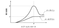
- FIG. It is a graph which shows the relationship between the spool stroke and opening area in the said directional control valve.
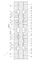
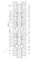
- FIG. 3 is a cross-sectional view of a portion of the directional control valve, showing a state in which the spool is in a neutral position. It is a sectional view of a part of the direction control valve, and shows a state where the spool stroke is a predetermined value.
- FIG. 3 is a cross-sectional view of a portion of the directional control valve, showing a state where the spool stroke is at its maximum.
- FIG. 1 shows a hydraulic circuit including a directional control valve 1 according to an embodiment.
- the hydraulic circuit also includes another directional control valve 93.
- the direction control valve 1 is for switching the operating direction of a hydraulic actuator 92 that operates in both directions
- the directional control valve 93 is for switching the operating direction of a hydraulic actuator 96 that operates in both directions.
- hydraulic actuators 92, 96 are double acting cylinders, hydraulic motors, and the like.
- the directional control valve 1 includes a housing 2 including a spool hole 20 (see FIG. 3), and a spool 6 inserted into the spool hole 20.
- directional control valve 93 includes a housing 94 including a spool hole, and a spool 95 inserted into the spool hole.
- the housings 2, 94 of both directional control valves 1, 93 may be integrated.
- the directional control valve 1 is connected to the pump 91 in parallel with the directional control valve 93 via a supply line 15, and is connected to a tank in parallel with the directional control valve 93 via a tank line 16. Further, the directional control valve 1 is connected to a hydraulic actuator 92 through a pair of supply/discharge lines 17 .
- the housing 2 includes a pump channel 3, a tank channel 4, and a pair of supply/discharge channels 5A and 5B.
- the pump channel 3 forms a pump port 11 on the surface of the housing 2, to which a supply line 15 is connected.
- the tank flow path 4 forms a tank port 12 on the surface of the housing 2, and a tank line 16 is connected to the tank port 12.
- the supply/discharge channels 5A, 5B form supply/discharge ports 13 on the surface of the housing 2, and supply/discharge lines 17 are connected to these supply/discharge ports 13, respectively.
- the pump flow path 3 and the tank flow path 4 are connected within the housings 2 and 94 instead of the supply line 15 and the tank line 16 being branched.
- the directional control valves 1 and 93 may be connected to the pump 91 in parallel.
- the spool 6 blocks the supply/discharge channels 5A, 5B from the pump channel 3 and the tank channel 4 at the neutral position, and when moved from the neutral position to one side and the other, pumps one of the supply/discharge channels 5A, 5B.
- the other end is connected to the flow path 3 and the other end is connected to the tank flow path 4.
- the opening area of the meterine between one of the supply/discharge channels 5A and 5B and the pump channel 3 is at its maximum while the stroke of the spool 6 increases to a predetermined value ⁇ . It increases to a value ⁇ , and becomes smaller than the maximum value ⁇ when the stroke of the spool 6 exceeds a predetermined value ⁇ .
- the percentage of the opening area of the meterine at the full stroke of the spool 6 with respect to the maximum value ⁇ depends on the ratio of the hydraulic actuator 96 to the hydraulic actuator 92 when the hydraulic actuators 92 and 96 are operated simultaneously. It can be determined as appropriate depending on the priority.
- the meter-out opening area between the other of the supply/discharge channels 5A, 5B and the tank channel 4 increases to the maximum value ⁇ while the stroke of the spool 6 increases to the predetermined value ⁇ .
- the stroke of the spool 6 exceeds a predetermined value ⁇ , it is maintained at the maximum value ⁇ .
- a central annular groove 21 is formed in the center of the spool hole 20 in the housing 2, and the central annular groove 21 is recessed radially outward from the spool hole 20.
- a pair of inflow annular grooves 22 and 23 are formed on both sides of the spool hole 20 and are recessed radially outward from the spool hole 20.
- the pump channel 3 includes a main channel forming the pump port 11 and a plurality of branch channels 31 branching from the main channel, and the branch channels 31 are connected to the inflow annular grooves 22 and 23, respectively.
- the housing 2 is formed with a pair of intermediate annular grooves 24 and 25 that are recessed radially outward from the spool hole 20 on the outside of the inflow annular groove 22, and on the outside of the intermediate annular grooves 24 and 25.
- a pair of outflow annular grooves 26 and 27 are formed that are depressed radially outward from the spool hole 20.
- the supply/discharge channels 5A and 5B are connected to intermediate annular grooves 24 and 25, respectively.
- the tank channel 4 includes a main channel forming the tank port 12 and a plurality of branch channels 41 branching from the main channel, and the branch channels 41 are connected to the outflow annular grooves 26 and 27, respectively.
- the spool 6 has a central land portion 61 located between the inflow annular grooves 22 and 23 when the spool 6 is located at the neutral position, and a pair of supply/discharge land portions located on both sides of the central land portion 61. 64, 65, and a pair of end lands 68, 69 located outside the supply/discharge lands 64, 65.
- the spool 6 also includes a pair of inner small diameter portions 62 and 63 that connect the central land portion 61 and the supply and discharge lands 64 and 65, respectively, and a pair of inner small diameter portions 62 and 63 that connect the supply and discharge lands 64 and 65 and the terminal land portions 68 and 69, respectively. It includes a pair of outer small diameter portions 66 and 67 that are connected.
- annular groove 61C is formed in the center of the central land portion 61, and the central land portion 61 is divided into a first central land portion 61A and a second central land portion 61B.
- the annular groove 61C may not be formed in the central land portion 61, and the central land portion 61 may be continuous from one end to the other end.
- the supply/discharge lands 64 and 65 close the intermediate annular grooves 24 and 25, respectively, when the spool 6 is located at the neutral position.
- Annular flow paths 81 and 82 are formed between the inner small diameter portions 62 and 63 and the inner circumferential surface of the spool hole 20, respectively, and annular flow paths 81 and 82 are formed between the outer small diameter portions 66 and 67 and the inner circumferential surface of the spool hole 20.
- Annular channels 83 and 84 are formed in each of the channels.
- a plurality of notches 71 that open toward the annular flow path 81 are formed on the circumferential surface of the first central land portion 61A, and a plurality of notches 71 that open toward the annular flow path 81 are formed on the circumferential surface of the second central land portion 61B.
- a plurality of open notches 72 are formed.
- a plurality of notches 73 that open toward the annular flow path 81 are formed at the inner end of the circumferential surface of the supply/discharge land portion 64, and a plurality of notches 73 that open toward the annular flow path 83 are formed at the outer end.
- a notch 75 is formed.
- the annular flow path 83 always overlaps the outflow annular groove 26 regardless of the position of the spool 6.
- a plurality of notches 74 are formed at the inner end of the peripheral surface of the supply/discharge land portion 65 and open toward the annular flow path 82 , and at the outer end, a plurality of notches 74 are formed toward the annular flow path 84 .
- a plurality of open notches 76 are formed.
- the annular flow path 84 always overlaps the outflow annular groove 27 regardless of the position of the spool 6.
- the maximum value ⁇ of the opening area of the meterine is the total cross-sectional area of the notch 73 on a plane perpendicular to the axial direction of the spool 6.
- the first central land portion 61A is positioned to cover the inflow annular groove 22.
- the inflow annular groove 22 directly communicates with the annular flow path 81, but at a position where the first central land portion 61A covers the inflow annular groove 22.
- the inflow annular groove 22 communicates with the annular flow path 81 through the notch 71 .
- the opening area of the meterine is reduced from the maximum value ⁇ to the total cross-sectional area of the notch 71 on the plane orthogonal to the axial direction of the spool 6.
- the maximum value ⁇ of the meter-out opening area is the total cross-sectional area of the notch 76 on the plane perpendicular to the axial direction of the spool 6, and the stroke of the spool 6 is increased from the predetermined value ⁇ or a smaller value to the maximum value. The maximum value ⁇ is maintained until .
- the stroke of the spool 6 of the directional control valve 1 is set to be less than the predetermined value ⁇ . If it is made larger, the amount of hydraulic fluid supplied to the hydraulic actuator 92 can be restricted. Moreover, in this embodiment, when limiting the amount of hydraulic fluid supplied to the hydraulic actuator 92, the meter-out opening area can be maintained at the maximum value ⁇ . In other words, the amount of hydraulic fluid supplied to the hydraulic actuator 92 can be restricted without reducing the meter-out opening area.
- the direction control valve 1 is a swing direction control valve for a swing motor
- the direction control valve 93 is a boom direction control valve for a boom cylinder. It may be.
- the spool stroke of the directional control valve 1 is made larger than the predetermined value ⁇ when a combined operation of a swing operation and a boom raising operation is performed, the supply of hydraulic fluid to the boom cylinder is more efficient than the supply of hydraulic fluid to the swing motor.
- the boom raising speed can be secured by giving priority to the supply of hydraulic fluid.
- the meter-out opening area of the directional control valve 1 may become smaller than the maximum value ⁇ when the stroke of the spool 6 exceeds the predetermined value ⁇ .
- the present disclosure includes a housing including a spool hole, a pump channel, a tank channel, and a pair of supply/discharge channels; a spool that is cut off from the tank flow path and communicates one of the pair of supply/discharge flow paths with the pump flow path and communicates the other with the tank flow path when moved from the neutral position;
- the opening area between one of the supply/discharge channels and the pump channel increases to a maximum value while the stroke of the spool increases to a predetermined value, and when the stroke of the spool exceeds the predetermined value.
- a directional control valve that is smaller than the maximum value.
- the above-mentioned direction control valve can be The amount of hydraulic fluid supplied to a particular hydraulic actuator corresponding to a control valve can be limited.
- the opening area between the other of the pair of supply/discharge flow paths and the tank flow path increases to a maximum value while the stroke of the spool increases to the predetermined value, and when the stroke of the spool increases to the predetermined value. If the maximum value is exceeded, the maximum value may be maintained. According to this configuration, when restricting the amount of hydraulic fluid supplied to a specific hydraulic actuator, the meter-out opening area can be maintained at the maximum value.
- the housing includes a pair of inflow annular grooves recessed radially outward from the spool hole, and a pair of intermediate annular grooves recessed radially outward from the spool hole outside the pair of inflow annular grooves.
- the supply/discharge channels are connected to the pair of intermediate annular grooves, the tank channel is connected to the pair of outflow annular grooves, and the spool is connected to the pair of intermediate annular grooves when the spool is in the neutral position.
- a central land located between the inflow annular grooves; a pair of supply/discharge lands that respectively close the pair of intermediate annular grooves when the spool is located at the neutral position; A pair of small diameter portions each connecting a pair of supply/discharge land portions, and a space between each of the pair of small diameter portions and an inner circumferential surface of the spool hole when the spool moves from the neutral position.
- An annular flow path communicating with the corresponding intermediate annular groove is formed, and when the stroke of the spool exceeds the predetermined value, the central land portion is positioned to cover one of the pair of inflow annular grooves.
- the inflow annular groove may communicate with the annular flow path through a notch formed on the circumferential surface of the central land.
Landscapes
- Engineering & Computer Science (AREA)
- General Engineering & Computer Science (AREA)
- Mechanical Engineering (AREA)
- Physics & Mathematics (AREA)
- Fluid Mechanics (AREA)
- Multiple-Way Valves (AREA)
- Sliding Valves (AREA)
Abstract
Description
本開示は上述した実施形態に限定されるものではなく、本開示の要旨を逸脱しない範囲で種々の変形が可能である。
本開示は、スプール穴、ポンプ流路、タンク流路および一対の給排流路を含むハウジングと、前記スプール穴に挿入され、中立位置では前記一対の給排流路を前記ポンプ流路および前記タンク流路から遮断し、前記中立位置から移動したときに前記一対の給排流路の一方を前記ポンプ流路と連通させるとともに他方を前記タンク流路と連通させるスプールと、を備え、前記一対の給排流路の一方と前記ポンプ流路との間の開口面積は、前記スプールのストロークが所定値まで増加する間は最大値まで増加し、前記スプールのストロークが前記所定値を超えるときは前記最大値よりも小さくなる、方向制御弁を提供する。
2 ハウジング
20 スプール穴
22,23 流入用環状溝
24,25 中間環状溝
26,27 流出用環状溝
3 ポンプ流路
4 タンク流路
5A,5B 給排流路
6 スプール
61 中央ランド部
62,63 内側小径部
64,65 給排ランド部
66,67 外側小径部
68,69 末端ランド部
71~76 ノッチ
81~84 環状流路
Claims (3)
- スプール穴、ポンプ流路、タンク流路および一対の給排流路を含むハウジングと、
前記スプール穴に挿入され、中立位置では前記一対の給排流路を前記ポンプ流路および前記タンク流路から遮断し、前記中立位置から移動したときに前記一対の給排流路の一方を前記ポンプ流路と連通させるとともに他方を前記タンク流路と連通させるスプールと、を備え、
前記一対の給排流路の一方と前記ポンプ流路との間の開口面積は、前記スプールのストロークが所定値まで増加する間は最大値まで増加し、前記スプールのストロークが前記所定値を超えるときは前記最大値よりも小さくなる、方向制御弁。 - 前記一対の給排流路の他方と前記タンク流路との間の開口面積は、前記スプールのストロークが前記所定値まで増加する間は最大値まで増加し、前記スプールのストロークが前記所定値を超えるときは前記最大値に維持される、請求項1に記載の方向制御弁。
- 前記ハウジングは、前記スプール穴から径方向外向きに窪む一対の流入用環状溝と、前記一対の流入用環状溝の外側で前記スプール穴から径方向外向きに窪む一対の中間環状溝と、前記一対の中間環状溝の外側で前記スプール穴から径方向外向きに窪む一対の流出用環状溝を含み、
前記ポンプ流路は前記一対の流入用環状溝と接続され、前記一対の給排流路は前記一対の中間環状溝とそれぞれ接続され、前記タンク流路は前記一対の流出用環状溝と接続され、
前記スプールは、当該スプールが前記中立位置に位置するときに前記一対の流入用環状溝の間に位置する中央ランド部と、当該スプールが前記中立位置に位置するときに前記一対の中間環状溝をそれぞれ閉塞する一対の給排ランド部と、前記中央ランド部と前記一対の給排ランド部とをそれぞれ連結する一対の小径部を含み、
前記一対の小径部のそれぞれと前記スプール穴の内周面との間には、前記スプールが前記中立位置から移動したときに対応する前記中間環状溝と連通する環状流路が形成されており、
前記スプールのストロークが前記所定値を超えるとき、前記中央ランド部が前記一対の流入用環状溝の一方を覆う位置に位置し、当該中央ランド部の周面に形成されたノッチを通じて前記流入用環状溝が前記環状流路と連通する、請求項1または2に記載の方向制御弁。
Priority Applications (1)
| Application Number | Priority Date | Filing Date | Title |
|---|---|---|---|
| CN202380019656.5A CN118591704A (zh) | 2022-03-28 | 2023-03-13 | 方向控制阀 |
Applications Claiming Priority (2)
| Application Number | Priority Date | Filing Date | Title |
|---|---|---|---|
| JP2022-051498 | 2022-03-28 | ||
| JP2022051498A JP7798647B2 (ja) | 2022-03-28 | 2022-03-28 | 方向制御弁 |
Publications (1)
| Publication Number | Publication Date |
|---|---|
| WO2023189508A1 true WO2023189508A1 (ja) | 2023-10-05 |
Family
ID=88200937
Family Applications (1)
| Application Number | Title | Priority Date | Filing Date |
|---|---|---|---|
| PCT/JP2023/009720 Ceased WO2023189508A1 (ja) | 2022-03-28 | 2023-03-13 | 方向制御弁 |
Country Status (3)
| Country | Link |
|---|---|
| JP (1) | JP7798647B2 (ja) |
| CN (1) | CN118591704A (ja) |
| WO (1) | WO2023189508A1 (ja) |
Citations (2)
| Publication number | Priority date | Publication date | Assignee | Title |
|---|---|---|---|---|
| WO2014170977A1 (ja) * | 2013-04-17 | 2014-10-23 | トヨタ自動車株式会社 | 油圧制御バルブおよび油圧制御装置 |
| JP2018017334A (ja) * | 2016-07-28 | 2018-02-01 | 住友精密工業株式会社 | 流量制御弁 |
Family Cites Families (2)
| Publication number | Priority date | Publication date | Assignee | Title |
|---|---|---|---|---|
| JPH11280705A (ja) * | 1998-03-27 | 1999-10-15 | Shin Caterpillar Mitsubishi Ltd | 油圧弁操作装置 |
| JP6490507B2 (ja) * | 2015-06-16 | 2019-03-27 | 日立建機株式会社 | スプール弁装置 |
-
2022
- 2022-03-28 JP JP2022051498A patent/JP7798647B2/ja active Active
-
2023
- 2023-03-13 WO PCT/JP2023/009720 patent/WO2023189508A1/ja not_active Ceased
- 2023-03-13 CN CN202380019656.5A patent/CN118591704A/zh active Pending
Patent Citations (2)
| Publication number | Priority date | Publication date | Assignee | Title |
|---|---|---|---|---|
| WO2014170977A1 (ja) * | 2013-04-17 | 2014-10-23 | トヨタ自動車株式会社 | 油圧制御バルブおよび油圧制御装置 |
| JP2018017334A (ja) * | 2016-07-28 | 2018-02-01 | 住友精密工業株式会社 | 流量制御弁 |
Also Published As
| Publication number | Publication date |
|---|---|
| JP2023144499A (ja) | 2023-10-11 |
| JP7798647B2 (ja) | 2026-01-14 |
| CN118591704A (zh) | 2024-09-03 |
Similar Documents
| Publication | Publication Date | Title |
|---|---|---|
| KR102678535B1 (ko) | 방향 전환 밸브 및 유압 시스템 | |
| JP6647826B2 (ja) | 方向切換弁及び油圧システム | |
| US10969026B2 (en) | Valve device | |
| KR102773376B1 (ko) | 방향 전환 밸브 및 유압 시스템 | |
| JP2014181802A (ja) | 緩衝弁 | |
| CN103225633A (zh) | 液压换向阀、液压换向阀组和工程机械 | |
| CN113544390B (zh) | 流量控制阀 | |
| GB2554244A (en) | Flow control valve | |
| US20190072115A1 (en) | Fluid pressure control device | |
| US11137081B2 (en) | Control valve | |
| JP6552829B2 (ja) | 方向切換弁 | |
| JP2023144499A (ja) | 方向制御弁 | |
| JP6898834B2 (ja) | 流体圧制御装置 | |
| JP7397561B2 (ja) | 弁装置 | |
| JP7723588B2 (ja) | 弁装置 | |
| KR20200109242A (ko) | 제어 밸브 및 건설 기계용 유압 시스템 | |
| US11460053B2 (en) | Open center control valve configured to combine fluid flow received from multiple sources | |
| JPS6139551B2 (ja) | ||
| JP2022091424A (ja) | スプール、及びスプール弁 | |
| JP2002206505A (ja) | 旋回用油圧回路 | |
| JP2001159470A (ja) | スプール形切換弁 | |
| JP3375670B2 (ja) | コントロールバルブ |
Legal Events
| Date | Code | Title | Description |
|---|---|---|---|
| 121 | Ep: the epo has been informed by wipo that ep was designated in this application |
Ref document number: 23779528 Country of ref document: EP Kind code of ref document: A1 |
|
| WWE | Wipo information: entry into national phase |
Ref document number: 202380019656.5 Country of ref document: CN |
|
| WWE | Wipo information: entry into national phase |
Ref document number: 18846870 Country of ref document: US |
|
| NENP | Non-entry into the national phase |
Ref country code: DE |
|
| 122 | Ep: pct application non-entry in european phase |
Ref document number: 23779528 Country of ref document: EP Kind code of ref document: A1 |