WO2023189372A1 - 血圧測定装置 - Google Patents
血圧測定装置 Download PDFInfo
- Publication number
- WO2023189372A1 WO2023189372A1 PCT/JP2023/009119 JP2023009119W WO2023189372A1 WO 2023189372 A1 WO2023189372 A1 WO 2023189372A1 JP 2023009119 W JP2023009119 W JP 2023009119W WO 2023189372 A1 WO2023189372 A1 WO 2023189372A1
- Authority
- WO
- WIPO (PCT)
- Prior art keywords
- band
- blood pressure
- opposing
- measuring device
- pressure measuring
- Prior art date
- Legal status (The legal status is an assumption and is not a legal conclusion. Google has not performed a legal analysis and makes no representation as to the accuracy of the status listed.)
- Ceased
Links
Images


Classifications
-
- A—HUMAN NECESSITIES
- A61—MEDICAL OR VETERINARY SCIENCE; HYGIENE
- A61B—DIAGNOSIS; SURGERY; IDENTIFICATION
- A61B5/00—Measuring for diagnostic purposes; Identification of persons
- A61B5/02—Detecting, measuring or recording for evaluating the cardiovascular system, e.g. pulse, heart rate, blood pressure or blood flow
- A61B5/021—Measuring pressure in heart or blood vessels
- A61B5/022—Measuring pressure in heart or blood vessels by applying pressure to close blood vessels, e.g. against the skin; Ophthalmodynamometers
Definitions
- the present invention relates to a blood pressure measuring device that is attached to a living body to measure blood pressure.
- a blood pressure measuring device measures blood pressure by, for example, inflating and deflating a cuff wrapped around a living person's upper arm or wrist, and detecting the pressure of the cuff with a pressure sensor, thereby detecting vibrations of an artery wall.
- a so-called integrated type is known in which a cuff and a device body that supplies fluid to the cuff are integrated.
- a technology for attaching an integrated blood pressure measuring device to a living body such as a wrist
- a technology for attaching an integrated blood pressure measuring device to a living body such as a wrist
- a technology for attaching an integrated blood pressure measuring device to a living body such as a wrist
- a technology for attaching an integrated blood pressure measuring device to a living body such as a wrist a technology has been published in Japan that involves tightening and fixing a band provided on the device body to a living body with the cuff placed inside the band. It is disclosed in 2018-102868.
- the above-mentioned blood pressure measuring device equipped with a band whose length along the circumferential direction of the living body can be adjusted steplessly has the following problems.
- tensile forces in opposite directions in the circumferential direction of the living body act on one side of the body side where the band is laminated and the other side opposite to the body side.
- the hook-and-loop fastener generates part of the force that resists the tensile force generated in the region where the bands are laminated.
- the magnets In a blood pressure measuring device that uses magnets to fix the parts where the bands are stacked, the magnets generate some of this resisting force, but as wearable devices become smaller, the magnets become smaller. There is a possibility that this resisting force may become smaller.
- an object of the present invention is to provide a blood pressure measuring device that can measure blood pressure with high accuracy.
- the blood pressure measuring device includes a device main body, a cuff that is disposed in a region where an artery of a living body exists and is inflated by fluid, and a shaft portion that is orthogonal to a circumferential direction of the living body and that runs along an outer circumferential surface of the living body.
- a band body that is provided on the device body and has a band shape that is wrapped around the living body and that is folded back around the shaft portion and presses the cuff disposed inside against the living body; , a band having a fixing part that fixes the part to be stacked by being folded back at the shaft part of the band body by adsorption force, and a friction force that prevents the part to be stacked from moving in the circumferential direction between the band body and the band body.
- a blood pressure measuring device is provided, including a resistance section that causes a resistance to occur.
- the cuff is inflated by supply of fluid, and includes a bag-like structure such as an air bag.
- the length of the band attached to the living body along the circumferential direction of the living body can be adjusted steplessly.
- the frictional force generated between the resistance portion and the band can restrict movement of the region where the bands are stacked along the circumferential direction of the living body.
- loosening of the band means that the part where the band is laminated moves relative to the body when the band is tightened to the living body.
- the length of the band along the circumferential direction of the living body becomes longer. Since loosening of the band can be restricted, a decrease in the pressing force that presses the cuff against the artery can be prevented. As a result, it is possible to provide a blood pressure measuring device that can accurately measure blood pressure.
- a blood pressure measuring device that can steplessly adjust the length of the band along the circumferential direction of the living body when worn, and can measure blood pressure with high accuracy.
- the resistance part has an annular shape in which the laminated parts are arranged inside, and is a ring member that presses the laminated parts arranged inside in a direction toward each other.
- a measuring device is provided.
- a blood pressure measuring device including a magnet provided on the band main body, and the ring member includes a fixed portion fixed to the band main body by the magnet.
- the ring part can be fixed to the band when the blood pressure measuring device is removed from the living body, so it is possible to prevent the ring member from being lost.
- a blood pressure measuring device in which the resistance portion is provided on an outer peripheral portion of the shaft portion.
- the resistance portion includes a cylindrical portion in which the shaft portion is disposed, and a band portion that is integrally formed with the cylindrical portion and held between the laminated portions.
- a blood pressure measuring device is provided.
- the resistance portion is provided on the other side of at least one of the laminated portions.
- the frictional force between the laminated parts of the band body can be utilized.
- the present invention can provide a blood pressure measuring device that can steplessly adjust the length of the band along the circumferential direction of the living body when worn, and can measure blood pressure with high accuracy.
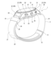
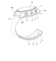
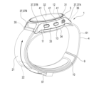
- FIG. 1 is a perspective view showing the configuration of a blood pressure measuring device according to an embodiment of the present invention.
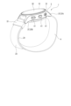
- FIG. 2 is an explanatory diagram showing the configuration of the blood pressure measuring device in a state where it is attached to the wrist.
- FIG. 3 is a perspective view showing the configuration of a main body of the blood pressure measuring device and a band used in the blood pressure measuring device.
- FIG. 4 is a perspective view showing the configuration of the main body of the device and the band.
- FIG. 5 is a plan view showing the configuration of the main body of the device and the band.
- FIG. 6 is a perspective view showing the configuration of the main body of the device, a curler used in the blood pressure measuring device, and a cuff structure used in the blood pressure measuring device.
- FIG. 1 is a perspective view showing the configuration of a blood pressure measuring device according to an embodiment of the present invention.
- FIG. 2 is an explanatory diagram showing the configuration of the blood pressure measuring device in a state where it is attached to the wrist.
- FIG. 7 is a plan view showing the configuration of the cuff structure.
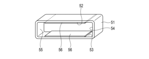
- FIG. 8 is a perspective view showing the configuration of a fixing member used in the same blood pressure measuring device.
- FIG. 9 is a perspective view showing the structure of the apparatus main body and the anti-slip sheet used in the blood pressure measuring apparatus.
- FIG. 10 is an explanatory diagram showing an example of how the blood pressure measuring device is worn.
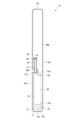
- FIG. 11 is an explanatory diagram showing the configuration of main parts of the blood pressure measuring device when measuring blood pressure.
- FIG. 12 is a perspective view showing the configuration of a resistance section according to a modified example.
- FIG. 13 is a perspective view showing the configuration of a ring member according to a modification.
- FIG. 14 is an explanatory diagram showing a blood pressure measuring device according to a modified example in a state attached to a wrist.
- FIG. 1 is a perspective view showing the configuration of a blood pressure measuring device 1.
- FIG. 2 is an explanatory diagram showing the configuration of the blood pressure measuring device 1 in a state where it is attached to a wrist 200.
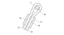
- FIG. 3 is a perspective view showing the configuration of the device body 3 used in the blood pressure measurement device 1 and the band 4 used in the blood pressure measurement device 1.
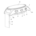
- FIG. 4 is a perspective view showing the configuration of the device main body 3 and the band 4.
- FIG. 4 shows a state in which the other end of the band 4 is detached from the device main body 3.
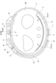
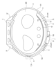
- FIG. 5 is a plan view showing the configuration of the device main body 3 and the band 4 as viewed from the wrist 200 side.
- FIG. 6 is a perspective view showing the configuration of the device main body 3, the curler 9, and the cuff structure 10.
- FIG. 7 is a plan view showing the configuration of the cuff structure 10.
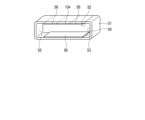
- FIG. 8 is a perspective view showing the configuration of the ring member 51.
- FIG. 9 is a perspective view showing the configuration of the device main body 3 and the anti-slip sheet 61.
- FIG. 10 is an explanatory diagram showing an example of how the blood pressure measuring device 1 is worn.
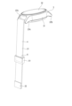
- FIG. 11 is an explanatory diagram showing the configuration of main parts of the blood pressure measuring device 1 when measuring blood pressure. Specifically, FIG. 11 shows the vicinity of the spring rod 35 cut away.
- the blood pressure measurement device 1 is an electronic blood pressure measurement device that is attached to a living body.
- the present embodiment will be described using, as an example, an electronic blood pressure measuring device in the form of a wearable device worn on the wrist 200.
- the blood pressure measuring device 1 includes a device main body 3, a band 4 for fixing the device main body 3 to a wrist 200, a magnet 6, a resistor 7, a band 4 and a wrist. 200, and a cuff structure 10 having a pressing cuff 71 and a sensing cuff 73.
- the device main body 3 includes, for example, a case 11, a display section 12, and an operation section 13.
- the device main body 3 also includes a pump 14 for inflating the cuff structure 10, a flow path section for fluidly connecting the pump 14 and the cuff structure 10, and a control board within the case 11.
- the case 11 includes an outer case 31 and a windshield 32 that covers an opening of the outer case 31 on the side opposite to the wrist 200 side.
- the outer case 31 includes, for example, a case body 33 formed in a cylindrical shape, a bottom wall portion 34 provided at one end of the case body 33, and two spring bars 35.
- the case body 33 is formed, for example, in a cylindrical shape.
- the case body 33 is provided with a pair of lugs 37 at symmetrical positions in the circumferential direction on the outer peripheral surface.
- the pair of lugs 37 are configured to protrude outward from the outer peripheral surface.
- one pair of lugs 37 is referred to as a first lug 37A
- the other pair of lugs 37 is referred to as a second lug 37B.
- One spring bar 35 is detachably attached between the pair of first lugs 37A. One end of the band 4 is attached to the spring bar 35 . The other spring bar 35 is provided between the pair of second lugs 37B. The other spring bar 35 is an example of a shaft portion that folds back the band body 21.
- the bottom wall portion 34 is provided at the opening of the case body 33 on the wrist 200 side and covers the opening.
- the wrist 200 side refers to the wrist 200 side when the blood pressure measuring device 1 is attached to the wrist 200.
- a connected portion 38 is formed on the bottom wall portion 34.
- Connected portion 38 is in fluid communication with pump 14 .
- a flow path that is continuous with the pump 14 is formed in the case 11, and the connected portion 38 constitutes a part of this flow path.
- the connected portion 38 is configured to be connectable to connecting portions 84 and 93, which will be described later, of the cuff structure 10.
- the cuff structure 10 includes, for example, two connecting parts 84 and 93, so two connected parts 38 are formed.
- One of the connected parts 38 is referred to as a first connected part 38A, and the other connected part 38 is referred to as a second connected part 38B.
- the windshield 32 is, for example, a circular glass plate.
- the display section 12 is arranged at a position facing the windshield 32. As shown in FIG. 1, the display section 12 is electrically connected to the control board.
- the display unit 12 is, for example, a liquid crystal display or an organic electroluminescent display.
- the display unit 12 displays various information including date and time, blood pressure values such as systolic blood pressure and diastolic blood pressure, and measurement results such as heart rate.
- the operation unit 13 is configured to be able to input instructions from the user.
- the operation unit 13 includes a plurality of buttons 41 provided on the case 11 and a sensor that detects the operation of the buttons 41.
- the buttons 41 For example, three buttons 41 are provided.
- the band 4 includes a band main body 21 and a fixing part 22.
- the band main body 21 is configured in the shape of a long band in one direction, which allows the device main body 3 to be fixed to the wrist 200.
- the band 4 is not stretchable and has flexibility.
- the band main body 21 is, for example, a metallic mesh band.
- One end of the band body 21 is fixed to a spring bar 35 provided between the pair of first lugs 37A so as to be rotatable around the spring bar 35.
- one end of the band 4 is provided with a hole in which a spring rod 35 is rotatably arranged.
- the band main body 21 has a portion where the other end side is folded back by the other spring bar 35 to be stacked.
- the part on the opposite side to the wrist 200 is defined as the first opposing part 23, and the part on the wrist 200 side is defined as the second opposing part 24.
- the distance between the surface of the second opposing portion 24 on the wrist 200 side and the surface of the first opposing portion 23 on the opposite side to the second opposing portion 24 side is the distance between the first opposing portion 23 and the second opposing portion 24 side.
- the end side where the opposing portion 24 is continuous, that is, the spring bar 35 side is farther apart than the other end side.
- the band body 21 is a metallic mesh band
- the first opposing part 23 and the second opposing part 24 are spaced apart from each other in the vicinity of the spring bar 35 due to the rigidity of the band 4. .
- the fixing part 22 is provided, for example, at the end of the band body 21.
- the fixing part 22 fixes the first opposing part 23 and the second opposing part 24 by adsorption force in a state where the band main body 21 is folded back by the spring bar 35.
- the fixing portion 22 prevents the first opposing portion 23 and the second opposing portion 24 from moving away from each other in the stacking direction due to the adsorption force.
- the fixed part 22 is, for example, a magnet.
- the adsorption force of the fixing part 22 is such that the user can move the first opposing part 23 away from the second opposing part 24 in the stacking direction.
- the frictional force between the first opposing section 23 and the second opposing section 24 caused by the adsorption force of the fixing section 22 is caused by the movement of the first opposing section 23 and the second opposing section 24 along the mutually opposing surfaces. constitutes part of the power to regulate the
- This frictional force is greater than the force generated by the expansion of the pressure cuff 71 and sensing cuff 73 for blood pressure measurement, which attempts to move the first opposing part 23 and the second opposing part 24 along the surfaces facing each other. may also become smaller.
- the magnet 6 is provided on the band 4, and the ring member 51 is configured to be attachable to and detachable from the band 4.
- the magnet 6 is provided, for example, at a portion of the band body 21 that does not face the first facing portion 23 where the band body 21 is folded back by the spring bar 35 when the blood pressure measuring device 1 is worn on the wrist 200.
- the resistance portion 7 comes into contact with the band main body 21 and generates a frictional force between it and the band main body 21.
- the frictional force generated by the resistance part 7 is caused by the fact that the first opposing part 23 and the second opposing part 24 are relative to each other along the circumferential direction of the wrist 200 when the cuff structure 10 is in an expanded state during blood pressure measurement. This is a frictional force that can prevent the object from moving.
- the relative movement of the first opposing part 23 and the second opposing part 24 includes movement in a direction in which the length of the band main body 21 along the circumferential direction of the wrist 200 becomes longer.
- the first opposing part 23 and the second opposing part 24 move relatively along the circumferential direction of the wrist 200.
- There are multiple forces that resist this such as the magnetic force of the fixed part 22 and the frictional force generated between the first opposing part 23 and the second opposing part 24.
- the resistance section 7 includes, for example, a ring member 51 and an anti-slip sheet 61.
- the ring member 51 has an annular configuration in which the first opposing portion 23 and the second opposing portion 24 are arranged.
- the ring member 51 generates a frictional force between the first opposing section 23 and the second opposing section 24 by coming into contact with the first opposing section 23 and the second opposing section 24 .
- the ring member 51 is configured to be fixed to the magnet 6 by the attraction force of the magnet 6.
- the ring member 51 is, for example, made of a material that can be fixed to the magnet 6 by the attraction force of the magnet 6, or has a portion that can be fixed to the magnet 6 by the attraction force of the magnet 6.
- the ring member 51 is made of metal, which is a material to which the magnet 6 can be attracted. Therefore, all parts of the ring member 51 become fixed parts that are fixed to the band body by the magnets 6.
- the ring member 51 may be made of a material that is not attracted to the magnet 6 such as resin, and the ring member 51 may be made of a material that is attracted to the magnet 6 such as iron or a magnet.
- the configuration may include the following.
- the ring member 51 has a rectangular cylindrical shape, for example. For example, the corners of the outer surface of the ring member 51 are chamfered.
- the inner surface of the ring member 51 has a first inner surface 52 and a second inner surface 53 facing the main surface of the band 4, and a third inner surface 54 and a fourth inner surface 55 facing the side surface of the band 4.
- the first inner surface 52 faces the first opposing portion 23.
- the second inner surface 53 faces the second opposing portion 24 .
- a non-slip member 56 is provided on at least one of the first inner surface 52 and the second inner surface 53.
- anti-slip members 56 are provided on both the first inner surface 52 and the second inner surface 53. The anti-slip member 56 generates a part of the frictional force generated by the resistance portion 7 between the anti-slip member 56 and the band 4 .
- the width dimension between the anti-slip member 56 provided on the first inner surface 52 and the anti-slip member 56 provided on the second inner surface 53 is the same as that of the first opposing portion 23 and the second opposing portion in a close contact state.
- the surface of the second opposing part 24 on the wrist 200 side, which is larger than the width of the second opposing part 24 in the stacking direction and near the spring bar 35, and the second opposing part 24 side of the first opposing part 23 are Less than the distance between opposite faces.
- the anti-slip members 56 on the inner surfaces 52, 53 of the ring member 51 come into contact with the first opposing part 23 and the second opposing part 24, and the first The opposing portion 23 and the second opposing portion 24 are pressed in a direction in which they approach each other. Due to this pressing, the width of the first opposing part 23 and the second opposing part 24 in the stacking direction is reduced, and the first opposing part 23 and the second opposing part 24 near the spring bar 35 are moved inside the ring member 51. will be placed in
- the anti-slip sheet 61 includes a cylindrical portion 62 and a band portion 63.
- the cylindrical portion 62 is provided on the outer peripheral surface of the spring rod 35.
- the cylindrical portion 62 is provided, for example, so that the spring rod 35 fits therein.
- the band 4 is wrapped around the cylindrical portion 62 .
- the cylindrical portion 62 generates a part of the frictional force generated by the resistance portion 7 between the cylindrical portion 62 and the band 4 .
- the band portion 63 is integrally formed with the cylindrical portion 62.
- the band portion 63 is configured to protrude from the cylindrical portion 62.
- the band portion 63 is arranged between the first opposing portion 23 and the second opposing portion 24 .
- the band portion 63 is formed into a band shape.
- One main surface of the band portion 63 faces the main surface of the first opposing portion 23 and is in surface contact with the main surface.
- the other main surface of the band portion 63 faces the main surface of the second opposing portion 24 and is in surface contact with the main surface.
- the band portion 63 Since the band portion 63 has flexibility, it can bend along the circumferential direction of the wrist 200 when the band 4 is tightened around the wrist 200.
- the width of the band portion 63 is set to be the same as the width of the band 4, for example.
- the band portion 63 generates a part of the frictional force generated by the resistance portion 7 between the band portion 63 and the band 4 .
- the thickness of the band portion 63 is set to be equal to or greater than the length between the inner surfaces 52 and 53 of the ring member 51, together with the thicknesses of the first opposing portion 23 and the second opposing portion 24. Therefore, when the ring member 51 is moved near the spring bar 35, the band portion 63 is held between the first opposing portion 23 and the second opposing portion 24, and is disposed within the ring member 51. Ru.
- the curler 9 is configured in the shape of a band that curves along the circumferential direction of the wrist 200, with one end and the other end separated from each other.
- a cuff structure 10 is arranged on the inner peripheral surface of the curler 9. The curler 9 holds a part of the cuff structure 10 along the shape of the inner peripheral surface of the curler 9.
- the curler 9 holds the cuff structure 10 by fixing the cuff structure 10 with a bonding layer provided between the curler 9 and the cuff structure 10.
- the curler 9 has a hole in which the connecting portion 83 is placed and a hole in which the connecting portion 94 is placed.
- the curler 9 has flexibility and hardness that allows it to retain its shape.
- flexibility means that the shape of the curler 9 is deformed in the radial direction when an external force is applied to the curler 9 by the band 4.
- flexibility means that when the curler 9 is pressed by the band 4, the shape in side view is close to the wrist 200, follows the shape of the wrist 200, or follows the shape of the wrist 200. It means to transform.
- shape retention refers to the ability of the curler to maintain its pre-shaped shape when no external force is applied.
- shape retention means that the shape of the curler 9 can maintain a curved shape along the circumferential direction of the wrist 200.
- the cuff structure 10 is fixed to the inner peripheral surface of the curler 9.
- Cuff structure 10 has at least a length that faces artery 210 .
- the cuff structure 10 includes, for example, a pressing cuff 71, a back plate 72, and a sensing cuff 73.
- a back plate 72 is arranged on a pressing cuff 71, and a sensing cuff 73 is arranged on the back plate 72.
- adjacent components are fixed to each other by, for example, a bonding layer.
- the bonding layer is made of, for example, adhesive or double-sided tape.
- the pressing cuff 71 is configured in a band shape extending in one direction.
- the press cuff 71 includes, for example, a plurality of air bags 81 and a connecting portion 84 connected to the first connected portion 38A of the device main body 3.
- the press cuff 71 is fluidly connected to the pump 14 by connecting the connecting portion 84 to the first connected portion 38A.
- the plurality of air bags 81 is, for example, two air bags 81.
- Such a pressing cuff 71 is constructed by welding a plurality of sheet members 86 together.
- the air bag 81 is a bag-like structure, and in this embodiment, since the blood pressure measuring device 1 is configured to use air by a pump, an air bag will be used for explanation, but fluid other than air may be used.
- the bag-like structure may be a fluid bag that expands with the fluid.
- the plurality of air bags 81 are stacked and fluidly communicated in the stacking direction.
- the air bag 81 is formed into a rectangular bag shape that is long in one direction.
- the air bag 81 is constructed by, for example, combining two sheet members 86 and welding them by heat into a rectangular frame shape that is elongated in one direction, as shown in FIG. 7 with a welded portion 81a.
- the connecting portion 84 is configured to protrude outward from the air bag 81, for example.
- the connecting portion 84 is provided on the air bag 81 facing the bottom wall portion 34 of the case 11 via the curler 9 .
- the tip of the connecting portion 84 is exposed from the sheet member 86 on the device main body 3 side, of the two sheet members 86 forming the air bag 81 .
- the connecting portion 84 is, for example, a nipple.
- the connecting portion 84 is inserted into the first connected portion 38A via the curler 9, thereby being connected and fixed to the first connected portion 38A.
- the connecting portion 84 By connecting the connecting portion 84 to the first connected portion 38A, the press cuff 71 is fluidly connected to the pump 14.
- the back plate 72 is formed into a plate shape that is long in one direction.
- the back plate 72 is attached to the outer surface of the first sheet member 86a of the pressure cuff 71 by a bonding layer.
- the back plate 72 conforms to the shape of the wrist 200 and transmits the pressing force from the pressing cuff 71 to the main surface of the sensing cuff 73 on the back plate 72 side.
- the back plate 72 has shape followability.
- shape followability refers to a function in which the back plate 72 can be deformed so as to follow the shape of the contact point of the wrist 200 that is placed, and the back plate 72 is opposed to the contact point of the wrist 200.
- Contact refers to the area of wrist 200, and contact here includes both direct contact and indirect contact via sensing cuff 73.
- the back plate 72 has a plurality of grooves 72a extending in a direction perpendicular to the longitudinal direction of the back plate 72 on both main surfaces of the back plate 72.
- the plurality of grooves 72a provided on both main surfaces face each other in the thickness direction of the back plate 72.
- the back plate 72 is designed to follow the shape of the wrist 200 because the part with the plurality of grooves 72a is thinner than the part without the grooves 72a, and the part with the plurality of grooves 72a is easily deformed. It deforms and has shape followability extending in the circumferential direction of the wrist 200.
- the sensing cuff 73 is fixed to the main surface of the back plate 72 on the wrist 200 side by a bonding layer.
- the length of the sensing cuff 73 in the longitudinal direction is set to a length that contacts a region where at least one of the radial artery 211 and the ulnar artery 212, which are the arteries 210 of the wrist 200, exists.
- the sensing cuff 73 is formed, for example, in the same shape as the back plate 72 or in a smaller shape than the back plate 72 in the longitudinal and width directions of the back plate 72. When inflated, the sensing cuff 73 presses the area on the palm side of the wrist 200 where the artery 210 exists. The sensing cuff 73 is pressed toward the wrist 200 via the back plate 72 by the inflated pressing cuff 71 .
- the sensing cuff 73 includes a connecting portion 93, and is fluidly connected to the pump 14 by connecting the connecting portion 94 to the second connected portion 38B.
- the sensing cuff 73 includes, for example, one air bag 91, a channel body 92 communicating with the air bladder 91, and a connecting portion 93 provided at the tip of the channel body 92.
- one main surface of the air bag 91 is fixed to the back plate 72 by a bonding layer.
- the sensing cuff 73 is bonded to the main surface of the back plate 72 on the wrist 200 side by a bonding layer.
- Such a sensing cuff 73 is constructed by welding two sheet members 96 together.
- the air bag 91 is a bag-like structure, and in this embodiment, since the blood pressure measuring device 1 is configured to use air by a pump, the explanation will be made using an air bag.
- the bag-like structure may be a fluid bag that expands with the fluid.
- the air bag 91 is configured in a rectangular shape that is long in one direction.
- the air bag 91 is constructed, for example, by combining two sheet members 96 that are long in one direction and welded by heat into a rectangular frame shape that is long in one direction, as shown in FIG. 8 as a welded portion 91a.
- the flow path body 92 is integrally provided in a part of one edge of the air bag 91 in the longitudinal direction.
- the channel body 92 is provided at the end of the air bag 91 near the device main body 3.
- the channel body 92 is formed in a shape that is elongated in one direction with a width smaller than the width in the transverse direction of the air bag 91, and has a circular tip.
- the channel body 92 has a connecting portion 93 at the tip.
- the flow path body 92 is connected to the flow path portion via the connection portion 93, and forms a flow path between the flow path portion of the device main body 3 and the air bag 91.
- the flow path body 92 is constructed by forming a part of the sheet member 96 adjacent to the region of the air bag 91 of the sheet member 96 into a long frame shape in one direction, with the connecting portion 93 disposed between the two sheet members 96. It is constructed by welding with heat.
- the air bag 91 has a structure in which a part of the welded part 91a where the two sheet members 96 are welded into a rectangular frame shape is not welded, and is continuous with the welded part 92a that constitutes the flow path body 92.
- the air bladder 91 and the channel body 92 are fluidly communicated.
- the connecting portion 93 is configured to protrude outward from the air bag 91, for example.
- the connecting portion 93 is provided at the tip of the channel body 92. Furthermore, the tip of the connecting portion 93 is exposed to the outside from the sheet member 96 that faces the back plate 72, of the two sheet members 96 that constitute the flow path body 92.
- the connecting portion 93 is, for example, a nipple.
- the connecting portion 93 is fixed to the second connected portion 38B by being inserted into the second connected portion 38B via the curler 9. By connecting the connecting portion 84 to the second connected portion 38B, the sensing cuff 73 is fluidly connected to the pump 14.
- the cuff structure 10 configured in this manner has a configuration in which the connecting portion 93 of the sensing cuff 73 is arranged on the side of the connecting portion 84 of the pressing cuff 71 in the thickness direction of the cuff structure 10.
- the pressure cuff 71 has an insertion portion 71a in which a part of the sensing cuff 73 is disposed, for example, at the mid-abdomen in the longitudinal direction of the pressure cuff 71.
- the insertion part 71a is configured, for example, in a shape in which a part of the edge along the longitudinal direction of the press cuff 71 is recessed in the lateral direction of the press cuff 71.
- the insertion portion 71a is configured to allow the channel body 92 of the sensing cuff 73 to pass from the inner peripheral surface side of the pressing cuff 71 to the device main body 3 side.
- the insertion portion 71a is not limited to a shape in which a part of the edge along the longitudinal direction of the pressure cuff 71 is recessed in the lateral direction of the pressure cuff 71.
- the insertion portion 71a may be a hole in which the connection portion 93 can be placed.
- the channel body 92 may be configured to extend beyond the longitudinal edge of the press cuff 71 toward the connecting portion 84 side.
- FIG. 10 An example in which the user wears the blood pressure measuring device 1 on the wrist 200 will be described using FIG. 10. Note that, as shown in FIG. 4, when the blood pressure measuring device 1 is removed from the wrist 200, the ring member 51 is fixed to the magnet 6, and the first opposing portion 23 is not arranged inside. .
- the user moves the first facing part 23 folded and stacked by the spring bar 35 in a direction away from the second facing part 24 in the stacking direction to release the fixing by the fixing part 22, and then removes the curler.
- the wrist 200 Insert the wrist 200 into the tube.
- the user adjusts the position of the blood pressure measuring device 1 so that the device main body 3 is located on the back side of the wrist 200 and the sensing cuff 73 is placed in a position facing the region of the wrist 200 where the artery 210 exists. .
- the user tightens the band 4 by pulling the other end of the band 4 and presses the sensing cuff 73 via the curler 9 against the region of the wrist 200 where the artery exists, and tightens the first opposing portion 23 of the band 4. , is fixed to the second opposing part 24 by the fixing part 22.
- the user moves the ring member 51 along the band 4 from the position fixed to the magnet 6 to the vicinity of the spring bar 35 between the pair of first lugs 37A.
- the user places the first opposing part 23 and the second opposing part 24 in the ring member 51 by passing the end of the band 4 provided with the fixing part 22 into the ring member 51. do.
- the user then moves the ring member 51 along the band 4 to a position adjacent to the spring bar 35.
- the anti-slip member 56 provided on the first inner surface 52 and the second inner surface 53 of the ring member 51 moves against the first inner surface 52 and the second inner surface 53 of the band body 21 . and presses the first opposing part 23 and the second opposing part 24 in a direction toward each other.
- the blood pressure measuring device 1 is attached to the wrist 200.
- the user moves the ring member 51 from a position near the spring bar 35 to the magnet 6, and fixes the ring member 51 to the band body 21 with the magnet 6.
- the ring member 51 is moved to the magnet 6, the first opposing portion 23 comes out from the ring member 51.
- loosening the band body 21 means increasing the length of the band body 21 along the circumferential direction of the wrist 200.
- the user pulls out the wrist 200 from the curler 9. Through such a procedure, the blood pressure measuring device 1 is removed from the wrist 200.
- the band body 21 and the ring member 51 are pressed in a direction away from the wrist 200 via the curler 9.
- the direction away from the wrist 200 is the lamination direction of the first opposing part 23 and the second opposing part 24.
- the band 4 is pulled in the direction of spreading.
- the band 4 widens, it means that the length of the band 4 along the circumferential direction of the wrist 200 becomes longer.
- the force with which the bent portion of the band 4 that connects the first opposing portion 23 and the second opposing portion 24 is pressed against the spring bar 35 increases. Therefore, the frictional force generated between the band 4 and the cylindrical portion 62 of the anti-slip sheet 61 increases.
- the band 4 is folded back by the spring bar 35 and fixed by the fixing part 22, so that the length of the band 4 along the circumferential direction of the wrist 200 can be adjusted steplessly. Can be adjusted.
- the frictional force generated between the resistance part 7 and the band 4 prevents the first facing part 23 and the second facing part 24 from facing each other. movement along the surface can be regulated.
- the blood pressure measuring device 1 can steplessly adjust the length of the band along the circumferential direction of the wrist 200 when worn, and can prevent the band 4 from loosening, so that blood pressure can be measured with high accuracy.
- the friction force generated between the ring member 51 and the band 4 can be increased by the force that presses the band 4 and the ring member 51 when the pressing cuff 71 and the sensing cuff 73 are inflated by the ring member 51. Therefore, it is possible to increase the force that restricts the movement of the first opposing portion 23 and the second opposing portion 24 along the opposing surfaces.
- the resistor part 7 it is possible to make the adsorption force of the fixing part 22 to the extent that it prevents the first opposing part 23 and the second opposing part 24 from separating in the stacking direction. It is. In this case, the workability of attaching and detaching the band 4 can be improved. Furthermore, since the fixing portion 22 can be made smaller, the blood pressure measuring device 1 can be made smaller.
- the ring member 51 can be attached to the band 4 when the blood pressure measuring device 1 is removed from the wrist 200. As a result, loss of the ring member 51 can be prevented.
- the friction force generated between the spring bar 35 and the band 4 by the cylinder part 62 can be increased. For this reason, it is possible to increase the force that restricts the movement of the first opposing portion 23 and the second opposing portion 24 along the opposing surfaces.
- the frictional force generated between the first opposing portion 23 and the second opposing portion 24 can be increased. Therefore, it is possible to increase the force that restricts the movement of the first opposing portion 23 and the second opposing portion 24 along the opposing surfaces.
- the anti-slip member 56 on at least one of the first inner surface 52 and the second inner surface 53 of the ring member 51, the frictional force generated between the band 4 and the ring member 51 can be increased. For this reason, it is possible to increase the force that restricts the movement of the first opposing portion 23 and the second opposing portion 24 along the opposing surfaces.
- the frictional force generated between the band 4 and the ring member 51 can be increased. For this reason, it is possible to increase the force that restricts the movement of the first opposing portion 23 and the second opposing portion 24 along the opposing surfaces.
- the anti-slip sheet 61 has a cylindrical portion 62 and a band portion 63. Therefore, the band portion 63 can be provided between the first opposing portion 23 and the second opposing portion 24 by simply attaching the cylindrical portion 62 to the spring rod 35. Therefore, the efficiency of the installation work of the resistor section 7 can be improved.
- the circumferential length of the band main body 21 when worn can be adjusted steplessly, thereby providing the blood pressure measuring device 1 that can measure blood pressure with high accuracy. be able to.
- the blood pressure measuring device 1 includes, as the resistance section 7, the ring member 51, the cylindrical section 62 of the anti-slip sheet 61 provided on the spring bar 35, the first opposing section 23, and the second opposing section 24.
- the band portion 63 of the anti-slip sheet 61 provided between the two, the anti-slip member 56 provided on the first inner surface 52 of the ring member 51, and the anti-slip member 56 provided on the second inner surface 53 of the ring member 51 are used.
- the configuration has been described as an example, it is not limited thereto. In other examples, at least one of these may be provided.
- the resistance section 7 may be configured to include only the ring member 51, as in a modification shown in FIG. 12.
- the resistance section 7 may have only the cylindrical section 62. In another example, the resistance section 7 may include only the band section 63. In the case of this configuration, the band portion 63 may be configured integrally with the band 4.
- the blood pressure measuring device 1 was described as being attached to the wrist 200, but the configuration is not limited thereto. In another example, the blood pressure measuring device 1 may be configured to be used by being wrapped around the user's upper arm.
- the band main body 21 is a metal band, for example, and the fixing part 22 that fixes the first opposing part 23 to the second opposing part 24 is a magnet, for example.
- the band main body 21 may be made of resin or cloth, and the fixing portion 22 may be a hook-and-loop fastener.
- the hook-and-loop fastener is a fixing part that fixes the first opposing part 23 and the second opposing part 24 by adsorption force and restricts the movement of the first opposing part 23 and the second opposing part 24 away from each other in the stacking direction. This is an example.
- the fixing part 22 is a hook-and-loop fastener
- the resistance section 7 will prevent the first facing section 23 and the second The force that restricts movement of the facing portions 24 along the surfaces facing each other can be increased. Therefore, it is possible to reduce the size of the blood pressure measuring device 1.
- the ring member 51 is formed of a metal material that is detachably attached to the magnet 6 provided on the band 4, but the present invention is not limited to this.
- the ring member 51 may be made of resin, and the ring member 51 may be provided with a magnet 104 fixed to the magnet 6, as in the modification shown in FIG.
- the band 4 is a single band-shaped member, and an example of a configuration is described in which one end is fixed to the device main body 3 and the other end is folded back by a spring bar 35 provided on the device main body 3.
- the band 4 includes a first band 101 provided at one symmetrical position in the circumferential direction of the outer peripheral surface of the device main body 3, and a second band 101 provided at the other side. 102, and a shaft portion 103 for folding back the second band 102 may be provided at the other end of the first band 101.
- the ring member 51 is then provided on the second band 102.
- the magnet 6 is provided, for example, on the device main body 3 side of the second band 102.
- the cylindrical portion 62 which is an example of the resistance portion 7, is configured separately from the band body 21 and is attached to the spring bar 35, but the structure is not limited to this. . In other examples, it may be configured integrally with the spring bar 35. Alternatively, the spring rod 35 may be made of a material with a large coefficient of friction.
- the band portion 63 may be formed integrally with the band body 21.
- the band portion 63 may be integrally formed on the other side of at least one of the first opposing portion 23 and the second opposing portion 24 .
- the configuration in which the anti-slip member 56 is provided on the inner surface of the ring member 51 has been described as an example, but the present invention is not limited to this.
- the inner surface of the ring member 51 may be formed of a material with a large coefficient of friction.
- the configuration in which the curler 9 is used has been described as an example, but the present invention is not limited to this. In other examples, curler 9 may not be used.
- the cuff structure 10 may be configured integrally with the band 4. In other words, the cuff structure 10 may be fixed to the band 4.
- the ring member 51 was configured separately from the device main body 3, but the present invention is not limited to this.
- the ring member 51 may be configured to be fixed to the device main body 3.
- the ring member 51 may be fixed to the pair of lugs 37.
- the present invention is not limited to the above-described embodiments, and can be variously modified in the implementation stage without departing from the spirit thereof. Moreover, each embodiment may be implemented by appropriately combining them as much as possible, and in that case, the combined effects can be obtained. Further, the embodiments described above include inventions at various stages, and various inventions can be extracted by appropriately combining the plurality of disclosed constituent elements. For example, if a problem can be solved and an effect can be obtained even if some constituent features are deleted from all the constituent features shown in the embodiment, the configuration from which these constituent features are deleted can be extracted as an invention.
Landscapes
- Health & Medical Sciences (AREA)
- Life Sciences & Earth Sciences (AREA)
- Vascular Medicine (AREA)
- Cardiology (AREA)
- Biomedical Technology (AREA)
- Heart & Thoracic Surgery (AREA)
- Physiology (AREA)
- Biophysics (AREA)
- Pathology (AREA)
- Engineering & Computer Science (AREA)
- Ophthalmology & Optometry (AREA)
- Physics & Mathematics (AREA)
- Medical Informatics (AREA)
- Molecular Biology (AREA)
- Surgery (AREA)
- Animal Behavior & Ethology (AREA)
- General Health & Medical Sciences (AREA)
- Public Health (AREA)
- Veterinary Medicine (AREA)
- Measuring Pulse, Heart Rate, Blood Pressure Or Blood Flow (AREA)
Abstract
血圧測定装置(1)は装置本体(3)と、手首(200)の動脈(210)が存する領域に配置され、流体により膨張するカフ構造体(10)と、バネ棒(35)と、帯状に形成されて装置本体(3)に設けられ、バネ棒(35)回りに折り返されるバンド本体(21)、及び、バンド本体(21)に設けられ、バンド本体(21)のバネ棒(35)で折り返されて積層する部位を、積層方向の吸着力により固定する固定部(22)を備えるバンド(4)と、積層する部位の周方向の移動を防止する摩擦力を、バンド本体(21)との間に生じさせる抵抗部(7)と、を備える。
Description
本発明は、生体に装着されて血圧を測定する血圧測定装置に関する。
近年、血圧の測定に用いる血圧測定装置は、医療施設においてのみならず、家庭内においても、健康状態を確認する手段として利用されている。血圧測定装置は、例えば、生体の上腕又は手首等に巻き付けたカフを膨張及び収縮させ、圧力センサによりカフの圧力を検出することで、動脈壁の振動を検出して血圧を測定する。
このような血圧測定装置として、カフとカフに流体を供給する装置本体とが一体に構成された所謂一体型と呼ばれるものが知られている。さらに、一体型の血圧測定装置を手首等の生体に装着する技術として、装置本体に設けられたバンドを、カフをバンドの内側に配置した状態で生体に締め付けて固定する技術が日本国特開2018-102868号公報に開示されている。
この種の血圧測定装置では、バンドの一端を装置本体に固定し、装置本体にバンドを折り返す軸部を設け、軸部で折り返されて積層される部位を面ファスナで固定する技術が知られている。バンドの軸部で折り返す位置を調整することで、生体に装着した状態のバンドの周方向の長さを無段階に調整できる。
また、生体の周方向に沿う長さを無段階で調整できるバンドでは、軸部で折り返されて積層する部位を磁石で固定する技術も知られており、この技術を血圧測定装置に用いることも考えられる。
上述した、生体の周方向に沿う長さを無段階で調整できるバンドを備える血圧測定装置では、以下の問題がある。すなわち、血圧測定時にカフが膨張することで、バンドの積層される部位の生体側の一方、及び、生体側とは反対側の一方に、生体の周方向で互いに逆向きの引張力が作用する。そして、面ファスナは、バンドの積層される部位に生じる引張力に対して抗う力の一部を生じさせている。
ウェアラブルデバイスの態様を有する血圧測定装置は小型化が求められており、面ファスナの面積が小さくなることで、バンドの積層される部位に生じる引張力に対して抗う力が小さくなる虞がある。
磁石を用いてバンドの積層される部位を固定する技術を血圧測定装置に用いた構成では、磁石が、この抗う力の一部を生じさせるが、ウェアラブルデバイスの小型化に伴い磁石が小さくなると、この抗う力が小さくなる虞がある。
このように、バンドの積層される部位の一方及び他方に作用する生体の周方向で互いに逆向きの引張力に対して抗う力が小さくなると、血圧測定時のカフの膨張により、バンドの積層される部位が生体の周方向に移動する虞がある。バンドの積層される部位が生体の周方向に移動すると、バンドがゆるみ、結果、精度のよい血圧測定が行えなくなる。
そこで本発明は、精度よく血圧を測定できる血圧測定装置を提供することを目的とする。
一態様によれば、血圧測定装置は、装置本体と、生体の動脈が存する領域に配置され、流体により膨張するカフと、前記生体の周方向に直交し、前記生体の外周面に沿う軸部と、前記装置本体に設けられて前記生体に巻き付けられる帯状であり、内側に配置された前記カフを前記生体に押圧する、前記軸部回りに折り返されるバンド本体、及び、前記バンド本体に設けられ、前記バンド本体の前記軸部で折り返されて積層する部位を吸着力で固定する固定部を備えるバンドと、前記積層する部位の周方向の移動を防止する摩擦力を、前記バンド本体との間に生じさせる抵抗部と、を備える血圧測定装置が提供される。
カフは、流体が供給されることで膨張するものであり、空気袋等の袋状構造体を含む。
この態様によれば、バンドを軸部で折り返すことで、生体に取り付けた状態のバンドの生体の周方向に沿う長さを無段階で調整できる。
さらに、抵抗部及びバンドの間に生じる摩擦力により、バンドの積層する部位の生体の周方向に沿う移動を規制できる。
この為、バンドがゆるむことを防止できる。ここで、バンドがゆるむとは、バンドが生体に締め付けられた状態から、バンドの積層する部位が相対的に移動することで、すなわち、バンドの積層する部位の生体側の一方に対して、反対側の一方が、相対的に、生体の周方向に沿って移動することで、バンドの生体の周方向に沿う長さが長くなることである。バンドがゆるむことを規制できることから、カフを動脈に押圧させる押圧力の低下を防止できる。結果、精度よく血圧を測定できる血圧測定装置を提供できる。
このように、装着時のバンドの生体の周方向に沿う長さを無段階で調整でき、かつ、精度よく血圧を測定できる血圧測定装置を提供することができる。
上記一態様の血圧測定装置において、前記抵抗部は、前記積層する部位を内側に配置する環状であり、内部に配置された前記積層する部位を互いに近接する方向に押圧する環部材である、血圧測定装置が提供される。
この態様によれば、環部材によりバンドの積層する部位を近接する方向に押圧することで、環部材及び積層する部位間に生じる摩擦力を大きくできる。この為、バンドの積層する部位の移動に抗う摩擦力を大きくできる。
上記一態様の血圧測定装置において、前記バンド本体に設けられる磁石を備え、前記環部材は、前記磁石により前記バンド本体に固定される被固定部を備える、血圧測定装置が提供される。
この態様によれば、血圧測定装置を生体から取り外した際に、環部をバンドに固定できるので、環部材の紛失を防止できる。
上記一態様の血圧測定装置において、前記抵抗部は、前記軸部の外周部に設けられる、血圧測定装置が提供される。
この態様によれば、軸部及びバンド間の摩擦力を利用することが可能となる。
上記一態様の血圧測定装置において、前記抵抗部は、前記軸部が内部に配置される筒部、及び、前記筒部に一体に形成され、前記積層する部位間に狭持される帯部を備える、血圧測定装置が提供される。
この態様によれば、軸部とバンド部との間の摩擦、及び、バンドの積層する部位間の摩擦を利用することが可能となる。
上記一態様の血圧測定装置において、前記抵抗部は、前記積層される部位の少なくとも一方の他方側に設けられる、血圧測定装置が提供される。
この態様によれば、バンド本体の積層さえる部位間の摩擦力を利用できる。
本発明は、装着時のバンドの生体の周方向に沿う長さを無段階で調整でき、かつ、精度よく血圧を測定できる血圧測定装置を提供することができる。
以下、本発明の一実施形態に係る血圧測定装置1の一例について、図1乃至図11を用いて以下例示する。
図1は、血圧測定装置1の構成を示す斜視図である。図2は、血圧測定装置1の構成を、手首200に取り付けた状態で示す説明図である。図3は、血圧測定装置1に用いられる装置本体3、及び、血圧測定装置1に用いられるバンド4の構成を示す斜視図。図4は、装置本体3、及び、バンド4の構成を示す斜視図である。図4は、バンド4の他端側が、装置本体3から外れた状態を示している。図5は、装置本体3、及び、バンド4の構成を、手首200側から見た状態を示す平面図である。図6は、装置本体3、カーラ9及びカフ構造体10の構成を示す斜視図である。図7は、カフ構造体10の構成を示す平面図である。図8は、環部材51の構成を示す斜視図である。図9は、装置本体3、及び、滑り止めシート61の構成を示す斜視図である。図10は、血圧測定装置1の装着の一例を示す説明図である。図11は、血圧測定時の血圧測定装置1の要部の構成を示す説明図である。図11は、具体的には、バネ棒35の近傍を切断して示す。
図1は、血圧測定装置1の構成を示す斜視図である。図2は、血圧測定装置1の構成を、手首200に取り付けた状態で示す説明図である。図3は、血圧測定装置1に用いられる装置本体3、及び、血圧測定装置1に用いられるバンド4の構成を示す斜視図。図4は、装置本体3、及び、バンド4の構成を示す斜視図である。図4は、バンド4の他端側が、装置本体3から外れた状態を示している。図5は、装置本体3、及び、バンド4の構成を、手首200側から見た状態を示す平面図である。図6は、装置本体3、カーラ9及びカフ構造体10の構成を示す斜視図である。図7は、カフ構造体10の構成を示す平面図である。図8は、環部材51の構成を示す斜視図である。図9は、装置本体3、及び、滑り止めシート61の構成を示す斜視図である。図10は、血圧測定装置1の装着の一例を示す説明図である。図11は、血圧測定時の血圧測定装置1の要部の構成を示す説明図である。図11は、具体的には、バネ棒35の近傍を切断して示す。
血圧測定装置1は、生体に装着する電子血圧測定装置である。本実施形態においては、一例として手首200に装着するウェアラブルデバイスの態様をもつ電子血圧測定装置を用いて説明する。
図1乃至図6及び図9に示すように、血圧測定装置1は、装置本体3と、手首200に装置本体3を固定するバンド4と、磁石6と、抵抗部7と、バンド4及び手首200の間に配置されるカーラ9と、押圧カフ71及びセンシングカフ73を有するカフ構造体10と、を備えている。
装置本体3は、例えば、ケース11と、表示部12と、操作部13と、を備えている。また、装置本体3は、ケース11内に、カフ構造体10を膨張させる為のポンプ14、ポンプ14及びカフ構造体10を流体的に接続する流路部、並びに、制御基板を備えている。
ケース11は、外郭ケース31と、外郭ケース31の手首200側とは反対側の開口を覆う風防32と、を備えている。
外郭ケース31は、例えば、筒状に形成されるケース本体33と、ケース本体33の一端に設けられる底壁部34と、2つのバネ棒35と、を備えている。
ケース本体33は、例えば円筒状に形成される。ケース本体33は、外周面の周方向で対称位置のそれぞれに、一対のラグ37が設けられる。一対のラグ37は、外周面から外方向の突出する形状に構成される。ここで、一方の一対のラグ37を第1のラグ37Aとし、他方の一対のラグ37を第2のラグ37Bとする。
1つのバネ棒35は、一対の第1のラグ37A間に着脱可能に取り付けられる。バネ棒35は、バンド4の一端部が取り付けられる。他方のバネ棒35は、一対の第2のラグ37B間に設けられる。他方のバネ棒35は、バンド本体21を折り返す軸部の一例である。
底壁部34は、ケース本体33の手首200側の開口に設けられて、当該開口を覆う。ここで、手首200側とは、血圧測定装置1を手首200に装着した状態での手首200側である。
図2及び図5に示すように、底壁部34には、被接続部38が形成される。被接続部38は、ポンプ14と流体的に連続する。例えば、ケース11内に、ポンプ14と連続する流路が形成されており、被接続部38は、この流路の一部を構成する。被接続部38は、カフ構造体10の後述する接続部84、93が接続可能に構成される。
被接続部38は、カフ構造体10の接続部84、93と同数が形成される。本実施形態では、カフ構造体10は、一例として、2つの接続部84、93を備えることから、被接続部38は、2つ形成される。一方の被接続部38を、第1の被接続部38Aとし、他方の被接続部38を、第2の被接続部38Bとする。
風防32は、例えば、円形状のガラス板である。
表示部12は、風防32と対向する位置に配置される。図1に示すように、表示部12は、電気的に制御基板に接続される。表示部12は、例えば、液晶ディスプレイ又は有機エレクトロルミネッセンスディスプレイである。表示部12は、日時や最高血圧及び最低血圧などの血圧値や心拍数等の測定結果を含む各種情報を表示する。
操作部13は、ユーザからの指令を入力可能に構成される。例えば、操作部13は、図1に示すように、ケース11に設けられた複数の釦41と、釦41の操作を検出するセンサと、を備える。複数の釦41は、例えば3つ設けられる。
図1乃至図5に示すように、バンド4は、バンド本体21と、固定部22と、を備える。
バンド本体21は、装置本体3を手首200に固定可能な、一方向に長い帯状に構成される。バンド4は、例えば、伸縮性はなく、可撓性を有する。バンド本体21は、例えば、メタリックメッシュバンドである。バンド本体21の一端部は、一対の第1のラグ37A間に設けられるバネ棒35に、バネ棒35回りに回動可能に固定される。例えばバンド4の一端部には、バネ棒35を回動可能に配置する孔部が設けられる。
バンド本体21は、他端側が、他方のバネ棒35で折り返されることで積層される部位を有する。ここで、バンド本体21の積層された部位のうち、手首200とは反対側の部位を第1の対向部23とし、手首200側の部位を第2の対向部24とする。
第2の対向部24の手首200側の面、及び、第1の対向部23の第2の対向部24側とは反対側の面間の距離は、第1の対向部23及び第2の対向部24とが連続する端部側、すなわちバネ棒35側が、他端側に比較して離れている。例えば、本実施形態では、バンド本体21がメタリックメッシュバンドであることから、バンド4の剛性により、第1の対向部23及び第2の対向部24は、バネ棒35の近傍では、互いに離間する。
固定部22は、例えばバンド本体21の端部に設けられる。固定部22はバンド本体21がバネ棒35で折り返された状態で、第1の対向部23を第2の対向部24を吸着力で固定する。固定部22は、吸着力により、第1の対向部23及び第2の対向部24が、積層方向で互いに離れる方向の移動することを規制する。固定部22は、例えば磁石である。
固定部22の吸着力は、ユーザにより、第1の対向部23を第2の対向部24から、積層方向で離れる方向に移動できる吸着力である。
固定部22の吸着力により生じる、第1の対向部23及び第2の対向部24の間の摩擦力は、第1の対向部23及び第2の対向部24の互いに対向する面に沿う移動を規制する力の一部を構成する。
この摩擦力は、血圧測定の為の押圧カフ71及びセンシングカフ73の膨張により生じる、第1の対向部23及び第2の対向部24を互いに対向する面に沿って移動させようとする力よりも小さくなる場合がある。
磁石6は、バンド4に設けられて、環部材51をバンド4に着脱可能に構成される。磁石6は、例えば、血圧測定装置1を手首200に装着したときに、バンド本体21の、バンド本体21がバネ棒35で折り返された第1の対向部23と対向しない部位に設けられる。
抵抗部7は、バンド本体21と接触して、バンド本体21との間に摩擦力を生じさせる。抵抗部7により生じる摩擦力は、血圧測定時のカフ構造体10が膨張した状態にあるときに、第1の対向部23及び第2の対向部24が手首200の周方向に沿って相対的に移動することを防止できる摩擦力である。ここで、第1の対向部23及び第2の対向部24の相対的な移動は、バンド本体21の手首200の周方向に沿う長さが長くなる方向の移動を含む。
例えば、本実施形態では、血圧測定時のカフ構造体10が膨張した状態にあるときに、第1の対向部23及び第2の対向部24が手首200の周方向に沿って相対的に移動することに抗う力は、固定部22の磁力、第1の対向部23及び第2の対向部24間に生じる摩擦力等、複数ある。抵抗部7により生じされる摩擦力は、上述の複数の抗う力と合わせて、第1の対向部23及び第2の対向部24の手首200の周方向に沿う相対的に移動を防止する。
抵抗部7は、例えば、環部材51と、滑り止めシート61と、を含む。
環部材51は、第1の対向部23及び第2の対向部24を内部に配置する環状に構成される。環部材51は、第1の対向部23及び第2の対向部24に当接することで、第1の対向部23及び第2の対向部24の間に、摩擦力を生じさせる。
環部材51は、磁石6の吸着力により磁石6に固定可能に構成される。環部材51は、例えば、磁石6の吸着力により磁石6に固定可能な材料で形成されるか、または、磁石6の吸着力により磁石6に固定可能な部位を備える。本実施形態では、一例として、環部材51は、例えば、磁石6が吸着可能な材料である金属で形成される。この為、環部材51は、その全ての部位が、磁石6によりバンド本体に固定される被固定部となる。磁石6の吸着力により磁石6に固定可能な部位を備える構成としては、例えば、環部材51が樹脂等の磁石6に吸着されない材料で形成され、鉄や磁石等の磁石6に吸着される部材を備える構成であってもよい。
環部材51は、例えば、矩形の筒状に構成される。環部材51の外面の角部は、例えば、面取りが施されている。環部材51の内面は、バンド4の主面と対向する第1の内面52及び第2の内面53、並びに、バンド4の側面と対向する第3の内面54及び第4の内面55を有する。
第1の内面52は、第1の対向部23に対向する。第2の内面53は、第2の対向部24に対向する。第1の内面52及び第2の内面53の少なくとも一方には、滑り止め部材56が設けられる。本実施形態では、例えば、第1の内面52及び第2の内面53の双方に、滑り止め部材56が設けられる。滑り止め部材56は、バンド4との間に、抵抗部7により生じされる摩擦力の一部を生じさせる。
第1の内面52に設けられる滑り止め部材56、及び、第2の内面53に設けられる滑り止め部材56間の幅の寸法は、密着した状態の第1の対向部23及び第2の対向部24の積層方向の幅よりも大きく、かつ、バネ棒35の近傍での第2の対向部24の手首200側の面、及び、第1の対向部23の第2の対向部24側とは反対側の面間の距離より小さい。
この為、環部材51をバネ棒35の近傍に移動すると、環部材51の内面52、53の滑り止め部材56が、第1の対向部23及び第2の対向部24に当接し、第1の対向部23及び第2の対向部24を、互いに近接する方向に押圧する。この押圧により、第1の対向部23及び第2の対向部24の積層方向の幅が小さくなり、バネ棒35の近傍の第1の対向部23及び第2の対向部24が環部材51内に配置される。
図9及び図11に示すように、滑り止めシート61は、筒部62と、帯部63と、を備えている。
筒部62は、バネ棒35の外周面に設けられる。筒部62は、例えば内部にバネ棒35が嵌合するように設けられる。筒部62は、バンド4が回し掛けられる。筒部62は、バンド4との間に、抵抗部7により生じされる摩擦力の一部を生じさせる。
帯部63は、筒部62に一体に形成される。帯部63は、筒部62から突出する形状に構成される。帯部63は、第1の対向部23及び第2の対向部24間に配置される。帯部63は、帯状に形成される。帯部63の一方の主面は、第1の対向部23の主面に対向して当該面に面接触する。帯部63の他方の主面は、第2の対向部24の主面に対向し、当該面に面接触する。
帯部63は、可撓性を有するため、バンド4を手首200に締め付けたときに、手首200の周方向に倣って撓むことが可能である。帯部63の幅は、例えば、バンド4の幅と同じに設定される。帯部63は、バンド4との間に、抵抗部7により生じされる摩擦力の一部を生じさせる。
また、帯部63の厚みは、第1の対向部23及び第2の対向部24の厚みと合わせて、環部材51の内面52,53間の長さ以上となる厚みに設定される。この為、環部材51がバネ棒35の近傍に移動されると、帯部63は、第1の対向部23及び第2の対向部24間に狭持されて、環部材51内に配置される。
図1及び図6に示すように、カーラ9は、一端及び他端が離間する、手首200の周方向に倣って湾曲する帯状に構成される。カーラ9は、内周面にカフ構造体10が配置される。カーラ9は、カーラ9の内周面の形状に沿ってカフ構造体10の一部を保持する。
例えば、カーラ9は、カーラ9及びカフ構造体10の間に設けられる接合層により、カフ構造体10が固定されることで、カフ構造体10を保持する。カーラ9は、接続部83を配置する孔、及び接続部94を配置する孔が形成される。
また、カーラ9は、可撓性及び形状保持性を有する硬さを有する。ここで、可撓性とは、カーラ9にバンド4による外力が印加されたときに径方向に形状が変形することをいう。例えば、可撓性とは、バンド4によってカーラ9が押圧されたときに、手首200に近接するか、手首200の形状に沿うか、又は、手首200の形状に倣うように側面視の形状が変形することをいう。また、形状保持性とは、外力が印加されないときに、カーラが予め賦形された形状を維持できることをいう。例えば、形状保持性とは、本実施形態においてはカーラ9の形状が手首200の周方向に沿って湾曲する形状を維持できることである。
図1、図6及び図7に示すように、カフ構造体10は、カーラ9の内周面に固定される。カフ構造体10は、少なくとも、動脈210と対向する長さを有する。カフ構造体10は、例えば、押圧カフ71と、背板72と、センシングカフ73と、を備えている。
カフ構造体10は、押圧カフ71の上に背板72が配置され、背板72の上にセンシングカフ73が配置される。カフ構造体10は、隣接配置される各構成同士が、例えば接合層により固定される。接合層は、例えば、接着剤や両面テープにより構成される。
押圧カフ71は、一方向に延びる帯状に構成される。押圧カフ71は、例えば複数の空気袋81と、装置本体3の第1の被接続部38Aに接続される接続部84と、を備えている。押圧カフ71は、接続部84が第1の被接続部38Aに接続されることで、ポンプ14に流体的に接続される。
複数の空気袋81は、例えば2つの空気袋81である。このような押圧カフ71は、複数のシート部材86を一体に溶着することで構成される。
ここで、空気袋81とは、袋状構造体であり、本実施形態においては血圧測定装置1がポンプにより空気を用いる構成であることから、空気袋を用いて説明するが、空気以外の流体を用いる場合には、袋状構造体は当該流体により膨張する流体袋であればよい。複数の空気袋81は、積層され、積層方向に流体的に連通する。
空気袋81は、一方向に長い矩形状の袋形状に形成される。空気袋81は、例えば、二枚のシート部材86を組み合わせ、図7に溶着部81aを示すように、一方向に長い矩形枠状に、熱により溶着することで構成される。
接続部84は、例えば空気袋81から外側に突出する形状に構成される。接続部84は、具体的には、カーラ9を介してケース11の底壁部34に対向する空気袋81に設けられる。接続部84の先端は、空気袋81を構成する二枚のシート部材86のうち、装置本体3側のシート部材86から露出する。接続部84は、例えばニップルである。
接続部84は、カーラ9を介して第1の被接続部38Aに挿入されることで第1の被接続部38Aに接続されて固定される。接続部84が第1の被接続部38Aに接続されることで、押圧カフ71はポンプ14と流体的に接続される。
背板72は、一方向に長い板状に形成される。背板72は、接合層により押圧カフ71の第1シート部材86aの外面に貼付される。背板72は、手首200の形状に沿った状態で、押圧カフ71からの押圧力をセンシングカフ73の背板72側の主面に伝達する。
背板72は、形状追従性を有する。ここで、形状追従性とは、配置される手首200の被接触箇所の形状を倣うように背板72が変形可能な機能をいい、手首200の被接触箇所とは、背板72が対向する手首200の領域をいい、ここでの接触とは、直接的な接触及びセンシングカフ73を介した間接的な接触の双方を含む。
例えば、背板72は、背板72の両主面に背板72の長手方向に対して直交する方向に延びる複数の溝72aを有する。両主面に設けられた複数の溝72aは、例えば、背板72の厚さ方向においてそれぞれ対向する。背板72は、複数の溝72aを有する部位が溝72aを有さない部位に比べて薄肉となることで、複数の溝72aを有する部位が変形しやすいことから、手首200の形状に倣って変形し、手首200の周方向に延在する形状追従性を有する。
センシングカフ73は、背板72の手首200側の主面に接合層により固定される。センシングカフ73の長手方向の長さは、手首200の動脈210である橈骨動脈211及び尺骨動脈212の少なくとも一方が存する領域に接触する長さに設定される。
センシングカフ73は、例えば、背板72の長手方向及び幅方向で、背板72と同一形状か、又は、背板72よりも小さい形状に形成される。センシングカフ73は、膨張することで手首200の手の平側の動脈210が存する領域を圧迫する。センシングカフ73は、膨張した押圧カフ71により、背板72を介して手首200側に押圧される。
センシングカフ73は、接続部93を備え、接続部94が第2の被接続部38Bに接続されることで、ポンプ14に流体的に接続される。
センシングカフ73は、例えば、一つの空気袋91と、空気袋91と連通する流路体92と、流路体92の先端に設けられた接続部93と、を含む。センシングカフ73は、空気袋91の一方の主面が、接合層によって背板72に固定される。例えば、センシングカフ73は、背板72の手首200側の主面に接合層により接合される。このようなセンシングカフ73は、二枚のシート部材96を一体に溶着することで構成される。
ここで、空気袋91とは、袋状構造体であり、本実施形態においては血圧測定装置1がポンプにより空気を用いる構成であることから、空気袋を用いて説明するが、空気以外の流体を用いる場合には、袋状構造体は当該流体により膨張する流体袋であればよい。
空気袋91は、一方向に長い矩形状に構成される。空気袋91は、例えば、一方向に長い二枚のシート部材96を組み合わせ、図8に溶着部91aを示すように、一方向に長い矩形枠状に熱により溶着することで構成される。
流路体92は、空気袋91の長手方向の一方の縁部の一部に一体に設けられる。具体例として、流路体92は、空気袋91の装置本体3に近い端部に設けられる。また、流路体92は、空気袋91の短手方向の幅よりも小さい幅で一方向に長い形状に形成され、先端が円形状に形成される。流路体92は、先端に接続部93を有する。流路体92は、接続部93を介して流路部に接続され、装置本体3の流路部と空気袋91との間の流路を構成する。
流路体92は、二枚のシート部材96間に接続部93を配置した状態で、シート部材96の空気袋91を構成する領域に隣接するシート部材96の一部を一方向に長い枠状に熱により溶着することで構成される。なお、空気袋91は、二枚のシート部材96を矩形枠状に溶着する溶着部91aの一部を非溶着とし、流路体92を構成する溶着部92aと連続する構成とすることで、空気袋91及び流路体92を流体的に連通する。
接続部93は、例えば空気袋91から外側に突出する形状に構成される。接続部93は、流路体92の先端に設けられる。また、接続部93の先端は、流路体92を構成する二枚のシート部材96のうち、背板72と対向するシート部材96から外部に露出する。接続部93は、例えばニップルである。
接続部93は、カーラ9を介して第2の被接続部38Bに挿入されることで第2の被接続部38Bに固定される。接続部84が第2の被接続部38Bに接続されることで、センシングカフ73はポンプ14と流体的に接続される。
このように構成されたカフ構造体10は、センシングカフ73の接続部93を、カフ構造体10の厚み方向で押圧カフ71の接続部84側に配置する構成が設けられている。この構成の一例として、図7に示すように、押圧カフ71は、押圧カフ71の長手方向で例えば中腹部に、センシングカフ73の一部を配置する挿通部71aを有する。挿通部71aは、例えば、押圧カフ71の長手方向に沿う縁部の一部を、押圧カフ71の短手方向にくぼませた形状に構成される。挿通部71aは、センシングカフ73の流路体92を、押圧カフ71の内周面側から装置本体3側へ通すことが可能に構成される。なお、挿通部71aは、押圧カフ71の長手方向に沿う縁部の一部を、押圧カフ71の短手方向にくぼませた形状に限定されない。他の例では、挿通部71aは、接続部93を配置可能な孔であっても良い。または、流路体92が押圧カフ71の長手方向に沿う縁を越えて接続部84側に延びる形状に構成されてもよい。
次に、ユーザが手首200に血圧測定装置1を装着する一例を、図10を用いて説明する。なお、図4に示すように、血圧測定装置1が手首200から取り外された状態では、環部材51は、磁石6に固定されており、内部に、第1の対向部23は配置されていない。
先ず、ユーザは、バネ棒35で折り返されて積層された第1の対向部23を、積層方向で第2の対向部24から離間する方向に移動して固定部22による固定を解除し、カーラ9内に手首200を挿入する。
次に、ユーザは、装置本体3が手首200の甲側に位置し、センシングカフ73が手首200の動脈210が存する領域に対向する位置に配置されるよう、血圧測定装置1の位置を調整する。
次に、ユーザは、バンド4の他端部を引っ張ることでバンド4を締め付けてカーラ9を介してセンシングカフ73を手首200の動脈が存する領域に押し付け、バンド4の第1の対向部23を、固定部22によって、第2の対向部24に固定する。
次に、ユーザは、図2及び図10に示すように、環部材51を、磁石6に固定された位置から一対の第1のラグ37A間のバネ棒35の近傍まで、バンド4に沿って移動する。具体的には、ユーザは、環部材51内にバンド4の固定部22が設けられた端部を通すことで、第1の対向部23及び第2の対向部24を環部材51内に配置する。そして、ユーザは、環部材51をバンド4に沿ってバネ棒35に隣接する位置まで移動する。
環部材51がバネ棒35に隣接する位置まで移動される過程で、環部材51の第1の内面52及び第2の内面53の送付に設けられた滑り止め部材56がバンド本体21の第1の対向部23及び第2の対向部24に当接し、第1の対向部23及び第2の対向部24を互いに近接する方向に押圧する。
この為、第1の内面52に設けられる滑り止め部材56及びバンド4間に生じる摩擦力が大きくなる。第2の内面53に設けられる滑り止め部材56及びバンド4間に生じる摩擦力が大きくなる。これら摩擦力により、環部材51は、バンド4に沿う移動が規制されることで、バネ棒35の近傍の位置に固定される。
このような手順により、血圧測定装置1が手首200に装着される。
次に、血圧測定装置1を手首200から取り外す作業の一例を説明する。例えば血圧の測定が完了し、押圧カフ71及びセンシングカフ73の排気が完了すると、ユーザは、環部材51を、バネ棒35から離れる側に移動する。
次に、ユーザは、環部材51を、バネ棒35の近傍の位置から磁石6まで移動し、環部材51を磁石6によりバンド本体21に固定する。環部材51が磁石6まで移動されることで、第1の対向部23が環部材51から出る。
次に、ユーザは、第1の対向部23を第2の対向部24から離してバンド本体21をゆるめる。ここで、バンド本体21をゆるめるとは、手首200の周方向に沿うバンド本体21の長さを長くすることである。
次に、ユーザは、カーラ9から手首200を引き抜く。このような手順により、血圧測定装置1が手首200から取り外される。
次に、血圧測定の際に押圧カフ71及びセンシングカフ73が膨張した状態でのバンド4について、説明する。なお、血圧測定装置1が手首200に装着されており、環部材51がバネ棒35の近傍に移動されている。
ポンプ14等が駆動されることで押圧カフ71及びセンシングカフ73が膨張すると、バンド本体21及び環部材51は、カーラ9を介して、手首200から離れる方向に押圧される。ここで、手首200から離れる方向は、第1の対向部23及び第2の対向部24の積層方向である。
バンド本体21及び環部材51が手首200から離れる方向に押圧されることで、環部材51の第2の内面53に設けられる滑り止め部材56、及び、バンド本体21の第2の対向部24の間に生じる押し付け力が大きくなる。結果、第2の内面53及び滑り止め部材56間に生じる摩擦力が大きくなる。第2の対向部24、及び、滑り止めシート61の帯部63間に生じる摩擦力が大きくなる。第1の対向部23、及び、帯部63間に生じる摩擦力が大きくなる。第1の対向部23、及び、環部材51の第1の内面52に設けられる滑り止め部材56の間に生じる摩擦力が大きくなる。
また、バンド4が広がる方向に引っ張られる。ここで、バンド4が広がるとは、バンド4の手首200の周方向に沿う長さが長くなることである。バンド4が広がる方向に引っ張られることで、第1の対向部23及び第2の対向部24を連続するバンド4の屈曲部の、バネ棒35に対して押し付けられる力が大きくなる。この為、バンド4及び滑り止めシート61の筒部62間に生じる摩擦力が大きくなる。
このように、抵抗部7及びバンド4間に生じる摩擦力、並びに、固定部22の磁力や、第1の対向部23及び第2の対向部24間に摩擦力等により、第1の対向部23及び第2の対向部24の、互いに対向する面に沿う移動が防止される。
このように構成される血圧測定装置1によれば、バネ棒35でバンド4を折り返して固定部22により固定する構成であるので、バンド4の手首200の周方向に沿う長さを無段階で調整できる。
さらに、固定部22による、バンド4の第1の対向部23及び第2の対向部24の互いに対向する面に沿う移動を規制する力のみでは、第1の対向部23及び第2の対向部24の対向する面に沿う移動を規制に不足する場合であっても、抵抗部7及びバンド4の間に生じる摩擦力により、第1の対向部23及び第2の対向部24の、互いに対向する面に沿う移動を規制できる。
この為、血圧測定時にバンド4がゆるむことを防止できるので、精度よく血圧測定を行うことができる。このように、血圧測定装置1は、装着時のバンドの手首200の周方向に沿う長さを無段階で調整でき、かつ、バンド4がゆるむことを防止できるので、精度よく血圧を測定できる。
さらに、環部材51により、押圧カフ71及びセンシングカフ73が膨張された際に生じる、バンド4及び環部材51を押圧する力により、環部材51及びバンド4の間に生じる摩擦力を大きくできる。この為、第1の対向部23及び第2の対向部24の、対向する面に沿う移動を規制する力を大きくできる。
さらに、抵抗部7を有することで、固定部22の吸着力を、第1の対向部23及び第2の対向部24が積層方向に離間することを防止する程度の吸着力とすることも可能である。この場合、バンド4の着脱の作業性を向上できる。さらに、固定部22を小さくすることも可能であることから、血圧測定装置1を小型化することが可能となる。
さらに、バンド4または環部材51に磁石6が設けられることで、血圧測定装置1を手首200から取り外した状態にあるときに、環部材51をバンド4に取り付けることが可能となる。結果、環部材51の紛失を防止できる。
さらに、抵抗部7として、滑り止めシート61が設けられることで、筒部62によりバネ棒35及びバンド4間に生じる摩擦力を大きくできる。この為、第1の対向部23及び第2の対向部24の、互いに対向する面に沿う移動を規制する力を大きくできる。
さらに、第1の対向部23及び第2の対向部24間に、帯部63が配置されることで、第1の対向部23及び第2の対向部24間に生じる摩擦力を大きくできる。この為、第1の対向部23及び第2の対向部24の、対向する面に沿う移動を規制する力を大きくできる。
さらに、環部材51の第1の内面52及び第2の内面53の少なくとも一方に滑り止め部材56が設けられることで、バンド4及び環部材51間に生じる摩擦力を大きくできる。この為、第1の対向部23及び第2の対向部24の、互いに対向する面に沿う移動を規制する力を大きくできる。
さらに、第1の内面52及び第2の内面53の双方に滑り止め部材56が設けられることで、バンド4及び環部材51間に生じる摩擦力を大きくできる。この為、第1の対向部23及び第2の対向部24の、互いに対向する面に沿う移動を規制する力を大きくできる。
さらに、滑り止めシート61は、筒部62及び帯部63を有する。この為、筒部62をバネ棒35に装着するだけで、帯部63を第1の対向部23及び第2の対向部24間に設けることができる。この為、抵抗部7の設置作業の効率を向上できる。
上述したように本実施形態に係る血圧測定装置1によれば、装着時のバンド本体21の周方向に沿う長さを無段階で調整でき、精度よく血圧を測定できる血圧測定装置1を提供することができる。
なお、上述の例では、血圧測定装置1は、抵抗部7として、環部材51、バネ棒35に設けられる滑り止めシート61の筒部62、第1の対向部23及び第2の対向部24間に設けられる滑り止めシート61の帯部63、環部材51の第1の内面52に設けられる滑り止め部材56、並びに、環部材51の第2の内面53に設けられる滑り止め部材56を用いる構成が一例として説明されたが、これに限定されない。他の例では、これらの少なくとも1つが設けられればよい。
例えば、抵抗部7は、図12に示す変形例のように、環部材51のみを備える構成であってもよい。
他の例では、抵抗部7として、筒部62のみを有する構成であってもよい。他の例では、抵抗部7として、帯部63のみを有する構成であってもよい。この構成の場合、帯部63は、バンド4と一体に構成されてもよい。
また、上述の例では、血圧測定装置1は、手首200に装着される構成が一例として説明されたが、これに限定されない。他の例では、血圧測定装置1は、ユーザの上腕に巻き付けられて使用される構成であってもよい。
また、上述の例では、バンド本体21は、一例として、金属製のバンドであり、第1の対向部23を第2の対向部24に固定する固定部22は、一例として磁石が用いられる構成が一例として説明されたが、これに限定されない。他の例では、バンド本体21は、例えば樹脂や布で形成され、固定部22は面ファスナが用いられてもよい。面ファスナは、第1の対向部23及び第2の対向部24を、吸着力で固定し、第1の対向部23及び第2の対向部24の積層方向で離間する移動を規制する固定部の一例である。
固定部22が面ファスナである構成の場合、面ファスナの面積が小さくすることで面ファスナの吸着力が小さくなる場合であっても、抵抗部7により、第1の対向部23及び第2の対向部24の、互いに対向する面に沿う移動を規制する力を大きくできる。この為、血圧測定装置1の小型化にも対応できる。
また、上述の例では、環部材51は、バンド4に設けられた磁石6に着脱可能に取り付けられる金属材料で形成される構成が一例として説明されたが、これに限定されない。他の例では、図13に示す変形例のように、環部材51が樹脂で形成され、環部材51に磁石6に固定される磁石104が設けられてもよい。
また、上述の例では、バンド4は、帯状の1つの部材であり、一端が装置本体3に固定され、他端側が装置本体3に設けられたバネ棒35で折り返される構成が一例として説明されたが、これに限定されない。他の例では、図14に示す変形例のように、バンド4は、装置本体3の外周面の周方向で対称位置の一方に設けられる第1のバンド101及び他方に設けられる第2のバンド102を備え、第1のバンド101の他端部に、第2のバンド102を折り返す軸部103が設けられる構成であってもよい。そして、環部材51は、第2のバンド102に設けられる。そして、磁石6は、例えば、第2のバンド102の装置本体3側に設けられる。
また、上述の例では、抵抗部7の一例である、筒部62は、バンド本体21とは別体に構成され、バネ棒35に取り付けられる構成が一例として説明されたが、これに限定されない。他の例では、バネ棒35に一体に構成されてもよい。または、バネ棒35が、摩擦係数の大きな材料で形成される構成であってもよい。
また、上述の例では、帯部63は、第1の対向部23及び第2の対向部24の間に配置される構成が一例として説明されたが、これに限定されない。他の例では、帯部63は、バンド本体21と一体に形成されてもよい。換言すると、第1の対向部23及び第2の対向部24の少なくとも一方の他方側に、帯部63が一体に構成されてもよい。
また、上述の例では、環部材51の内面に滑り止め部材56が設けられる構成が一例として説明されたが、これに限定されない。他の例では、環部材51の内面が、摩擦係数の大きな材料で形成されてもよい。
また、上述の例では、カーラ9が用いられる構成が一例として説明されたが、これに限定されない。他の例では、カーラ9は用いられなくてもよい。カーラ9が用いられない構成の場合、カフ構造体10は、バンド4と一体に構成されてもよい。換言すると、カフ構造体10は、バンド4に固定されてもよい。
また、上述の例では、環部材51は、装置本体3とは別体に構成されたが、これに限定されない。他の例では、環部材51は、装置本体3に固定される構成であってもよい。この構成の一例として、環部材51は、一対のラグ37に固定されてもよい。
即ち、本発明は、上記実施形態に限定されるものではなく、実施段階ではその要旨を逸脱しない範囲で種々に変形することが可能である。また、各実施形態は可能な限り適宜組み合わせて実施してもよく、その場合組み合わせた効果が得られる。更に、上記実施形態には種々の段階の発明が含まれており、開示される複数の構成要件における適当な組み合わせにより種々の発明が抽出され得る。例えば、実施形態に示される全構成要件からいくつかの構成要件が削除されても、課題が解決でき、効果が得られる場合には、この構成要件が削除された構成が発明として抽出され得る。
1…血圧測定装置
3…装置本体
4…バンド
6…磁石
7…抵抗部
9…カーラ
10…カフ構造体
11…ケース
12…表示部
13…操作部
14…ポンプ
21…バンド本体
22…固定部
23…第1の対向部
24…第2の対向部
31…外郭ケース
32…風防
33…ケース本体
34…底壁部
35…バネ棒
37…ラグ
37A…第1のラグ
37B…第2のラグ
38…被接続部
38A…第1の被接続部
38B…第2の被接続部
41…釦
51…環部材
52…第1の内面
53…第2の内面
54…第3の内面
55…第4の内面
56…滑り止め部材
61…滑り止めシート
62…筒部
63…帯部
71…押圧カフ
71a…挿通部
72…背板
72a…溝
73…センシングカフ
81…空気袋
81a…溶着部
83…接続部
84…接続部
86…シート部材
86a…第1シート部材
91…空気袋
91a…溶着部
92…流路体
92a…溶着部
93…接続部
94…接続部
96…シート部材
101…第1のバンド
102…第2のバンド
103…軸部
104…磁石
200…手首
210…動脈
211…橈骨動脈
212…尺骨動脈
3…装置本体
4…バンド
6…磁石
7…抵抗部
9…カーラ
10…カフ構造体
11…ケース
12…表示部
13…操作部
14…ポンプ
21…バンド本体
22…固定部
23…第1の対向部
24…第2の対向部
31…外郭ケース
32…風防
33…ケース本体
34…底壁部
35…バネ棒
37…ラグ
37A…第1のラグ
37B…第2のラグ
38…被接続部
38A…第1の被接続部
38B…第2の被接続部
41…釦
51…環部材
52…第1の内面
53…第2の内面
54…第3の内面
55…第4の内面
56…滑り止め部材
61…滑り止めシート
62…筒部
63…帯部
71…押圧カフ
71a…挿通部
72…背板
72a…溝
73…センシングカフ
81…空気袋
81a…溶着部
83…接続部
84…接続部
86…シート部材
86a…第1シート部材
91…空気袋
91a…溶着部
92…流路体
92a…溶着部
93…接続部
94…接続部
96…シート部材
101…第1のバンド
102…第2のバンド
103…軸部
104…磁石
200…手首
210…動脈
211…橈骨動脈
212…尺骨動脈
Claims (6)
- 装置本体と、
生体の動脈が存する領域に配置され、流体により膨張するカフと、
前記生体の周方向に直交し、前記生体の外周面に沿う軸部と、
前記装置本体に設けられて前記生体に巻き付けられる帯状であり、内側に配置された前記カフを前記生体に押圧する、前記軸部回りに折り返されるバンド本体、及び、前記バンド本体に設けられ、前記バンド本体の前記軸部で折り返されて積層する部位を吸着力で固定する固定部を備えるバンドと、
前記積層する部位の周方向の移動を防止する摩擦力を、前記バンド本体との間に生じさせる抵抗部と、
を備える血圧測定装置。 - 前記抵抗部は、前記積層する部位を内側に配置する環状であり、内部に配置された前記積層する部位を互いに近接する方向に押圧する環部材である、請求項1に記載の血圧測定装置。
- 前記バンド本体に設けられる磁石を備え、
前記環部材は、前記磁石により前記バンド本体に固定される被固定部を備える、
請求項2に記載の血圧測定装置。 - 前記抵抗部は、前記軸部の外周部に設けられる、請求項1に記載の血圧測定装置。
- 前記抵抗部は、前記軸部が内部に配置される筒部、及び、前記筒部に一体に形成され、前記積層する部位間に狭持される帯部を備える、請求項1に記載の血圧測定装置。
- 前記抵抗部は、前記積層される部位の少なくとも一方の他方側に設けられる、
請求項1に記載の血圧測定装置。
Applications Claiming Priority (2)
| Application Number | Priority Date | Filing Date | Title |
|---|---|---|---|
| JP2022-053736 | 2022-03-29 | ||
| JP2022053736A JP2023146522A (ja) | 2022-03-29 | 2022-03-29 | 血圧測定装置 |
Publications (1)
| Publication Number | Publication Date |
|---|---|
| WO2023189372A1 true WO2023189372A1 (ja) | 2023-10-05 |
Family
ID=88200737
Family Applications (1)
| Application Number | Title | Priority Date | Filing Date |
|---|---|---|---|
| PCT/JP2023/009119 Ceased WO2023189372A1 (ja) | 2022-03-29 | 2023-03-09 | 血圧測定装置 |
Country Status (2)
| Country | Link |
|---|---|
| JP (1) | JP2023146522A (ja) |
| WO (1) | WO2023189372A1 (ja) |
Citations (5)
| Publication number | Priority date | Publication date | Assignee | Title |
|---|---|---|---|---|
| JPH06105813A (ja) * | 1992-09-25 | 1994-04-19 | Matsushita Electric Works Ltd | 血圧計のカフ帯 |
| JP2005324004A (ja) * | 2004-04-16 | 2005-11-24 | Denso Corp | 生体状態測定装置 |
| JP3174765U (ja) * | 2012-01-25 | 2012-04-05 | オムロンヘルスケア株式会社 | 血圧計用カフ |
| JP2017189372A (ja) * | 2016-04-13 | 2017-10-19 | オムロンヘルスケア株式会社 | 脈波検出装置及び生体情報測定装置 |
| CN110840026A (zh) * | 2019-10-28 | 2020-02-28 | 华为技术有限公司 | 表带组件及穿戴设备 |
-
2022
- 2022-03-29 JP JP2022053736A patent/JP2023146522A/ja active Pending
-
2023
- 2023-03-09 WO PCT/JP2023/009119 patent/WO2023189372A1/ja not_active Ceased
Patent Citations (5)
| Publication number | Priority date | Publication date | Assignee | Title |
|---|---|---|---|---|
| JPH06105813A (ja) * | 1992-09-25 | 1994-04-19 | Matsushita Electric Works Ltd | 血圧計のカフ帯 |
| JP2005324004A (ja) * | 2004-04-16 | 2005-11-24 | Denso Corp | 生体状態測定装置 |
| JP3174765U (ja) * | 2012-01-25 | 2012-04-05 | オムロンヘルスケア株式会社 | 血圧計用カフ |
| JP2017189372A (ja) * | 2016-04-13 | 2017-10-19 | オムロンヘルスケア株式会社 | 脈波検出装置及び生体情報測定装置 |
| CN110840026A (zh) * | 2019-10-28 | 2020-02-28 | 华为技术有限公司 | 表带组件及穿戴设备 |
Also Published As
| Publication number | Publication date |
|---|---|
| JP2023146522A (ja) | 2023-10-12 |
Similar Documents
| Publication | Publication Date | Title |
|---|---|---|
| CN108463161B (zh) | 血压计用袖带及其制造方法以及血压计 | |
| US20230000372A1 (en) | Cuff structure and blood pressure measurement device | |
| TW200626106A (en) | Cuff for blood pressure monitor, blood pressure monitor, living body pressing apparatus, and living body information measuring apparatus | |
| US10588520B2 (en) | Sphygmomanometer cuff, sphygmomanometer with the same and method for using the same | |
| US10022056B2 (en) | Blood pressure measurement cuff and attachment method for the same | |
| WO2009084375A1 (ja) | 血圧計用カフおよび血圧計 | |
| JP2017209434A5 (ja) | ||
| JPWO2018189803A1 (ja) | 血圧計用カフ | |
| JP2023146522A (ja) | 血圧測定装置 | |
| JP5159549B2 (ja) | 生体圧迫装置、その製造方法及び血圧測定装置 | |
| JP2007275483A (ja) | 血圧計用カフ | |
| JP3178594U (ja) | 血圧情報測定装置用カフ | |
| JP3176530U (ja) | 血圧計 | |
| US20230000373A1 (en) | Cuff structure and blood pressure measurement device | |
| US20240180437A1 (en) | Blood pressure measurement device | |
| JP5208655B2 (ja) | 生体圧迫装置、その製造方法及び血圧測定装置 | |
| JP7718098B2 (ja) | 血圧測定装置 | |
| JP2008246046A (ja) | 生体圧迫装置 | |
| WO2017119384A1 (ja) | 生体情報測定装置 | |
| WO2022158605A1 (ja) | カフ及び血圧測定装置 | |
| WO2018159191A1 (ja) | 生体情報取得装置および生体センサ装着用バンド |
Legal Events
| Date | Code | Title | Description |
|---|---|---|---|
| 121 | Ep: the epo has been informed by wipo that ep was designated in this application |
Ref document number: 23779398 Country of ref document: EP Kind code of ref document: A1 |
|
| NENP | Non-entry into the national phase |
Ref country code: DE |
|
| 122 | Ep: pct application non-entry in european phase |
Ref document number: 23779398 Country of ref document: EP Kind code of ref document: A1 |