WO2023189366A1 - 撮像装置、撮像制御方法、プログラム - Google Patents
撮像装置、撮像制御方法、プログラム Download PDFInfo
- Publication number
- WO2023189366A1 WO2023189366A1 PCT/JP2023/009112 JP2023009112W WO2023189366A1 WO 2023189366 A1 WO2023189366 A1 WO 2023189366A1 JP 2023009112 W JP2023009112 W JP 2023009112W WO 2023189366 A1 WO2023189366 A1 WO 2023189366A1
- Authority
- WO
- WIPO (PCT)
- Prior art keywords
- image
- display
- enlarged image
- enlarged
- displayed
- Prior art date
- Legal status (The legal status is an assumption and is not a legal conclusion. Google has not performed a legal analysis and makes no representation as to the accuracy of the status listed.)
- Ceased
Links
Images


Classifications
-
- H—ELECTRICITY
- H04—ELECTRIC COMMUNICATION TECHNIQUE
- H04N—PICTORIAL COMMUNICATION, e.g. TELEVISION
- H04N23/00—Cameras or camera modules comprising electronic image sensors; Control thereof
- H04N23/60—Control of cameras or camera modules
- H04N23/63—Control of cameras or camera modules by using electronic viewfinders
- H04N23/631—Graphical user interfaces [GUI] specially adapted for controlling image capture or setting capture parameters
- H04N23/632—Graphical user interfaces [GUI] specially adapted for controlling image capture or setting capture parameters for displaying or modifying preview images prior to image capturing, e.g. variety of image resolutions or capturing parameters
-
- H—ELECTRICITY
- H04—ELECTRIC COMMUNICATION TECHNIQUE
- H04N—PICTORIAL COMMUNICATION, e.g. TELEVISION
- H04N23/00—Cameras or camera modules comprising electronic image sensors; Control thereof
- H04N23/60—Control of cameras or camera modules
- H04N23/61—Control of cameras or camera modules based on recognised objects
- H04N23/611—Control of cameras or camera modules based on recognised objects where the recognised objects include parts of the human body
-
- H—ELECTRICITY
- H04—ELECTRIC COMMUNICATION TECHNIQUE
- H04N—PICTORIAL COMMUNICATION, e.g. TELEVISION
- H04N23/00—Cameras or camera modules comprising electronic image sensors; Control thereof
- H04N23/60—Control of cameras or camera modules
- H04N23/63—Control of cameras or camera modules by using electronic viewfinders
- H04N23/633—Control of cameras or camera modules by using electronic viewfinders for displaying additional information relating to control or operation of the camera
-
- H—ELECTRICITY
- H04—ELECTRIC COMMUNICATION TECHNIQUE
- H04N—PICTORIAL COMMUNICATION, e.g. TELEVISION
- H04N23/00—Cameras or camera modules comprising electronic image sensors; Control thereof
- H04N23/60—Control of cameras or camera modules
- H04N23/69—Control of means for changing angle of the field of view, e.g. optical zoom objectives or electronic zooming
-
- H—ELECTRICITY
- H04—ELECTRIC COMMUNICATION TECHNIQUE
- H04N—PICTORIAL COMMUNICATION, e.g. TELEVISION
- H04N23/00—Cameras or camera modules comprising electronic image sensors; Control thereof
- H04N23/60—Control of cameras or camera modules
- H04N23/63—Control of cameras or camera modules by using electronic viewfinders
- H04N23/633—Control of cameras or camera modules by using electronic viewfinders for displaying additional information relating to control or operation of the camera
- H04N23/635—Region indicators; Field of view indicators
Definitions
- the present technology relates to an imaging device, an imaging control method, and a program, and particularly relates to a technology for enlarging and displaying a live view image.
- Photographic devices that can enlarge and display live view images have been proposed.
- a live view image is switched from a normal size display to an enlarged display. This allows the user to check the focus position and the like in the enlarged image.
- the live view image is returned to the same size display and displayed. Therefore, for example, even if it is desired to always enlarge and display a predetermined subject when images are continuously captured, the live view image will be displayed at the same size after each image capture process.
- the user in order to check the subject part in the live view image in an enlarged display, the user must perform an operation to enlarge the display for each imaging process, forcing the user to perform a complicated operation.
- the present technology proposes a technology that allows the user to check an enlarged live view image without forcing the user to perform complicated operations.
- the imaging device includes a display control unit that causes the display unit to continuously display the enlarged image after an imaging instruction is received while the display unit is displaying an enlarged image obtained by enlarging a part of a live view image based on an input image. Equipped with Thereby, the imaging device continues to display the enlarged image even if the imaging process is performed while the enlarged image is being displayed, and it becomes possible for the user to confirm the image portion of the live view image that is enlarged and displayed.
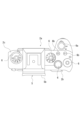
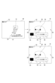
- FIG. 1 is a diagram showing the appearance of an imaging device according to the present embodiment.
- FIG. 1 is a diagram showing the appearance of an imaging device according to the present embodiment.
- 1 is a diagram showing the internal configuration of an imaging device.
- FIG. 3 is a diagram showing recognizable parts for each type of subject.
- FIG. 6 is a diagram illustrating an enlarged focus display when a control target region is recognized.
- FIG. 6 is a diagram illustrating focus magnification display when a subject is not recognized.
- FIG. 3 is a diagram illustrating focus enlargement and return.
- FIG. 6 is a diagram illustrating switching on/off of focus enlargement and return.
- 7 is a flowchart showing the flow of focus enlargement display processing.
- FIG. 7 is a diagram illustrating focus enlargement display in a modified example.
- FIG. 7 is a diagram illustrating focus enlargement display in a modified example.
- image includes both still images and moving images.
- image refers not only to the state displayed on the display section, but also to the image data that is not displayed on the display section.
- subject refers not only to the object imaged by the imaging device 1, but also includes the image of the object captured in the image. Further, the “subject” includes not only people but also various objects such as animals, birds, insects, cars, trains, etc., and also includes parts (parts) of these objects.
- subject type indicates the type or type of the subject, such as a person, animal, bird, insect, car, or train. Further, one subject type may include a plurality of (two or more) subject types.
- the subject types may include a separate subject type (kingfisher) that is included in one subject type (bird), such as a relationship between "bird” and “kingfisher.”
- Image processing refers to a series of processes in which an image signal is read out from an image sensor in response to a predetermined operation, such as a full press of the shutter button, and after performing predetermined signal processing, it is recorded on a recording medium as image data. It refers to The "imaging instruction” refers to an operation for performing imaging processing, such as a full-press operation of a shutter button, for example.
- Configuration of imaging device> 1 and 2 are diagrams showing the appearance of an imaging device 1 according to this embodiment. Note that the following description will be made with the subject side as the front and the imager side as the rear.
- the imaging device 1 includes a camera casing 2 in which necessary parts are arranged inside and outside, and a lens mirror that is detachable from the camera casing 2 and attached to the front part 2a.
- a cylinder 3 is provided.
- FIG. 2 shows the camera housing 2 with the lens barrel removed. Note that the lens barrel 3 may be detachably attached as a so-called interchangeable lens, but may be a lens barrel that cannot be removed from the camera housing 2.
- a rear monitor 4 is arranged on the rear surface portion 2b of the camera housing 2.
- the rear monitor 4 displays live view images, reproduced images of recorded images, and the like.
- the rear monitor 4 is configured by a display device such as a liquid crystal display (LCD) or an organic EL (electro-luminescence) display, for example.
- the rear monitor 4 is rotatable with respect to the camera housing 2.
- the lower end of the rear monitor 4 can be rotated using the upper end of the rear monitor 4 as a rotation axis so that the lower end of the rear monitor 4 moves rearward.
- the right end or left end of the rear monitor 4 may be used as a rotation axis.
- it may be rotatable in directions around a plurality of axes.
- An EVF (Electric Viewfinder) 5 is arranged on the upper surface 2c of the camera housing 2.
- the EVF 5 includes an EVF monitor 5a and a frame-shaped enclosure 5b that protrudes rearward so as to surround the upper and left and right sides of the EVF monitor 5a.
- the EVF monitor 5a is formed using an LCD, an organic EL display, or the like. Note that an optical view finder (OVF) may be provided instead of the EVF monitor 5a.
- OVF optical view finder
- buttons include a shutter button (release button), a playback menu activation button, a decision button, a cross key, a cancel button, a zoom key, a slide key, and the like.
- These operators 6 include various types of operators, such as buttons, dials, and complex operators that can be pressed and rotated.
- Various types of operators 6 enable, for example, shutter operation, menu operation, playback operation, mode selection/switching operation, focus operation, zoom operation, and parameter selection/setting such as shutter speed and F-number.
- the operators 6 include, for example, a shutter button 6a, a plurality of custom buttons 6b, an upper button 6c, a lower button 6d, a right button 6e, a left button 6f, a decision button 6g, a menu button 6h, and a function button 6i. .
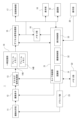
- FIG. 3 is a diagram showing the internal configuration of the imaging device 1.
- the imaging device 12 which is constituted by, for example, a CMOS (Complementary Metal Oxide Semiconductor) sensor or a CCD (Charge Coupled Device) sensor, through an imaging optical system 11, and 12, the signal is photoelectrically converted, and an analog image signal is obtained from the image sensor 12.
- CMOS Complementary Metal Oxide Semiconductor
- CCD Charge Coupled Device
- the imaging optical system 11 is provided with various lenses such as a zoom lens, a focus lens, and a condensing lens, an aperture mechanism, a zoom lens drive mechanism, and a focus lens drive mechanism.
- a mechanical shutter may also be provided.
- the image sensor 12 has a plurality of two-dimensional pixels, each having a photodiode (photogate), a transfer gate (shutter transistor), a switching transistor (address transistor), an amplification transistor, a reset transistor (reset gate), etc., on a CMOS substrate, for example.
- a vertical scanning circuit, a horizontal scanning circuit, and an image signal output circuit are formed.
- the image sensor 12 may be either a primary color system or a complementary color system, and the analog image signal obtained from the image sensor 12 is a primary color signal of each RGB color or a complementary color system color signal.
- the image sensor 12 may be configured without a color filter so that the analog image signal obtained from the image sensor 12 is a black and white image signal.
- the analog image signal from the image sensor 12 is sampled and held for each color signal in an analog signal processing unit 13 configured as an IC (Integrated circuit), and the amplitude is adjusted by AGC (Automatic Gain Control).
- AGC Automatic Gain Control
- the image signal is adjusted and converted into a digital image signal by A/D (Analog to Digital) conversion.
- a digital image signal (hereinafter referred to as image data) from the analog signal processing section 13 is input to the temporary storage section 14 .
- image data A digital image signal (hereinafter referred to as image data) from the analog signal processing section 13 is input to the temporary storage section 14 .
- the image sensor 12, the analog signal processing section 13, or even the temporary storage section 14 may be integrated.
- a frame memory described below as the temporary storage section 14 may be provided within the stacked image sensor.
- the temporary storage unit 14 includes two frame memories 14A and 14B in this example.
- Image data from the analog signal processing section 13 is stored alternately in the frame memory 14A and the frame memory 14B. That is, the temporary storage unit 14 stores two consecutively captured image frames.
- the image data stored in the temporary storage section 14 is sequentially output to the digital signal processing section 15 from the preceding storage frame. That is, image data is sequentially output from the frame memory 14A and the frame memory 14B to the digital signal processing unit 15 alternately in accordance with the imaging order.
- the digital signal processing unit 15 is configured as an image processing processor using, for example, a DSP (Digital Signal Processor). This digital signal processing section 15 performs various signal processing on input image data. For example, as a camera process, the digital signal processing unit 15 performs preprocessing, synchronization processing, YC generation processing, etc. In addition, the digital signal processing unit 15 performs file formation processing on the image data that has been subjected to these various processes, such as compression encoding for recording and communication, formatting, and generation and addition of metadata, and records the data. Generates files for use and communication. For example, an image file in a format such as JPEG, TIFF (Tagged Image File Format), or GIF (Graphics Interchange Format) is generated as a still image file.
- JPEG Joint Photographics Interchange Format
- the digital signal processing unit 15 also performs resolution conversion processing on image data (input images) that have been subjected to various signal processing, and converts the image data to a lower resolution in order to display a live view image, for example. generate.
- the memory unit 16 is a buffer memory for image data.
- This memory section 16 is composed of, for example, a D-RAM (Dynamic Random Access Memory).
- the image data processed by the digital signal processing section 15 is temporarily stored in the memory section 16, and is transferred to the recording control section 17, the display section 18, or the communication section 19 at a predetermined timing.
- the recording control unit 17 performs recording and reproduction on a recording medium such as a nonvolatile memory.
- the recording control unit 17 performs processing for recording image files such as moving image data and still image data onto a recording medium, for example.
- the actual form of the recording control section 17 can be considered in various ways.
- the recording control unit 17 may be configured as a flash memory built into the imaging device 1 and its writing/reading circuit.
- the recording control unit 17 may also be configured as a card recording/reproducing unit that performs recording/reproducing access to a recording medium that can be attached to and detached from the imaging device 1, such as a memory card (portable flash memory, etc.).
- the recording control unit 17 may be implemented as a built-in form of an HDD (Hard Disk Drive) in the imaging device 1.
- HDD Hard Disk Drive
- the display unit 18 is a display unit that displays various displays to the user, and is, for example, the back monitor 4 or EVF 5 arranged in the housing of the imaging device 1 as shown in FIG.
- the display unit 18 executes various displays on the display screen based on instructions from the camera control unit 21.
- the display unit 18 displays a reproduced image of the image data read from the recording medium by the recording control unit 17.
- the display unit 18 is supplied with image data of a captured image whose resolution has been converted for display by the digital signal processing unit 15, and displays a display corresponding to the image data, that is, a live view image.
- the display unit 18 displays various operation menus, icons, messages, etc., ie, a GUI (Graphical User Interface), on the screen based on instructions from the camera control unit 21.
- GUI Graphic User Interface
- the communication unit 19 performs data communication and network communication with external devices by wire or wirelessly. For example, image data (still image files and video files) and metadata are transmitted and output to external information processing devices, display devices, recording devices, playback devices, and the like. Further, the communication unit 19 serves as a network communication unit, and performs various network communications such as the Internet, a home network, and a LAN (Local Area Network), and sends and receives various data to and from servers, terminals, etc. on the network. I can do it.
- network communications such as the Internet, a home network, and a LAN (Local Area Network)
- the operation unit 20 collectively represents input devices through which the user performs various operation inputs.
- the operation unit 20 is various types of operators 6 provided on the casing of the imaging device 1 .
- the operating elements 6 corresponding to the operating unit 20 include, for example, a touch panel provided on the rear monitor 4 and a touch pad.
- the operation section 20 may be configured as a receiving section for receiving operation signals from a remote controller. The operation unit 20 detects a user's operation, and a signal corresponding to the input operation is sent to the camera control unit 21.
- the camera control section 21 is constituted by a microcomputer (arithmetic processing unit) equipped with a CPU (Central Processing Unit).
- the camera control unit 21 is an imaging control device that controls the operation of the imaging device 1.
- the memory section 22 stores information and the like used by the camera control section 21 for processing.
- ROM Read Only Memory
- RAM Random Access Memory
- flash memory etc. are comprehensively shown.
- the memory section 22 may be a memory area built into a microcomputer chip as the camera control section 21, or may be constituted by a separate memory chip.
- the camera control unit 21 controls the entire imaging device 1 by executing programs stored in the ROM, flash memory, etc. of the memory unit 22.
- the camera control unit 21 controls various signal processing instructions in the digital signal processing unit 15, imaging operations and recording operations in response to user operations, playback operations of recorded image files, and the like.
- the camera control unit 21 also controls the operation of the aperture mechanism, the shutter speed of the image sensor 12, and the AGC gain control in the analog signal processing unit 13 as automatic exposure control. Further, the camera control unit 21 performs drive control of a focus lens and a zoom lens in response to autofocus control, manual focus operation, zoom operation, and the like. Further, the camera control unit 21 controls the shutter speed, exposure timing, etc. of the image sensor 12.
- the camera control section 21 is provided with functions as a recognition section 31, an imaging control section 32, and a display control section 33.
- the recognition unit 31 performs a process of recognizing a subject (control target part) based on an input image.
- the imaging control unit 32 performs processing to control each unit regarding imaging.
- the display control unit 33 performs display control of images displayed on the display unit 18. Note that the processing performed by the recognition unit 31, the imaging control unit 32, and the display control unit 33 will be described in detail later.
- the RAM in the memory unit 22 is used to temporarily store data, programs, etc. as a work area when the CPU of the camera control unit 21 processes various data.
- the ROM and flash memory (non-volatile memory) in the memory unit 22 are used to store an OS (Operating System) for the CPU to control various parts, application programs for various operations, firmware, various setting information, etc. used.
- OS Operating System
- Various types of setting information include communication setting information, setting information regarding imaging operation, setting information regarding image processing, and the like.
- Setting information regarding the imaging operation includes exposure settings, shutter speed settings, mechanical shutter or electronic shutter curtain speed settings, mode settings, and the like.
- the driver section 23 is provided with, for example, a motor driver for a zoom lens drive motor, a motor driver for a focus lens drive motor, a motor driver for an aperture mechanism motor, and the like. These motor drivers apply drive current to the corresponding drivers in response to instructions from the camera control unit 21 (imaging control unit 32) to move the focus lens and zoom lens, open and close the aperture blades of the aperture mechanism, etc. It turns out.
- the camera control unit 21 performs recognition processing to recognize a subject (control target part) of a subject type to be recognized among a plurality of subject types from a live view image.
- the object recognized here becomes, for example, an object to be focused on in autofocus control, or an object to be tracked.
- subject types include "people,” “animals,” “birds,” “insects,” and “cars/trains.”
- “Animal” is a species in which the subject is a mammal other than a person, such as a mammal that is a pet such as a dog or a cat, or a mammal that is a wild animal.
- “Bird” is a species in which the subject is a bird.
- “Car/Train” is a type in which the subject is a car (automobile) or a train.
- animal + bird is provided as the subject type.
- Animal+bird includes the above-described subject types “animal” and “bird”. That is, “animal + bird” is a species in which the subject is a mammal other than a person or a bird. In this way, the subject types may include a plurality of subject types.
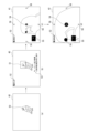
- FIG. 4 is a diagram showing recognizable parts for each type of subject.
- a recognizable part is shown surrounded by a square.
- parts that can be recognized in recognition processing are determined in advance for each type of subject.
- recognizable parts for the subject types "person”, “animal”, and “bird”, “eyes”, “face”, “head”, and “body” are provided as recognizable parts.
- the recognizable parts "face” and “head” are recognized as the same part, and hereinafter, they will be collectively referred to as “head.”
- the recognizable parts “face” and “head” may be recognized as different parts.
- the subject types “person”, “animal”, and “bird”, “right eye” and “left eye” are provided as recognizable parts, and these can be switched.
- the imaging device 1 determines and registers control target parts from among the recognizable parts for each subject type.
- the control target part indicates which part is the control target among the recognizable parts, and the recognizable parts "pupils", “head”, and “body” can be determined individually. It is also possible to determine combinations of a plurality of recognizable parts, specifically “pupils + head” and “auto (pupils + head + body)".
- the control target part “pupil + head” includes “pupil” and “head” as control target parts, and “pupil” is given priority over “head”.
- the control target part “Auto” includes “pupil", “head”, and “body” as control target parts, and “pupil” is given priority over “head", and "head” is " priority over the body.
- the recognition unit 31 recognizes the subject and the recognizable parts of the subject through recognition processing for each subject type.
- the recognition process is performed using, for example, an algorithm learned by deep learning such as CNN (Convolutional Neural Network).
- CNN Convolutional Neural Network
- an algorithm learned in advance by deep learning or the like is stored in the memory unit 22 for each type of subject.
- the type of subject and the region to be controlled are selected in advance by the user.
- the recognition unit 31 recognizes the subject and the recognizable parts using an algorithm of a preselected subject type. Therefore, in the recognition process, while it is possible to recognize a subject of a subject type that is a recognition target, it is not possible to recognize a subject of a subject type that is not a recognition target. Then, for example, when a recognizable part set as a control target part is recognized in the image, the imaging control unit 32 performs autofocus control to focus on that part.
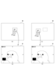
- FIG. 5 is a diagram illustrating an enlarged focus display when a control target region is recognized.
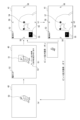
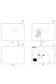
- FIG. 6 is a diagram illustrating the focus magnification display when the subject is not recognized.
- the camera control unit 21 When the user performs a predetermined operation while displaying the live view image 40 based on the input image, the camera control unit 21 performs focus enlargement display processing to enlarge and display a part of the live view image 40. For example, execution of the focus enlargement display process is assigned in advance to one of the custom buttons 6b. Then, when the custom button 6b assigned to execute the focus enlargement display process is operated while the live view image 40 is being displayed, the camera control unit 21 performs the focus enlargement display process.
- the display control unit 33 recognizes the part to be controlled in the live view image 40 as shown in FIG. 5(a).
- a recognition frame 50 is displayed on the control target part.
- the display control unit 33 displays the control target part on the live view image 40, as shown in FIG. 5(b).
- An enlarged frame 51 that has a predetermined display magnification is displayed in a superimposed manner centered on .
- the display control unit 33 may continue to display the recognition frame 50 when the enlarged frame 51 is displayed.
- the display control unit 33 also displays an enlargement ratio icon 52 indicating the enlargement ratio of the image (live view image 40, first enlarged image 41, or second enlarged image 42) to be displayed on the display unit 18 (rear monitor 4). .
- "1.0" times is displayed as the enlargement magnification icon 52.
- the display control unit 33 displays an operation guide 53 indicating the type of the operator 6 and the content to be executed by operating the operator 6.
- the display control unit 33 controls the display of the live view image 40 as shown in FIG. 5(c).
- the image portion indicated by the enlargement frame 51 is enlarged and displayed on the entire display section 18. That is, the display control unit 33 displays an image portion of the live view image 40 that has been enlarged at a predetermined magnification (in this case, 5.0 times) with the control target region as the first enlarged image 41 on the display unit. 18. That is, the display control unit 33 causes the display unit 18 to display, as the first enlarged image 41, an image portion centered on the recognized control target region among the recognizable regions according to the type of subject selected by the user.
- a predetermined magnification in this case, 5.0 times
- the display control unit 33 determines the area (part) of the subject to be displayed as the first enlarged image 41 according to the subject type. Further, the display control unit 33 displays the enlargement magnification icon 52, the image center mark 54, the enlarged position display area 55, and the movement display icon 56 in a superimposed manner on the first enlarged image 41.
- the image center mark 54 is a mark pointing to the center of the first enlarged image 41 or the second enlarged image 42, and is, for example, a cross mark.
- the enlarged position display area 55 is displayed at the lower left of the display section 18.
- the black portion indicates the imaging range of the live view image 40
- the white frame indicates the display range of the first enlarged image 41 or the second enlarged image 42. Therefore, the enlarged position display area 55 indicates the position of the first enlarged image 41 or the second enlarged image 42 in the live view image 40.
- the live view image 40 may be displayed in a reduced size instead of being painted black in the enlarged position display area 55.
- the display position of the enlarged position display area 55 on the display unit 18 may be changed depending on the position of the subject in the first enlarged image 41 or the second enlarged image 42. Specifically, the enlarged position display area 55 may be displayed at a position that does not overlap with the subject in the first enlarged image 41 or the second enlarged image 42.
- the movement display icons 56 are displayed on the top, bottom, left and right sides of the display unit 18, and indicate that the image portion of the live view image 40 displayed as the first enlarged image 41 or the second enlarged image 42 can be moved.
- the display control unit 33 displays a second enlarged image in which a part of the live view image 40 is further enlarged (in this case, 10 times) with the center of the first enlarged image 41 as a reference.
- the image 42 is displayed on the display unit 18. Further, the display control unit 33 displays the enlargement magnification icon 52, the image center mark 54, the enlarged position display area 55, and the movement display icon 56 in a superimposed manner on the second enlarged image 42.
- the imaging control section 32 controls the first enlarged image 41 or the second enlarged image 42. 2. Each part is controlled so that the subject corresponding to the center of the enlarged image 42 is brought into focus. Note that the imaging control unit 32 controls each unit so that the focus is not on the center of the first enlarged image 41 or the second enlarged image 42 but on the focus target determined by autofocus control for the live view image 40. You may also do so.
- the user can check the focus position, the current degree of focus, etc. in the enlarged image.
- the user operates the upper button 6c, lower button 6d, right button 6e, and left button 6f to view the live view.
- the position where the first enlarged image 41 or the second enlarged image 42 in the image 40 is displayed in an enlarged manner is moved. That is, the user can change the focus position and the like by moving the image portion displayed in the first enlarged image 41 or the second enlarged image 42.
- the recognition frame 50 is not displayed in the live view image 40, as shown in FIG. 6(a).
- the display control unit 33 adds the live view image to the live view image 40, as shown in FIG. 6(b).
- An enlarged frame 51 having a predetermined display magnification based on the center of 40 is displayed in a superimposed manner.
- the display control unit 33 selects one of the live view images 40 as shown in FIG. 6(c).
- the image portion indicated by the enlarged frame 51 is displayed on the display section 18 as the first enlarged image 41. That is, the display control unit 33 causes the display unit 18 to display the first enlarged image 41 in which the center portion of the live view image 40 is enlarged. Further, the display control unit 33 displays the enlargement magnification icon 52, the image center mark 54, the enlarged position display area 55, and the movement display icon 56 in a superimposed manner on the first enlarged image 41.
- the display control unit 33 displays a second enlarged image 42 in which a part of the live view image 40 is further enlarged based on the center of the first enlarged image 41 on the display unit 18, as shown in FIG. 6(d). Display. Further, the display control unit 33 displays the enlargement magnification icon 52, the image center mark 54, the enlarged position display area 55, and the movement display icon 56 in a superimposed manner on the second enlarged image 42.
- the central portion of the live view image 40 is displayed in an enlarged manner. Then, for example, by operating the upper button 6c, lower button 6d, right button 6e, and left button 6f, the position displayed by the first enlarged image 41 or the second enlarged image 42 in the live view image 40 is moved. That is, the user can change the focus position, etc. by moving the position of the first enlarged image 41 or the second enlarged image 42.
- a part (image portion) of the live view image 40 is enlarged and displayed as the first enlarged image 41 or the second enlarged image 42. Then, when the shutter button 6a is operated (fully pressed) while the first enlarged image 41 or the second enlarged image 42 is displayed on the display section 18, imaging processing is performed.
- an image signal is read from the image sensor 12, subjected to predetermined image processing, and then the image data is recorded on a recording medium. Note that the image recorded as image data at this time is not the image portion enlarged and displayed in the first enlarged image 41 or the second enlarged image 42, but is captured by the image sensor 12, which corresponds to the live view image 40. This is the entire image.
- the first enlarged image 41 and the second enlarged image 42 are enlarged so that the user can confirm a part of the image to be recorded, and are enlarged to record only that part. isn't it.
- the display control unit 33 controls the double-tap.
- the first enlarged image 41 or the second enlarged image 42 may be displayed centering on the image portion that has been enlarged.
- the display control unit 33 displays the first enlarged image 41 or the second enlarged image 42 with the subject as the center. You may also do so.
- the display control unit 33 displays the first enlarged image 41 or the second enlarged image after the imaging instruction by turning on/off the focus enlargement return set in advance. It is possible to selectively control whether or not 42 is displayed continuously.
- FIG. 7 is a diagram illustrating focus enlargement and return. Note that since FIGS. 7(a) to 7(c) are the same as FIGS. 5(a) to 5(c), the description thereof will be omitted.
- the first enlarged image 41 is displayed as shown in FIG. 7(d).
- the subject corresponding to the center of the enlarged image 41 is focused.
- the display control unit 33 also causes a focus mark 57 to be displayed at the focused position to indicate that the image is in focus.
- the imaging control unit 32 captures an image focused on the subject corresponding to the center of the first enlarged image 41, and records it on the recording medium as image data.
- the focus enlargement return is a function of continuously displaying the first enlarged image 41 or the second enlarged image 42 that has been displayed so far after an imaging instruction is given.
- the first enlarged image 41 shown in FIG. 7(c) is continuously displayed on the display unit 18 after the imaging instruction is given.
- the display control unit 33 displays the first enlarged image after displaying the image recorded in the imaging process (the entire image) on the display unit 18 for a predetermined period of time. 41 is displayed.
- “to continuously display the first enlarged image 41 or the second enlarged image 42” means to display the first enlarged image 41 or the second enlarged image 42 on the display unit 18 even if no user operation is performed. It refers to letting someone do something.
- “to continuously display the first enlarged image 41 or the second enlarged image 42” means to display the first enlarged image 41 or the second enlarged image 42 on the display unit 18 even if no user operation is performed. It can also be said that it is restarted. Further, the first enlarged image 41 or the second enlarged image 42 that is displayed after the imaging instruction is the first enlarged image 41 or the second enlarged image 42 that is displayed when the display is restarted.
- a black image (mute image) is temporarily displayed when imaging processing is performed, etc. Even if an image of This includes continuously displaying the image 42. Furthermore, in the imaging device 1 in which so-called blackout does not occur during continuous shooting (continuous shooting), the live view image 40 is temporarily displayed before the first enlarged image 41 or the second enlarged image 42 is displayed. However, such a case is also included in continuing (resuming) the first enlarged image 41 or the second enlarged image 42.
- the first enlarged image 41 when displaying the first enlarged image 41 continuously, an image portion in the same range as the range in the live view image 40 of the first enlarged image 41 that was displayed before the imaging instruction is displayed. That is, if the imaging device 1 and the subject do not move before and after the imaging process, the first enlarged image 41 that is displayed again will show the same subject as before the imaging process.
- the display control unit 33 displays a live view image as shown in FIG. 7A instead of the first enlarged image 41 or the second enlarged image 42 displayed after the imaging instruction 40 is displayed on the display unit 18. Therefore, when the focus enlargement return is off, the display control unit 33 terminates the focus enlargement display process and displays the live view image without restarting the display of the first enlarged image 41 or the second enlarged image 42 after the imaging instruction. 40 is displayed on the display unit 18.
- FIG. 8 is a diagram illustrating switching on/off of focus enlargement return. As shown in FIG. 8A, the operation guide 53 displays that the focus enlargement return can be turned on or off by operating the function button 6i.
- the display control unit 33 displays a message indicating that the focus enlargement return is turned on, as shown in FIG. 8(b).
- a display switching guide 58 marked ":ON" is displayed.
- the display control unit 33 displays a message indicating that the focus enlargement return is turned off, as shown in FIG. 8(c).
- a display switching guide 58 labeled ": Off” is displayed.
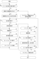
- FIG. 9 is a flowchart showing the flow of focus enlargement display processing.
- the display control unit 33 determines whether the custom button 6b to which execution of the focus enlargement display process is assigned has been operated (whether there has been an operation to execute the focus enlargement display process). Step S1 is then repeated until the custom button 6b assigned to execute the focus enlargement display process is operated.
- step S1 When the custom button 6b assigned to execute the focus magnification display process is operated (Yes in step S1), the display control unit 33 displays the control target recognized by the recognition unit 31 in the live view image 40 in step S2. Determine whether a part (subject) is present. As a result, if there is a recognized part to be controlled (Yes in step S2), the display control unit 33 superimposes an enlarged frame 51 centered on the recognized part to be controlled on the live view image 40 in step S3. Display. On the other hand, if there is no recognized part to be controlled (No in step S2), the display control unit 33 displays an enlarged frame 51 with the center of the live view image 40 as a reference in step S4.
- step S5 the display control unit 33 determines whether the custom button 6b or the enter button 6g, to which execution of the focus enlargement display process has been assigned, has been operated, that is, whether an operation for enlargement display has been performed. As a result, if no operation for enlarged display has been performed (No in step S5), step S6 is skipped and the process moves to step S7.
- step S5 when an operation for enlarged display is performed (Yes in step S5), the display control unit 33 controls in step S6 that when the live view image 40 is displayed, the first enlarged image 41 and the first enlarged image 41 are When displayed, the second enlarged image 42 is displayed.
- step S7 the display control unit 33 determines whether the upper button 6c, lower button 6d, right button 6e, or left button 6f has been operated, that is, whether an operation to move the image portion to be enlarged and displayed has been performed. As a result, if the operation to move the image portion to be enlarged and displayed has not been performed (No in step S7), step S8 is skipped and the process moves to step S9.
- step S7 if an operation to move the portion to be enlarged is performed (Yes in step S7), the display control unit 33 in step S8 responds to the operations of the upper button 6c, lower button 6d, right button 6e, and left button 6f. Then, the image portion of the live view image 40 to be enlarged and displayed is moved to display the first enlarged image 41 or the second enlarged image 42.
- step S9 the imaging control unit 32 determines whether an operation for performing autofocus has been performed, such as pressing the shutter button 6a halfway. As a result, if no operation for performing autofocus is performed (No in step S9). Step S10 is skipped and the process moves to step S11.
- step S9 the imaging control unit 32 performs autofocus control to focus on a predetermined subject in step S10.
- the display control unit 33 focuses on the center of the first enlarged image 41 or the second enlarged image 42, or focuses on a recognized control target region.
- step S11 the imaging control unit 32 determines whether an imaging instruction operation for performing imaging processing, such as fully pressing the shutter button 6a, has been performed. As a result, if no operation for performing imaging processing has been performed (No in step S11), the processing in steps S12 to S14 is skipped and the processing moves to step S15.
- an imaging instruction operation for performing imaging processing such as fully pressing the shutter button 6a
- step S12 the imaging control unit 32 performs imaging processing to control each part to record image data on a recording medium.
- step S13 the display control unit 33 determines whether focus enlargement return is on. As a result, if the focus enlargement return is not on, that is, if the focus enlargement return is off (No in step S13), steps S14 and S15 are skipped and the process moves to step S16.
- the display control unit 33 displays the image stored in the storage medium in the imaging process on the display unit 18 in step S14, and then displays the image before the imaging instruction. Similarly, the first enlarged image 41 or the second enlarged image 42 is continuously displayed on the display unit 18.
- step S15 the display control unit 33 determines whether a predetermined operation has been performed to end the focus enlargement display process. If the operation for terminating the focus magnification display process has not been performed (No in step S15), the process returns to step S5.
- step S15 if the focus enlargement return is off (No in step S13) and if an operation to end the focus enlargement display process is performed (Yes in step S15), the display control unit 33 in step S16 The live view image 40 is displayed on the display unit 18.
- the first enlarged image 41 and the second enlarged image 42 are provided as enlarged images.
- the enlarged image may be only one of the first enlarged image 41 and the second enlarged image 42, or three or more enlarged images with different magnifications may be provided.
- the shutter button 6a when the shutter button 6a is pressed halfway while the first enlarged image 41 or the second enlarged image 42 is displayed on the display unit 18, the first enlarged image 41 or the second enlarged image 42 I tried to focus on the center of the image.
- the control target region (subject) is recognized by the recognition unit 31
- the shutter button 6a is pressed halfway while the first enlarged image 41 or the second enlarged image 42 is displayed on the display unit 18. Then, the focus may be set on the recognized part to be controlled.
- the range in the live view image 40 that was displayed before the imaging instruction is The image area that is the same as the image area is now displayed enlarged.
- the display control part 33 controls the display control part 33 to control the part recognized by the recognition part 31 (out of the recognizable parts according to the subject type) after the imaging instruction.
- the first enlarged image 41 or the second enlarged image 42 may be displayed centering on the control target region).
- the first enlarged image 41 or the second enlarged image 42 may be displayed so that the control target region tracked by the recognition unit 31 is shown in the center.
- the recognition unit 31 recognizes the control target region (in this case, the bird's left eye), and the 1 enlarged image 41 is displayed on the display unit 18.
- the display control unit 33 moves the enlarged image portion and causes the display unit 18 to display a first enlarged image 41 centered on the control target region.
- the imaging device 1 can perform an enlarged display that follows the control target region.
- the display control unit 33 displays the first enlarged image 41 or the second enlarged image 42 centering on the image part centered on the focused subject after the imaging instruction. You can do it like this.
- the display control unit 33 displays an image portion in the same range as the range in the live view image 40 that was displayed before the imaging instruction, or
- the object (part to be controlled) recognized by the recognition unit 31 may be displayed as an enlarged image based on predetermined conditions.
- the predetermined conditions may include various conditions, such as displaying the first enlarged image 41 or the second enlarged image 42 based on conditions set by the user.
- the display control unit 33 displays an enlarged image (first enlarged The live view image 40 is displayed on the display unit 18 instead of the image 41 or the second enlarged image 42).
- the image 41 may be displayed on the display unit 18.
- the display control unit 33 After the instruction is given, it may be determined whether or not to continue displaying the enlarged image depending on the set mode.
- the display control unit 33 may determine whether to continue displaying the enlarged image after the imaging instruction is given, depending on the movement of the subject. For example, if the subject moves in small increments, it is necessary to focus each time, so displaying an enlarged image can make it easier to focus. Further, when the subject hardly moves, such as a landscape, refocusing is not necessary, so displaying the live view image 40 allows the user to check the entire scene.
- the imaging device 1 receives an imaging instruction while the display unit 18 is displaying an enlarged image (first enlarged image 41, second enlarged image 42) obtained by enlarging a part of the live view image 40 based on the input image. It includes a display control section 33 that causes the display section 18 to continuously display the enlarged image. As a result, the imaging device 1 can continue displaying the enlarged image even if an imaging instruction is given while the enlarged image is being displayed, for example when the user wants to record images continuously, and the user can view the enlarged live view. It becomes possible to check the image part of the image at any time. Therefore, the user can check the enlarged live view image without forcing the user to perform complicated operations.
- the display control unit 33 causes the display unit 18 to resume displaying the enlarged images (the first enlarged image 41 and the second enlarged image 42).
- the imaging device 1 can allow the user to check the enlarged live view image without forcing the user to perform complicated operations.
- the display control unit 33 can selectively control whether or not to continue displaying the enlarged images (the first enlarged image 41 and the second enlarged image 42) after the imaging instruction is given. Thereby, the imaging device 1 can display either the live view image 40 or the enlarged image on the display unit 18 after giving an imaging instruction, depending on the user's preference or the usage situation.
- the imaging device 1 includes a recognition unit 31 that recognizes a subject (part to be controlled) based on the input image, and the display control unit 33 displays images centered around the subject recognized by the recognition unit 31 in the live view image 40.
- the image portion is displayed on the display unit 18 as an enlarged image (first enlarged image 41, second enlarged image 42).
- the imaging device 1 can allow the user to easily confirm the subject to be focused by autofocus, for example.
- the display control unit 33 determines the area of the subject to be displayed as an enlarged image (first enlarged image 41, second enlarged image 42) according to the subject type. Thereby, it is possible to determine the optimum area to be enlarged depending on the type of subject.
- the display control unit 33 causes the display unit 18 to display, as an enlarged image, an image portion centered on the recognized control target region among the recognizable regions according to the type of the subject. Thereby, it is possible to enlarge one of the most suitable recognizable parts according to the type of subject and allow the user to check it.
- the control target part is selected by the user from the recognizable parts. Thereby, it is possible to enlarge the part that the user desires for the user to confirm.
- the display control unit 33 causes the display unit 18 to display an image portion centered on the in-focus subject as an enlarged image (first enlarged image 41, second enlarged image 42). Thereby, the imaging device 1 can allow the user to easily confirm the subject to be focused by autofocus, for example.
- the display control unit 33 displays enlarged images (a first enlarged image 41, a second enlarged image 42) to be displayed after the imaging instruction, for an image portion in the same range in the live view image 40 of the enlarged image that was displayed at the time of the imaging instruction. ) on the display unit 18.
- the imaging device 1 can allow the user to confirm the same range of the live view image 40 as an enlarged image before and after the imaging instruction is issued.
- the display control unit 33 displays enlarged images (first enlarged image 41, second enlarged image 41, second enlarged image 41, The enlarged image 42) is displayed on the display section 18. Thereby, when the imaging device 1 continuously images the same subject, it is possible for the user to check the image portion in which the subject recognized by the recognition unit 31 is captured in an enlarged image before and after the imaging process.
- the display control unit 33 determines the area of the subject to be displayed as an enlarged image (first enlarged image 41, second enlarged image 42) to be displayed after the imaging instruction is given, according to the type of the subject. This makes it possible to determine the optimal enlargement area depending on the type of subject.
- the display control unit 33 displays an enlarged image (a first enlarged image 41, a second enlarged image 42) that is displayed after an imaging instruction for an image portion centered on the recognized control target region among the recognizable regions according to the type of the subject. ) on the display unit 18. Thereby, it is possible to enlarge one of the most suitable recognizable parts according to the type of subject and allow the user to check it.
- the control target part is selected by the user from the recognizable parts. Thereby, it is possible to enlarge the part that the user desires for the user to confirm.
- the display control unit 33 causes the display unit 18 to display an image portion centered on the focused subject as an enlarged image that is displayed after the imaging instruction is issued. Thereby, the imaging device 1 can allow the user to easily confirm the subject to be focused by autofocus, for example.
- the display control unit 33 displays the same range in the live view image 40 of the enlarged image that was displayed at the time of the imaging instruction, or the image portion of the live view image 40 centered on the subject recognized by the recognition unit 31. is displayed on the display section 18 as an enlarged image that is displayed after an imaging instruction is given according to predetermined conditions. Thereby, the imaging device 1 can display the original position or subject as an enlarged image after imaging processing, depending on the user's preference or the usage situation.
- the display control unit 33 displays the live view image 40 on the display unit 18 instead of the enlarged image displayed after the imaging instruction when the subject is removed from the live view image 40, and when the subject is within the live view image 40, The image portion centered on is displayed on the display section 18 as an enlarged image (first enlarged image 41, second enlarged image 42) to be displayed after the imaging instruction is given.
- the imaging device 1 searches for the subject by, for example, moving the image portion displayed in the enlarged image. It is possible to avoid unnecessary operations.
- the display control unit 33 determines whether to continue displaying the enlarged images (the first enlarged image 41 and the second enlarged image 42) after the imaging instruction is given, depending on the movement of the subject. Thereby, the imaging device 1 can magnify and display the subject to make it easier to focus when the subject moves in small increments, so when the subject needs to be focused each time. Further, when the subject hardly moves, such as a landscape, the imaging device 1 does not require refocusing, so the live view image 40 can be displayed to allow the user to check the entire scene. In this way, by displaying the live view image 40 or the enlarged image according to the movement of the subject, the user can confirm a more optimal image.
- the display control unit 33 transitions the display from the enlarged images (first enlarged image 41, second enlarged image 42) to the live view image 40, or Whether or not to continue displaying the enlarged image after the imaging instruction is given is determined according to the set mode.
- the imaging device 1 can optimally display a live view image or an enlarged image depending on the mode.
- the imaging control method includes displaying an enlarged image after an imaging instruction is given while the display unit 18 is displaying an enlarged image (a first enlarged image 41, a second enlarged image 42) obtained by enlarging a part of a live view image 40 based on an input image. section 18 to continue displaying. Further, the program displays the enlarged image after an imaging instruction is given while the display unit 18 is displaying an enlarged image (first enlarged image 41, second enlarged image 42) that is an enlarged part of the live view image 40 based on the input image. The computer is caused to perform a process of causing the section 18 to continue displaying the information.
- the program of the embodiment is a program that causes a processor such as a CPU or a DSP, or a device including these, to execute the above image processing.
- Such a program can be recorded in advance in an HDD as a recording medium built into equipment such as a computer device, or in a ROM in a microcomputer having a CPU.
- such programs can be used for flexible discs, CD-ROMs (Compact Disc Read Only Memory), MO (Magneto Optical) discs, DVDs (Digital Versatile Discs), Blu-ray Discs (registered trademark), magnetic It can be stored (recorded) temporarily or permanently in a removable recording medium such as a disk, semiconductor memory, or memory card.
- a removable recording medium can be provided as so-called package software.
- a program In addition to installing such a program into a personal computer or the like from a removable recording medium, it can also be downloaded from a download site via a network such as a LAN (Local Area Network) or the Internet.
- LAN Local Area Network
- An imaging device comprising: a display control section that causes the display section to continuously display the enlarged image after an imaging instruction is given while the display section is displaying an enlarged image obtained by enlarging a part of a live view image based on an input image.
- the display control unit causes the display unit to resume displaying the enlarged image after the imaging instruction.
- the display control unit can selectively control whether or not to continue displaying the enlarged image after the imaging instruction.
- the display control unit causes the display unit to display an image portion of the live view image centered on the subject recognized by the recognition unit as the enlarged image.
- the imaging device described. The imaging device according to (4), wherein the display control unit determines the area of the subject to be displayed as the enlarged image according to the type of the subject. (6) The imaging device according to (5), wherein the display control unit causes the display unit to display, as the enlarged image, an image portion centered on the recognized control target site among the recognizable sites according to the type of the subject. (7) The imaging device according to (6), wherein the control target region is selected by the user from among recognizable regions.
- the imaging device according to any one of (1) to (3), wherein the display control unit causes the display unit to display an image portion centered on the focused subject as the enlarged image.
- the display control unit causes the display unit to display an image portion of the same range in the live view image of the enlarged image displayed at the time of the imaging instruction as the enlarged image to be displayed after the imaging instruction.
- the imaging device according to any one of 1) to (8).
- the display control unit causes the display unit to display an image portion of the live view image centered on the subject recognized by the recognition unit as the enlarged image that is displayed after the imaging instruction.
- the imaging device wherein the display control unit determines a region of the subject to be displayed as the enlarged image displayed after the imaging instruction, depending on the type of the subject. (12) (11) The display control unit causes the display unit to display an image portion centered on a recognized control target part among the recognizable parts according to the type of the subject as the enlarged image that is displayed after the imaging instruction. The imaging device described in . (13) The imaging device according to (12), wherein the control target region is selected by the user from among recognizable regions. (14) The image capture according to any one of (1) to (3), wherein the display control unit causes the display unit to display an image portion centered on the focused subject as the enlarged image that is displayed after the image capture instruction. Device.
- the display control unit may display an image portion of the enlarged image displayed at the time of the imaging instruction in the same range in the live view image, or the subject recognized by the recognition unit in the live view image. (3) to (8), (10) to (14), displaying an image portion centered on the image on the display section as the enlarged image displayed after the imaging instruction according to predetermined conditions; The imaging device described. (16) The display control unit causes the display unit to display the live view image in place of the enlarged image displayed after the imaging instruction when the subject is removed from the live view image, and the display control unit displays the live view image on the display unit in place of the enlarged image displayed after the imaging instruction, and displays the subject in the live view image.
- the imaging device according to any one of (3) to (15), wherein an image portion centered on the subject is displayed on the display section as the enlarged image that is displayed after the imaging instruction.
- the display control unit determines whether to continue displaying the enlarged image after the imaging instruction, depending on the movement of the subject.
- the display control unit may cause the display to transition from the enlarged image to the live view image depending on the mode, or transition the display from the enlarged image to the live view image after the imaging instruction.
- the imaging device according to any one of (3) to (17), wherein whether or not to continuously display the image is determined according to a set mode.
- An imaging control method comprising: after an imaging instruction is issued while a display unit is displaying an enlarged image obtained by enlarging a part of a live view image based on an input image, the enlarged image is continuously displayed on the display unit.
- a program that causes a computer to execute a process of continuously displaying the enlarged image on the display unit after an imaging instruction is given while the display unit is displaying an enlarged image obtained by enlarging a part of a live view image based on an input image.
- Imaging device 6 Operator 21 Camera control section 31 Recognition section 32 Imaging control section 33 Display control section
Landscapes
- Engineering & Computer Science (AREA)
- Multimedia (AREA)
- Signal Processing (AREA)
- Human Computer Interaction (AREA)
- Studio Devices (AREA)
Priority Applications (3)
| Application Number | Priority Date | Filing Date | Title |
|---|---|---|---|
| DE112023001646.1T DE112023001646T5 (de) | 2022-03-30 | 2023-03-09 | Bildgebungsvorrichtung, bildgebungssteuerungsverfahren und programm |
| JP2024511639A JPWO2023189366A1 (enExample) | 2022-03-30 | 2023-03-09 | |
| US18/839,683 US20250168490A1 (en) | 2022-03-30 | 2023-03-09 | Imaging device, imaging control method, and program |
Applications Claiming Priority (2)
| Application Number | Priority Date | Filing Date | Title |
|---|---|---|---|
| JP2022-056222 | 2022-03-30 | ||
| JP2022056222 | 2022-03-30 |
Publications (1)
| Publication Number | Publication Date |
|---|---|
| WO2023189366A1 true WO2023189366A1 (ja) | 2023-10-05 |
Family
ID=88200630
Family Applications (1)
| Application Number | Title | Priority Date | Filing Date |
|---|---|---|---|
| PCT/JP2023/009112 Ceased WO2023189366A1 (ja) | 2022-03-30 | 2023-03-09 | 撮像装置、撮像制御方法、プログラム |
Country Status (4)
| Country | Link |
|---|---|
| US (1) | US20250168490A1 (enExample) |
| JP (1) | JPWO2023189366A1 (enExample) |
| DE (1) | DE112023001646T5 (enExample) |
| WO (1) | WO2023189366A1 (enExample) |
Citations (4)
| Publication number | Priority date | Publication date | Assignee | Title |
|---|---|---|---|---|
| JP2011234083A (ja) * | 2010-04-27 | 2011-11-17 | Canon Inc | 撮像装置及びその制御方法 |
| JP2013034167A (ja) * | 2011-06-28 | 2013-02-14 | Sony Corp | 情報処理装置、情報処理方法およびプログラム |
| JP2016178440A (ja) * | 2015-03-19 | 2016-10-06 | キヤノン株式会社 | 表示制御装置およびその制御方法 |
| WO2020138497A1 (ja) * | 2018-12-28 | 2020-07-02 | 株式会社ニコン | 電子機器、カメラおよびプログラム |
Family Cites Families (5)
| Publication number | Priority date | Publication date | Assignee | Title |
|---|---|---|---|---|
| JP2008160744A (ja) * | 2006-12-26 | 2008-07-10 | Olympus Imaging Corp | 撮像装置 |
| US9661232B2 (en) * | 2010-08-12 | 2017-05-23 | John G. Posa | Apparatus and method providing auto zoom in response to relative movement of target subject matter |
| JP6512961B2 (ja) | 2015-06-24 | 2019-05-15 | キヤノン株式会社 | 撮像制御装置およびその制御方法、プログラム、並びに記憶媒体 |
| JP6918605B2 (ja) * | 2017-06-29 | 2021-08-11 | キヤノン株式会社 | 撮像制御装置、制御方法、プログラム、及び記憶媒体 |
| US10721393B2 (en) * | 2017-12-29 | 2020-07-21 | Axis Ab | Laser ranging and illumination |
-
2023
- 2023-03-09 JP JP2024511639A patent/JPWO2023189366A1/ja active Pending
- 2023-03-09 US US18/839,683 patent/US20250168490A1/en active Pending
- 2023-03-09 WO PCT/JP2023/009112 patent/WO2023189366A1/ja not_active Ceased
- 2023-03-09 DE DE112023001646.1T patent/DE112023001646T5/de active Pending
Patent Citations (4)
| Publication number | Priority date | Publication date | Assignee | Title |
|---|---|---|---|---|
| JP2011234083A (ja) * | 2010-04-27 | 2011-11-17 | Canon Inc | 撮像装置及びその制御方法 |
| JP2013034167A (ja) * | 2011-06-28 | 2013-02-14 | Sony Corp | 情報処理装置、情報処理方法およびプログラム |
| JP2016178440A (ja) * | 2015-03-19 | 2016-10-06 | キヤノン株式会社 | 表示制御装置およびその制御方法 |
| WO2020138497A1 (ja) * | 2018-12-28 | 2020-07-02 | 株式会社ニコン | 電子機器、カメラおよびプログラム |
Also Published As
| Publication number | Publication date |
|---|---|
| US20250168490A1 (en) | 2025-05-22 |
| JPWO2023189366A1 (enExample) | 2023-10-05 |
| DE112023001646T5 (de) | 2025-03-13 |
Similar Documents
| Publication | Publication Date | Title |
|---|---|---|
| JP4761146B2 (ja) | 撮像装置及びそのプログラム | |
| JP4214926B2 (ja) | 電子スチルカメラ | |
| US8988535B2 (en) | Photographing control method and apparatus according to motion of digital photographing apparatus | |
| JP2006025238A (ja) | 撮像装置 | |
| JP4548156B2 (ja) | カメラ装置、カメラ装置の自動焦点制御方法 | |
| KR101630287B1 (ko) | 손 떨림 보정 모듈을 구비하는 디지털 촬영 장치 및 이의 제어 방법 | |
| JP5957948B2 (ja) | 表示制御装置、表示制御方法および記録媒体 | |
| JP5245907B2 (ja) | 撮像装置、及び顔領域特定方法とプログラム | |
| JP2003262786A (ja) | 撮像装置及びその自動合焦方法 | |
| JP4673245B2 (ja) | 撮像装置及びその制御方法 | |
| JP2009017517A (ja) | 撮像装置 | |
| WO2023189366A1 (ja) | 撮像装置、撮像制御方法、プログラム | |
| WO2021140746A1 (ja) | 撮像装置、情報処理方法、プログラム | |
| JP7294392B2 (ja) | 撮像装置 | |
| US20260006309A1 (en) | Imaging device, imaging control method, and program | |
| JP4788172B2 (ja) | 撮像装置及びプログラム | |
| EP4503635A1 (en) | Imaging device, imaging control method, and program | |
| CN103167238B (zh) | 用于再现图像的方法和设备 | |
| KR101533279B1 (ko) | 영상의 흔들림을 판단하는 디지털 영상 신호 처리 장치의 제어 방법, 이를 기록한 기록 매체, 및 상기 제어 방법에 의해 실행하는 디지털 영상 신호 처리 장치 | |
| JP5077113B2 (ja) | 電子カメラ | |
| JP4473318B2 (ja) | デジタルカメラ | |
| JP2023105192A (ja) | 撮像装置 | |
| JP4622748B2 (ja) | 電子カメラ、出力制御方法、及びプログラム | |
| JP2007041097A (ja) | 電子カメラ、撮影方法、及びプログラム | |
| JP2013162453A (ja) | 撮像装置 |
Legal Events
| Date | Code | Title | Description |
|---|---|---|---|
| 121 | Ep: the epo has been informed by wipo that ep was designated in this application |
Ref document number: 23779392 Country of ref document: EP Kind code of ref document: A1 |
|
| WWE | Wipo information: entry into national phase |
Ref document number: 18839683 Country of ref document: US |
|
| ENP | Entry into the national phase |
Ref document number: 2024511639 Country of ref document: JP Kind code of ref document: A |
|
| WWE | Wipo information: entry into national phase |
Ref document number: 112023001646 Country of ref document: DE |
|
| WWP | Wipo information: published in national office |
Ref document number: 112023001646 Country of ref document: DE |
|
| 122 | Ep: pct application non-entry in european phase |
Ref document number: 23779392 Country of ref document: EP Kind code of ref document: A1 |
|
| WWP | Wipo information: published in national office |
Ref document number: 18839683 Country of ref document: US |