WO2023189013A1 - バルブ装置 - Google Patents
バルブ装置 Download PDFInfo
- Publication number
- WO2023189013A1 WO2023189013A1 PCT/JP2023/006122 JP2023006122W WO2023189013A1 WO 2023189013 A1 WO2023189013 A1 WO 2023189013A1 JP 2023006122 W JP2023006122 W JP 2023006122W WO 2023189013 A1 WO2023189013 A1 WO 2023189013A1
- Authority
- WO
- WIPO (PCT)
- Prior art keywords
- piston
- pressure chamber
- operating air
- cylinder chamber
- valve
- Prior art date
- Legal status (The legal status is an assumption and is not a legal conclusion. Google has not performed a legal analysis and makes no representation as to the accuracy of the status listed.)
- Ceased
Links
Images


Classifications
-
- F—MECHANICAL ENGINEERING; LIGHTING; HEATING; WEAPONS; BLASTING
- F16—ENGINEERING ELEMENTS AND UNITS; GENERAL MEASURES FOR PRODUCING AND MAINTAINING EFFECTIVE FUNCTIONING OF MACHINES OR INSTALLATIONS; THERMAL INSULATION IN GENERAL
- F16K—VALVES; TAPS; COCKS; ACTUATING-FLOATS; DEVICES FOR VENTING OR AERATING
- F16K31/00—Actuating devices; Operating means; Releasing devices
- F16K31/12—Actuating devices; Operating means; Releasing devices actuated by fluid
- F16K31/122—Actuating devices; Operating means; Releasing devices actuated by fluid the fluid acting on a piston
-
- F—MECHANICAL ENGINEERING; LIGHTING; HEATING; WEAPONS; BLASTING
- F16—ENGINEERING ELEMENTS AND UNITS; GENERAL MEASURES FOR PRODUCING AND MAINTAINING EFFECTIVE FUNCTIONING OF MACHINES OR INSTALLATIONS; THERMAL INSULATION IN GENERAL
- F16K—VALVES; TAPS; COCKS; ACTUATING-FLOATS; DEVICES FOR VENTING OR AERATING
- F16K27/00—Construction of housing; Use of materials therefor
- F16K27/02—Construction of housing; Use of materials therefor of lift valves
-
- F—MECHANICAL ENGINEERING; LIGHTING; HEATING; WEAPONS; BLASTING
- F16—ENGINEERING ELEMENTS AND UNITS; GENERAL MEASURES FOR PRODUCING AND MAINTAINING EFFECTIVE FUNCTIONING OF MACHINES OR INSTALLATIONS; THERMAL INSULATION IN GENERAL
- F16K—VALVES; TAPS; COCKS; ACTUATING-FLOATS; DEVICES FOR VENTING OR AERATING
- F16K31/00—Actuating devices; Operating means; Releasing devices
- F16K31/12—Actuating devices; Operating means; Releasing devices actuated by fluid
- F16K31/122—Actuating devices; Operating means; Releasing devices actuated by fluid the fluid acting on a piston
- F16K31/1221—Actuating devices; Operating means; Releasing devices actuated by fluid the fluid acting on a piston one side of the piston being spring-loaded
-
- F—MECHANICAL ENGINEERING; LIGHTING; HEATING; WEAPONS; BLASTING
- F16—ENGINEERING ELEMENTS AND UNITS; GENERAL MEASURES FOR PRODUCING AND MAINTAINING EFFECTIVE FUNCTIONING OF MACHINES OR INSTALLATIONS; THERMAL INSULATION IN GENERAL
- F16K—VALVES; TAPS; COCKS; ACTUATING-FLOATS; DEVICES FOR VENTING OR AERATING
- F16K31/00—Actuating devices; Operating means; Releasing devices
- F16K31/12—Actuating devices; Operating means; Releasing devices actuated by fluid
- F16K31/122—Actuating devices; Operating means; Releasing devices actuated by fluid the fluid acting on a piston
- F16K31/1225—Actuating devices; Operating means; Releasing devices actuated by fluid the fluid acting on a piston with a plurality of pistons
-
- F—MECHANICAL ENGINEERING; LIGHTING; HEATING; WEAPONS; BLASTING
- F16—ENGINEERING ELEMENTS AND UNITS; GENERAL MEASURES FOR PRODUCING AND MAINTAINING EFFECTIVE FUNCTIONING OF MACHINES OR INSTALLATIONS; THERMAL INSULATION IN GENERAL
- F16K—VALVES; TAPS; COCKS; ACTUATING-FLOATS; DEVICES FOR VENTING OR AERATING
- F16K31/00—Actuating devices; Operating means; Releasing devices
- F16K31/12—Actuating devices; Operating means; Releasing devices actuated by fluid
- F16K31/122—Actuating devices; Operating means; Releasing devices actuated by fluid the fluid acting on a piston
- F16K31/1226—Actuating devices; Operating means; Releasing devices actuated by fluid the fluid acting on a piston the fluid circulating through the piston
-
- F—MECHANICAL ENGINEERING; LIGHTING; HEATING; WEAPONS; BLASTING
- F16—ENGINEERING ELEMENTS AND UNITS; GENERAL MEASURES FOR PRODUCING AND MAINTAINING EFFECTIVE FUNCTIONING OF MACHINES OR INSTALLATIONS; THERMAL INSULATION IN GENERAL
- F16K—VALVES; TAPS; COCKS; ACTUATING-FLOATS; DEVICES FOR VENTING OR AERATING
- F16K41/00—Spindle sealings
- F16K41/10—Spindle sealings with diaphragm, e.g. shaped as bellows or tube
Definitions
- the present invention relates to a valve used for fluid control, and particularly to a valve device that can realize large flow rate control and high-speed response in order to control process gas, etc. of semiconductor manufacturing equipment.
- an air-driven valve is used, which is capable of increasing the movement stroke of the valve body and increasing the flow rate.
- This air-driven valve device uses an air cylinder actuator to press the valve body against the valve seat and separate it.
- the air cylinder mechanism is driven by the supply of operating air controlled by an external solenoid valve. and its cancellation. While increasing the driving force of the air cylinder is required to speed up the valve opening operation, it is also required to reduce the width of the valve device from the viewpoint of installation in an integrated gas system.
- a cylinder actuator is used as a valve opening/closing actuator.
- Patent Document 1 Conventionally, in a multi-stage cylinder actuator, an upper piston and a lower piston were manufactured separately, and then they were screwed together to connect them, and a passage was also provided for supplying operating air into the inside of this combined body (Patent Document 1) ).
- the upper and lower pistons were separated and not connected, but instead had their ends abutted against each other, and a passage for supplying operating air to the cylinder chambers of each stage was provided inside each cylinder. Therefore, a structure in which the contact points communicate with each other has also been adopted (Patent Documents 2 and 3).
- the response time that is, the time from receiving a command to open the valve until it actually opens, or the command to close the valve.
- the response time has increased.
- the present invention was made to solve this problem, and an object thereof is to provide a valve device that is capable of controlling a large flow rate and a high-speed response, and is easy to manufacture.
- the valve device of the present invention includes a valve body in which a first flow path and a second flow path are formed; A valve that cuts off and communicates between the first flow path and the second flow path by coming into contact with and separating from a valve seat provided horizontally at the opening of the first flow path.
- the multi-stage cylinder actuator is a cylindrical casing that extends upward from the valve body, has both ends closed by an upper end plate and a lower end plate, and has an interior divided into an upper cylinder chamber and a lower cylinder chamber by a partition plate; an upper stage that is slidably disposed within the upper stage cylinder chamber, is biased downward by an upper stage spring, and is driven upward by the pressure of operating air in the upper stage pressure chamber formed between the partition plate; piston and The cylinder is slidably disposed in the lower cylinder chamber, is urged downward by a lower spring, and is driven upward by the pressure of operating air in the lower pressure chamber formed between the lower end plate.
- a lower piston having an operation shaft that protrudes through the lower end plate and operates the position of the valve body, and an abutment shaft that protrudes through the partition plate and abuts the upper piston;
- the upper stage piston has an upper stage operating air passage inside that introduces operating air from the outside and supplies the operating air to the upper stage pressure chamber and the lower stage pressure chamber
- the lower piston has an internal lower operating air passage that communicates with the upper operating air passage at a contact portion between the upper piston and the contact shaft to introduce operating air and supply the operating air to the lower pressure chamber.
- the contact portion is characterized by being provided with an O-ring that prevents leakage of operating air while allowing relative displacement between the upper piston and the contact shaft.
- the upper piston has a fitting hole that fits into the abutting shaft of the lower piston, and the abutting portion is formed at the tip of the abutting shaft and at the back of the fitting hole, and the Preferably, the ring is disposed between an outer periphery of a reduced diameter portion provided at the tip of the abutment shaft and an inner periphery of the fitting hole.
- the upper operating air passage includes a main flow path provided on the central axis within the upper piston
- the lower operating air passage includes a main flow path provided on the central axis within the lower piston.
- At least one of the upper operating air passage and the lower operating air passage branches radially from the main flow passage when viewed from above, and faces the lower surface of the upper piston facing the upper pressure chamber or the lower pressure chamber.
- a configuration further including a plurality of branch channels opening on the lower surface of the lower piston can be preferably adopted.
- the number of branch passages is 3 or more, and when the lower operation air passage has the branch passage, the number of branch passages is 3 or more. It is preferable that there be.
- the casing further includes a second partition plate that divides the lower cylinder chamber from above into a first lower cylinder chamber and a second lower cylinder chamber
- the lower piston includes a first lower piston arranged in the first lower cylinder chamber and a second lower piston arranged in the second lower cylinder chamber, and the first lower piston and a second lower piston is fixedly connected to and integrally slidable through the second partition plate;
- the lower pressure chamber is formed between a first lower pressure chamber formed between the first lower piston and the second partition plate and between the second lower piston and the lower end plate. Consists of a second lower pressure chamber,
- the operating shaft may be provided on the second lower piston, and the contact shaft may be provided on the first lower piston.
- the casing further includes a third partition plate that divides the upper cylinder chamber from below into a first upper cylinder chamber and a second upper cylinder chamber
- the upper stage piston includes a first upper stage piston arranged in the first upper stage cylinder chamber and a second upper stage piston arranged in the second upper stage cylinder chamber, and the first upper stage piston and a second upper stage piston is fixedly connected to and integrally slidable through the third partition plate;
- the upper pressure chamber is a first upper pressure chamber formed between the first upper piston and the partition plate, and a first upper pressure chamber formed between the second upper piston and the third partition plate. Consisting of a second upper pressure chamber, It may also be a configuration.
- the valve body includes a support including a bellows that integrally seals the opening of the first flow path and the opening of the second flow path from the outside while allowing vertical movement of the valve body.
- a configuration that is attached to the mechanism can be preferably adopted.
- a valve device having a multistage cylinder actuator that separates an upper piston and a lower piston and supplies operating air by communicating operating air passages provided inside each piston, the upper piston and the lower piston Since an O-ring is provided at the abutting portion between the upper piston and the lower piston, it is possible to prevent operating air from leaking from the abutting portion of the upper piston and the lower piston while allowing the mutual interval fluctuation. Thereby, it is possible to prevent an imbalance between the operating pressures of the upper piston and the lower piston due to this leakage, and it is possible to increase the operating speed while ensuring ease of manufacture.
- each operating air passage has a main passage provided on the central axis within each piston, and radially branches from the main passage when viewed from above, and each has an opening on the lower surface of the piston facing the pressure chamber.
- the upper cylinder chamber is divided into two cylinder chambers, and the upper piston is configured to consist of two upper pistons arranged in each cylinder chamber, or the lower cylinder chamber is divided into two cylinder chambers,
- the lower stage piston By configuring the lower stage piston to include two upper stage pistons arranged in respective cylinder chambers, the driving force of the pistons can be increased.
- valve body by attaching the valve body to a support mechanism that includes a bellows, large flow rate control can be achieved while maintaining leakage prevention and durability of non-controlled fluid.
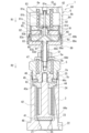
- FIG. 1 is a longitudinal sectional view showing a valve device according to a first embodiment of the present invention.
- FIG. 2 is a longitudinal cross-sectional view showing the valve device of FIG. 1 in a closed state.
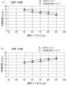
- FIG. 3 is a graph showing an example of the relationship between the operating time and operating air pressure of the valve device of this embodiment and the conventional valve device, in which (a) shows the valve opening time and (b) shows the valve closing time.
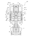
- FIG. 7 is a vertical sectional view showing the upper part of a valve device according to a second embodiment of the present invention.
- FIG. 7 is a longitudinal sectional view showing the upper part of a valve device according to a third embodiment of the present invention.
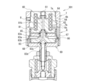
- FIG. 7 is a vertical sectional view showing the upper part of a valve device according to a fourth embodiment of the present invention.
- FIG. 1 is a sectional view showing the configuration of a valve device 1 in an open state according to a first embodiment of the present invention.
- FIG. 2 is a sectional view of the valve device 1 of FIG. 1 in a closed state.
- the valve device 1 includes a valve body 2, a valve body 41, a bonnet 5, and a multistage cylinder actuator 60.
- the valve body 2 is made of stainless steel and has an upper surface 2a and side surfaces facing each other.
- a valve chamber 23 having a stepped portion 24 is opened from the upper surface 2a, and an inner circumferential screw portion 25 to be screwed into the bonnet 5 is formed.
- the valve body 2 forms a first flow path 21 and a second flow path 22.
- the first flow path 21 is a flow path that opens at the lower surface 2b and the bottom surface of the valve chamber 23.
- the second flow path 22 is a flow path that opens to the lower surface 2b and the side surface of the valve chamber 23.
- the valve body 41 is a member that shuts off and communicates with the first flow path 21 and the second flow path 22 by coming into contact with and separating from the valve seat 48 .
- a seat flat structure is adopted in which the flat part around the opening of the first flow path 21 is used as the valve seat 48, and the valve body 41 is a substantially disk-shaped valve body made of heat-resistant resin.
- an annular protrusion for sealing is provided on the periphery of the surface that contacts the valve seat 48.
- the valve body 41 is attached to a bellows mechanism (42, 43, 44) and is held movable in the vertical direction, so that it can come into contact with and separate from the valve seat 48.
- This bellows mechanism includes a substantially rod-shaped stem 44 that has a valve body holding part 44a that holds the valve body 41 at the lower end and extends upward, and an outer circumference that fits into the inner circumferential surface of the upper part of the valve chamber 23.
- a support ring 43 whose lower surface abuts the stepped portion 24 and whose inner circumference guides the stem 44 movably in the vertical direction, and a support ring 43 that is airtightly or liquid-tightly welded to the lower surface of the support ring 43 and the upper surface of the valve body holding portion 44a of the stem 44.
- the bellows 42 has a substantially cylindrical shape and surrounds the rod-shaped portion of the stem 44.
- the bellows 42 is made of spring steel or the like and has many folds so that it can expand and contract in the vertical direction.
- a sealing member 43a is provided at the corner between the lower surface and the outer peripheral surface of the support ring 43 to seal the space between the support ring 43 and the valve body 2.
- the upper end portion of the stem 44 projects upward from the support ring 43 and forms a threaded rod portion 44c.
- This bellows mechanism (42, 43, 44) holds the valve body 41 movably in the vertical direction, and also controls the opening of the first passage 21 and the second passage 22 in the valve chamber 23. It is integrally sealed from the outside to enhance the leakage prevention effect of non-controlled fluid.
- valve body 41 and its support mechanism are not limited to this configuration, and for example, a diaphragm may be used, thereby realizing the movable function of the valve body and the sealing function of the valve chamber.
- a bellows mechanism is advantageous in terms of the maximum opening degree and durability of the valve.
- the bonnet 5 is a substantially cylindrical bag-like member with an open lower end, and an outer peripheral threaded portion 5c is formed at the lower end, and is screwed into an inner peripheral threaded portion 25 of the valve body 2. Thereby, the bonnet 5 is fixed to the valve body 2, and the support ring 43 is pressed and fixed to the valve body 2 via the presser ring 45.
- a substantially stepped cylindrical connecting member 46 having screw holes provided coaxially from the upper and lower sides is provided so as to be slidable in the vertical direction.
- a threaded rod portion 44c at the upper end of the stem 44 is screwed into the lower threaded hole of the connecting member 46, and an outer circumferential threaded portion at the lower end of the operating shaft 83d of the lower piston 83, which will be described later, is inserted into the upper threaded hole. are screwed together, thereby connecting the stem 44 and the operating shaft 83d of the lower piston 83.
- a lower spring 47 made of a coil spring, which will be described later, is also arranged inside the bonnet 5 and urges the connecting member 46 downward.
- the multistage cylinder actuator 60 is an actuator that brings the valve body 41 into contact with and away from the valve seat, and includes a casing (6, 69), an upper piston 81, and a lower piston 83.
- the casing (6, 69) is a cylindrical container whose both ends in the vertical direction are closed by an upper end plate 6a and a lower end plate 69a, respectively, and whose interior is divided into an upper cylinder chamber 64 and a lower cylinder chamber 66 by a partition plate 82. .
- the casing is made up of an upper casing 6 and a lower casing 69 screwed together.
- the lower casing 69 is integrally formed with a cylindrical portion 69b, a lower end plate 69a, and a lower protruding tube portion 69c, and an outer circumferential threaded portion 69d provided on the lower protruding tube portion 69c is connected to the upper end plate portion of the bonnet 5.
- the lower end of the lower protruding tube portion 69c serves as an upper limit stopper for the movable range of the connecting member 46, and its vertical position can be adjusted by screwing into the through-screw hole 5b of the bonnet 5.
- the maximum separation amount of the valve body 41 connected to the connecting member 46 via the stem 44 from the valve seat 48 that is, the maximum opening degree (Cv value) of the valve device 1 can be adjusted.
- the upper casing 6 is formed by integrally forming a cylindrical portion 6b and an upper end plate 6a, and an inner peripheral threaded portion 6c formed at the lower end of the cylindrical portion 6b is connected to an outer peripheral threaded portion 6c formed at the cylindrical portion 69b of the lower casing 69. It is screwed into the threaded portion 69e. At that time, the outer edge portion of the partition plate (bulkhead) 82 is sandwiched and fixed between the upper end portion of the lower casing 69 and the inner circumferential stepped portion of the cylindrical portion 6b, and the inside of the casing (6, 69) is separated from the upper cylinder chamber 64 and the lower step. It is divided into a cylinder chamber 66.
- the upper end plate 6a of the upper casing 6 is provided with an operation air introduction hole 61 passing through it, and the cylindrical portion 6b is provided with a ventilation hole 62 leading to the non-pressure chamber portion of the upper cylinder chamber 64 and A vent hole 67 is provided to the non-pressure chamber portion of the cylinder chamber 66.
- the upper piston 81 is slidably disposed within the upper cylinder chamber 64 and is biased downward by an upper spring 63 made of a coil spring, and is pushed into the upper pressure chamber 65 formed between the upper cylinder chamber 64 and the partition plate 82. This is a member that is driven upward by the pressure of the operating air.
- An O-ring 91 is provided on the outer periphery of the upper piston 81 so that it can slide on the inner periphery of the casing 6 while maintaining airtightness.
- an O-ring 93 is also arranged between the outer periphery of the protruding pipe portion 81e that further protrudes from the upper end of the upper piston 81 and the inner periphery of the operating air introduction hole 61 that penetrates the upper end plate 6a of the casing 6.
- the protruding tube portion 81e can be moved while maintaining airtightness.
- the lower piston 83 is slidably disposed within the lower cylinder chamber 66, is biased downward by the lower spring 47 disposed within the bonnet 5, and is formed between the lower end plate 69a and the lower end plate 69a. This is a member that is driven upward by the pressure of operating air in the lower pressure chamber 68.
- An O-ring 91 is provided on the outer periphery of the lower piston 83 so that it can slide on the inner periphery of the casing 6 while maintaining airtightness.
- the lower piston 83 has an operating shaft 83d that projects downward.
- the operation shaft 83d protrudes by passing through the center hole of the lower end plate 69a of the lower casing 69 and the inside of the lower protruding tube portion 69c, and the outer circumferential threaded portion formed at the tip portion is connected to the connecting member 46 as described above. It is screwed into the upper screw hole. Thereby, the operating shaft 83d is coupled to the stem 44, and can operate the position of the valve body 41 attached to the lower end thereof.
- An O-ring 91 is also arranged between the outer periphery of the operating shaft 83d and the inner periphery of the center hole of the lower end plate 69a of the lower casing 69, so that the operating shaft 83d can slide while maintaining airtightness. It has become.
- the lower piston 83 also has an abutment shaft 83a that projects upward.
- the contact shaft 83a passes through the partition plate 82, fits into a fitting hole 81d of the upper piston 81, and contacts the upper piston 81 at the inner part of the fitting hole 81d.
- An O-ring 91 is also arranged between the outer periphery of the abutment shaft 83a and the inner periphery of the central hole of the partition plate 82, so that the abutment shaft 83a can slide while maintaining airtightness. There is.
- the upper piston 81 has an upper operating air passage 81b inside.
- the upper operation air passage 81b includes a main passage 81b extending from the upper end of the protruding pipe part 81e provided on the upper protruding part 81a of the upper piston 81 on the internal central axis, and a main passage 81b extending from the main passage 81b in a top view. It has a plurality of branch flow paths 81c that branch radially and open at the lower surface of the upper piston 81 facing the upper pressure chamber 65, respectively. Thereby, operating air can be introduced from the operating air introduction hole 61 of the upper casing 6 and supplied to the upper stage pressure chamber 65 and the lower stage piston 83.
- the number of branch channels 81c is preferably three or more, thereby making it possible to equalize the pressure in the pressure receiving area of the piston, suppressing the tilting movement of the piston at the time of starting, and increasing the operating speed.
- the lower piston 83 has a lower operation air passage 83b therein.
- the lower operation air passage 83b opens at the tip of the abutting shaft 83a and extends along the central axis, and radially branches from the main flow passage 83b when viewed from above, and faces the lower pressure chamber 68.
- the lower piston 83 has a plurality of branch flow passages 83c each opening at the lower surface of the lower piston 83. Thereby, operating air from the upper operating air passage 81b can be introduced at the contact portion with the upper piston 81, and the operating air can be supplied to the lower pressure chamber 68.
- the number of branch channels 83c is preferably three or more, thereby making it possible to equalize the pressure in the pressure receiving area of the piston, suppressing the tilting movement of the piston at the time of starting, and increasing the operating speed.
- a reduced diameter portion is provided at the tip of the contact shaft 83a of the lower piston 83, and an O-ring 92 is disposed between the outer periphery of this reduced diameter portion and the inner periphery of the fitting hole of the upper piston 81. .
- This O-ring 92 prevents leakage of operating air while allowing relative displacement between the upper piston and the abutting shaft.
- a known material can be used, such as fluororubber, silicone rubber, or nitrile rubber. Thereby, it is possible to prevent an imbalance between the operating pressures of the upper piston and the lower piston due to leakage of operating air, and it is possible to increase the operating speed while ensuring ease of manufacture.
- the capacities of the upper pressure chamber 65 and the lower pressure chamber 68 are designed to be as small as possible when the valve is fully closed. are doing.
- the operation of the valve device of this embodiment configured as described above will be explained.
- the upper pressure chamber 65 and the lower pressure chamber 68 have no thrust. Therefore, the upper piston 81 receives the urging force R1 of the upper spring 63 and presses the lower piston 83 downward. Under the biasing force R2, the valve body 41 is pressed against the valve seat 48, and the valve is in a fully closed state.
- the operating air When the operating air is supplied from an external control solenoid valve (not shown) to the operating air introduction hole 61, it is introduced from the upper end of the protruding pipe portion 81e of the upper piston 81 into the main flow path 81b of the upper operating air passage 81b. be done. A part of it is supplied to the upper pressure chamber 65 through a plurality of branch channels 81c that branch radially from the main channel 81b. The other part of the operating air is introduced into the main flow path 83b of the lower operating air passage 83b from the tip of the contact shaft 83a of the lower piston 83 fitted in the fitting hole 81d, and is further introduced into the main flow path 83b of the lower operating air passage 83b.
- the rise of the lower piston 83 tends to be delayed and the valve opening time tends to be longer.
- the O-ring 92 is provided at the contact portion to prevent leakage of operating air, the pressure in the lower pressure chamber 68 can be increased more quickly, the lower piston 83 can be raised more quickly, and the valve can be opened. It can save time.
- the upper limit position of the lower piston 83 is determined by the Cv adjustment mechanism, that is, the contact between the upper end of the connecting member 46 and the lower end of the lower protruding pipe portion 69c of the lower casing 69;
- the upper limit position of the piston 81 is determined by the contact between the upper piston 81 and the ceiling of the casing 6 .
- the operating air is transferred from the upper pressure chamber 65 and the lower pressure chamber 68 to the upper operating air passage 81b and the lower operating air. It is exhausted through passage 83b.
- the pressures in the upper pressure chamber 65 and the lower pressure chamber 68 decrease, and the thrusts of F1 and F2 decrease, respectively, so the upper piston 81 moves downward under the urging force R1 of the upper spring 63, and the lower piston 83 is lowered by the biasing force R2 of the lower spring 47.
- the valve body 41 is brought into contact with the valve seat 48 and the valve is closed.
- the flow of operating air from the lower pressure chamber 68 far from the operating air introduction hole 61 to the main channels 83b and 81b is prevented, and the pressure drop in the lower pressure chamber 68 is delayed from the pressure drop in the upper pressure chamber 65. There was a tendency. As a result, the downward movement of the lower piston 83 was delayed and the valve closing time tended to be longer.
- the O-ring 92 is provided at the contact part to prevent leakage of operating air, the pressure in the lower pressure chamber 68 can be lowered more quickly, the lower piston 83 can be raised more quickly, and the valve can be opened. It can save time.
- each operating air passage is branched radially from a main passage (81b, 83b) provided on the central axis within each piston (81, 83), and from the main passage (81b, 83b).
- the pressure of the pistons (81, 83) can be made uniform, and the tilting motion of the pistons (81, 83) at the time of starting can be suppressed, thereby increasing the operating speed.
- FIG. 3 is a graph showing an example of the relationship between the operating time and operating air pressure of the valve device of this embodiment and the conventional valve device, where (a) shows the valve opening time and (b) shows the valve closing time.
- the conventional valve device is a valve device in which the O-ring 92 is not provided at the contact portion between the upper piston and the lower piston.
- the valve opening time is the time from receiving a command to open the valve until it actually becomes open
- the valve closing time is the time from receiving a command to close the valve until it actually becomes closed.
- the valve device of this embodiment is shorter in both the valve opening time and the valve closing time by 2 to 3 msec at each operating pressure than the conventional valve device.
- FIG. 4 is a vertical sectional view showing the upper part of the valve device 101 according to the second embodiment of the present invention.
- the lower part of this valve device is the same as that in FIG. 1, so illustration is omitted.
- the lower stage side of the multi-stage cylinder actuator 60 has a two-stage structure, resulting in a total of three-stage cylinder structure.
- the lower cylinder chamber (66) is divided from the upper side into a first lower cylinder chamber 66_1 and a second lower cylinder chamber 66_2 by a second partition plate 84.
- This second partition plate 84 has the same form as the partition plate 82 and has sealing O-rings 91 on the outer circumferential side and the inner circumferential side.
- the casing 6 further includes an intermediate casing 70 between the upper casing 6 and the lower casing 69, an inner threaded portion of the lower part of the intermediate casing 70 is screwed into an outer threaded portion of the lower casing 69, and the lower end of the upper casing 6
- the inner circumferential threaded portions of the intermediate casing 70 are connected to each other by screwing into the outer circumferential threaded portions of the upper portion of the intermediate casing 70.
- the outer edge of the partition plate 82 is sandwiched and fixed between the upper end of the intermediate casing 70 and the inner step of the upper casing 6, and the outer edge of the second partition plate 84 is sandwiched between the upper end of the lower casing 69 and the middle. It is sandwiched and fixed between the inner circumferential step portion of the casing 70.
- the lower piston (83) includes a first lower piston 83_1 arranged in the first lower cylinder chamber 66_1 and a second lower piston 83_2 arranged in the second lower cylinder chamber 66_2.
- the second lower piston 83_2 has an upper protrusion 83_2a having an outer circumferential thread at its tip, and this upper protrusion 83_2a passes through the center through hole of the second partition plate 84 and is connected to the first lower piston. It is screwed into the screw hole 83_1.
- the first lower piston 83_1 and the second lower piston 83_2 are fixedly connected through the second partition plate 84 and are provided so as to be integrally slidable.
- the lower pressure chamber (68) is a first lower pressure chamber 68_1 formed between the first lower piston 83_1 and the second partition plate 84, and a lower pressure chamber 68_1 formed between the second lower piston 83_2 and the lower end plate 69a.
- a second lower pressure chamber 68_2 is formed.
- the operating shaft 83d is provided on the second lower piston 83_2, and the contact shaft 83a is provided on the first lower piston 83_1.
- the intermediate casing 70 is provided with a ventilation hole 71 leading to the non-pressure chamber portion of the second lower cylinder chamber 66_2.
- the main flow path 83b of the lower operation air passage 83b extends on the central axis of the first lower piston 83_1 and the second lower piston 83_2 that are coupled to each other, and from this main flow path 83b, a plurality of branch flow paths 83c are formed. They are branched radially in a top view and open at the lower surface of the first lower piston 83_1 facing the first lower pressure chamber 68_1. In addition, a plurality of branch channels 83c branch radially from a further downstream portion of the main channel 83b in a top view, and open on the lower surface of the second lower piston 83_2 facing the second lower pressure chamber 68_2. ing.
- valve device 101 of the second embodiment configured in this way is similar to the operation of the valve device 1 of the first embodiment.
- the driving force of the piston can be increased.
- FIG. 5 is a vertical sectional view showing the upper part of a valve device 201 according to a third embodiment of the present invention.
- the lower part of this valve device is the same as that in FIG. 1, so illustration is omitted.
- the upper stage side of the multistage cylinder actuator 60 has a two-stage structure, resulting in a total of three-stage cylinder structure.
- the upper cylinder chamber (64) is divided from the bottom into a first upper cylinder chamber 64_1 and a second upper cylinder chamber 64_2 by a third partition plate 85.
- This third partition plate 85 has the same form as the partition plate 82 and has sealing O-rings 91 on the outer circumferential side and the inner circumferential side.
- the casing 6 further includes an intermediate casing 70 between the upper casing 6 and the lower casing 69, an inner threaded portion of the lower part of the intermediate casing 70 is screwed into an outer threaded portion of the lower casing 69, and the lower end of the upper casing 6
- the inner circumferential threaded portions of the intermediate casing 70 are connected to each other by screwing into the outer circumferential threaded portions of the upper portion of the intermediate casing 70.
- the partition plate 82 has its outer edge sandwiched between the upper end of the lower casing 69 and the inner step of the intermediate casing 70 and is fixed, and the third partition plate 85 has its outer edge sandwiched between the upper end of the intermediate casing 70 and the upper part. It is sandwiched and fixed between the inner circumferential step portion of the casing 6.
- the upper piston (81) includes a first upper piston 81_1 disposed within the first upper cylinder chamber 64_1 and a second upper piston 81_2 disposed within the second upper cylinder chamber 64_2.
- the first upper stage piston 81_1 has an upper protruding part 81_1a having an outer circumferential threaded part at its tip, and this upper protruding part 81_1a passes through the central through hole of the third partition plate 85 and is connected to the second upper stage piston. It is screwed into the screw hole 81_2. Thereby, the first upper stage piston 81_1 and the second upper stage piston 81_2 are fixedly connected through the third partition plate 85 and are provided so as to be integrally slidable.
- the upper pressure chamber (65) includes a first upper pressure chamber 65_1 formed between the first upper piston 81_1 and the partition plate 82 and a space between the second upper piston 81_2 and the third partition plate 85.
- the second upper stage pressure chamber 65_2 is formed.
- the protruding pipe portion 81e is provided at the upper end portion of the second upper stage piston 81_2.
- the intermediate casing 70 is provided with a vent hole 71 leading to the non-pressure chamber portion of the lower cylinder chamber 66.
- the main flow path 81b of the upper operation air passage 81b extends on the central axis of the first upper piston 81_1 and the second upper piston 81_2 that are coupled to each other, and from this main flow path 81b, a plurality of branch flow paths 83c are formed.
- the pistons branch radially in a top view, and open at the lower surface of the first upper piston 81_1 facing the first upper pressure chamber 65_1.
- a plurality of branch channels 83c branch radially from a further downstream portion of the main channel 81b in a top view, and open on the lower surface of the second upper stage piston 81_2 facing the second upper stage pressure chamber 65_2. ing.
- valve device 201 of the third embodiment configured in this way is similar to the operation of the valve device 1 of the first embodiment. However, since the cylinder has a total of three stages, the driving force of the piston can be increased.
- FIG. 6 is a vertical sectional view showing the upper part of a valve device 301 according to a fourth embodiment of the present invention.
- the lower part of the present valve device 301 is the same as that in FIG. 1, so illustration thereof is omitted.
- the lower piston 83 is used instead of the branch flow path 81c (see FIG. 1) that opens on the lower surface of the upper piston 81 as a passage for supplying operating air to the upper pressure chamber 65 in the first embodiment.
- a horizontal branch flow path 83e opening on the outer circumferential surface of the contact shaft 83a is provided.
- This embodiment also includes a cover member 7 that is screwed onto the outer periphery of the upper casing 6, and a vent hole 62 to the non-pressure chamber portion of the upper cylinder chamber 64 and a vent hole to the non-pressure chamber portion of the lower cylinder chamber 66.
- the opening degree of each of the openings 67 can be adjusted.
- the upper operation air passage 81b provided in the upper piston 81 has only a main flow passage 81b extending on the central axis of the upper piston 81, and a branch flow passage 81c (see FIG. 1). ) does not have.
- the upper operating air passage main flow passage 81b
- a lower operation air passage 83b provided in the lower piston 83 opens at the tip of the abutment shaft 83a, and branches into a main passage 83b extending along the central axis and radially from this main passage 83b when viewed from above.
- a plurality of branch passages 83c open on the lower surface of the lower piston 83 facing the lower pressure chamber 68, and a plurality of branch passages 83c that branch radially from the main passage 83b in the abutment shaft 83a when viewed from above, and abutment. It has a plurality of horizontal branch channels 83e that open on the outer peripheral surface of the shaft 83a.
- the branch passage 81c (see FIG. 1) that opens on the lower surface of the upper piston 81 is omitted, but in the first embodiment, this branch passage 81c is maintained.
- the plurality of branch channels 83c that open on the lower surface of the lower piston 83 may be omitted.
- a passage (not shown) similar to the horizontal branch passage 83e may be provided in the operation shaft 83d of the lower piston 83 instead, and the operation air from the main passage 83b may be passed through this passage to the lower pressure chamber 68. may be supplied to
- a cover member 7 that is screwed onto the outer periphery of the upper casing 6 is also provided to provide ventilation holes 62 to the non-pressure chamber portion of the upper cylinder chamber 64 and communication to the non-pressure chamber portion of the lower cylinder chamber 66.
- the opening degree of each of the pores 67 can be adjusted.
- the outer diameter of the upper part of the cylindrical part 6b is smaller than that of the lower end, and an outer peripheral threaded part 6d is formed at the upper part of the outer peripheral surface of this reduced diameter part. ing.
- the cover member 7 formed in a cylindrical shape fits into the outer circumference of the cylindrical portion 6b having a reduced diameter, and the inner circumferential threaded portion 7a formed on the inner circumferential surface of the cover member 7 is connected to the outer circumferential threaded portion of the upper casing 6. It is screwed onto 6d. By rotating the cover member 7, the cover member 7 is moved in the vertical direction with respect to the upper casing 6.
- the vent hole 67 communicating with the non-pressure chamber portion of the lower cylinder chamber 66 is bent upward within the wall of the cylindrical portion 6b and opens at the stepped surface 6e of the cylindrical portion 6b.
- the vent hole 67 communicating with the non-pressure chamber portion of the upper cylinder chamber 64 opens at the outer peripheral surface immediately above the stepped surface 6e of the cylindrical portion 6b.
- the cover member 7 When the cover member 7 is at the lower limit position of the movable range, the lower end surface of the lower end portion 7b of the cover member 7 abuts the step surface 6e of the cylindrical portion 6b to close the opening of the ventilation hole 67, and the lower end surface of the lower end portion 7b of the cover member 7 The inner peripheral surface closes the opening of the ventilation hole 62.
- the cover member 7 By rotating the cover member 7 and adjusting its vertical position, the degree of opening of each of the ventilation holes 67 and 62 by the lower end portion 7b can be adjusted.
- the adjusted position of the cover member 7 can be fixed with a lock screw 8 provided on the cover member 7.
- valve device 301 of the fourth embodiment configured in this way is similar to the operation of the valve device 1 of the first embodiment.
- the branch passage 81c that opens on the lower surface of the upper piston 81 is omitted and the horizontal branch passage 83e that opens on the outer peripheral surface of the contact shaft 83a of the lower piston 83 is provided, the same effect as in the first embodiment can be obtained. It is possible to facilitate manufacturing while maintaining the same.
- the opening degrees of the vent holes 62 to the non-pressure chamber portion of the upper cylinder chamber 64 and the vent holes 67 to the non-pressure chamber portion of the lower cylinder chamber 66 can be adjusted, thereby reducing the load of opening and closing the valves. It is possible to adjust the valve opening time and the valve closing time to almost match each other.
- Valve device 2 Valve body 2a Upper surface 2b Lower surface 5 Bonnet 5a Upper end plate portion 5b Penetrating screw hole 5c Peripheral threaded portion 6 Upper casing (casing) 6a Upper end plate 6b Cylindrical portion 6c Inner circumference threaded portion 6d Outer circumference threaded portion 7 Cover member 7a Inner circumference threaded portion 7b Lower end portion 8 Lock screw 21 First passage 22 Second passage 23 Valve chamber 24 Step portion 25 Inner circumference Threaded portion 41 Valve body 42 Bellows 43 Support ring 43a Seal member 44 Stem 44a Valve body holding portion 44c Threaded rod portion 45 Holding ring 46 Connection member 47 Lower spring 48 Valve seat 51 Fixing nut 60 Multi-stage cylinder actuator 61 Operation air introduction hole 62 Open Air hole 63 Upper spring 64 Upper cylinder chamber 64_1 First upper cylinder chamber 64_2 Second upper cylinder chamber 65 Upper pressure chamber 65_1 First upper pressure chamber 65_2 Second upper pressure chamber 66 Lower cylinder chamber 66_1 First lower cylinder Chamber 66
Landscapes
- Engineering & Computer Science (AREA)
- General Engineering & Computer Science (AREA)
- Mechanical Engineering (AREA)
- Fluid-Driven Valves (AREA)
Abstract
Description
このエア駆動式のバルブ装置は、エアシリンダアクチュエータを用いて、弁体の弁座への押しつけ及び離間を行う形式で、エアシリンダ機構の駆動は、外部の電磁弁で制御された操作エアの供給とその解除により行われている。
バルブ開動作の高速化のためにエアシリンダの駆動力の強化が要求される一方、集積ガスシステムへの搭載の観点からバルブ装置の幅寸法の小型化が要求されているので、このために多段シリンダアクチュエータがバルブ開閉アクチュエータとして採用されている。
また、上段ピストンと下段ピストンを分離した構造では、上段ピストンと下段ピストンの当接箇所から操作エアがリークして、複数のシリンダ室の圧力のばらつきとそれに起因するバルブ開閉動作の遅延が生ずることが懸念されている。
前記第1の流路の開口部に水平に設けられた弁座に対して当接及び離間することにより、前記第1の流路と前記第2の流路との間を遮断及び連通させる弁体と、
前記弁体を、前記弁座に対して当接及び離間させる多段シリンダアクチュエータと、
を備えるバルブ装置であって、
前記多段シリンダアクチュエータは、
前記バルブボディから上方向に伸びて、両端部がそれぞれ上端板と下端板で閉塞され、内部が仕切板で上段シリンダ室及び下段シリンダ室に区分された円筒状のケーシングと、
前記上段シリンダ室内に摺動可能に配置され、上段バネによって下方向に付勢されるとともに、前記仕切板との間に形成される上段圧力室内の操作エアの圧力で上方向に駆動される上段ピストンと、
前記下段シリンダ室内に摺動可能に配置され、下段バネによって下方向に付勢されるとともに、前記下端板との間に形成される下段圧力室内の操作エアの圧力で上方向に駆動され、前記下端板を貫いて突出し前記弁体の位置を操作する操作軸及び、前記仕切板を貫いて突出し前記上段ピストンに当接する当接軸とを有する下段ピストンと、
を有し、
前記上段ピストンは、外部から操作エアを導入して前記上段圧力室及び前記下段圧力室に当該操作エアを供給する上段操作エア通路を内部に有し、
前記下段ピストンは、前記上段ピストンと前記当接軸との当接部分で前記上段操作エア通路に連通して操作エアを導入し前記下段圧力室に当該操作エアを供給する下段操作エア通路を内部に有し、
前記当接部分には、前記上段ピストンと前記当接軸との間の相対的な変位を許容しつつ操作エアの漏れを防ぐOリングが設けられていることを特徴とする。
前記上段操作エア通路及び前記下段操作エア通路の少なくとも一方は、前記メイン流路から上面視で放射状に分岐して、前記上段圧力室に面する前記上段ピストンの下面又は前記下段圧力室に面する前記下段ピストンの下面に開口する複数の分岐流路をさらに有する、構成を好ましく採用できる。
前記下段ピストンは、前記第1の下段シリンダ室内に配置された第1の下段ピストンと、前記第2の下段シリンダ室内に配置された第2の下段ピストンとからなり、当該第1の下段ピストン及び第2の下段ピストンは、前記第2の仕切板を貫いて固定的に接続されて一体的に摺動可能に設けられ、
前記下段圧力室は、前記第1の下段ピストンと前記第2の仕切板との間に形成される第1の下段圧力室及び前記第2の下段ピストンと前記下端板との間に形成される第2の下段圧力室からなり、
前記操作軸は前記第2の下段ピストンに設けられ、前記当接軸は前記第1の下段ピストンに設けられた、構成としてもよい。
前記上段ピストンは、前記第1の上段シリンダ室内に配置された第1の上段ピストンと、前記第2の上段シリンダ室内に配置された第2の上段ピストンとからなり、当該第1の上段ピストン及び第2の上段ピストンは、前記第3の仕切板を貫いて固定的に接続されて一体的に摺動可能に設けられ、
前記上段圧力室は、前記第1の上段ピストンと前記仕切板との間に形成される第1の上段圧力室及び前記第2の上段ピストンと前記第3の仕切板との間に形成される第2の上段圧力室からなる、
構成としてもよい。
(第1の実施形態)
図1は、本発明の第1の実施形態に係る開状態におけるバルブ装置1の構成を示す断面図である。図2は、図1のバルブ装置1における、閉状態を示す断面図である。図1に示すように、バルブ装置1は、バルブボディ2と、弁体41と、ボンネット5と、多段シリンダアクチュエータ60とを有する。
また、弁体41は、ベローズ機構(42、43,44)に取付けられて上下方向に可動に保持され、バルブシート48に対して当接及び離間できるようになっている。このベローズ機構は、下端部に弁体41を保持する弁体保持部44aを有して上方向に伸びる略ロッド状のステム44と、外周が弁室23上部の内周面に嵌合するとともに下面が段差部24に当接し、内周がステム44を上下方向に移動可能に案内する支持リング43と、支持リング43の下面及びステム44の弁体保持部44a上面に気密又は液密に溶接されてステム44のロッド状部分を包囲する略円筒状のベローズ42からなる。ベローズ42は、バネ鋼等で形成され、多数のひだを有して上下方向に伸縮できるようになっている。尚、支持リング43の下面と外周面とのコーナーにはシール部材43aが設けられ、バルブボディ2との間を封止している。また、ステム44の上端部分は、支持リング43から上側に突出し、ネジ棒部分44cを形成している。
このベローズ機構(42、43,44)は、弁体41を上下方向に可動に保持するとともに、弁室23における前記第1の流路21の開口部及び第2の流路22の開口部を一体的に外部から封止し、非制御流体の漏れ防止効果を高めている。
本発明において、弁体41とその支持機構はこの構成に限られず、例えばダイヤフラムを用いてもよく、これにより、弁体としての可動機能と弁室の封止機能も実現できる。但し、ベローズ機構を用いると弁の最大開度及び耐久性の点では有利である。
ボンネット5の内部には、上側と下側から同軸にネジ孔が設けられた略段付円柱状の接続部材46が、上下方向に摺動可能に設けられている。この接続部材46の下側のネジ孔には前記ステム44の上端部のネジ棒部分44cが螺合され、上側のネジ孔には、後述する下段ピストン83の操作軸83d下端部の外周ネジ部が螺合され、これによりステム44と下段ピストン83の操作軸83dを接続している。
ボンネット5の内部には、また、後述するコイルバネからなる下段バネ47が配置され、接続部材46を下方向に付勢している。
下部ケーシング69は、円筒部分69bと下端板69aと下側突出管部69cが一体的に形成されてなり、下側突出管部69cに設けられた外周ネジ部69dは、ボンネット5の上端板部分5aに穿設された貫通ネジ穴5bに螺合し、固定ナット51で固定されている。
尚、下側突出管部69cの下端部は、接続部材46の可動域の上限ストッパーになっており、ボンネット5の貫通ネジ穴5bへの螺合調整により上下位置調整が可能になっている。これにより、接続部材46にステム44を介して接続された弁体41のバルブシート48に対する最大離間量、すなわち、バルブ装置1の最大開度(Cv値)を調整できる。
なお、上部ケーシング6の上端板6aには、これを貫通する操作エア導入孔61が設けられており、円筒部分6bには、上段シリンダ室64の非圧力室部分への通気孔62及び、下段シリンダ室66の非圧力室部分への通気孔67が設けられている。
下段ピストン83は、下方向に突出する操作軸83dを有する。この操作軸83dは、下部ケーシング69の下端板69aの中央孔及び下側突出管部69cの内側を通過して突出し、先端部に形成された外周ネジ部が、前記のように、接続部材46の上側ネジ穴に螺合している。これにより、操作軸83dは、ステム44に結合され、その下端部に取付けられた弁体41の位置を操作できるようになっている。尚、操作軸83dの外周と、下部ケーシング69の下端板69aの中央孔の内周との間にも、Oリング91が配置され、操作軸83dが気密性を維持しつつ摺動できるようになっている。
下段ピストン83は、また上方に突出する当接軸83aを有する。この当接軸83aは、仕切板82を貫いて、上段ピストン81の嵌合孔81dに嵌合し、この嵌合孔81dの奥部で上段ピストン81に当接している。尚、当接軸83aの外周と、仕切板82の中央孔の内周との間にも、Oリング91が配置され、当接軸83aが気密性を維持しつつ摺動できるようになっている。
尚、操作エアの流入・流出時間を短くしてバルブ装置1の動作速度を高速化するために、バルブ全閉状態における上段圧力室65及び下段圧力室68の容量は、なるべく小さくなるように設計している。
まず、操作エアが操作エア導入孔61に供給されないときは、上段圧力室65及び下段圧力室68は、推力を有さない。このため、上段ピストン81は、上段バネ63の付勢力R1を受けて、下段ピストン83を下方向に押圧するとともに、下段ピストン83は、上段ピストン81の押圧力(=R1)及び下段バネ47の付勢力R2を受けて、弁体41をバルブシート48に押圧してバルブは全閉状態にある。
これにより、上段圧力室65及び下段圧力室68の圧力が上昇し、図2に示すようにそれぞれF1,F2の推力を発生させるので、先ず、上段バネ63の付勢力R1のみを受けている上段ピストン81が、差分F1-R1の力を受けて上昇する。その結果、下段ピストン83は、上段ピストン81の押圧力(=R1)から解放されて下段バネ47の付勢力R2に抗して、差分F2-R2の力を受けて上昇し、接続部材46上端が、下部ケーシング69の下側突出管部69c下端に当接して止まる。これにより、弁体41をバルブシート48から離間させてバルブが全開になる。
従来構造では、上段ピストン81と下段ピストン83の当接部にOリングがなく、ここから操作エアが漏れて上段圧力室65に流入し、操作エア導入孔61から遠い下段圧力室68に届きにくかったので、下段圧力室68の圧力上昇は、上段圧力室65の圧力上昇より遅れる傾向があった。その結果、下段ピストン83の上昇が遅れて弁開時間が掛かる傾向があった。本発明のバルブ装置では、当接部分にOリング92を設けて操作エアの漏れを防いだので、下段圧力室68の圧力上昇を早めることができ、下段ピストン83の上昇を早めて、弁開時間を短縮できる。
これにより、上段圧力室65及び下段圧力室68の圧力が低下し、それぞれF1,F2の推力が減少するので、上段ピストン81が、上段バネ63の付勢力R1を受けて下降するとともに、下段ピストン83が、下段バネ47の付勢力R2を受けて下降する。それにより、弁体41をバルブシート48当接させてバルブを閉じる。
従来構造では、上段ピストン81と下段ピストン83の当接部にOリング92がなく、上段圧力室65の操作エアが、分岐流路83c以外に、ここからもメイン流路81bに流出してしまうため、操作エア導入孔61から遠い下段圧力室68からは、メイン流路83b、81bへの操作エアの流出が妨げられて、下段圧力室68の圧力下降が上段圧力室65の圧力下降より遅れる傾向があった。その結果、下段ピストン83の下降が遅れて弁閉時間が掛かる傾向があった。本発明のバルブ装置では、当接部にOリング92を設けて操作エアの漏れを防いだので、下段圧力室68の圧力下降を早めることができ、下段ピストン83の上昇を早めて、弁開時間を短縮できる。
図4は、本発明の第2の実施形態のバルブ装置101の上部を示す縦断面図である。
本バルブ装置の下部は、図1と同じなので、図示を省略する。
本実施形態は、第1の実施形態において、多段シリンダアクチュエータ60の下段側を2段構造とし、合計3段シリンダ構成としたものである。
下段圧力室(68)は、第1の下段ピストン83_1と第2の仕切板84との間に形成される第1の下段圧力室68_1及び第2の下段ピストン83_2と下端板69aとの間に形成される第2の下段圧力室68_2からなる。また、操作軸83dは第2の下段ピストン83_2に設けられ、当接軸83aは第1の下段ピストン83_1に設けられている。尚、中間ケーシング70には、第2の下段シリンダ室66_2の非圧力室部分への通気孔71が設けられている。
このように構成された第2の実施形態のバルブ装置101の動作は、第1の実施形態のバルブ装置1の動作と同様である。但し、合計3段シリンダ構成としたので、ピストンの駆動力を増強することができる。
図5は、本発明の第3の実施形態のバルブ装置201の上部を示す縦断面図である。
本バルブ装置の下部は、図1と同じなので、図示を省略する。
本実施形態は、第1の実施形態において、多段シリンダアクチュエータ60の上段側を2段構造とし、合計3段シリンダ構成としたものである。
上段圧力室(65)は、第1の上段ピストン81_1と仕切板82との間に形成される第1の上段圧力室65_1及び第2の上段ピストン81_2と第3の仕切板85との間に形成される第2の上段圧力室65_2からなる。また、突出管部81eは、第2の上段ピストン81_2の上端部に設けられている。尚、中間ケーシング70には、下段シリンダ室66の非圧力室部分への通気孔71が設けられている。
図6は、本発明の第4の実施形態のバルブ装置301の上部を示す縦断面図である。
本バルブ装置301の下部は、図1と同じなので、図示を省略する。
本実施形態は、第1の実施形態において、上段圧力室65へ操作エアを供給するための通路として、上段ピストン81下面に開口する分岐流路81c(図1参照)の代わりに、下段ピストン83の当接軸83a外周面に開口する水平分岐流路83eを設けたものである。本実施形態は、また上部ケーシング6の外周に螺合するカバー部材7を設け、上段シリンダ室64の非圧力室部分への通気孔62及び、下段シリンダ室66の非圧力室部分への通気孔67のそれぞれの開度を調整できるようにしたものである。
図6に示す上部ケーシング6は、円筒部分6bの上部側の外径が下端側よりも縮径しており、この縮径された部分の外周面の上部には、外周ネジ部6dが形成されている。円筒状に形成されたカバー部材7は、上記縮径した円筒部分6bの外周に嵌合するとともに、カバー部材7の内周面に形成された内周ネジ部7aが上部ケーシング6の外周ネジ部6dに螺合している。カバー部材7を回転させることにより、カバー部材7が上部ケーシング6に対して上下方向に移動するようになっている。
下段シリンダ室66の非圧力室部分に連通する通気孔67は、円筒部分6bの壁内部で上方に屈曲し、円筒部分6bの段差面6eに開口している。一方、上段シリンダ室64の非圧力室部分に連通する通気孔67は、円筒部分6bの段差面6eの直ぐ上の外周面で開口している。
このように構成された第4の実施形態のバルブ装置301の動作は、第1の実施形態のバルブ装置1の動作と同様である。但し、上段ピストン81下面に開口する分岐流路81cを省略して、下段ピストン83の当接軸83a外周面に開口する水平分岐流路83eを設けたので、第1の実施形態と同様の効果を維持しつつ、製造の容易化を図ることができる。
また、上段シリンダ室64の非圧力室部分への通気孔62及び、下段シリンダ室66の非圧力室部分への通気孔67のそれぞれの開度を調整できるようにしたので、弁開閉の負荷を調整でき、弁開時間と弁閉時間とをほぼ一致させることが可能となる。
2 バルブボディ
2a 上面
2b 下面
5 ボンネット
5a 上端板部分
5b 貫通ネジ穴
5c 外周ネジ部
6 上部ケーシング(ケーシング)
6a 上端板
6b 円筒部分
6c 内周ネジ部
6d 外周ネジ部
7 カバー部材
7a 内周ネジ部
7b 下端部
8 ロックねじ
21 第1の流路
22 第2の流路
23 弁室
24 段差部
25 内周ネジ部
41 弁体
42 ベローズ
43 支持リング
43a シール部材
44 ステム
44a 弁体保持部
44c ネジ棒部分
45 押えリング
46 接続部材
47 下段バネ
48 バルブシート
51 固定ナット
60 多段シリンダアクチュエータ
61 操作エア導入孔
62 通気孔
63 上段バネ
64 上段シリンダ室
64_1 第1の上段シリンダ室
64_2 第2の上段シリンダ室
65 上段圧力室
65_1 第1の上段圧力室
65_2 第2の上段圧力室
66 下段シリンダ室
66_1 第1の下段シリンダ室
66_2 第2の下段シリンダ室
67 通気孔
68 下段圧力室
68_1 第1の下段圧力室
68_2 第2の下段圧力室
69 下部ケーシング
69a 下端板
69b 円筒部分
69c 下側突出管部
69d 外周ネジ部
69e 外周ネジ部
70 中間ケーシング
71 通気孔
81 上段ピストン
81a 上方突出部
81b メイン流路(上段操作エア通路)
81c 分岐流路
81d 嵌合孔
81e 突出管部
81_1 第1の上段ピストン
81_1a上方突出部
81_2 第2の上段ピストン
82 仕切板
83 下段ピストン
83a 当接軸
83b メイン流路(下段操作エア通路)
83c 分岐流路
83d 操作軸
83e 水平分岐流路
83_1 第1の下段ピストン
83_2 第2の下段ピストン
83_2a 上方突出部
84 第2の仕切板
85 第3の仕切板
91,92,93 Oリング
101,201,301 バルブ装置
F1,F2 推力
R1,R2 付勢力
Claims (7)
- 第1の流路及び第2の流路が内部に形成されたバルブボディと、
前記第1の流路の開口部に水平に設けられた弁座に対して当接及び離間することにより、前記第1の流路と前記第2の流路との間を遮断及び連通させる弁体と、
前記弁体を、前記弁座に対して当接及び離間させる多段シリンダアクチュエータと、
を備えるバルブ装置であって、
前記多段シリンダアクチュエータは、
前記バルブボディから上方向に伸びて、両端部がそれぞれ上端板と下端板で閉塞され、内部が仕切板で上段シリンダ室及び下段シリンダ室に区分された円筒状のケーシングと、
前記上段シリンダ室内に摺動可能に配置され、上段バネによって下方向に付勢されるとともに、前記仕切板との間に形成される上段圧力室内の操作エアの圧力で上方向に駆動される上段ピストンと、
前記下段シリンダ室内に摺動可能に配置され、下段バネによって下方向に付勢されるとともに、前記下端板との間に形成される下段圧力室内の操作エアの圧力で上方向に駆動され、前記下端板を貫いて突出し前記弁体の位置を操作する操作軸及び、前記仕切板を貫いて突出し前記上段ピストンに当接する当接軸とを有する下段ピストンと、
を有し、
前記上段ピストンは、外部から操作エアを導入して前記上段圧力室及び前記下段圧力室に当該操作エアを供給する上段操作エア通路を内部に有し、
前記下段ピストンは、前記上段ピストンと前記当接軸との当接部分で前記上段操作エア通路に連通して操作エアを導入し前記下段圧力室に当該操作エアを供給する下段操作エア通路を内部に有し、
前記当接部分には、前記上段ピストンと前記当接軸との間の相対的な変位を許容しつつ操作エアの漏れを防ぐOリングが設けられていることを特徴とする、
バルブ装置。 - 前記上段ピストンは、前記下段ピストンの前記当接軸と嵌合する嵌合孔を有し、前記当接部分は前記当接軸の先端部と前記嵌合孔の奥部に形成され、前記Oリングは、前記当接軸の先端部に設けられた縮径部の外周と、前記嵌合孔の内周の間に配置されている、請求項1に記載のバルブ装置。
- 前記上段操作エア通路は、前記上段ピストン内の中心軸上に設けられたメイン流路を備え、前記下段操作エア通路は、前記下段ピストン内の中心軸上に設けられたメイン流路を備え、
前記上段操作エア通路及び前記下段操作エア通路の少なくとも一方は、前記メイン流路から上面視で放射状に分岐して、前記上段圧力室に面する前記上段ピストンの下面又は前記下段圧力室に面する前記下段ピストンの下面にそれぞれ開口する複数の分岐流路をさらに有する請求項1又は2に記載のバルブ装置。 - 前記上段操作エア通路が前記分岐流路を有する場合、当該分岐流路の本数は3以上であり、前記下段操作エア通路が前記分岐流路を有する場合、当該分岐流路の本数は3以上である、請求項3に記載のバルブ装置。
- 前記ケーシングは、前記下段シリンダ室を上側から第1の下段シリンダ室と第2の下段シリンダ室に区分する第2の仕切板をさらに有し、
前記下段ピストンは、前記第1の下段シリンダ室内に配置された第1の下段ピストンと、前記第2の下段シリンダ室内に配置された第2の下段ピストンとからなり、当該第1の下段ピストン及び第2の下段ピストンは、前記第2の仕切板を貫いて固定的に接続されて一体的に摺動可能に設けられ、
前記下段圧力室は、前記第1の下段ピストンと前記第2の仕切板との間に形成される第1の下段圧力室及び前記第2の下段ピストンと前記下端板との間に形成される第2の下段圧力室からなり、
前記操作軸は前記第2の下段ピストンに設けられ、前記当接軸は前記第1の下段ピストンに設けられた、請求項1に記載のバルブ装置。 - 前記ケーシングは、前記上段シリンダ室を下側から第1の上段シリンダ室と第2の上段シリンダ室に区分する第3の仕切板をさらに有し、
前記上段ピストンは、前記第1の上段シリンダ室内に配置された第1の上段ピストンと、前記第2の上段シリンダ室内に配置された第2の上段ピストンとからなり、当該第1の上段ピストン及び第2の上段ピストンは、前記第3の仕切板を貫いて固定的に接続されて一体的に摺動可能に設けられ、
前記上段圧力室は、前記第1の上段ピストンと前記仕切板との間に形成される第1の上段圧力室及び前記第2の上段ピストンと前記第3の仕切板との間に形成される第2の上段圧力室からなる、
請求項1に記載のバルブ装置。 - 前記弁体は、当該弁体の上下方向の動きを許容しつつ前記第1の流路の開口部及び前記第2の流路の開口部を一体的に外部から封止する、ベローズを含む支持機構に取付けられている、請求項1に記載のバルブ装置。
Priority Applications (3)
| Application Number | Priority Date | Filing Date | Title |
|---|---|---|---|
| JP2024511441A JP7741590B2 (ja) | 2022-03-30 | 2023-02-21 | バルブ装置 |
| US18/718,204 US20250129863A1 (en) | 2022-03-30 | 2023-02-21 | Valve device |
| KR1020247024795A KR102938169B1 (ko) | 2022-03-30 | 2023-02-21 | 밸브 장치 |
Applications Claiming Priority (2)
| Application Number | Priority Date | Filing Date | Title |
|---|---|---|---|
| JP2022055475 | 2022-03-30 | ||
| JP2022-055475 | 2022-03-30 |
Publications (1)
| Publication Number | Publication Date |
|---|---|
| WO2023189013A1 true WO2023189013A1 (ja) | 2023-10-05 |
Family
ID=88200446
Family Applications (1)
| Application Number | Title | Priority Date | Filing Date |
|---|---|---|---|
| PCT/JP2023/006122 Ceased WO2023189013A1 (ja) | 2022-03-30 | 2023-02-21 | バルブ装置 |
Country Status (5)
| Country | Link |
|---|---|
| US (1) | US20250129863A1 (ja) |
| JP (1) | JP7741590B2 (ja) |
| KR (1) | KR102938169B1 (ja) |
| TW (1) | TWI848637B (ja) |
| WO (1) | WO2023189013A1 (ja) |
Families Citing this family (1)
| Publication number | Priority date | Publication date | Assignee | Title |
|---|---|---|---|---|
| KR102883884B1 (ko) | 2024-11-29 | 2025-11-10 | 주식회사 아스플로 | 윤활유 비산 방지 구조를 갖는 공압 액추에이터 및 이를 포함하는 밸브 장치 |
Citations (2)
| Publication number | Priority date | Publication date | Assignee | Title |
|---|---|---|---|---|
| JP2009002524A (ja) * | 2008-10-03 | 2009-01-08 | Fujikin Inc | 流体制御器用多段アクチュエータおよびこれを備えた流体制御器 |
| JP2020020371A (ja) * | 2018-07-31 | 2020-02-06 | 株式会社フジキン | アクチュエータおよびこれを用いたバルブ装置 |
Family Cites Families (8)
| Publication number | Priority date | Publication date | Assignee | Title |
|---|---|---|---|---|
| JP3691012B2 (ja) | 2001-11-26 | 2005-08-31 | 東京瓦斯株式会社 | 整圧装置 |
| KR20090002524A (ko) | 2007-06-30 | 2009-01-09 | 주식회사 한빛티앤아이 | 스윙 타입 개폐 구조 및 이 구조를 사용한 멀티미디어 장치 |
| JP2010025171A (ja) | 2008-07-16 | 2010-02-04 | Asahi Organic Chem Ind Co Ltd | 吐出制御器 |
| JP5810446B2 (ja) | 2012-02-24 | 2015-11-11 | 株式会社アドヴィックス | ダイヤフラム装置 |
| JP7187011B2 (ja) | 2018-09-07 | 2022-12-12 | 株式会社フジキン | アクチュエータ、バルブ、流体供給システム、および半導体製造装置 |
| JP7296739B2 (ja) | 2019-01-31 | 2023-06-23 | 東京エレクトロン株式会社 | 処理装置及び処理装置の動作方法 |
| JP7061587B2 (ja) | 2019-04-05 | 2022-04-28 | Ckd株式会社 | 流体制御弁 |
| JP7382054B2 (ja) | 2019-08-29 | 2023-11-16 | 株式会社フジキン | バルブ装置および流量制御装置 |
-
2023
- 2023-02-21 WO PCT/JP2023/006122 patent/WO2023189013A1/ja not_active Ceased
- 2023-02-21 US US18/718,204 patent/US20250129863A1/en active Pending
- 2023-02-21 JP JP2024511441A patent/JP7741590B2/ja active Active
- 2023-02-21 KR KR1020247024795A patent/KR102938169B1/ko active Active
- 2023-03-27 TW TW112111461A patent/TWI848637B/zh active
Patent Citations (2)
| Publication number | Priority date | Publication date | Assignee | Title |
|---|---|---|---|---|
| JP2009002524A (ja) * | 2008-10-03 | 2009-01-08 | Fujikin Inc | 流体制御器用多段アクチュエータおよびこれを備えた流体制御器 |
| JP2020020371A (ja) * | 2018-07-31 | 2020-02-06 | 株式会社フジキン | アクチュエータおよびこれを用いたバルブ装置 |
Also Published As
| Publication number | Publication date |
|---|---|
| KR102938169B1 (ko) | 2026-03-12 |
| JP7741590B2 (ja) | 2025-09-18 |
| JPWO2023189013A1 (ja) | 2023-10-05 |
| KR20240116965A (ko) | 2024-07-30 |
| US20250129863A1 (en) | 2025-04-24 |
| TW202346744A (zh) | 2023-12-01 |
| TWI848637B (zh) | 2024-07-11 |
Similar Documents
| Publication | Publication Date | Title |
|---|---|---|
| JP5049296B2 (ja) | ドームロード型圧力調整器 | |
| KR102468504B1 (ko) | 메탈 다이어프램 밸브 | |
| JPWO2020021911A1 (ja) | バルブ装置、流体制御装置、流体制御方法、半導体製造装置及び半導体製造方法 | |
| EP3614025B1 (en) | Two-way valve | |
| WO2023189013A1 (ja) | バルブ装置 | |
| JP3300686B2 (ja) | 多段ピストンアクチュエータ | |
| CA2619394C (en) | Solenoid isolation valve | |
| US11261990B2 (en) | Actuator and valve device | |
| WO2017047359A1 (ja) | ソレノイドバルブ | |
| JP7187011B2 (ja) | アクチュエータ、バルブ、流体供給システム、および半導体製造装置 | |
| JP7148989B2 (ja) | アクチュエータ、バルブ、流体供給システム、および半導体製造装置 | |
| WO2020246316A1 (ja) | 減衰力調整式緩衝器 | |
| JP7636037B2 (ja) | バルブ装置 | |
| WO2023032576A1 (ja) | 圧力補償弁 | |
| JP6433228B2 (ja) | 空気レギュレータ | |
| JP7246075B2 (ja) | 膨張弁 | |
| JP7365147B2 (ja) | 高温バルブ用小径アクチュエータと高温バルブ | |
| JP2025086864A (ja) | バルブ開閉速度低減ユニット及びバルブ装置 | |
| JP2002364770A (ja) | 流体制御弁 | |
| JP6741415B2 (ja) | 圧力調整器 | |
| KR20190025102A (ko) | 레귤레이터 | |
| JP2025157768A (ja) | 流体制御弁 | |
| WO2018073945A1 (ja) | 気体混合器 | |
| JP2023082494A (ja) | 整圧装置 | |
| JP2025034646A (ja) | 膨張弁 |
Legal Events
| Date | Code | Title | Description |
|---|---|---|---|
| 121 | Ep: the epo has been informed by wipo that ep was designated in this application |
Ref document number: 23779043 Country of ref document: EP Kind code of ref document: A1 |
|
| ENP | Entry into the national phase |
Ref document number: 20247024795 Country of ref document: KR Kind code of ref document: A |
|
| ENP | Entry into the national phase |
Ref document number: 2024511441 Country of ref document: JP Kind code of ref document: A |
|
| NENP | Non-entry into the national phase |
Ref country code: DE |
|
| 122 | Ep: pct application non-entry in european phase |
Ref document number: 23779043 Country of ref document: EP Kind code of ref document: A1 |
|
| WWP | Wipo information: published in national office |
Ref document number: 18718204 Country of ref document: US |