WO2023188917A1 - 両回転式スクロール型圧縮機 - Google Patents
両回転式スクロール型圧縮機 Download PDFInfo
- Publication number
- WO2023188917A1 WO2023188917A1 PCT/JP2023/005061 JP2023005061W WO2023188917A1 WO 2023188917 A1 WO2023188917 A1 WO 2023188917A1 JP 2023005061 W JP2023005061 W JP 2023005061W WO 2023188917 A1 WO2023188917 A1 WO 2023188917A1
- Authority
- WO
- WIPO (PCT)
- Prior art keywords
- scroll
- driven
- driving
- drive
- housing
- Prior art date
- Legal status (The legal status is an assumption and is not a legal conclusion. Google has not performed a legal analysis and makes no representation as to the accuracy of the status listed.)
- Ceased
Links
Images




Classifications
-
- F—MECHANICAL ENGINEERING; LIGHTING; HEATING; WEAPONS; BLASTING
- F04—POSITIVE - DISPLACEMENT MACHINES FOR LIQUIDS; PUMPS FOR LIQUIDS OR ELASTIC FLUIDS
- F04C—ROTARY-PISTON, OR OSCILLATING-PISTON, POSITIVE-DISPLACEMENT MACHINES FOR LIQUIDS; ROTARY-PISTON, OR OSCILLATING-PISTON, POSITIVE-DISPLACEMENT PUMPS
- F04C18/00—Rotary-piston pumps specially adapted for elastic fluids
- F04C18/02—Rotary-piston pumps specially adapted for elastic fluids of arcuate-engagement type, i.e. with circular translatory movement of co-operating members, each member having the same number of teeth or tooth-equivalents
- F04C18/0207—Rotary-piston pumps specially adapted for elastic fluids of arcuate-engagement type, i.e. with circular translatory movement of co-operating members, each member having the same number of teeth or tooth-equivalents both members having co-operating elements in spiral form
- F04C18/023—Rotary-piston pumps specially adapted for elastic fluids of arcuate-engagement type, i.e. with circular translatory movement of co-operating members, each member having the same number of teeth or tooth-equivalents both members having co-operating elements in spiral form where both members are moving
-
- F—MECHANICAL ENGINEERING; LIGHTING; HEATING; WEAPONS; BLASTING
- F04—POSITIVE - DISPLACEMENT MACHINES FOR LIQUIDS; PUMPS FOR LIQUIDS OR ELASTIC FLUIDS
- F04C—ROTARY-PISTON, OR OSCILLATING-PISTON, POSITIVE-DISPLACEMENT MACHINES FOR LIQUIDS; ROTARY-PISTON, OR OSCILLATING-PISTON, POSITIVE-DISPLACEMENT PUMPS
- F04C18/00—Rotary-piston pumps specially adapted for elastic fluids
- F04C18/02—Rotary-piston pumps specially adapted for elastic fluids of arcuate-engagement type, i.e. with circular translatory movement of co-operating members, each member having the same number of teeth or tooth-equivalents
- F04C18/0207—Rotary-piston pumps specially adapted for elastic fluids of arcuate-engagement type, i.e. with circular translatory movement of co-operating members, each member having the same number of teeth or tooth-equivalents both members having co-operating elements in spiral form
- F04C18/0246—Details concerning the involute wraps or their base, e.g. geometry
- F04C18/0269—Details concerning the involute wraps
-
- F—MECHANICAL ENGINEERING; LIGHTING; HEATING; WEAPONS; BLASTING
- F04—POSITIVE - DISPLACEMENT MACHINES FOR LIQUIDS; PUMPS FOR LIQUIDS OR ELASTIC FLUIDS
- F04C—ROTARY-PISTON, OR OSCILLATING-PISTON, POSITIVE-DISPLACEMENT MACHINES FOR LIQUIDS; ROTARY-PISTON, OR OSCILLATING-PISTON, POSITIVE-DISPLACEMENT PUMPS
- F04C23/00—Combinations of two or more pumps, each being of rotary-piston or oscillating-piston type, specially adapted for elastic fluids; Pumping installations specially adapted for elastic fluids; Multi-stage pumps specially adapted for elastic fluids
- F04C23/008—Hermetic pumps
-
- F—MECHANICAL ENGINEERING; LIGHTING; HEATING; WEAPONS; BLASTING
- F04—POSITIVE - DISPLACEMENT MACHINES FOR LIQUIDS; PUMPS FOR LIQUIDS OR ELASTIC FLUIDS
- F04C—ROTARY-PISTON, OR OSCILLATING-PISTON, POSITIVE-DISPLACEMENT MACHINES FOR LIQUIDS; ROTARY-PISTON, OR OSCILLATING-PISTON, POSITIVE-DISPLACEMENT PUMPS
- F04C2240/00—Components
- F04C2240/30—Casings or housings
-
- F—MECHANICAL ENGINEERING; LIGHTING; HEATING; WEAPONS; BLASTING
- F04—POSITIVE - DISPLACEMENT MACHINES FOR LIQUIDS; PUMPS FOR LIQUIDS OR ELASTIC FLUIDS
- F04C—ROTARY-PISTON, OR OSCILLATING-PISTON, POSITIVE-DISPLACEMENT MACHINES FOR LIQUIDS; ROTARY-PISTON, OR OSCILLATING-PISTON, POSITIVE-DISPLACEMENT PUMPS
- F04C2240/00—Components
- F04C2240/40—Electric motor
-
- F—MECHANICAL ENGINEERING; LIGHTING; HEATING; WEAPONS; BLASTING
- F04—POSITIVE - DISPLACEMENT MACHINES FOR LIQUIDS; PUMPS FOR LIQUIDS OR ELASTIC FLUIDS
- F04C—ROTARY-PISTON, OR OSCILLATING-PISTON, POSITIVE-DISPLACEMENT MACHINES FOR LIQUIDS; ROTARY-PISTON, OR OSCILLATING-PISTON, POSITIVE-DISPLACEMENT PUMPS
- F04C2240/00—Components
- F04C2240/80—Other components
- F04C2240/808—Electronic circuits (e.g. inverters) installed inside the machine
Definitions
- the present invention relates to a dual rotary scroll compressor.
- Patent Document 1 discloses a conventional double-rotating scroll compressor (hereinafter simply referred to as a compressor).
- This compressor includes a drive mechanism, a drive scroll, a driven mechanism, a driven scroll, and a cylindrical housing.
- the drive mechanism has an electric motor provided within the housing.
- the drive scroll is provided within the housing and is rotationally driven around the drive axis by a drive mechanism.
- the driven scroll is provided within the housing, and is driven to rotate around the driven axis by the driving scroll and the driven mechanism while being eccentric with respect to the driving scroll.
- the drive scroll has a drive end plate and a drive spiral body.
- the drive end plate extends in a direction intersecting the drive axis.
- the drive spiral body protrudes from the drive end plate toward the driven scroll and has a spiral shape.
- the driven scroll has a driven end plate and a driven spiral body.
- the driven end plate extends in a direction intersecting the driven axis.
- the driven scroll body projects from the driven end plate toward the drive scroll and has a spiral shape.
- the driving scroll and the driven scroll face each other to form a compression chamber, and the volume of the compression chamber is changed by rotational driving and rotational driving.
- a compression load is generated by compressing the refrigerant within the compression chamber.
- This compressive load mainly acts in the radial direction of the drive shaft rather than in the drive shaft direction. Therefore, the compressive load in the radial direction of the drive shaft acts on the housing via the bearings that pivotally support the drive scroll and the driven scroll, which may cause the housing to vibrate.
- vibration of the housing caused by such a compressive load is not considered a problem. If the inverter circuit that drives the electric motor is installed on the outer circumferential surface of the housing to prevent the compressor from increasing in size in the direction of the drive shaft, the vibration of the housing will cause the inverter circuit and the thin shape that accommodates the inverter board to The noise may also be exacerbated by the noise being amplified by the casing.
- the present invention has been made in view of the above-mentioned conventional situation, and provides an inverter circuit on the outer circumferential surface of the housing, while reducing vibration and noise generated due to compressive loads acting in the radial direction of the drive shaft center.
- the problem to be solved is to provide a double-rotating scroll type compressor that can reduce the
- the double rotary scroll type compressor of the present invention includes a drive mechanism, a drive scroll, a driven mechanism, a driven scroll, and a cylindrical housing
- the drive scroll is provided within the housing and is rotationally driven around a drive axis by the drive mechanism
- the driven scroll is provided in the housing, and is rotated by the driving scroll and the driven mechanism around a driven axis while being eccentric with respect to the driving scroll
- the driving scroll has a driving end plate extending in a direction intersecting the driving axis, and a driving spiral body projecting from the driving end plate toward the driven scroll and forming a spiral shape
- the driven scroll has a driven end plate extending in a direction intersecting the driven axis, and a driven spiral body projecting from the driven end plate toward the driving scroll and forming a spiral shape
- the driving scroll and the driven scroll face each other, the driving scroll and the driven scroll form a compression chamber, and the rotational driving and the rotational driving cause the driving scroll and the driven scroll to reduce the volume of the compression chamber.
- the drive mechanism includes an electric motor provided in the housing, and an inverter circuit provided on the outer peripheral surface of the housing to drive the electric motor, In a virtual plane perpendicular to the drive axis, The midpoint between the center of the driving-side base circle forming the driving spiral body and the center of the driven-side base circle forming the driven spiral body is determined by the rotation of the driving scroll and the driven scroll to determine the diameter of the drive shaft center.
- the direction perpendicular to the virtual line connecting the two contact points is defined as the load direction of the compressive load, and
- the inverter circuit is arranged so as to avoid the variation range in the circumferential direction of the drive shaft center.
- the refrigerant is compressed within the compression chamber, thereby generating a compression load that mainly acts in the radial direction of the drive shaft center.
- compressive load acts in the radial direction of the rotating shaft that orbits the orbiting scroll.
- the direction of the compressive load acting in the radial direction of this rotating shaft changes by 360 degrees as the orbiting scroll rotates.
- compressive load means compressive load that acts in the radial direction of the drive shaft center or the radial direction of the rotating shaft.
- the driving scroll and the driven scroll rotate at the same angular velocity while being eccentric. Therefore, the direction of the compressive load does not change significantly in the circumferential direction of the drive shaft during operation of the compressor. That is, the range of compressive load generated during operation of the compressor is limited to a predetermined small angular range in the circumferential direction of the drive shaft center.
- the present inventors focused on this point and completed the present invention.
- the inverter circuit provided on the outer peripheral surface of the housing is arranged in the circumferential direction of the drive shaft, avoiding the fluctuation range defined above. . Therefore, it is possible to suppress the vibration of the housing caused by the compressive load from being amplified by the thin casing that houses the inverter circuit and the inverter board, and as a result, it is also possible to suppress the noise from worsening.
- the double-rotating scroll compressor of the present invention is capable of suppressing vibration and noise generated due to the compressive load acting in the radial direction of the drive shaft center, while providing an inverter circuit on the outer peripheral surface of the housing. .
- the electric motor has a stator fixed to a housing, and a rotor disposed within the stator and rotatable together with a drive scroll, the drive scroll being built into the rotor, and the inverter circuit being disposed around the outer periphery of the stator. is preferred.
- the inverter circuit will be placed around the outer periphery of the drive scroll. If the drive scroll and inverter circuit are arranged in the radial direction of the drive shaft center, the influence of the compressive load acting on the drive scroll and driven scroll will be transmitted to the housing and the inverter installed on its outer circumferential surface via the bearings that support them. Easy to reach the circuit. For this reason, the problem that vibrations of the housing are amplified by the inverter circuit becomes particularly noticeable, but this problem can be effectively solved by the present invention.
- the inverter circuit is arranged around the outer periphery of the stator, it is advantageous to simplify the wiring structure for feeding power from the inverter circuit to the stator.
- the stator, rotor, and inverter circuit are arranged in the radial direction of the drive shaft center with respect to the drive scroll and the driven scroll. For this reason, the compressor can be made smaller in the drive shaft direction compared to the case where the stator, rotor, and inverter circuit are lined up in the drive shaft direction with respect to the drive scroll and the driven scroll.
- the double-rotating scroll compressor of the present invention is capable of suppressing vibrations and noise generated due to compressive loads acting in the radial direction of the drive shaft center, while providing an inverter circuit on the outer peripheral surface of the housing.
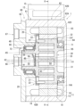
- FIG. 1 is a schematic sectional view showing a cross section of a portion other than an inverter case of a double rotary scroll compressor according to an embodiment.
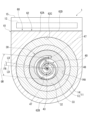
- FIG. 2 is a sectional view taken along line II-II in FIG. 1.
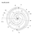
- FIG. 3 is a schematic diagram illustrating the direction of the compression load in the double-rotating scroll compressor of the embodiment, and shows the moment when the compression chamber formed on the outermost side is closed (at the time of confinement). It is a diagram.
- FIG. 4 is a schematic diagram illustrating the load direction of the compressive load regarding the dual rotary scroll type compressor of the embodiment, and is a diagram when the compressor is rotated 60 degrees from the time of confinement.
- FIG. 1 is a schematic sectional view showing a cross section of a portion other than an inverter case of a double rotary scroll compressor according to an embodiment.
- FIG. 2 is a sectional view taken along line II-II in FIG. 1.
- FIG. 3 is a schematic diagram illustrating the direction of the compression load
- FIG. 5 is a schematic diagram illustrating the load direction of the compressive load regarding the dual rotary scroll type compressor of the embodiment, and is a diagram when the compressor is rotated 120 degrees from the time of confinement.
- FIG. 6 is a schematic diagram illustrating the load direction of the compressive load regarding the dual rotary scroll type compressor of the embodiment, and is a diagram when the compressor is rotated 180 degrees from the time of confinement.
- FIG. 7 is a schematic diagram illustrating the load direction of the compressive load regarding the dual rotary scroll type compressor of the embodiment, and is a diagram when the compressor is rotated 240 degrees from the time of confinement.
- FIG. 6 is a schematic diagram illustrating the load direction of the compressive load regarding the dual rotary scroll type compressor of the embodiment, and is a diagram when the compressor is rotated 120 degrees from the time of confinement.
- FIG. 7 is a schematic diagram illustrating the load direction of the compressive load regarding the dual rotary scroll type compressor of the embodiment, and is a diagram when the compressor is rotated 240 degrees from
- FIG. 8 is a schematic diagram illustrating the load direction of the compressive load regarding the dual rotary scroll type compressor of the embodiment, and is a diagram when the compressor is rotated 300 degrees from the time of confinement.
- FIG. 9 is a schematic diagram illustrating the load direction of the compressive load regarding the dual rotary scroll type compressor of the embodiment, and is a diagram immediately before the compressor rotates 360 degrees from the time of confinement.
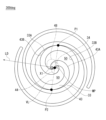
- FIG. 10 is a schematic diagram illustrating the variation range of the compressive load in the load direction regarding the double rotary scroll type compressor of the embodiment.
- FIG. 11 is a schematic diagram illustrating the range in which compressive loads occur in the double rotary scroll compressor of the embodiment.
- a dual rotary scroll compressor 1 (hereinafter simply referred to as compressor 1) of the embodiment is an example of a specific embodiment of the present invention.
- the compressor 1 includes a housing 60.
- the housing 60 has a housing body 61 and a cover 65.
- the housing body 61 is a bottomed cylindrical member having an outer peripheral wall 62 and a bottom wall 63.
- the outer peripheral wall 62 has a cylindrical inner peripheral surface 62C centered on the drive axis X1.
- the bottom wall 63 extends in a substantially circular plate shape orthogonal to the drive axis X1.
- the outer peripheral edge of the bottom wall 63 is connected to the base end of the outer peripheral wall 62 that is remote from the cover 65.
- a cylindrical shaft support 64 centered on the drive shaft center X1 is provided in a protruding manner.
- An outer ring of a bearing 71 is fitted into the shaft support 64 .
- the cover 65 extends in a substantially circular plate shape orthogonal to the drive axis X1.
- the cover 65 closes the housing body 61 by being fastened to the outer peripheral wall 62 with bolts (not shown) with its outer peripheral edge abutting the tip of the outer peripheral wall 62 of the housing body 61.
- a cylindrical shaft support 66 centered on the driven shaft center X2 is provided at the center of the inner surface of the cover 65.
- the driven shaft center X2 extends parallel to the drive shaft center X1 while being eccentric by a predetermined eccentric amount with respect to the drive shaft center X1.
- An outer ring of a needle bearing 72 is fitted into the shaft support 66 .
- the cover 65 has a suction hole 67 and a discharge hole 68.
- the suction hole 67 is located between the outer peripheral edge of the cover 65 and the shaft support 66, and passes through the cover 65 in a direction parallel to the drive axis X1.
- the discharge hole 68 is located at the center of the cover 65 and passes through the cover 65 in a direction parallel to the drive axis X1.
- the compressor 1 includes a drive mechanism 10, a driven mechanism 20, a drive scroll 30, and a driven scroll 40.
- the drive mechanism 10 rotates the drive scroll 30 around the drive axis X1.
- the drive mechanism 10 includes an electric motor 11 and an inverter circuit 12 that drives the electric motor 11.
- Electric motor 11 has a stator 13 and a rotor 14.
- the inverter circuit 12 is provided on the outer circumferential surface of the cylindrical housing body 61, that is, on the outer circumferential surface of the outer circumferential wall 62 of the housing 60.
- the inverter circuit 12 is built into an inverter case 15.
- a portion of the outer peripheral wall 62 in a range where the inverter case 15 is attached is a thick wall portion 62A that is thicker than the other thin general portion 62B.
- the outer surface of this thick portion 62A is a flat surface 62D.
- Inverter case 15 is fixed to flat surface 62D with bolts (not shown).
- the inverter substrate constituting the inverter circuit 12 is arranged substantially parallel to the flat surface 62D.
- the inverter case 15 is arranged in a direction in which the drive shaft center X1 and the driven shaft center X2 are lined up in the circumferential direction of the drive shaft center X1 and the driven shaft center X2, that is, the drive shaft center X1 and the driven shaft center X2. It is arranged in a straight line direction connecting the Note that the inverter case 15 is arranged in the direction of a virtual line VL, which will be described later, in the circumferential direction of the drive shaft center X1 and the driven shaft center X2.
- the inverter case 15 avoids the variation range FR of the compressive load in the load direction LD and avoids the compressive load generation range GR in the circumferential direction of the drive shaft center X1 and the driven shaft center X2. It is located.
- the stator 13 has a cylindrical shape centered on the drive axis X1, and has a winding 16.
- the stator 13 is fixed to the housing 60 around the drive axis X1 by fitting into the inner circumferential surface 62C of the outer circumferential wall 62 of the housing body 61.
- the rotor 14 has a cylindrical shape around the drive axis X1.
- the rotor 14 includes a plurality of permanent magnets (not shown) corresponding to the stator 13 and laminated steel plates (not shown) that fix each permanent magnet.
- the rotor 14 is disposed on the inner periphery of the stator 13 and is rotatable within the stator 13 together with the drive scroll 30.
- a drive scroll 30 is built into the rotor 14.
- a drive peripheral wall 32 of the drive scroll 30, which will be described later, is fitted onto the inner peripheral surface 14A of the rotor 14. Thereby, the rotor 14 and the drive scroll 30 rotate together. In this way, the drive scroll 30 is rotationally driven around the drive axis X1 by the drive mechanism 10.
- the drive scroll 30 has a drive end plate 31, a drive peripheral wall 32, and a drive spiral body 33.
- the drive end plate 31 extends in a substantially circular plate shape orthogonal to the drive axis X1. At the center of the surface of the drive end plate 31 that faces the bottom wall 63 of the housing body 61, a cylindrical shafted support 35 is provided in a protruding manner and centered on the drive shaft center X1.
- the inner ring of the bearing 71 is fitted onto the shafted support 35 .
- the drive scroll 30 is provided in the housing 60 so as to be rotatable around the drive axis X1, and is supported by the housing body 61.
- the drive peripheral wall 32 protrudes from the outer circumferential edge 31F of the drive end plate 31 toward the driven scroll 40 in parallel to the drive axis X1, and has a cylindrical shape around the drive axis X1.
- the drive spiral body 33 is located inside the drive peripheral wall 32 in the radial direction of the drive axis X1.
- the drive spiral body 33 protrudes from the drive end plate 31 toward the driven scroll 40 in parallel to the drive axis X1, and has a spiral shape around the drive axis X1.
- the driven scroll 40 has a driven end plate 41 and a driven spiral body 43.
- the driven end plate 41 extends in a substantially circular plate shape orthogonal to the driven axis X2. At the center of the surface of the driven end plate 41 facing the cover 65, a cylindrical shafted support 45 with its center on the driven axis X2 is provided in a protruding manner.
- the inner ring of the needle bearing 72 is fitted onto the shafted support 45 .
- the driven scroll 40 is provided in the housing 60 so as to be rotatable around the driven axis X2, and is supported by the cover 65.
- the driven end plate 41 has a suction port 47 (see FIG. 2) and a discharge port 48.
- the suction port 47 is located outside the outer peripheral surface of the shaft support 66 in the radial direction of the driven axis X2, and passes through the driven end plate 41 in a direction parallel to the driven axis X2.
- Two suction ports 47 are formed on the driven end plate 41 with a phase difference of 180 degrees.
- the discharge port 48 is located radially inward of the driven axis X2 than the inner circumferential surface of the shafted support 45, and passes through the driven end plate 41 in a direction parallel to the driven axis X2.
- a space surrounded by the inner peripheral surface of the shafted support 45 and sandwiched between the cover 65 and the driven end plate 41 is defined as a discharge chamber 55.
- the driven end plate 41 is provided with a discharge valve 58 that is located on the discharge chamber 55 side and opens and closes the discharge port 48, and a retainer 59 that regulates the opening degree of the discharge valve 58.
- the driven spiral body 43 protrudes from the driven end plate 41 toward the drive scroll 30 in parallel to the driven axis X2, and has a spiral shape around the driven axis X2.
- the driving scroll 30 and the driven scroll 40 face each other, and the driving scroll 33 and the driven scroll 43 mesh with each other to form a compression chamber 50.
- the driven mechanism 20 includes multiple sets (three or more sets in the pin-ring system) of pins 21 and rings 22. Each set of pins 21 and rings 22 transmits driving force from the driving scroll 30 to the driven scroll 40.
- Each pin 21 is a cylindrical member that protrudes from the tip of the drive peripheral wall 32 toward the driven end plate 41 at appropriate intervals in the circumferential direction of the drive axis X1.
- Each ring 22 is provided on the driven end plate 41 side so as to face each pin 21.
- Each ring 22 is fitted into a circular bottomed hole formed in the driven end plate 41, respectively.
- Each pin 21 is movable while slidingly contacting the inner peripheral surface of each ring 22.
- each pin 21 slides on the inner peripheral surface of each ring 22 and rotates each ring 22 relatively around the center of each pin 21. By doing so, the torque of the driving scroll 30 is transmitted to the driven scroll 40.
- the turning radius of the ring 22 is made equal to the eccentricity of the driven shaft center X2 of the driven scroll 40 with respect to the drive shaft center X1 of the drive scroll 30.
- the driven scroll 40 is rotated by the drive scroll 30 and the driven mechanism 20 around the driven axis X2 parallel to the drive axis X1 while being eccentric with respect to the drive scroll 30.
- the drive scroll 30 and the driven scroll 40 change the volume of the compression chamber 50 by causing the driven scroll 40 to revolve around the drive axis X1 relative to the drive scroll 30 due to rotational driving and rotational following thereof.
- the compressor 1 constitutes a refrigeration circuit of a vehicle air conditioner together with an evaporator, an expansion valve, and a condenser.
- An evaporator is connected to the suction hole 67 via piping.
- a condenser is connected to the discharge hole 68 via piping.
- the expansion valve is connected to the evaporator and condenser by piping.
- the refrigerant supplied from the evaporator flows into the housing 60 from the suction hole 67 and is introduced into the compression chamber 50 via the suction port 47.
- the refrigerant compressed to the discharge pressure in the compression chamber 50 is discharged to the discharge chamber 55 via the discharge port 48 and discharged from the discharge hole 68 to the condenser. In this way, air conditioning of the vehicle air conditioner is performed.
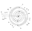
- FIGS. 3 to 11 are diagrams of virtual planes orthogonal to the drive axis X1 and the driven axis X2.
- FIGS. 3 to 9 show the load direction LD of the compression load generated in the compression chamber 50 during approximately one rotation of the driving scroll 30 and the driven scroll 40 during the operation of the compressor 1, in rotation angle increments of 60 degrees. show.
- FIGS. 3 to 11 only the portions of the driving scroll 33 and the driven scroll 43 of the driving scroll 30 and the driven scroll 40 that substantially contribute to the formation of the compression chamber 50 are schematically shown.
- a driving side base circle (base circle of an involute curve) 34 forms an outer surface 33A and an inner surface 33B of the driving spiral body 33, and an outer surface 43A and an inner surface 43B of the driven spiral body 43.
- a driven side base circle (base circle of an involute curve) 44 is shown.
- the circle indicated by the two-dot chain line on the upper side in the figure is the drive-side base circle 34, and the circle indicated by the two-dot chain line on the lower side in the figure is the driven-side base circle 44.
- the center of the drive-side base circle 34 and the center of the driven-side base circle 44 are shifted by a predetermined amount in a direction perpendicular to the drive axis X1.
- the central black circle among the three black circles is the midpoint MP between the center of the drive-side base circle 34 and the center of the driven-side base circle 44.
- the upper one indicates the position of the drive shaft center X1
- the lower one indicates the position of the driven shaft center X2.
- FIGS. 4 to 9 the position of the drive shaft center X1 is shown, but the driven shaft center X2 is omitted.
- FIG. 3 is a diagram at the moment when the two compression chambers 50, 50 on the outermost circumferential side are closed (at the time of closing, 0 deg).
- the outer surface 33A of the driving spiral body 33 and the inner surface 43B of the driven spiral body 43 are in contact with each other at the first contact point P1 on the outermost circumferential side
- the inner surface 33B of the driving spiral body 33 and the outer surface of the driven spiral body 43 are in contact with each other at the first contact point P1.
- 43A is in contact with the second contact point P2 on the outermost circumferential side.
- a virtual line VL is defined that connects the first contact P1 and the second contact P2, which are the two contact points where the driving spiral body 33 and the driven spiral body 43 touch on the outermost side.
- the length of the virtual line VL can be regarded as the radial width of the two compression chambers 50 as a whole.
- the midpoint MP can be regarded as the center of the two compression chambers 50 as a whole.
- a surface that includes the virtual line VL and extends in the axial direction of the drive shaft center X1 and the driven shaft center X2 is defined as a pressure receiving surface of the compressive load.
- the midpoint MP between the center of the driving side base circle 34 and the center of the driven side base circle 44 is defined as the point of application of the compressive load.
- a direction perpendicular to the virtual line VL in a virtual plane perpendicular to the drive axis X1 and the driven axis X2 is defined as a load direction (action direction) LD of the compressive load.
- first contact point P1 is located on one tangent line that touches both the driving side base circle 34 and the driven side base circle 44.
- the second contact point P2 is located on the other tangent line that touches both the driving side base circle 34 and the driven side base circle 44.
- FIG. 4 is a view when rotated 60 degrees from the time of closing.
- FIG. 5 is a view when the device is rotated 120 degrees from the time of closing.
- FIG. 6 is a diagram when the device is rotated 180 degrees from the time of closing.
- FIG. 7 is a diagram when the device is rotated 240 degrees from the time of closing.
- FIG. 8 is a diagram when the device is rotated 300 degrees from the time of closing.
- FIG. 9 is a diagram immediately before rotation of 360 degrees from the time of closing.
- the first contact P1 and the second contact P2 are displaced toward the inner circumferential side.
- the length of the virtual line VL that is, the radial width of the two compression chambers 50 as a whole also gradually decreases.
- the drive shaft center X1 of the drive scroll 30 and the driven shaft center X2 of the driven scroll 40 are eccentric by a predetermined eccentric amount.
- the first contact P1 and the second contact P2 move, so the load direction LD of the compressive load with the midpoint MP as the point of action also changes.
- the range in which the load direction LD fluctuates during one rotation of the driving scroll 30 and the driven scroll 40 is defined as a fluctuation range FR.
- the angle of the load direction LD with respect to the horizontal line is defined as the load angle ⁇ .
- the minimum load angle ⁇ min is reached at the time of closing shown in FIG. 3, and the maximum load angle ⁇ max is reached immediately before rotation by 360 degrees from the time of closing shown in FIG.
- the variation range FR of the load direction LD is the angular range of the difference between the minimum load angle ⁇ min and the maximum load angle ⁇ max.
- the load direction LD at the time of confinement is shown by a solid line arrow, and the load direction LD at the time immediately before rotation of 360 degrees from the time of confinement is shown by a two-dot chain line.
- the compressive load generation range GR is the distance between the first contact P1 and the second contact P2 at the time of closing, that is, the range extending in the load direction LD at this time with a width equal to the length of the virtual line VL. It is defined as
- the inverter case 15 containing the inverter circuit 12 avoids the variation range FR of the load direction LD of the compressive load in the circumferential direction of the drive shaft center X1 and the driven shaft center X2. , and is arranged avoiding the compressive load generation range GR.
- the inverter case 15 provided on the outer circumferential wall 62 of the housing body 61 is configured to change the load direction LD of the compressive load in the circumferential direction of the drive shaft center X1 and the driven shaft center X2. It is placed avoiding range FR.
- the load direction LD of the compressive load whose point of action is the midpoint MP between the center of the driving side base circle 34 and the center of the driven side base circle 44 acts on the outside of the compression chamber 50 at the center of the two compression chambers 50 as a whole. This is the direction of compressive load.
- the distance between the first contact point P1 and the second contact point P2, that is, the length of the virtual line VL, can be regarded as the radial width of the entire two compression chambers.
- the overall size of the two compression chambers 50 is at its maximum when closed.
- the distance between the first contact point P1 and the second contact point P2 at the time of confinement, that is, the length of the virtual line VL can be regarded as the length at which the radial width of the entire two compression chambers 50 is maximized.
- the inverter case has a width equal to the distance between the first contact P1 and the second contact P2 (the length of the virtual line VL) at the time of confinement, and avoids the compressive load generation range GR, which is the range extending in the load direction LD at this time.
- the compressor 1 of the embodiment it is possible to suppress the vibration of the housing 60 caused by the compressive load generated in the compression chamber 50 from being amplified by the inverter circuit 12 and the inverter case 15, and as a result, the noise is worsened. It can also be suppressed.
- the dual rotary scroll type compressor 1 of the embodiment has the inverter circuit 12 provided on the outer circumferential surface of the housing 60, and also reduces the vibration and noise generated due to the compressive load acting in the radial direction of the drive shaft center X1. It can be suppressed.
- a drive scroll 30 and a driven scroll 40 are built into an electric motor 11 provided in a housing 60, and an inverter circuit 12 is installed on the outer periphery of these scrolls, that is, radially outward of the drive shaft center X1.
- An inverter case 15 containing the inverter is arranged.
- the inverter case 15 will be arranged around the outer periphery of the drive scroll 30. If the drive scroll 30 and the inverter case 15 are arranged in the radial direction of the drive shaft center X1, the influence of the compressive load acting on the drive scroll 30 and the driven scroll 40 will be applied to the housing 60 and its outer periphery through the bearings etc. that pivotally support them. It is easy to reach the inverter case 15 and inverter circuit 12 provided on the surface. Therefore, the problem that the vibrations of the housing 60 are amplified by the inverter circuit 12 and the inverter case 15 becomes particularly noticeable, but this compressor 1 can effectively solve this problem.
- the inverter circuit 12 is arranged around the outer periphery of the stator 13, it is advantageous to simplify the wiring structure for feeding power from the inverter circuit 12 to the stator 13.
- the electric motor 11 and the inverter case 15 are arranged in the radial direction of the drive shaft center X1 with respect to the driving scroll 30 and the driven scroll 40, the electric motor 11 and the inverter case 15 are arranged with respect to the driving scroll 30 and the driven scroll 40.
- the compressor 1 can be made smaller in the drive shaft center X1 direction compared to the case where the compressor 1 is arranged in the drive shaft center X1 direction.
- the inverter circuit 12 and the inverter case 15 are arranged in the circumferential direction of the drive shaft center X1 and the driven shaft center X2 in the straight line direction or the virtual line VL direction connecting the drive shaft center X1 and the driven shaft center X2.
- the inverter circuit 12 exists on these straight lines and is arranged so as to be substantially orthogonal to these straight lines, the present invention is not limited to this configuration. That is, in the circumferential direction of the drive shaft center X1, the center of the inverter circuit 12 may be arranged on a straight line or virtual line VL connecting the drive shaft center X1 and the driven shaft center X2.
- the position and angle of the inverter circuit 12 in the circumferential direction of the drive shaft center X1 can be set as appropriate as long as the variation range FR of the load direction LD can be avoided.
- the electric motor 11 and the inverter circuit 12 are arranged in the radial direction of the drive axis X1 with respect to the drive scroll 30 and the driven scroll 40, but the present invention is not limited to this configuration.
- the electric motor 11 may be arranged in the drive axis X1 direction with respect to the drive scroll 30 and the driven scroll 40, and the inverter circuit 12 may be provided on the outer peripheral surface of the housing 60 at the position of the electric motor 11.
- the inverter circuit 12 is provided on the outer peripheral surface of the housing 60 at a position shifted in the drive shaft center X1 direction. You can leave it there.
- the driving spiral body 33 and the driven spiral body 43 have approximately two turns, but the number of turns of the driving spiral body 33 and the driven spiral body 43 is not limited to this.
- the number of compression chambers 50 may be increased by increasing the number of turns of the driving spiral body 33 and the driven spiral body 43.
- the number of windings may be made different between the driving spiral body 33 and the driven spiral body 43. Even in this case, the moment when the two compression chambers 50 are closed on the outermost circumferential side can be defined as the above-mentioned confinement time of 0 degree.
- the minimum load angle ⁇ min was reached at the time of closing, and the maximum load angle ⁇ max was reached just before rotating 360 degrees from the time of closure, but depending on the scroll shape, the minimum load angle ⁇ min In some cases, the time when the load angle ⁇ max reaches the maximum load angle ⁇ max may deviate from the time immediately before the rotation of 360 degrees from the time of closure.
- the driven mechanism 20 is constituted by a pin 21 and a ring 22, but the present invention is not limited to this configuration.
- the driven mechanism 20 uses a pin-ring-pin method in which two pins slide against the inner circumferential surface of one free ring, a pin-pin method in which the outer circumferential surfaces of two pins slide against each other, or an Oldham joint. It may be configured by a method or the like.
- the drive scroll is provided within the housing and is rotationally driven around a drive axis by the drive mechanism
- the driven scroll is provided in the housing, and is rotated by the driving scroll and the driven mechanism around a driven axis while being eccentric with respect to the driving scroll
- the driving scroll has a driving end plate extending in a direction intersecting the driving axis, and a driving spiral body projecting from the driving end plate toward the driven scroll and forming a spiral shape
- the driven scroll has a driven end plate extending in a direction intersecting the driven axis, and a driven spiral body projecting from the driven end plate toward the driving scroll and forming a spiral shape
- the driving scroll and the driven scroll face each other, the driving scroll and the driven scroll form a compression chamber, and the rotational driving and the rotational driving cause the driving scroll and the driven scroll to reduce the volume of the compression chamber.
- the drive mechanism includes an electric motor provided in the housing, and an inverter circuit provided on the outer peripheral surface of the housing to drive the electric motor, In a virtual plane perpendicular to the drive axis, The midpoint between the center of the driving-side base circle forming the driving spiral body and the center of the driven-side base circle forming the driven spiral body is determined by the rotation of the driving scroll and the driven scroll to determine the diameter of the drive shaft center.
- the inverter circuit is arranged in a circumferential direction of the drive shaft center so as to avoid a range extending in the load direction with a width equal to the distance between the first contact point and the second contact point. type scroll compressor.
- the drive scroll is provided within the housing and is rotationally driven around a drive axis by the drive mechanism
- the driven scroll is provided in the housing, and is rotated by the driving scroll and the driven mechanism around a driven axis while being eccentric with respect to the driving scroll
- the driving scroll has a driving end plate extending in a direction intersecting the driving axis, and a driving spiral body projecting from the driving end plate toward the driven scroll and forming a spiral shape
- the driven scroll has a driven end plate extending in a direction intersecting the driven axis, and a driven spiral body projecting from the driven end plate toward the driving scroll and forming a spiral shape
- the driving scroll and the driven scroll face each other, the driving scroll and the driven scroll form a compression chamber, and the rotational driving and the rotational driving cause the driving scroll and the driven scroll to reduce the volume of the compression chamber.
- the drive mechanism includes an electric motor provided in the housing, and an inverter circuit provided on the outer peripheral surface of the housing to drive the electric motor, In a virtual plane perpendicular to the drive axis, When defining a straight line connecting the driving shaft center and the driven shaft center,
- the inverter circuit is a double rotary scroll type compressor, and the inverter circuit is arranged on the straight line in the circumferential direction of the drive shaft center.
- the drive scroll is provided within the housing and is rotationally driven around a drive axis by the drive mechanism
- the driven scroll is provided in the housing, and is rotated by the driving scroll and the driven mechanism around a driven axis while being eccentric with respect to the driving scroll
- the driving scroll has a driving end plate extending in a direction intersecting the driving axis, and a driving spiral body projecting from the driving end plate toward the driven scroll and forming a spiral shape
- the driven scroll has a driven end plate extending in a direction intersecting the driven axis, and a driven spiral body projecting from the driven end plate toward the driving scroll and forming a spiral shape
- the driving scroll and the driven scroll face each other, the driving scroll and the driven scroll form a compression chamber, and the rotational driving and the rotational driving cause the driving scroll and the driven scroll to reduce the volume of the compression chamber.
- the drive mechanism includes an electric motor provided in the housing, and an inverter circuit provided on the outer peripheral surface of the housing to drive the electric motor, In a virtual plane perpendicular to the drive axis, At the moment when the compression chamber formed on the outermost circumferential side is closed, a first contact point where the outer surface of the driving spiral body and the inner surface of the driven spiral body contact on the outermost circumferential side, and the inner surface of the driving spiral body are connected.
- the inverter circuit is a double rotary scroll type compressor, and the inverter circuit is arranged on the virtual line in the circumferential direction of the drive shaft center.
- the present invention can be used, for example, in a vehicle air conditioner.
- Double-rotating scroll compressor 10 Drive mechanism 11 Electric motor 12 Inverter circuit 13 Stator 14 Rotor 20 Driven mechanism 30 Drive scroll 31 Drive end plate 33 Drive spiral body 34 Drive side base circle 40 Driven scroll 41 Driven end plate 43 Drive scroll Body 44 Driven side base circle 50 Compression chamber 60 Housing X1 Drive shaft center X2 Driven shaft center MP Midpoint P1 First contact P2 Second contact VL Virtual line LD Load direction FR Fluctuation range
Landscapes
- Engineering & Computer Science (AREA)
- Mechanical Engineering (AREA)
- General Engineering & Computer Science (AREA)
- Applications Or Details Of Rotary Compressors (AREA)
- Rotary Pumps (AREA)
Abstract
Description
前記駆動スクロールは、前記ハウジング内に設けられるとともに、前記駆動機構によって駆動軸心周りで回転駆動され、
前記従動スクロールは、前記ハウジング内に設けられるとともに、前記駆動スクロールに対して偏心しつつ従動軸心周りで前記駆動スクロール及び前記従動機構によって回転従動され、
前記駆動スクロールは、前記駆動軸心と交差する方向に延びる駆動端板と、前記駆動端板から前記従動スクロールに向かって突出し、渦巻状をなす駆動渦巻体とを有し、
前記従動スクロールは、前記従動軸心と交差する方向に延びる従動端板と、前記従動端板から前記駆動スクロールに向かって突出し、渦巻状をなす従動渦巻体とを有し、
前記駆動スクロール及び前記従動スクロールは互いに対向し、前記駆動渦巻体と前記従動渦巻体とが圧縮室を形成し、前記回転駆動及び前記回転従動によって前記駆動スクロール及び前記従動スクロールは前記圧縮室の容積を変化させる両回転式スクロール型圧縮機において、
前記駆動機構は、前記ハウジング内に設けられた電動モータと、前記ハウジングの外周面に設けられ、前記電動モータを駆動するインバータ回路とを有し、
前記駆動軸心に直交する仮想平面において、
前記駆動渦巻体を形成する駆動側基礎円の中心と、前記従動渦巻体を形成する従動側基礎円の中心との中点を、前記駆動スクロール及び前記従動スクロールの回転により前記駆動軸心の径方向に発生する圧縮荷重の作用点と定義し、
前記駆動渦巻体の外側面と前記従動渦巻体の内側面とが最外周側で接する第1接点と、前記駆動渦巻体の内側面と前記従動渦巻体の外側面とが最外周側で接する第2接点とを結ぶ仮想線に対して直交する方向を、前記圧縮荷重の荷重方向と定義し、かつ、
前記駆動スクロール及び前記従動スクロールが1回転する間に前記荷重方向が変動する範囲を変動範囲と定義したとき、
前記インバータ回路は、前記駆動軸心の周方向において前記変動範囲を避けて配置されていることを特徴とする。
図1に示すように、実施例の両回転式スクロール型圧縮機1(以下、単に圧縮機1という)は、本発明の具体的態様の一例である。圧縮機1は、ハウジング60を備えている。ハウジング60は、ハウジング本体61及びカバー65を有している。
圧縮機1の作動中においては、駆動スクロール30及び従動スクロール40の回転により、圧縮室50内で駆動軸心X1の径方向に圧縮荷重が発生する。
図3に示す閉じ込み時に2つの圧縮室50全体の大きさが最大になる。この時、駆動軸心X1及び従動軸心X2の径方向、すなわち駆動軸心X1及び従動軸心X2と直交する仮想平面において、圧縮室50内で発生する圧縮荷重の範囲が最大になる。
上述のとおり、実施例の圧縮機1では、ハウジング本体61の外周壁62に設けられたインバータケース15が、駆動軸心X1及び従動軸心X2の周方向において、圧縮荷重の荷重方向LDの変動範囲FRを避けて配置されている。駆動側基礎円34の中心と従動側基礎円44の中心との中点MPを作用点とする圧縮荷重の荷重方向LDは、2つの圧縮室50全体の中心において圧縮室50の外部に作用する圧縮荷重の方向となる。圧縮機1の作動中にこの荷重方向LDが変動する変動範囲FRを避けてインバータケース15を配置することで、圧縮室50内で発生する圧縮荷重の影響がインバータケース15に及ぶことを抑えることができる。
駆動機構、駆動スクロール、従動機構、従動スクロール及び筒状のハウジングを備え、
前記駆動スクロールは、前記ハウジング内に設けられるとともに、前記駆動機構によって駆動軸心周りで回転駆動され、
前記従動スクロールは、前記ハウジング内に設けられるとともに、前記駆動スクロールに対して偏心しつつ従動軸心周りで前記駆動スクロール及び前記従動機構によって回転従動され、
前記駆動スクロールは、前記駆動軸心と交差する方向に延びる駆動端板と、前記駆動端板から前記従動スクロールに向かって突出し、渦巻状をなす駆動渦巻体とを有し、
前記従動スクロールは、前記従動軸心と交差する方向に延びる従動端板と、前記従動端板から前記駆動スクロールに向かって突出し、渦巻状をなす従動渦巻体とを有し、
前記駆動スクロール及び前記従動スクロールは互いに対向し、前記駆動渦巻体と前記従動渦巻体とが圧縮室を形成し、前記回転駆動及び前記回転従動によって前記駆動スクロール及び前記従動スクロールは前記圧縮室の容積を変化させる両回転式スクロール型圧縮機において、
前記駆動機構は、前記ハウジング内に設けられた電動モータと、前記ハウジングの外周面に設けられ、前記電動モータを駆動するインバータ回路とを有し、
前記駆動軸心に直交する仮想平面において、
前記駆動渦巻体を形成する駆動側基礎円の中心と、前記従動渦巻体を形成する従動側基礎円の中心との中点を、前記駆動スクロール及び前記従動スクロールの回転により前記駆動軸心の径方向に発生する圧縮荷重の作用点と定義し、かつ、
最外周側に形成される前記圧縮室が閉鎖された瞬間において、前記駆動渦巻体の外側面と前記従動渦巻体の内側面とが最外周側で接する第1接点と、前記駆動渦巻体の内側面と前記従動渦巻体の外側面とが最外周側で接する第2接点とを結ぶ仮想線に対して直交する方向を、前記圧縮荷重の荷重方向と定義したとき、
前記インバータ回路は、前記駆動軸心の周方向において、前記第1接点と前記第2接点との距離に等しい幅で前記荷重方向に延びる範囲を避けて配置されていることを特徴とする両回転式スクロール型圧縮機。
駆動機構、駆動スクロール、従動機構、従動スクロール及び筒状のハウジングを備え、
前記駆動スクロールは、前記ハウジング内に設けられるとともに、前記駆動機構によって駆動軸心周りで回転駆動され、
前記従動スクロールは、前記ハウジング内に設けられるとともに、前記駆動スクロールに対して偏心しつつ従動軸心周りで前記駆動スクロール及び前記従動機構によって回転従動され、
前記駆動スクロールは、前記駆動軸心と交差する方向に延びる駆動端板と、前記駆動端板から前記従動スクロールに向かって突出し、渦巻状をなす駆動渦巻体とを有し、
前記従動スクロールは、前記従動軸心と交差する方向に延びる従動端板と、前記従動端板から前記駆動スクロールに向かって突出し、渦巻状をなす従動渦巻体とを有し、
前記駆動スクロール及び前記従動スクロールは互いに対向し、前記駆動渦巻体と前記従動渦巻体とが圧縮室を形成し、前記回転駆動及び前記回転従動によって前記駆動スクロール及び前記従動スクロールは前記圧縮室の容積を変化させる両回転式スクロール型圧縮機において、
前記駆動機構は、前記ハウジング内に設けられた電動モータと、前記ハウジングの外周面に設けられ、前記電動モータを駆動するインバータ回路とを有し、
前記駆動軸心に直交する仮想平面において、
前記駆動軸心と前記従動軸心とを結ぶ直線を定義したとき、
前記インバータ回路は、前記駆動軸心の周方向において、前記直線上に配置されている両回転式スクロール型圧縮機。
駆動機構、駆動スクロール、従動機構、従動スクロール及び筒状のハウジングを備え、
前記駆動スクロールは、前記ハウジング内に設けられるとともに、前記駆動機構によって駆動軸心周りで回転駆動され、
前記従動スクロールは、前記ハウジング内に設けられるとともに、前記駆動スクロールに対して偏心しつつ従動軸心周りで前記駆動スクロール及び前記従動機構によって回転従動され、
前記駆動スクロールは、前記駆動軸心と交差する方向に延びる駆動端板と、前記駆動端板から前記従動スクロールに向かって突出し、渦巻状をなす駆動渦巻体とを有し、
前記従動スクロールは、前記従動軸心と交差する方向に延びる従動端板と、前記従動端板から前記駆動スクロールに向かって突出し、渦巻状をなす従動渦巻体とを有し、
前記駆動スクロール及び前記従動スクロールは互いに対向し、前記駆動渦巻体と前記従動渦巻体とが圧縮室を形成し、前記回転駆動及び前記回転従動によって前記駆動スクロール及び前記従動スクロールは前記圧縮室の容積を変化させる両回転式スクロール型圧縮機において、
前記駆動機構は、前記ハウジング内に設けられた電動モータと、前記ハウジングの外周面に設けられ、前記電動モータを駆動するインバータ回路とを有し、
前記駆動軸心に直交する仮想平面において、
最外周側に形成される前記圧縮室が閉鎖された瞬間において、前記駆動渦巻体の外側面と前記従動渦巻体の内側面とが最外周側で接する第1接点と、前記駆動渦巻体の内側面と前記従動渦巻体の外側面とが最外周側で接する第2接点とを結ぶ仮想線を定義したとき、
前記インバータ回路は、前記駆動軸心の周方向において、前記仮想線上に配置されている両回転式スクロール型圧縮機。
前記駆動軸心の周方向において、前記インバータ回路の中心が前記直線又は前記仮想線上に位置する付記2又は付記3に記載の両回転式スクロール型圧縮機。
10 駆動機構
11 電動モータ
12 インバータ回路
13 ステータ
14 ロータ
20 従動機構
30 駆動スクロール
31 駆動端板
33 駆動渦巻体
34 駆動側基礎円
40 従動スクロール
41 従動端板
43 従動渦巻体
44 従動側基礎円
50 圧縮室
60 ハウジング
X1 駆動軸心
X2 従動軸心
MP 中点
P1 第1接点
P2 第2接点
VL 仮想線
LD 荷重方向
FR 変動範囲
Claims (2)
- 駆動機構、駆動スクロール、従動機構、従動スクロール及び筒状のハウジングを備え、
前記駆動スクロールは、前記ハウジング内に設けられるとともに、前記駆動機構によって駆動軸心周りで回転駆動され、
前記従動スクロールは、前記ハウジング内に設けられるとともに、前記駆動スクロールに対して偏心しつつ従動軸心周りで前記駆動スクロール及び前記従動機構によって回転従動され、
前記駆動スクロールは、前記駆動軸心と交差する方向に延びる駆動端板と、前記駆動端板から前記従動スクロールに向かって突出し、渦巻状をなす駆動渦巻体とを有し、
前記従動スクロールは、前記従動軸心と交差する方向に延びる従動端板と、前記従動端板から前記駆動スクロールに向かって突出し、渦巻状をなす従動渦巻体とを有し、
前記駆動スクロール及び前記従動スクロールは互いに対向し、前記駆動渦巻体と前記従動渦巻体とが圧縮室を形成し、前記回転駆動及び前記回転従動によって前記駆動スクロール及び前記従動スクロールは前記圧縮室の容積を変化させる両回転式スクロール型圧縮機において、
前記駆動機構は、前記ハウジング内に設けられた電動モータと、前記ハウジングの外周面に設けられ、前記電動モータを駆動するインバータ回路とを有し、
前記駆動軸心に直交する仮想平面において、
前記駆動渦巻体を形成する駆動側基礎円の中心と、前記従動渦巻体を形成する従動側基礎円の中心との中点を、前記駆動スクロール及び前記従動スクロールの回転により前記駆動軸心の径方向に発生する圧縮荷重の作用点と定義し、
前記駆動渦巻体の外側面と前記従動渦巻体の内側面とが最外周側で接する第1接点と、前記駆動渦巻体の内側面と前記従動渦巻体の外側面とが最外周側で接する第2接点とを結ぶ仮想線に対して直交する方向を、前記圧縮荷重の荷重方向と定義し、かつ、
前記駆動スクロール及び前記従動スクロールが1回転する間に前記荷重方向が変動する範囲を変動範囲と定義したとき、
前記インバータ回路は、前記駆動軸心の周方向において前記変動範囲を避けて配置されていることを特徴とする両回転式スクロール型圧縮機。 - 前記電動モータは、前記ハウジングに固定されたステータと、前記ステータ内に配置され、前記駆動スクロールと共に回転可能なロータとを有し、
前記駆動スクロールは前記ロータに内蔵され、
前記インバータ回路は前記ステータの外周に配置されている請求項1記載の両回転式スクロール型圧縮機。
Priority Applications (3)
| Application Number | Priority Date | Filing Date | Title |
|---|---|---|---|
| CN202380029829.1A CN118974404A (zh) | 2022-03-31 | 2023-02-14 | 双旋转式涡旋型压缩机 |
| US18/850,421 US20250215876A1 (en) | 2022-03-31 | 2023-02-14 | Co-rotating scroll compressor |
| DE112023001705.0T DE112023001705T5 (de) | 2022-03-31 | 2023-02-14 | Gleichlaufender Scrollverdichter |
Applications Claiming Priority (2)
| Application Number | Priority Date | Filing Date | Title |
|---|---|---|---|
| JP2022-058153 | 2022-03-31 | ||
| JP2022058153A JP7707983B2 (ja) | 2022-03-31 | 2022-03-31 | 両回転式スクロール型圧縮機 |
Publications (1)
| Publication Number | Publication Date |
|---|---|
| WO2023188917A1 true WO2023188917A1 (ja) | 2023-10-05 |
Family
ID=88200287
Family Applications (1)
| Application Number | Title | Priority Date | Filing Date |
|---|---|---|---|
| PCT/JP2023/005061 Ceased WO2023188917A1 (ja) | 2022-03-31 | 2023-02-14 | 両回転式スクロール型圧縮機 |
Country Status (5)
| Country | Link |
|---|---|
| US (1) | US20250215876A1 (ja) |
| JP (1) | JP7707983B2 (ja) |
| CN (1) | CN118974404A (ja) |
| DE (1) | DE112023001705T5 (ja) |
| WO (1) | WO2023188917A1 (ja) |
Citations (3)
| Publication number | Priority date | Publication date | Assignee | Title |
|---|---|---|---|---|
| JP2002155862A (ja) * | 2000-11-22 | 2002-05-31 | Toyota Industries Corp | 圧縮機 |
| JP2002310073A (ja) * | 2001-04-17 | 2002-10-23 | Toyota Industries Corp | スクロール圧縮機及びスクロール圧縮機のガス圧縮方法 |
| JP2012246782A (ja) * | 2011-05-25 | 2012-12-13 | Toyota Industries Corp | スクロール型流体機械 |
-
2022
- 2022-03-31 JP JP2022058153A patent/JP7707983B2/ja active Active
-
2023
- 2023-02-14 WO PCT/JP2023/005061 patent/WO2023188917A1/ja not_active Ceased
- 2023-02-14 US US18/850,421 patent/US20250215876A1/en active Pending
- 2023-02-14 DE DE112023001705.0T patent/DE112023001705T5/de active Pending
- 2023-02-14 CN CN202380029829.1A patent/CN118974404A/zh active Pending
Patent Citations (3)
| Publication number | Priority date | Publication date | Assignee | Title |
|---|---|---|---|---|
| JP2002155862A (ja) * | 2000-11-22 | 2002-05-31 | Toyota Industries Corp | 圧縮機 |
| JP2002310073A (ja) * | 2001-04-17 | 2002-10-23 | Toyota Industries Corp | スクロール圧縮機及びスクロール圧縮機のガス圧縮方法 |
| JP2012246782A (ja) * | 2011-05-25 | 2012-12-13 | Toyota Industries Corp | スクロール型流体機械 |
Also Published As
| Publication number | Publication date |
|---|---|
| JP2023149535A (ja) | 2023-10-13 |
| JP7707983B2 (ja) | 2025-07-15 |
| CN118974404A (zh) | 2024-11-15 |
| US20250215876A1 (en) | 2025-07-03 |
| DE112023001705T5 (de) | 2025-01-23 |
Similar Documents
| Publication | Publication Date | Title |
|---|---|---|
| JP6587636B2 (ja) | 電動スクロール圧縮機 | |
| CN110319001B (zh) | 涡旋型压缩机 | |
| CN111765078B (zh) | 涡旋压缩机以及具有其的电器 | |
| JP5386219B2 (ja) | スクロール圧縮機 | |
| CN110121596B (zh) | 双旋转涡旋型压缩机 | |
| CN109642569B (zh) | 涡旋压缩机 | |
| JP7726110B2 (ja) | 両回転式スクロール型圧縮機 | |
| KR20200132421A (ko) | 스크롤형 압축기 | |
| WO2023188917A1 (ja) | 両回転式スクロール型圧縮機 | |
| CN108291541B (zh) | 涡旋式流体机械 | |
| JP7746901B2 (ja) | 両回転式スクロール型圧縮機 | |
| JP2017078360A (ja) | スクロール流体機械 | |
| JP6074203B2 (ja) | スクロール型圧縮機 | |
| JP7166177B2 (ja) | スクロール型流体機械 | |
| JP2011179374A (ja) | スクロール型圧縮機 | |
| JP7798018B2 (ja) | 両回転式スクロール型圧縮機 | |
| JP7614982B2 (ja) | スクロール圧縮機 | |
| JP6078226B2 (ja) | スクロール型圧縮機 | |
| JP2009167943A (ja) | 圧縮機 | |
| JP2023106003A (ja) | スクロール型電動圧縮機 | |
| JP2025131039A (ja) | 自転防止機構、及びスクロール圧縮機 | |
| JP6339340B2 (ja) | スクロール型流体機械 | |
| WO2024185233A1 (ja) | 両回転式スクロール型圧縮機 | |
| KR20120062414A (ko) | 전동식 압축기 | |
| JPH11257262A (ja) | ヘリカルブレード式コンプレッサ |
Legal Events
| Date | Code | Title | Description |
|---|---|---|---|
| 121 | Ep: the epo has been informed by wipo that ep was designated in this application |
Ref document number: 23778951 Country of ref document: EP Kind code of ref document: A1 |
|
| WWE | Wipo information: entry into national phase |
Ref document number: 18850421 Country of ref document: US Ref document number: 202380029829.1 Country of ref document: CN |
|
| WWE | Wipo information: entry into national phase |
Ref document number: 112023001705 Country of ref document: DE |
|
| 122 | Ep: pct application non-entry in european phase |
Ref document number: 23778951 Country of ref document: EP Kind code of ref document: A1 |
|
| WWP | Wipo information: published in national office |
Ref document number: 18850421 Country of ref document: US |