WO2023188705A1 - 制御装置、積層成形品製造システムおよび積層成形品の製造方法 - Google Patents
制御装置、積層成形品製造システムおよび積層成形品の製造方法 Download PDFInfo
- Publication number
- WO2023188705A1 WO2023188705A1 PCT/JP2023/001192 JP2023001192W WO2023188705A1 WO 2023188705 A1 WO2023188705 A1 WO 2023188705A1 JP 2023001192 W JP2023001192 W JP 2023001192W WO 2023188705 A1 WO2023188705 A1 WO 2023188705A1
- Authority
- WO
- WIPO (PCT)
- Prior art keywords
- data
- molded product
- control device
- laminate
- processing
- Prior art date
- Legal status (The legal status is an assumption and is not a legal conclusion. Google has not performed a legal analysis and makes no representation as to the accuracy of the status listed.)
- Ceased
Links
Images








Classifications
-
- B—PERFORMING OPERATIONS; TRANSPORTING
- B29—WORKING OF PLASTICS; WORKING OF SUBSTANCES IN A PLASTIC STATE IN GENERAL
- B29C—SHAPING OR JOINING OF PLASTICS; SHAPING OF MATERIAL IN A PLASTIC STATE, NOT OTHERWISE PROVIDED FOR; AFTER-TREATMENT OF THE SHAPED PRODUCTS, e.g. REPAIRING
- B29C63/00—Lining or sheathing, i.e. applying preformed layers or sheathings of plastics; Apparatus therefor
- B29C63/02—Lining or sheathing, i.e. applying preformed layers or sheathings of plastics; Apparatus therefor using sheet or web-like material
-
- B—PERFORMING OPERATIONS; TRANSPORTING
- B32—LAYERED PRODUCTS
- B32B—LAYERED PRODUCTS, i.e. PRODUCTS BUILT-UP OF STRATA OF FLAT OR NON-FLAT, e.g. CELLULAR OR HONEYCOMB, FORM
- B32B37/00—Methods or apparatus for laminating, e.g. by curing or by ultrasonic bonding
-
- B—PERFORMING OPERATIONS; TRANSPORTING
- B32—LAYERED PRODUCTS
- B32B—LAYERED PRODUCTS, i.e. PRODUCTS BUILT-UP OF STRATA OF FLAT OR NON-FLAT, e.g. CELLULAR OR HONEYCOMB, FORM
- B32B37/00—Methods or apparatus for laminating, e.g. by curing or by ultrasonic bonding
- B32B37/14—Methods or apparatus for laminating, e.g. by curing or by ultrasonic bonding characterised by the properties of the layers
- B32B37/15—Methods or apparatus for laminating, e.g. by curing or by ultrasonic bonding characterised by the properties of the layers with at least one layer being manufactured and immediately laminated before reaching its stable state, e.g. in which a layer is extruded and laminated while in semi-molten state
-
- H—ELECTRICITY
- H05—ELECTRIC TECHNIQUES NOT OTHERWISE PROVIDED FOR
- H05K—PRINTED CIRCUITS; CASINGS OR CONSTRUCTIONAL DETAILS OF ELECTRIC APPARATUS; MANUFACTURE OF ASSEMBLAGES OF ELECTRICAL COMPONENTS
- H05K3/00—Apparatus or processes for manufacturing printed circuits
- H05K3/46—Manufacturing multilayer circuits
Definitions
- the present invention relates to a control device, a laminate molded product manufacturing system, and a laminate molded product manufacturing method.
- a technology has been developed that allows at least part of the determination of molding defects in laminated molded products to be performed without relying on an operator.
- the vacuum laminated molded product manufacturing system disclosed in Patent Document 1 performs laminated molding by pressurizing the laminated molded product with a pressing body in a vacuum chamber formed between an upper plate and a lower plate of a vacuum laminating apparatus. It has a detection device and a machine learning device.
- the detection device is provided in a post-process of the vacuum lamination device and detects data on the laminated molded product.
- the machine learning device learns to distinguish images of laminated molded products into good and defective products based on the detected data, and at least detects the laminated molded products with a detection device during continuous molding and distinguishes between good and defective products. It is determined that
- the present disclosure has been made to solve such problems, and provides a control device and the like that contribute to improving yield and processing accuracy.
- a control device operates a laminate molded product manufacturing system that manufactures a laminate molded product in which a plurality of layers of laminate films are laminated by repeating a lamination process of laminating a laminate film on a processing object including at least a base material multiple times.
- the control device includes a storage section, a state data acquisition section, and a condition setting section.
- the storage unit stores first data and second data.
- the first data includes condition data indicating at least one of the external shape of the processing target or the laminated film, surface irregularity, temperature, presence or absence of foreign matter, and process history, and voids and materials in the laminated molded product after the lamination process.
- the relationship with characteristic data related to at least one of outflow, wrinkles, misalignment, foreign matter contamination, deformation, and uneven pressure is shown.
- the second data indicates the relationship between the characteristic data and the process parameters set in the lamination process.
- the condition data acquisition unit acquires condition data regarding the Nth (N ⁇ 1) lamination process.
- the condition setting unit sets individual conditions for the N-th lamination process based on the state data, the first data, and the second data.
- a control device operates a laminate molded product manufacturing system that manufactures a laminate molded product in which a plurality of layers of laminate films are laminated by repeating a lamination process of laminating a laminate film on a processing object including at least a base material multiple times.
- the control device includes a first learning processing section, a second learning processing section, a state data acquisition section, and a condition setting section.
- the first learning processing unit includes state data indicating at least one of the outer shape of the processing target or the laminated film, the surface unevenness state, the temperature, the presence or absence of foreign substances, and the process history, and voids in the laminated molded product after the lamination process.
- the characteristic data is estimated based on the state data by learning the relationship with the characteristic data related to at least one of , material outflow, wrinkles, misalignment, foreign matter contamination, deformation, and uneven pressure.
- the second learning processing unit calculates individual conditions for the process parameters based on the characteristic data by learning the relationship between the characteristic data and the process parameters set for the lamination process.
- the condition data acquisition unit acquires condition data regarding the Nth (N ⁇ 1) lamination process.
- the condition setting section sets individual conditions for the N-th stacking process based on the state data, the estimated characteristic data estimated by the first learning processing section, and the individual conditions calculated by the second learning processing section.
- a method for producing a laminate molded product according to the present disclosure includes a laminate molding process in which a laminate molded product in which multiple layers of laminate films are laminated is manufactured by repeating a lamination step of laminating a laminate film on a processing object including at least a base material multiple times.
- the control device of the product manufacturing system executes the following processing.
- the control device includes condition data indicating at least one of the external shape of the processing target or the laminated film, surface irregularity, temperature, presence or absence of foreign matter, and process history, and information on voids and material leakage in the laminated molded product after the lamination process. , wrinkles, misalignment, inclusion of foreign matter, deformation, and uneven pressure.
- the control device stores second data indicating a relationship between the characteristic data and process parameters set for the lamination process.
- the control device acquires state data regarding the Nth (N ⁇ 1) lamination process.
- the control device sets individual conditions for the Nth lamination process based on the state data, the first data, and the second data.
- a method for producing a laminate molded product according to the present disclosure includes a laminate molding process in which a laminate molded product in which multiple layers of laminate films are laminated is manufactured by repeating a lamination step of laminating a laminate film on a processing object including at least a base material multiple times.
- the control device of the product manufacturing system executes the following processing.
- the control device includes condition data indicating at least one of the external shape of the processing target or the laminated film, surface irregularity, temperature, presence or absence of foreign matter, and process history, and information on voids and material leakage in the laminated molded product after the lamination process.
- the characteristic data is estimated based on the state data by learning the relationship with characteristic data related to at least one of wrinkles, misalignment, foreign matter contamination, deformation, and uneven pressure.
- the control device calculates individual conditions for the process parameters based on the characteristic data by learning the relationship between the characteristic data and the process parameters set for the lamination process.
- the control device acquires state data regarding the Nth (N ⁇ 1) lamination process.
- the control device sets individual conditions for the N-th stacking process based on the state data, the estimated characteristic data for estimation, and the individual conditions for calculation.
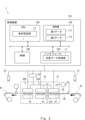
- FIG. 1 is a block diagram of a laminate molded product manufacturing system according to Embodiment 1.
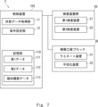
- FIG. 1 is a schematic configuration diagram of a laminate molded product manufacturing system according to a first embodiment
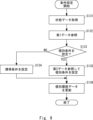
- FIG. 5 is a flowchart showing processing of the control device according to the first embodiment. It is a table showing first data. It is a table showing second data.
- FIG. 3 is a diagram showing estimated characteristic data.
- FIG. 2 is a block diagram of a laminate molded product manufacturing system according to a second embodiment.
- 7 is a flowchart showing the processing of the laminate molded product manufacturing system according to the second embodiment. It is a 1st flowchart which shows individual condition setting processing.
- FIG. 3 is a block diagram of a laminate molded product manufacturing system according to a third embodiment.
- FIG. 12 is a flowchart of a laminate molded product manufacturing system according to a third embodiment.
- 13 is a flowchart showing individual condition setting processing according to the third embodiment.
- FIG. 7 is a block diagram of a laminate molded product manufacturing system according to a fourth embodiment.
- FIG. 1 is a first diagram for explaining the steps of the laminate molded product manufacturing system.
- FIG. 2 is a second diagram for explaining the steps of the laminate molded product manufacturing system.
- FIG. 2 is a configuration diagram showing a specific example of a laminated molded product. It is a table showing third data.
- 12 is a flowchart showing the processing of the laminate molded product manufacturing system according to the fourth embodiment.
- FIG. 3 is a block diagram of a laminate molded product manufacturing system according to a fifth embodiment.
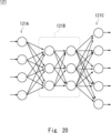
- FIG. 3 is a diagram showing a neural network of a learning section. It is a flowchart when a learning part performs learning.
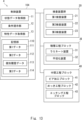
- FIG. 1 is a block diagram of a laminate molded product manufacturing system according to a first embodiment.
- the laminate molded product manufacturing system 1 manufactures a laminate molded product in which a plurality of layers of laminate films are laminated by repeating a lamination process in which a laminate film is laminated onto a processing object including at least a base material a plurality of times.
- the laminate molded product is, for example, a multilayer circuit board.
- the laminated molded product may be a wafer or other plate-shaped body in addition to a circuit board.
- the laminate molded product manufacturing system 1 mainly includes an inspection device group 20, a laminate process block 30, and a control device 101.
- the inspection device group 20 measures the state of the processing target including the base material introduced into the lamination process block 30, and generates state data.
- the inspection device group 20 is also communicably connected to the control device 101 and supplies the generated status data to the control device 101.
- the condition data is data indicating at least one of the following: the external shape of at least one of the processing object, the laminated film, and the laminated molded product, the unevenness of the surface, the temperature, the presence or absence of foreign matter, and the process history.
- the external shape includes the planar dimensions and thickness of the base material, laminate film, and laminate molded product to be treated.
- the thickness may include variation data at multiple predetermined locations. It is preferable that the state data is normalized by performing predetermined processing on the value measured for the processing target. However, the status data may be an index indicating the result of comparing a value measured on the processing target with a predetermined measurement standard, or a value itself obtained by measuring the processing target.
- the inspection device group 20 has sensors for generating these status data. Examples of the sensors include a visible light camera, an infrared sensor, a distance sensor, and a thermometer. The inspection device group 20 may also include sensors such as a thermometer and a hygrometer for measuring data related to the environment in which the processing target is processed. The inspection device group 20 may also include a calculation device for generating status data from signals acquired from these sensors.
- the inspection device group 20 mainly includes a first inspection device 21 and a second inspection device 22.
- the first inspection device 21 measures the state of the processing target input to the laminating device 31 and generates state data.
- the second inspection device 22 measures the state of the processing object, that is, the laminated molded product that has passed through the lamination process included in the lamination process block 30, and generates status data.
- the lamination process block 30 performs a lamination process of laminating and flattening a laminated film on the object to be treated.
- the lamination process block 30 is communicably connected to the control device 101, receives individual conditions presented from the control device 101, and performs the lamination process using the received individual conditions.
- the individual conditions are individual conditions of manufacturing parameters in the lamination process.
- the laminating process block 30 has a laminating device 31 and a flattening device 32 as main components.
- the laminating device 31 pressure-bonds the laminated films stacked on the object to be treated under reduced pressure.
- the processing target is, for example, a base material for manufacturing a build-up board, and may have an uneven pattern having a predetermined depth and interval.
- the flattening device 32 flattens the surface of the laminated molded product that has been subjected to the pressure bonding process on the object to be treated by the laminating device 31 .
- the control device 101 is communicably connected to each of the inspection device group 20 and the lamination process block 30, and controls the lamination molded product manufacturing system.
- the control device 101 has a state data acquisition section 11, a condition setting section 12, and a storage section 110 as main components.
- the status data acquisition unit 11 acquires status data from the inspection device group 20.
- the condition data acquisition unit 11 acquires, for example, status data related to the Nth (N ⁇ 1) lamination process before the Nth lamination process.
- the condition setting unit 12 uses the state data, first data, and second data to set individual conditions for the N-th lamination process. More specifically, for example, the condition setting unit 12 estimates characteristic data corresponding to the acquired status data by comparing the status data acquired by the status data acquisition unit 11 with the first data 111, and estimates the characteristic data corresponding to the acquired status data. By comparing the information and the second data 112, individual conditions for the lamination process are selected and presented.
- the condition setting unit 12 sets individual conditions in the lamination process block 30 in order to perform the lamination process according to the individual conditions.
- the condition setting unit 12 may display the lamination process block 30 on a predetermined display unit or the like as an index when the administrator who manages the storage unit 110 controls the lamination process block 30.
- the storage unit 110 is a storage device including nonvolatile memory such as flash memory, SSD (Solid State Drive), or HDD (Hard Disk Drive).
- the storage unit 110 stores first data 111 and second data 112.
- the first data 111 indicates the relationship between the above-mentioned status data and characteristic data.
- the characteristic data is data related to at least one of voids, material outflow, wrinkles, misalignment, foreign matter inclusion, deformation, and pressure unevenness in the laminated molded product after the lamination process. That is, the characteristic data is data including items related to the quality of the laminate molded product. Note that the above-mentioned status data and characteristic data may include items that overlap with each other.
- the second data 112 shows the relationship between the characteristic data and the process parameters set for the lamination process.
- the process parameters are parameters that are set when the laminating device 31 and flattening device 32 included in the laminating process block 30 perform a predetermined process on a processing object.
- Process parameters include, for example, the conveyance speed when the lamination process block 30 conveys the processing object, the temperature set in the laminating device 31 and the flattening device 32, and the pressure when the laminating device 31 and the flattening device 32 press the processing object. etc.
- FIG. 2 is a schematic configuration diagram of the laminate molded product manufacturing system according to the first embodiment.
- an upper conveyance sheet 35 and a lower conveyance sheet 36 are unwound from the right side of the figure and wound up on the left side of the figure.
- the upper conveying sheet 35 and the lower conveying sheet 36 sandwich the processing target A1 at the right end of the figure (that is, the upstream side of the processing process), and move the stacking process block 30 while holding the processing target A1. pass.
- the upper conveyance sheet 35 and the lower conveyance sheet 36 release the processing object A1 that has passed through the stacking process block 30 on the left side of the drawing (that is, on the downstream side of the processing process).
- the processing target A1 is, for example, a base material for manufacturing a build-up board, and may have a fine uneven pattern on its surface having a predetermined depth and interval.
- the upper conveyance sheet 35 and the lower conveyance sheet 36 are formed, for example, by forming polyethylene terephthalate into a belt shape.
- the upper conveyance sheet 35 and the lower conveyance sheet 36 are wound up at the left and right ends of the lamination process block 30 shown in FIG. It can be transported while being sandwiched.
- the first inspection device 21 generates state data by photographing the processing target A1 placed on the lower conveyance sheet 36 on the upstream side of the laminate molded product manufacturing system 1.
- the first inspection device 21 measures the shape of the processing object A1 or the position of the processing object A1 with respect to the lower conveyance sheet 36 by photographing the processing object A1.
- the processing object A1 may include a distance measuring sensor capable of measuring the uneven state of the surface of the processing object A1.
- the first inspection device 21 may include a photographing device that photographs the processing target A1 from below the lower conveyance sheet 36 through the lower conveyance sheet 36.
- the second inspection device 22 generates state data by photographing the processing target A1 after passing through the lamination process block 30 on the downstream side of the laminated molded product manufacturing system 1.
- the second inspection device 22 may have the same configuration as the first inspection device 21 or may have a different configuration from the first inspection device 21.
- the stacking process block 30 receives the processing object A1 transported by the upper transport sheet 35 and the lower transport sheet 36, and performs a predetermined process on the received processing object A1.
- the laminating process block 30 has a laminating device 31 and a flattening device 32 in this order from the upstream side.
- the laminating device 31 When the laminating device 31 receives the processing target A1, it applies pressure in the vertical direction to laminate the temporarily bonded laminated films.
- the laminating device 31 includes, for example, an upper laminating section 311 and a lower laminating section 312.
- the laminating device 31 performs lamination processing by sandwiching the processing target A1 between an upper laminating processing section 311 and a lower laminating processing section 312 and applying pressure.
- the laminating device 31 may have a diaphragm mechanism that bulges the flexible sheet in at least one of the upper laminating section 311 and the lower laminating section 312.
- the laminating apparatus 31 may include a heat-resistant resin in at least one of the upper laminating processing section 311 and the lower laminating processing section 312 to follow the unevenness of the surface of the processing object A1.
- the heat-resistant resin include polyimide, fluororesin, and silicone resin.
- the laminating device 31 may form a chamber capable of reducing the pressure.
- the flattening device 32 shown in FIG. 2 includes a first flattening device 32A and a second flattening device 32B.
- the first flattening device 32A receives the processing object A1 laminated by the laminating device 31, and performs a flattening process on the received processing object A1.
- the processing target A1 subjected to the flattening process by the first flattening device 32A is conveyed to the second flattening device 32B by the upper conveyance sheet 35 and the lower conveyance sheet 36.
- the second flattening device 32B receives the processing target A1 that has been flattened by the first flattening device 32A, and flattens the processing target A1 by further flattening the received processing target A1.
- the thickness of the processing target A1 is further reduced to a desired thickness.
- the process of the planarization process can be dispersed or distributed, and the processing target A1 can be suitably planarized.
- the processing target A1 subjected to the flattening process by the second flattening device 32B is conveyed to the downstream side of the flattening device 32 by a conveyance sheet.
- the temperature control device 33 is connected to the laminating device 31 and has a function of controlling the temperature of a predetermined portion of the laminating device 31. Further, the temperature control device 33 is connected to the first flattening device 32A and the second flattening device 32B, and controls the temperature of the heating bodies each of these has. Thereby, the laminating device 31, the first flattening device 32A, and the second flattening device 32B apply predetermined heat and pressure to the processing target A1. Note that the temperature control device 33 can control the laminating device 31, the first flattening device 32A, and the second flattening device 32B to different temperatures.
- the control device 101 is a circuit including a calculation device.
- the control device 101 is communicatively connected to a first inspection device 21, a second inspection device 22, a laminating device 31, a flattening device 32, and a temperature control device 33.
- the control device 101 has a CPU 120 (Central Processing Unit), NVRAM 130 (Non-Volatile Random-Access Memory), DRAM 140 (Dynamic Random-Access Memory), and an interface 150 as main components. Further, the above-mentioned configuration of the control device 101 is communicably connected via a predetermined communication bus.
- the CPU 120 is a calculation device and controls each component of the control device 101. Further, the CPU 120 includes a condition setting section 12.
- NVRAM 130 is a nonvolatile memory and stores first data 111 and second data 112.
- the DRAM 140 temporarily stores data when the CPU 120 performs calculations, and when the control device 101 starts a predetermined application program, it develops the application program into an operational state.
- the interface 150 is an interface for communicating with the first inspection device 21 , the second inspection device 22 , and the lamination process block 30 to which the control device 101 is connected, and includes the status data acquisition unit 11 .
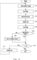
- FIG. 3 is a flowchart showing the processing of the control device 101 according to the first embodiment.
- the storage unit 110 of the control device 101 stores first data indicating the relationship between state data and characteristic data (step S1).
- the storage unit 110 of the control device 101 stores second data indicating the relationship between the characteristic data and the process parameters set for the lamination process (step S2).
- control device 101 acquires state data regarding the Nth (N ⁇ 1) lamination process (step S3).
- control device 101 sets individual conditions for the N-th lamination process from the above-mentioned state data, first data, and second data (step S4). After setting the individual conditions to be applied to the processing target A1, the control device 101 ends the series of processing.
- step S1 and step S2 may be reversed. Step S1 and step S2 may be performed in parallel. Moreover, after step S1 and step S2 are executed once, the control device 101 can be set to repeat step S3 and step S4.
- FIG. 4 is a table showing the first data 111.
- the first data 111 shown in FIG. 4 shows items such as “material,” “thickness,” “surface roughness,” and “environmental temperature” as state data in horizontal columns.
- the first data 111 shows items such as "void”, “material outflow”, “wrinkle”, and "positional shift” as characteristic data in columns arranged vertically.
- predetermined index values are entered in the intersecting columns of the matrix created by the above items. This index value is set so that estimated characteristic data can be calculated when the state data acquired by the state data acquisition unit 11 is applied.
- the first data 111 is related to, for example, what is the possibility of material leakage when the thickness of a specific material exceeds a predetermined value and the environmental temperature is higher than a predetermined temperature. . Therefore, the control device 101 can estimate, for example, the possibility of quality defects by comparing the state data acquired by the state data acquisition unit 11 and the first data 111. Alternatively, the control device 101 can estimate not only the possibility of quality defects but also the possibility of meeting predetermined specifications, for example.
- Estimated characteristic data generated by comparing the state data acquired by the state data acquisition unit 11 with the first data 111 can be shown as an index normalized for each item.
- the form of the estimated characteristic data is not limited to this.
- the estimated characteristic data may extract items that have a relatively high possibility of not meeting a predetermined quality standard.
- the estimated characteristic data may be one that extracts items that have a relatively high possibility of having a predetermined quality.
- FIG. 5 is a table showing the second data.
- items such as "setting item 1", “setting item 2", “setting item 3", etc. are shown as individual conditions of manufacturing parameters in horizontal columns.
- the setting items include, for example, the conveyance speed of the conveyance sheet, the temperature set for each of the lamination process blocks 30, the pressure set for each of the lamination process blocks 30, etc.
- the second data 112 includes characteristic data such as "void”, “material outflow”, “wrinkle”, and "positional shift” in columns arranged vertically. Further, in the second data 112, predetermined index values are entered in the intersecting columns of the matrix created by the above items. This index value is set so that individual conditions can be presented when the estimated characteristic data generated by the condition setting unit 12 is applied.
- condition setting unit 12 calculates estimated characteristic data from the status data acquired by the status data acquisition unit 11 and the first data 111 read from the storage unit 110. Thereafter, the condition setting unit 12 compares the generated estimated characteristic data with the second data 112 shown in FIG. Thereby, the condition setting unit 12 selects the individual condition corresponding to the estimated characteristic data. Therefore, the condition setting section 12 can set the selected individual condition.
- first data 111 shown in FIG. 4 and the second data 112 shown in FIG. 5 are examples, and the first data 111 and second data 112 are not limited to the above-mentioned format.
- the first data 111 may constitute a regression equation for the condition setting unit 12 to perform multiple regression analysis to calculate the estimated characteristic data.
- second data 112 may constitute a regression equation for multiple regression analysis for the condition setting unit 12 to set individual conditions.
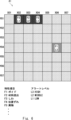
- FIG. 6 is a diagram showing estimated characteristic data.
- FIG. 6 shows the main surface of the processing target A1 divided into a matrix and defective items that may occur in each divided area.
- the rectangular processing target A1 is divided from X01 to X07 in the horizontal direction, and from Y01 to Y07 in the vertical direction, starting from the upper left. That is, the processing target A1 is divided into a total of 49 areas, from area (X01, Y01) to area (X07, Y07). Further, in the processing target A1, a defective item and an alert level are assigned to each area.
- characteristic item F2 material outflow
- alert levels L1 LOW
- L2 MIDDLE
- characteristic item F1 void
- alert level L3 HGH
- the estimated characteristic data may include data regarding the area and characteristics in the processing target A1. Based on such data, the condition setting unit 12 sets individual conditions so that among the characteristic items shown in the above-mentioned estimated characteristic data, items with high alert levels do not fall below a predetermined quality level.
- the laminate molded product manufacturing system 1 according to Embodiment 1 is not limited to the above-described configuration.
- the laminate molded product manufacturing system 1 may have one flattening device 32, or may have two or more flattening devices 32.
- the lamination process block 30 may not include the planarization device 32.
- the laminate molded product manufacturing system 1 selects and presents individual conditions of manufacturing parameters from the state data acquired by the state data acquisition unit 11. Thereby, the laminated molded product manufacturing system 1 can individually set suitable conditions when inputting the processing object A1 whose state data has been acquired into the lamination process. That is, according to this embodiment, it is possible to provide a control device and the like that contribute to improving yield and processing accuracy.
- FIG. 7 is a block diagram of a laminate molded product manufacturing system 2 according to the second embodiment.
- the status data acquisition unit 11 according to the present embodiment acquires status data that includes identification data that is uniquely linked to the processing target A1.
- the storage unit 110 stores individual history data 113.
- the storage unit 110 stores individual history data of the lamination process associated with the processing target related to the identification data in association with the laminated molded product.
- the condition setting unit 12 includes individual history data in the state data and sets individual conditions.
- the laminate molded product manufacturing system 2 identifies the processing object A1 by reading identification data such as predetermined symbols, numbers, characters, labels, barcodes, two-dimensional codes, three-dimensional codes, etc. attached to the processing object, for example. Good too.
- the laminate molded product manufacturing system 2 may identify the processing object A1 by reading identification data via an IC tag or the like attached to the processing object.
- the laminate molded product manufacturing system 2 may include an identification device (also referred to as a serialization device) for adding identification data to a processing target.
- the identification device is a device that adds identification data by stamping or printing the identification data.
- the status data acquired by the status data acquisition unit 11 according to the present embodiment includes identification data for the processing target.
- the condition setting unit 12 then presents individual conditions according to the identification data.
- the status data of this processing object includes identification data N0001.
- the status data acquisition unit 11 stores this status data in the storage unit 110 as individual history data 113 including identification data N0001.
- the processing target is, for example, a base material for manufacturing a build-up board, and may have an uneven pattern having a predetermined depth and interval.
- the storage unit 110 stores individual history data 113.
- the individual history data 113 is obtained by linking state data acquired by the control device 102 at a plurality of different times using identification data.
- the individual history data of identification data N0001 may include a history of a lamination process in which a plurality of layers of laminated films are laminated from a state to be processed, and state data of processes before and after each lamination process. That is, the individual history data of the identification data N0001 may also include data on the type of process that the processing target undergoes, the number of processes, the conditions of the process, the time required for the process, and the inspection results between each process, in addition to the lamination process.
- the individual history data of identification data N0001 may include, for example, the heating temperature and heating time in the heat treatment process performed after the lamination process, and the waiting time between each process.
- the condition setting unit 12 reads the individual history data 113 and sets individual conditions by taking the read individual history data 113 into account.
- condition setting unit 12 determines whether the estimated characteristic data exceeds a predetermined standard threshold, and if the estimated characteristic data does not exceed the standard threshold, sets the predetermined standard instead of the individual condition. Provide parameters.
- the laminated molded product manufacturing system 2 performs the lamination process using uniform manufacturing parameters for laminated molded products that meet a certain quality level, and individually performs the lamination process for processing target A1 that may not meet the above quality level. By setting conditions, the quality level can be improved.
- FIG. 8 is a flowchart showing the processing of the laminate molded product manufacturing system according to the second embodiment.
- the flowchart shown in FIG. 8 is started, for example, when the laminate molded product manufacturing system 2 receives a new base material as a processing target.
- the laminate molded product manufacturing system 2 recognizes the identification data of the processing target A1 (step S11). For example, the laminate molded product manufacturing system 2 recognizes the identification data linked to the processing object A1 by reading the identification data attached to the processing object in advance.
- the first inspection device 21 of the laminate molded product manufacturing system 2 performs a first inspection (step S12).
- the first inspection device 21 generates status data.
- the first inspection device 21 generates status data including identification data.
- the first inspection device 21 supplies the generated state data to the control device 102.
- step S13 the laminate molded product manufacturing system 2 sets conditions for processing the processing target A1 (step S13). Note that details of step S13 will be described later.
- the laminated molded product manufacturing system 2 inputs the processing target A1 into the lamination process block 30 and executes the lamination process (step S14). Note that at this time, the laminate molded product manufacturing system 2 uses the conditions set in step S13. When the lamination process is completed, the lamination molded product manufacturing system 2 transports the processing target A1 out of the lamination process block 30 and supplies it to the second inspection device 22.
- the second inspection device 22 performs a second inspection (step S15).
- the laminated molded product manufacturing system 2 determines whether the number n of lamination steps performed on the processing object A1 is less than a preset specified value Ns (step S16).
- the laminate molded product manufacturing system 2 may recognize the number n by detecting the number of layers in the second inspection, or may recognize the number n by reading the individual history data 113 from the storage unit 110. .
- step S16 If it is determined that the number of times n of the lamination process is less than the preset specified value Ns (step S16: YES), the laminated molded product manufacturing system 2 moves to the circuit forming process (step S17) and returns to step S11.
- the circuit forming process includes, for example, heat treatment, via processing, plating, etching, etc., but is not limited to these.
- step S16: NO the laminated molded product manufacturing system 2 ends the series of processes.
- FIG. 9 is a first flowchart showing the individual condition setting process.
- the flowchart shown in FIG. 8 is details of step S13 in the flowchart of FIG.
- the status data acquisition unit 11 acquires status data (step S131).
- condition setting unit 12 refers to the first data (step S132), collates the state data and the first data, and calculates estimated characteristic data.
- the condition setting unit 12 determines whether to set individual conditions from the calculated estimated characteristic data (step S133). Specifically, for example, the condition setting unit 12 makes the above determination by comparing a value indicating a predetermined characteristic in the estimated characteristic data with a predetermined threshold corresponding to the standard condition. If it is determined that individual conditions are to be set (step S133: YES), the condition setting unit 12 proceeds to step S135. If it is not determined that individual conditions are to be set (step S133: NO), the condition setting unit 12 proceeds to step S134.
- step S134 the condition setting unit 12 sets preset standard conditions instead of the individual conditions (step S134), and proceeds to step S136.
- step S135 the condition setting unit 12 sets individual conditions with reference to the second data 112 (step S135), and proceeds to step S136.
- step S136 the control device 102 updates the individual history data 113 stored in the storage unit 110 (step S136). Specifically, the control device 102 adds, for example, the state data acquired by the state data acquisition unit 11 and the conditions set in step S134 or step S135 to the individual history data 113.
- the laminated molded product manufacturing system 2 processes the processing object A1 to which a plurality of lamination processes are performed, the state data acquired before performing each lamination process, and the individual history data linked to the processing object A1.
- the conditions for the lamination process can be set using the following.
- the laminate molded product manufacturing system 2 suitably sets the individual conditions for the processing target A1. Therefore, according to this embodiment, it is possible to provide a control device and the like that contribute to improving yield and processing accuracy.
- Embodiment 3 differs from the above-described embodiments in that characteristic data is generated in an inspection after the lamination process.
- FIG. 10 is a block diagram of the laminate molded product manufacturing system 3 according to the third embodiment.
- the laminate molded product manufacturing system 3 includes a control device 103.
- the control device 103 differs from the control device according to the second embodiment in that it includes a characteristic data acquisition section 13.
- the characteristic data acquisition unit 13 acquires, for example, characteristic data of the laminated molded product after the Nth lamination process.
- the condition setting unit 12 sets the individual conditions by adding at least a part of the N-th characteristic data to the state data in the N+1-th stacking process.
- FIG. 11 is a flowchart of the laminate molded product manufacturing system according to the third embodiment.
- the flowchart shown in FIG. 11 differs from the flowchart shown in FIG. 8 in the processing between step S15 and step S16.
- step S151 the laminate molded product manufacturing system 3 determines whether the second inspection passes. Standards for normal manufacturing processes may be applied to determine whether the second inspection passes or not. If the second inspection is determined to pass (step S151: YES), the laminate molded product manufacturing system 3 proceeds to step S16. The processing in this case is similar to that shown in FIG. On the other hand, in the second inspection, if any characteristic falls below the predetermined quality level, the laminate molded product manufacturing system 3 does not determine that the second inspection is passed. In this case (step S151: NO), the laminate molded product manufacturing system 3 proceeds to a process of considering adjustment of conditions (step S20), and then proceeds to step S16.
- FIG. 12 is a flowchart showing the individual condition setting process according to the third embodiment.
- the control device 103 acquires second inspection data from the second inspection device 22 (step S201).
- the second inspection data includes identification data and characteristic data of the processing target A1 after the lamination process.
- the condition setting unit 12 generates state data from at least part of the acquired characteristic data, and calculates estimated characteristic data with reference to the first data 111 (step S202).
- the estimated characteristic data calculated here is based on the individual conditions when the N+1th lamination process is further performed on the processing object A1 that was not determined to pass in the second inspection conducted after the Nth lamination process. It is used to determine whether or not the quality level can be improved by applying this method.
- the control device 103 determines whether individual conditions can be set from the calculated estimated characteristic data (step S203). If it is determined that the individual conditions can be set (step S203: YES), the condition setting unit 12 refers to the second data to set the individual conditions (step S204), and proceeds to step S206. On the other hand, if the predetermined quality level cannot be maintained even if the individual conditions are applied, the control device 103 does not determine that the individual conditions can be set. In this case (step S203: NO), the condition setting unit 12 proceeds to step S205.
- step S205 the laminate molded product manufacturing system 3 removes the processing target A1 from the line (step S205), and proceeds to step S206.
- step S206 the control device 103 updates the individual history data 113. For example, when the individual conditions are set in step S204, the control device 103 may add the set individual conditions to the individual history data 113. For example, when the processing target A1 is to be removed from the line in step S205, the control device 103 adds information indicating that the processing target A1 is removed to the identification data related to the processing target A1 to be removed.
- Embodiment 3 has been described above. With the above-described configuration, the laminate molded product manufacturing system 3 sets individual conditions when the quality level can be modified based on the characteristic data of the laminate molded product after the Nth lamination process. Therefore, according to this embodiment, it is possible to provide a control device and the like that contribute to improving yield and processing accuracy.
- FIG. 13 is a block diagram of a laminate molded product manufacturing system 4 according to the fourth embodiment.
- the laminate molded product manufacturing system 4 differs from the embodiment described above in that it further includes an intermediate process block 40.
- the inspection device group 20 further includes a third inspection device 23.
- the third inspection device 23 measures items related to the shape, function, etc. of the processing object A1 to which the intermediate process block 40 has been applied, and generates characteristic data in the intermediate process (intermediate characteristic data).
- the intermediate process block 40 receives the laminate molded product that has passed through the lamination process block 30, and performs a predetermined intermediate process using this laminate molded product as the processing target A1.
- the intermediate process is, for example, a circuit forming process such as heat treatment, via processing, plating, or etching, but the intermediate process is not limited to these.
- the intermediate process block 40 according to this embodiment includes a via processing process block 41, a plating process block 42, and an etching process block 43.
- the via machining process block 41 performs a cutting process to generate vias on the surface of the laminated molded product after passing through the lamination process block 30.
- the via processing block 41 includes a dedicated device for performing via processing.
- the plating process block 42 performs plating on the via-processed processing object A1 using a predetermined method.
- the etching process block 43 performs an etching process to form a predetermined circuit pattern on the plated processing object A1. Both the plating process block 42 and the etching process block 43 each include dedicated equipment.
- the intermediate process block 40 is communicably connected to the control device 104.
- the control device 104 manages parameters set when the intermediate process block 40 performs various processes.
- the control device 104 may directly control the intermediate process block 40, or may present predetermined parameters or processing conditions set to the intermediate process block 40.
- control device 104 presents processing conditions set in the intermediate process block 40
- the administrator who manages the control device 104 can execute the intermediate process according to the presented conditions.
- the control device 104 may have a display device for presenting such conditions, or an external computer, etc.
- the computer may also include a communication device for displaying the conditions.
- the control device 104 stores third data 114 in the storage unit 110.
- the third data 114 includes, for example, intermediate characteristic data of a laminate molded product in intermediate processing performed on the processing object between the N-th lamination process and the N+1-th lamination process, and the processing object before the intermediate process. This is data showing the relationship with characteristic data regarding.
- the third data 114 includes data indicating characteristics regarding at least one of plating treatment, cutting treatment, and etching treatment performed on the processing target in the intermediate treatment.
- the condition setting unit 12 sets individual conditions regarding intermediate processing. At this time, the condition setting unit 12 uses the state data, first data, second data, and third data.
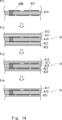
- FIG. 14 is a first diagram for explaining the steps of the laminate molded product manufacturing system.
- FIG. 14 shows a first process P11, a second process P12, a third process P13, and a fourth process P14 in order from top to bottom.
- the processing target A1 is subjected to via processing and circuit pattern formation.
- the processing target A1 is a plate material formed by mixing glass fiber and epoxy resin, for example.
- the via A30 and the circuit pattern A31 are formed by etching copper plating.
- the second step P12 shows a state in which thermosetting laminated films A11 and A21 are temporarily adhered to the surface of the object A1 to be treated in the first step.
- Protective films A12 and A22 are attached to the outside of the laminated films A11 and A21 to protect the laminated films during lamination processing.
- the processing target A1 shown in the second process P12 is in a state before being put into the lamination process block 30.
- the processing target A1 shown in the third step P13 is in a state after being input into the lamination step block 30.
- the third step P13 shows a state in which the laminated films A11 and A21, which were temporarily bonded in the second step, are laminated onto the processing target A10 and then subjected to a flattening treatment.
- the processing target A1 shown in the fourth step P14 is shown in a state in which the protective film is removed after being taken out from the lamination step block 30. After the fourth step P14, the processing target A1 proceeds to an intermediate step.
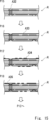
- FIG. 15 is a second diagram for explaining the process of the laminate molded product manufacturing system.
- FIG. 15 shows a fifth step P15, a sixth step P16, a seventh step P17, and an eighth step P18 as steps after FIG. 14 from top to bottom.
- the fifth step P15 shows a state in which via processing has been performed on the processing target A1 after the fourth step P14.
- a via A32 is processed in the processing target A1 showing the fifth step P15.
- the via A32 is cut using a laser beam such as a gas laser or a YAG laser.
- the sixth step P16 shows a state in which electroless plating has been applied to the surface of the processing object A1.
- a processing target A1 covered with a copper foil A33 is shown in the sixth step P16.
- the seventh step P17 shows a state in which a dry resist film A34 is attached to the surface of the copper foil A33.
- the dry resist film A34 has a predetermined circuit pattern formed of, for example, photoresist.
- the eighth step P18 is copper plating A35 formed by the circuit pattern formed by the dry resist film A34.
- the copper plating A35 is a state in which the dry resist film A34 and the electroless plating laid directly under the dry resist film A34 are removed by corrosion and dissolution after the processing target A1 of the seventh step P17 is electrolytically plated. Note that when the eighth step P18 is completed, the processing target A1 is a four-layer substrate, but if a multilayer substrate is to be manufactured from this, the process returns to the second step and the lamination step and intermediate step are repeated.
- FIG. 16 is a configuration diagram showing a specific example of a laminated molded product.
- the laminated molded product A100 shown in FIG. 16 three layers of laminated films are laminated on each side of the processing object A10, and each laminated film is subjected to via processing, plating, etc.
- the laminate molded product A100 is called a build-up board or a multilayer board.
- the laminate molded product manufacturing system 4 manufactures a multilayer substrate as shown here by performing the processes from the first step P11 to the eighth step P18.
- FIG. 17 is a table showing the third data 114.
- items such as "setting item 1," “setting item 2,” and “setting item 3" are shown in horizontal columns as individual conditions for intermediate process manufacturing parameters.
- the setting items are parameters such as temperature, humidity, and time that are set in the above-mentioned intermediate process.
- the third data 114 includes characteristic data such as "void”, “material outflow”, “wrinkle”, and "positional shift” in columns arranged vertically. Further, in the third data 114, predetermined index values are entered in the intersecting columns of the matrix created by the above items. This index value is set so that individual conditions for intermediate steps can be presented when the estimated characteristic data generated by the condition setting unit 12 is applied.
- the third data 114 shown in FIG. 17 is an example, and the third data 114 is not limited to the above format.
- the third data 114 may constitute a regression equation for the condition setting unit 12 to perform multiple regression analysis to calculate the estimated characteristic data.
- the second data 112 may constitute a regression equation for multiple regression analysis for the condition setting unit 12 to set individual conditions.
- FIG. 18 is a flowchart showing the processing of the control device 104 according to the fourth embodiment.
- the flowchart shown in FIG. 18 is started, for example, after the inspection process by the second inspection device 22 is completed.
- the characteristic data acquisition unit 13 of the control device 104 acquires the second inspection data (step S411).
- condition setting unit 12 refers to the first data 111 (step S412). Then, the condition setting unit 12 calculates estimated characteristic data from the state data generated from the acquired second test data and the first data 111.
- condition setting unit 12 refers to the third data 114 (step S413). Then, the condition setting unit 12 sets individual conditions for the intermediate process from the calculated estimated characteristic data and the third data 114 (step S414).
- control device 104 updates the individual history data 113 (step S415) and ends the series of processing.
- control device and the like that contribute to improving yield and processing accuracy in a manufacturing system including various processes for manufacturing, for example, a multilayer substrate.
- FIG. 19 is a block diagram of a laminate molded product manufacturing system 5 according to the fifth embodiment.
- the laminate molded product manufacturing system 5 according to this embodiment includes a control device 105.
- the control device 105 differs from the above embodiment in that it includes a learning processing section 14. Note that the storage unit 110 included in the control device 105 does not have the first data and the second data. In the control device 105, the learning processing unit 14 has a function corresponding to first data and second data. That is, the learning processing unit 14 is a learning model set to perform calculations corresponding to the first data and the second data by machine learning.
- the learning processing unit 14 calculates estimated characteristic data from the state data using, for example, a first learning processing unit that has learned state data and characteristic data as teacher data. Further, the learning processing unit 14 sets individual conditions from the estimated characteristic data using a second learning processing unit that has learned parameters set in the lamination process and characteristic data measured after the lamination process as teacher data.
- the learning processing unit 14 uses AI (Artificial Intelligence) technology, which is artificial intelligence, to learn the relationship between the state data and characteristic data of the processing target A1, and estimates the characteristic data of the processing target A1.
- AI Artificial Intelligence
- the learning processing unit 14 uses AI technology to learn the relationship between the characteristic data and the setting conditions of the lamination process, and generates individual conditions for processing the processing target A1 before performing the lamination process.
- FIG. 20 is a diagram showing an example of the structure of the learning processing section 14.
- FIG. 20 shows the learning processing section 14.
- the learning processing unit 14 shown in FIG. 20 generates, for example, first data.
- the learning processing unit 14 includes an input layer 121A, an intermediate layer 121B, and an output layer 121C.
- the intermediate layer 121B is also called a hidden layer.
- the intermediate layer 121B is provided between the input layer 121A and the output layer 121C.
- the input layer 121A has a plurality of nodes, and receives state data included in the data set as input.
- the intermediate layer 121B has a plurality of nodes. Note that the number of nodes and the number of hidden layers included in the intermediate layer shown in the figure are merely examples, and the number of nodes and the number of layers are not limited to these. Similarly, the number of nodes in the input layer and output layer shown in the figure is an example and is not limited thereto.
- the learning processing unit 14 When the learning processing unit 14 receives the state data, it outputs a predetermined numerical value to the output layer 121C. The output of the output layer 121C is checked against teacher data, and the checked results are fed back. The learning processing unit 14 updates the threshold value, weighting, etc. in the learning model by repeating this process.
- the learning processing unit 14 may be configured to learn the relationship between the state data of the processing target A1 and the setting conditions of the lamination process, and generate individual conditions for setting.
- the condition setting unit 12 may use a learning model generated by the learning processing unit 14 instead of the first data 111 and the second data 112.
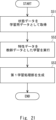
- FIG. 21 is a flowchart when the learning processing unit 14 performs learning.
- the flowchart shown in FIG. 21 is a flowchart when the learning processing section 14 generates the first learning processing section.
- the learning processing unit 14 acquires state data as learning data (step S51).
- the learning processing unit 14 executes learning using the characteristic data corresponding to the input state data as teacher data (step S52).
- the learning processing unit 14 generates a first learning processing unit that is a trained model updated by the learning performed (step S53).
- the learned model refers to a learning model that has been updated through the above-described process and is now ready for use.
- the first learning processing unit performs reinforcement learning from the estimated characteristic data calculated from the state data acquired by the status data acquisition unit 11 in the operation stage and the characteristic data acquired by the characteristic data acquisition unit 13, and performs the first learning processing. You may update the section.
- the second learning processing section performs reinforcement learning from the conditions set in the stacking process block 30 in the operation stage and the characteristic data acquired by the characteristic data acquisition section 13, and even if the second learning processing section is updated. good.
- the laminate molded product manufacturing system 5 can improve the accuracy of the learning processing section 14 while acquiring state data and characteristic data. Thereby, the laminate molded product manufacturing system flexibly presents or sets suitable conditions. Therefore, according to this embodiment, it is possible to provide a control device and the like that contribute to improving yield and processing accuracy.
- the present invention can be used, for example, in a laminated molded product manufacturing system for manufacturing multilayer substrates.
- Laminated molded product manufacturing system 1 Laminated molded product manufacturing system 2 Laminated molded product manufacturing system 3 Laminated molded product manufacturing system 4 Laminated molded product manufacturing system 5 Laminated molded product manufacturing system 11 Condition data acquisition section 12 Condition setting section 13 Characteristic data acquisition section 14 Learning processing section 20 Inspection Device group 21 First inspection device 22 Second inspection device 23 Third inspection device 30 Lamination process block 31 Lamination device 32 Flattening device 33 Temperature control device 35 Upper conveyance sheet 36 Lower conveyance sheet 40 Intermediate process block 41 Via processing process Block 42 Plating process block 43 Etching process block 101 Control device 102 Control device 103 Control device 104 Control device 105 Control device 110 Storage section 111 First data 112 Second data 113 Individual history data 114 Third data 120 CPU 130 NVRAM 140 DRAM 150 Interface A1 Processing target
Landscapes
- Engineering & Computer Science (AREA)
- Manufacturing & Machinery (AREA)
- Microelectronics & Electronic Packaging (AREA)
- Lining Or Joining Of Plastics Or The Like (AREA)
- Production Of Multi-Layered Print Wiring Board (AREA)
- Casting Or Compression Moulding Of Plastics Or The Like (AREA)
- Laminated Bodies (AREA)
Abstract
制御装置(101)は、基材を少なくとも含む処理対象に積層フィルムをラミネートする積層工程を複数回繰り返すことで積層成形品を製造する積層成形品製造システム(1)を制御する。上記制御装置(101)において、記憶部(110)は、第1データ(111)および第2データ(112)を記憶する。第1データ(111)は、処理対象または積層フィルムの状態データと積層工程の後の積層成形品における特性データとの関連を示す。第2データ(112)は、特性データと積層工程に設定される工程パラメータとの関連を示す。状態データ取得部(11)は、N回目の積層工程にかかる状態データを取得する。条件設定部(12)は、状態データと、第1データ(111)と第2データ(112)とに基づいて、N回目の積層工程における個別条件を設定する。
Description
本発明は制御装置、積層成形品製造システムおよび積層成形品の製造方法に関する。
積層成形品の成形不良の判断の少なくとも一部を作業者によらずに行うことができる技術が開発されている。
例えば特許文献1に開示されている真空積層成形品製造システムは、真空積層装置の上盤と下盤の間に形成される真空チャンバ内で押圧体により積層成形品を加圧して積層成形を行うものであって、検出装置および機械学習装置を有している。検出装置は、真空積層装置の後工程に設けられ積層成形された積層成形品のデータを検出する。機械学習装置は、検出されたデータを基礎にして積層成形品の画像を良品と不良品とに区別して学習し、少なくとも連続成形時に積層成形品を検出装置で検出して良品または不良品のいずれかであると判断する。
上述の技術は、検査データをマスデータとして捉え、検査基準を作成する。そのためこの技術は、マスプロダクションにおいて成形不良の判断の少なくとも一部を作業者によらずに行うことができる。しかしながら、真空積層成形品製造システムの生産効率をさらに向上させるための技術が期待されている。
本開示は、このような課題を解決するためになされたものであって、歩留まりや処理精度の向上に寄与する制御装置等を提供するものである。
本開示にかかる制御装置は、基材を少なくとも含む処理対象に積層フィルムをラミネートする積層工程を複数回繰り返すことで複数層の積層フィルムが積層された積層成形品を製造する積層成形品製造システムを制御する。上記制御装置は、記憶部、状態データ取得部および条件設定部を有する。記憶部は、第1データおよび第2データを記憶する。第1データは、処理対象または積層フィルムの外形、表面の凹凸状態、温度、異物の有無の状態、工程履歴の少なくとも1つを示す状態データと積層工程の後の積層成形品における、ボイド、材料流出、しわ、位置ずれ、異物混入、変形、加圧ムラの少なくとも1つに関連する特性データとの関連を示す。第2データは、特性データと積層工程に設定される工程パラメータとの関連を示す。状態データ取得部は、N回目(N≧1)の積層工程にかかる状態データを取得する。条件設定部は、状態データと、第1データと第2データとに基づいて、N回目の積層工程における個別条件を設定する。
本開示にかかる制御装置は、基材を少なくとも含む処理対象に積層フィルムをラミネートする積層工程を複数回繰り返すことで複数層の積層フィルムが積層された積層成形品を製造する積層成形品製造システムを制御する。上記制御装置は、第1学習処理部、第2学習処理部、状態データ取得部および条件設定部を有する。第1学習処理部は、処理対象または積層フィルムの外形、表面の凹凸状態、温度、異物の有無の状態、工程履歴の少なくとも1つを示す状態データと積層工程の後の積層成形品における、ボイド、材料流出、しわ、位置ずれ、異物混入、変形、加圧ムラの少なくとも1つに関連する特性データとの関連を学習することにより、状態データに基づいて特性データを推定する。第2学習処理部は、特性データと積層工程に設定される工程パラメータとの関連を学習することにより、特性データに基づいて工程パラメータの個別条件を算出する。状態データ取得部は、N回目(N≧1)の積層工程にかかる状態データを取得する。条件設定部は、状態データと、第1学習処理部が推定する推定特性データと第2学習処理部が算出する個別条件とに基づいて、N回目の積層工程における個別条件を設定する。
本開示にかかる積層成形品の製造方法は、基材を少なくとも含む処理対象に積層フィルムをラミネートする積層工程を複数回繰り返すことで複数層の積層フィルムが積層された積層成形品を製造する積層成形品製造システムの制御装置が以下の処理を実行する。制御装置は、処理対象または積層フィルムの外形、表面の凹凸状態、温度、異物の有無の状態、工程履歴の少なくとも1つを示す状態データと積層工程の後の積層成形品における、ボイド、材料流出、しわ、位置ずれ、異物混入、変形、加圧ムラの少なくとも1つに関連する特性データとの関連を示す第1データを記憶する。制御装置は、特性データと積層工程に設定される工程パラメータとの関連を示す第2データを記憶する。制御装置は、N回目(N≧1)の積層工程にかかる状態データを取得する。制御装置は、状態データと、第1データと第2データとに基づいて、N回目の積層工程における個別条件を設定する。
本開示にかかる積層成形品の製造方法は、基材を少なくとも含む処理対象に積層フィルムをラミネートする積層工程を複数回繰り返すことで複数層の積層フィルムが積層された積層成形品を製造する積層成形品製造システムの制御装置が以下の処理を実行する。制御装置は、処理対象または積層フィルムの外形、表面の凹凸状態、温度、異物の有無の状態、工程履歴の少なくとも1つを示す状態データと積層工程の後の積層成形品における、ボイド、材料流出、しわ、位置ずれ、異物混入、変形、加圧ムラの少なくとも1つに関連する特性データとの関連を学習することにより、状態データに基づいて特性データを推定する。制御装置は、特性データと積層工程に設定される工程パラメータとの関連を学習することにより、特性データに基づいて工程パラメータの個別条件を算出する。制御装置は、N回目(N≧1)の積層工程にかかる状態データを取得する。制御装置は、状態データと、推定にかかる推定特性データと算出にかかる個別条件とに基づいて、N回目の積層工程における個別条件を設定する。
本開示によれば、歩留まりや処理精度の向上に寄与する制御装置等を提供できる。
以下、発明の実施の形態を通じて本発明を説明するが、特許請求の範囲にかかる発明を以下の実施形態に限定するものではない。また、実施形態で説明する構成の全てが課題を解決するための手段として必須であるとは限らない。説明の明確化のため、以下の記載および図面は、適宜、省略、および簡略化がなされている。なお、各図面において、同一の要素には同一の符号が付されており、必要に応じて重複説明は省略されている。
<実施の形態1>
図1を参照しながら、実施の形態1にかかる積層成形品製造システムの概要構成について説明する。図1は、実施の形態1にかかる積層成形品製造システムのブロック図である。積層成形品製造システム1は、基材を少なくとも含む処理対象に積層フィルムをラミネートする積層工程を複数回繰り返すことで複数層の積層フィルムが積層された積層成形品を製造する。積層成形品は例えば、多層の回路基板である。ただし、積層成形品は、回路基板の他、ウエハや他の板状体であってもよい。積層成形品製造システム1は主な構成として、検査装置群20、積層工程ブロック30および制御装置101を有する。
図1を参照しながら、実施の形態1にかかる積層成形品製造システムの概要構成について説明する。図1は、実施の形態1にかかる積層成形品製造システムのブロック図である。積層成形品製造システム1は、基材を少なくとも含む処理対象に積層フィルムをラミネートする積層工程を複数回繰り返すことで複数層の積層フィルムが積層された積層成形品を製造する。積層成形品は例えば、多層の回路基板である。ただし、積層成形品は、回路基板の他、ウエハや他の板状体であってもよい。積層成形品製造システム1は主な構成として、検査装置群20、積層工程ブロック30および制御装置101を有する。
検査装置群20は、積層工程ブロック30に投入される基材を含む処理対象の状態を測定し、状態データを生成する。また検査装置群20は、制御装置101と通信可能に接続しており、生成した状態データを制御装置101に供給する。
状態データは、処理対象、積層フィルムおよび積層成形品の少なくともいずれか1つの外形、表面の凹凸状態、温度、異物の有無の状態、工程履歴の少なくとも1つを示すデータである。上記項目の内、外形とは、処理対象である基材、積層フィルムおよび積層成形品の平面寸法および厚さを含む。厚さは、複数の所定箇所におけるばらつきデータを含み得る。状態データは、処理対象を測定した値に所定の処理を施して正規化したものであることが好ましい。ただし、状態データは、処理対象を測定した値と、所定の測定基準とを比較した結果を示す指標や、処理対象を測定した値それ自体であってもよい。
検査装置群20はこれらの状態データを生成するためのセンサ類を有している。センサ類は例えば、可視光カメラ、赤外線センサ、測距センサあるいは温度計等である。また検査装置群20は、処理対象の処理を行う環境に関するデータを測定するための温度計や湿度計等センサ類を有していてもよい。また検査装置群20はこれらのセンサ類から取得した信号から状態データを生成するための演算装置を有し得る。
検査装置群20は主な構成として第1検査装置21および第2検査装置22を有している。第1検査装置21は、ラミネート装置31に投入される処理対象の状態を測定し、状態データを生成する。第2検査装置22は、積層工程ブロック30が有する積層工程を通過した処理対象すなわち積層成形品の状態を測定し、状態データを生成する。
積層工程ブロック30は、処理対象に積層フィルムをラミネートして平坦化する積層工程を行う。積層工程ブロック30は制御装置101と通信可能に接続し、制御装置101から提示された個別条件を受け取り、受け取った個別条件を用いて積層工程を行う。個別条件は、積層工程における製造パラメータの個別条件である。
積層工程ブロック30は主な構成として、ラミネート装置31および平坦化装置32を有している。ラミネート装置31は、減圧下において、処理対象に積層された積層フィルムを圧着する。処理対象は例えばビルドアップ基板を製造するための基材であり、所定の深さと間隔からなる凹凸パタンを有していてもよい。平坦化装置32はラミネート装置31が処理対象に圧着処理を施した積層成形品の表面を平坦化する。
制御装置101は、検査装置群20および積層工程ブロック30のそれぞれと通信可能に接続し、積層成形品製造システムを制御する。制御装置101は主な構成として、状態データ取得部11、条件設定部12および記憶部110を有している。
状態データ取得部11は、検査装置群20から状態データを取得する。複数層の積層フィルムを処理対象に積層する積層工程において、状態データ取得部11は例えばN回目(N≧1)の積層工程にかかる状態データを、N回目の積層工程の前に取得する。
条件設定部12は、状態データと、第1データと第2データとを用いて、N回目の積層工程における個別条件を設定する。より具体的には例えば条件設定部12は、状態データ取得部11が取得した状態データと第1データ111とを照合することにより取得した状態データに対応する特性データを推定し、推定した特性データと第2データ112とを照合することにより、積層工程の個別条件を選択して提示する。
条件設定部12は、個別条件にしたがって積層工程を行わせるために積層工程ブロック30に個別条件を設定する。ただし、条件設定部12は、記憶部110を管理する管理者が積層工程ブロック30を制御する際の指標として、積層工程ブロック30を所定の表示部等に表示するものであってもよい。
記憶部110は、フラッシュメモリ、SSD(Solid State Drive)またはHDD(Hard Disk Drive)等の不揮発性メモリを含む記憶装置である。記憶部110は、第1データ111および第2データ112を記憶する。
第1データ111は、上述の状態データと、特性データとの関連を示す。特性データは、積層工程の後の積層成形品における、ボイド、材料流出、しわ、位置ずれ、異物混入、変形、加圧ムラの少なくとも1つに関連するデータである。すなわち特性データは、積層成形品の品質に関連する項目を含むデータである。なお、上述の状態データと特性データとは、互いに重複する項目を含んでいてもよい。
第2データ112は、特性データと積層工程に設定される工程パラメータとの関連を示す。工程パラメータは、積層工程ブロック30が有するラミネート装置31および平坦化装置32が処理対象に所定の処理を施す場合に設定されるパラメータである。工程パラメータは例えば積層工程ブロック30が処理対象を搬送する際の搬送速度、ラミネート装置31および平坦化装置32において設定される温度、ラミネート装置31および平坦化装置32が処理対象を押圧する際の圧力などである。
次に、図2を参照して、積層成形品製造システム1のハードウェア構成について説明する。図2は、実施の形態1にかかる積層成形品製造システムの概要構成図である。積層成形品製造システム1は、上部搬送用シート35および下部搬送用シート36が図の右側から繰り出され、図の左側に巻き取られている。上部搬送用シート35および下部搬送用シート36は、図の右端(すなわち処理工程の上流側)で処理対象である処理対象A1を挟持し、処理対象A1を保持した状態のまま、積層工程ブロック30を通過させる。さらに上部搬送用シート35および下部搬送用シート36は、積層工程ブロック30を通過した処理対象A1を、図の左側(すなわち処理工程の下流側)で開放する。なお、処理対象A1は例えばビルドアップ基板を製造するための基材であり、表面に所定の深さと間隔からなる微細な凹凸パタンを有していてもよい。
上部搬送用シート35と下部搬送用シート36とは、例えばポリエチレンテレフタレートを帯状に成形することにより形成されている。上部搬送用シート35と下部搬送用シート36とは、図3に示した積層工程ブロック30の左右端において巻き取られ、左右方向に同期して巻き取りまたは繰り出しが行われることにより、処理対象A1を挟み込んだ状態で搬送できる。
第1検査装置21は、積層成形品製造システム1の上流側において、下部搬送用シート36に設置された処理対象A1を撮影することにより状態データを生成する。第1検査装置21は、処理対象A1を撮影することにより、処理対象A1の形状を測定し、あるいは下部搬送用シート36に対する処理対象A1の位置を測定する。処理対象A1は処理対象A1の表面の凹凸状態等を測定可能な測距センサを含んでいてもよい。また第1検査装置21は、下部搬送用シート36の下側から下部搬送用シート36を介して処理対象A1を撮影する撮影装置を含んでいてもよい。
第2検査装置22は、積層成形品製造システム1の下流側において、積層工程ブロック30を通過した後の処理対象A1を撮影することにより状態データを生成する。第2検査装置22は第1検査装置21と同様の構成であってもよいし、第1検査装置21と異なる構成であってもよい。
積層工程ブロック30は、上部搬送用シート35および下部搬送用シート36により搬送される処理対象A1を受け入れ、受け入れた処理対象A1に対して所定の処理を施す。積層工程ブロック30は上流側から順にラミネート装置31および平坦化装置32を有している。
ラミネート装置31は、処理対象A1を受け入れると、上下方向に圧力を付与して仮接着されている積層フィルムをラミネートする。ラミネート装置31は例えば上部ラミネート処理部311と下部ラミネート処理部312とを有している。ラミネート装置31は、上部ラミネート処理部311と下部ラミネート処理部312とにより処理対象A1を挟み込み、圧力をかけることによりラミネート処理を施す。ラミネート装置31は、上部ラミネート処理部311と下部ラミネート処理部312の少なくとも一方に可撓性シートを膨出させるダイヤフラム機構を有していてもよい。ラミネート装置31は、上部ラミネート処理部311と下部ラミネート処理部312の少なくとも一方に、処理対象A1の表面の凹凸に追従させるための耐熱性樹脂を備えていてもよい。耐熱性樹脂は、例えばポリイミド、フッ素樹脂、シリコン樹脂である。また、ラミネート装置31は、減圧可能なチャンバを形成するものであってもよい。ラミネート工程が完了すると、処理対象A1は上下の搬送用シートにより平坦化装置32に搬送される。
図2に示す平坦化装置32は、第1平坦化装置32Aと、第2平坦化装置32Bとを含む。第1平坦化装置32Aは、ラミネート装置31においてラミネートが施された処理対象A1を受け取り、受け取った処理対象A1に対して平坦化処理を施す。第1平坦化装置32Aにより平坦化処理が施された処理対象A1は、上部搬送用シート35および下部搬送用シート36により第2平坦化装置32Bに搬送される。第2平坦化装置32Bは、第1平坦化装置32Aにより平坦化処理が施された処理対象A1を受け取り、受け取った処理対象A1に対してさらに平坦化処理を施すことで、処理対象A1の平坦性を高めるとともに、処理対象A1の厚さをさらに小さくし所望の厚さとする。このように、第1平坦化処理の後に第2平坦化処理を行うことで平坦化処理の工程を分散あるいは分配させ、処理対象A1を好適に平坦化することができる。第2平坦化装置32Bにより平坦化処理が施された処理対象A1は、搬送用シートにより平坦化装置32の下流側へ搬送される。
温度制御装置33は、ラミネート装置31に接続し、ラミネート装置31における所定の部位の温度を制御する機能を有している。また温度制御装置33は、第1平坦化装置32Aと、第2平坦化装置32Bとに接続し、これらがそれぞれ有する加熱体の温度を制御する。これにより、ラミネート装置31、第1平坦化装置32Aおよび第2平坦化装置32Bは処理対象A1に対して所定の熱と圧力を付与する。なお、温度制御装置33は、ラミネート装置31、第1平坦化装置32A、および第2平坦化装置32Bをそれぞれ異なる温度に制御可能である。
積層成形品製造システム1において、制御装置101は、演算装置を含む回路である。制御装置101は、第1検査装置21、第2検査装置22、ラミネート装置31、平坦化装置32および温度制御装置33に通信可能に接続している。制御装置101は主な構成としてCPU120(CPU:Central Processing Unit)、NVRAM130(Non-Volatile Random-Access Memory)、DRAM140(Dynamic Random-Access Memory)およびインタフェース150を有している。また制御装置101が有する上記構成は、所定の通信バスにより通信可能に接続している。
CPU120は演算装置であって、制御装置101の各構成を制御する。またCPU120は条件設定部12を含む。NVRAM130は不揮発性メモリであって、第1データ111および第2データ112を記憶している。DRAM140はCPU120が演算等を行う際に一時的にデータを格納したり、制御装置101が所定のアプリケーションプログラムを起動した場合には、そのアプリケーションプログラムを作動可能に展開したりする。インタフェース150は、制御装置101が接続する第1検査装置21、第2検査装置22、および積層工程ブロック30との通信を行う際のインタフェースであり、状態データ取得部11を含む。
次に図3を参照して、積層成形品製造システム1が有する制御装置101が実行する処理について説明する。図3は、実施の形態1にかかる制御装置101の処理を示すフローチャートである。
まず制御装置101の記憶部110は、状態データと特性データとの関連を示す第1データを記憶する(ステップS1)。
次に、制御装置101の記憶部110は、特性データと積層工程に設定される工程パラメータとの関連を示す第2データを記憶する(ステップS2)。
次に、制御装置101は、N回目(N≧1)の積層工程にかかる状態データを取得する(ステップS3)。
次に、制御装置101は、上述の状態データと、第1データと第2データとから、N回目の積層工程における個別条件を設定する(ステップS4)。制御装置101は、処理対象A1に適用する個別条件を設定すると、一連の処理を終了する。
以上、制御装置101が実行する処理について説明したが、上述のステップS1とステップS2とは順序が逆であってもよい。ステップS1とステップS2とは並行して行われもよい。またステップS1およびステップS2が一度実行された後は、制御装置101は、ステップS3およびステップS4を繰り返すように設定され得る。
次に、図4を参照して第1データ111について説明する。図4は、第1データ111を示す表である。図4に示す第1データ111は横に並ぶ欄に、状態データとして「材質」、「厚さ」、「表面粗度」、「環境温度」などの項目が示されている。また第1データ111は縦に並ぶ欄に、特性データとして「ボイド」、「材料流出」、「しわ」、「位置ずれ」などの項目が示されている。また第1データ111は上記項目により作成されたマトリクスの交差する欄にそれぞれ所定の指標値が入る。この指標値は、状態データ取得部11が取得した状態データが適用された場合に推定特性データが算出できるように設定されている。
第1データ111は例えば、特定の材質において、所定の厚さを超え、且つ、環境温度が所定の温度より高い場合、材料流出の可能性がどれくらいになるか、などということが関連付いている。よって、制御装置101は、状態データ取得部11が取得した状態データと第1データ111とを照合することにより、例えば品質不良となる可能性を推定できる。あるいは制御装置101は、品質不良の可能性に限らず、例えば所定のスペックに入る可能性等を推定できる。
状態データ取得部11が取得した状態データと第1データ111とを照合することにより生成される推定特性データは、それぞれの項目ごとに正規化された指標として示され得る。ただし、推定特性データの態様はこれに限られない。例えば推定特性データは、所定の品質基準を満たさない可能性が比較的に高い項目を抽出するものであってもよい。推定特性データは、所定の品質の可能性が比較的に高い項目を抽出するものであってもよい。
次に、図5を参照して第2データについて説明する。図5は、第2データを示す表である。図5に示す第2データ112は、横に並ぶ欄に、製造パラメータの個別条件として「設定項目1」、「設定項目2」、「設定項目3」、などの項目が示されている。設定項目は例えば、搬送用シートの搬送速度、積層工程ブロック30のそれぞれに設定する温度、あるいは積層工程ブロック30のそれぞれに設定する圧力等である。
また第2データ112は縦に並ぶ欄に、特性データとして「ボイド」、「材料流出」、「しわ」、「位置ずれ」などと記載されている。また第2データ112は上記項目により作成されたマトリクスの交差する欄にそれぞれ所定の指標値が入る。この指標値は、条件設定部12が生成した推定特性データが適用された場合に個別条件が提示できるように設定されている。
例えば条件設定部12は、状態データ取得部11が取得した状態データと、記憶部110から読み取った第1データ111とから推定特性データを算出する。その後、条件設定部12は、生成した推定特性データと、図5に示す第2データ112とを照合する。これにより条件設定部12は、推定特性データに対応する個別条件を選択する。よって条件設定部12は、選択した個別条件を設定できる。
なお、図4に示した第1データ111および図5に示した第2データ112は一例であって、第1データ111および第2データ112は上述の形式に限られない。例えば第1データ111は、条件設定部12が推定特性データを算出するために重回帰分析を行うための回帰式を構成するものであってもよい。同様に、第2データ112は、条件設定部12が個別条件を設定するための重回帰分析のための回帰式を構成するものであってもよい。
次に、図6を参照して、推定特性データについて説明する。図6は、推定特性データを示す図である。図6は処理対象A1の主面をマトリクス状に分割して、分割された領域ごとに生じ得る不良項目を示したものである。矩形の処理対象A1は、左上を起点として、横方向にX01からX07まで分割され、縦方向にY01からY07まで分割されている。すなわち処理対象A1は、領域(X01、Y01)から領域(X07、Y07)まで、全部で49の領域に分割されている。また処理対象A1は、それぞれの領域に対して不良項目とアラートレベルが割り当てられる。
例えば領域(X02、Y01)、(X03、Y01)、(X04、Y01)には、特性項目F2(材料流出)およびアラートレベルL1(LOW)およびL2(MIDDLE)がそれぞれ示されている。また例えば領域(X06、Y04)には、特性項目F1(ボイド)およびアラートレベルL3(HIGH)が示されている。
以上、推定特性データの例について説明した。上述のように、推定特性データは、処理対象A1における領域と特性に関するデータとを含み得る。このようなデータにより、条件設定部12は、上述の推定特性データに示されている特性項目のうち、アラートレベルが高い項目が所定の品質レベルを下回らないように個別条件を設定する。
以上、実施の形態1について説明したが、実施の形態1にかかる積層成形品製造システム1は上述の構成に限られない。例えば積層成形品製造システム1は、平坦化装置32を1つ有するものであってもよいし、2つ以上有するものであってもよい。あるいは積層工程ブロック30は、平坦化装置32を有さないものであってもよい。
実施の形態1にかかる積層成形品製造システム1は、上述の通り、状態データ取得部11が取得した状態データから製造パラメータの個別条件を選択して提示する。これにより、積層成形品製造システム1は、状態データを取得した処理対象A1を積層工程に投入する際に、好適な条件を個別に設定できる。すなわち、本実施の形態によれば、歩留まりや処理精度の向上に寄与する制御装置等を提供できる。
<実施の形態2>
次に、実施の形態2について説明する。図7は、実施の形態2にかかる積層成形品製造システム2のブロック図である。本実施の形態にかかる状態データ取得部11は、処理対象A1に固有に紐付く識別データを含んだ状態データを取得する。また本実施の形態にかかる記憶部110は、個別履歴データ113を記憶する。換言すると、記憶部110は、識別データにかかる処理対象に付随する積層工程の個別履歴データを積層成形品と紐付けて記憶する。また条件設定部12は、個別履歴データを状態データに含めて個別条件を設定する。
次に、実施の形態2について説明する。図7は、実施の形態2にかかる積層成形品製造システム2のブロック図である。本実施の形態にかかる状態データ取得部11は、処理対象A1に固有に紐付く識別データを含んだ状態データを取得する。また本実施の形態にかかる記憶部110は、個別履歴データ113を記憶する。換言すると、記憶部110は、識別データにかかる処理対象に付随する積層工程の個別履歴データを積層成形品と紐付けて記憶する。また条件設定部12は、個別履歴データを状態データに含めて個別条件を設定する。
積層成形品製造システム2は、例えば処理対象に付された所定の記号、数字、文字、ラベル、バーコード、二次元コード、三次元コード等の識別データを読み取ることにより処理対象A1を識別してもよい。あるいは積層成形品製造システム2は、処理対象に付されたICタグ等を介して識別データを読み取ることにより処理対象A1を識別してもよい。また、積層成形品製造システム2は、識別データを処理対象に付加するための識別化装置(シリアライズ装置とも称される)を含んでいてもよい。なお、識別化装置は、識別データを打刻や印刷する等により、識別データを付加する装置である。
本実施の形態にかかる状態データ取得部11が取得する状態データは、処理対象に対する識別データを含む。そして条件設定部12は、識別データに応じた個別条件をそれぞれ提示する。
具体的には例えば識別データN0001という番号が付与された処理対象が積層成形品製造システム2に投入された場合、この処理対象の状態データは識別データN0001を含む。状態データ取得部11は、この状態データを、識別データN0001を含む個別履歴データ113として記憶部110に記憶させる。なお、処理対象は例えばビルドアップ基板を製造するための基材であり、所定の深さと間隔からなる凹凸パタンを有していてもよい。
記憶部110は、個別履歴データ113を記憶する。個別履歴データ113は、制御装置102が複数の異なる時刻に取得した状態データを識別データにより紐付けたものである。例えば、識別データN0001の個別履歴データは、処理対象の状態から複数層の積層フィルムが積層された積層工程の履歴、および各積層工程の前後における工程の状態データを含み得る。すなわち、識別データN0001の個別履歴データは、積層工程以外に処理対象が経験する工程の種類、工程の数、工程の条件、工程に要する時間、および各工程間における検査結果のデータも含み得る。識別データN0001の個別履歴データは、例えば、積層工程後に行われる熱処理工程での加熱温度や加熱時間、および各工程間の待ち時間を含んでいてもよい。
本実施の形態にかかる条件設定部12は、個別履歴データ113を読み取り、読み取った個別履歴データ113を加味して個別条件を設定する。
また本実施の形態にかかる条件設定部12は、推定特性データが所定の標準閾値を超えているか否かを判定し、標準閾値を超えていない場合には、個別条件に代えて、所定の標準パラメータを提示する。これにより、積層成形品製造システム2は、一定の品質レベルを満たす積層成形品については画一的な製造パラメータにより積層工程を施し、上記品質レベルを満たさない虞がある処理対象A1については、個別条件を設定することにより、品質レベルを向上させることができる。
次に、図8を参照して積層成形品製造システム2が実行する処理について説明する。図8は、実施の形態2にかかる積層成形品製造システムの処理を示すフローチャートである。図8に示すフローチャートは、例えば積層成形品製造システム2が処理対象として新たな基材を受け入れることにより開始される。
まず、積層成形品製造システム2は、処理対象A1の識別データを認識する(ステップS11)。例えば積層成形品製造システム2は、予め処理対象に付された識別データを読み取ることにより、処理対象A1に紐付けられた識別データを認識する。
次に、積層成形品製造システム2の第1検査装置21は、第1検査を行う(ステップS12)。この第1検査において、第1検査装置21は状態データを生成する。なお、第1検査装置21は、識別データを含んだ状態データを生成する。また第1検査装置21は生成した状態データを制御装置102に供給する。
次に、積層成形品製造システム2は、処理対象A1を処理する際の条件設定を行う(ステップS13)。なお、ステップS13の詳細は後述する。
次に、積層成形品製造システム2は、処理対象A1を積層工程ブロック30に投入し、積層工程を実行する(ステップS14)。なおこのとき、積層成形品製造システム2は、ステップS13において設定した条件を用いる。積層工程が終了すると、積層成形品製造システム2は、処理対象A1を積層工程ブロック30の外に搬送し、第2検査装置22に供給する。
次に、第2検査装置22は第2検査を行う(ステップS15)。第2検査の後、積層成形品製造システム2は処理対象A1に対して施す積層工程の回数nが、予め設定された規定値Ns未満か否かを判定する(ステップS16)。積層成形品製造システム2は、第2検査において層数の検出をすることにより回数nを認識してもよいし、記憶部110から個別履歴データ113を読み取ることにより回数nを認識しても良い。
積層工程の回数nが予め設定された規定値Ns未満と判定する場合(ステップS16:YES)、積層成形品製造システム2は回路形成工程に移行し(ステップS17)、ステップS11に戻る。回路形成工程は、例えば、熱処理、ビア加工、めっき、エッチング等であるが、これらに限られるものではない。一方、積層工程の回数nが予め設定された規定値Ns未満と判定しない場合(ステップS16:NO)、積層成形品製造システム2は一連の処理を終了する。
次に、図9を参照して個別条件設定の検討を行う処理について説明する。図9は、個別条件設定処理を示す第1のフローチャートである。図8に示すフローチャートは、図8のフローチャートのステップS13の詳細である。
まず、制御装置102は、状態データ取得部11が状態データを取得する(ステップS131)。
次に、条件設定部12は、第1データを参照して(ステップS132)、状態データと第1データとを照合し、推定特性データを算出する。
次に、条件設定部12は、算出した推定特性データから、個別条件を設定するか否かを判定する(ステップS133)。具体的には例えば条件設定部12は、推定特性データにおける所定の特性を示す値と、標準条件に対応する所定の閾値とを比較することにより、上記判定を行う。個別条件を設定すると判定する場合(ステップS133:YES)、条件設定部12はステップS135に進む。個別条件を設定すると判定しない場合(ステップS133:NO)、条件設定部12はステップS134に進む。
ステップS134において、条件設定部12は、個別条件に代えて、予め設定された標準条件を設定し(ステップS134)、ステップS136に進む。
ステップS135において、条件設定部12は、第2データ112を参照して個別条件を設定し(ステップS135)、ステップS136に進む。
ステップS136において、制御装置102は、記憶部110が記憶する個別履歴データ113を更新する(ステップS136)。具体的には制御装置102は例えば、状態データ取得部11が取得した状態データと、ステップS134またはステップS135において設定した条件とを個別履歴データ113に追加する。
以上、積層成形品製造システム2が行う処理について説明した。上述の処理によれば、積層成形品製造システム2は複数の積層工程を施す処理対象A1に対して、それぞれの積層工程を行う前に取得した状態データと、処理対象A1に紐付く個別履歴データとを利用して、積層工程の条件を設定できる。
上述の構成により、積層成形品製造システム2は、処理対象A1の個別条件を好適に設定する。よって、本実施の形態によれば、歩留まりや処理精度の向上に寄与する制御装置等を提供できる。
<実施の形態3>
次に、実施の形態3について説明する。実施の形態3は、積層工程の後の検査において特性データを生成する点が、上述の実施の形態と異なる。
次に、実施の形態3について説明する。実施の形態3は、積層工程の後の検査において特性データを生成する点が、上述の実施の形態と異なる。
図10は、実施の形態3にかかる積層成形品製造システム3のブロック図である。積層成形品製造システム3は、制御装置103を有している。制御装置103は、特性データ取得部13を有する点が、実施の形態2にかかる制御装置と異なる。
特性データ取得部13は例えば、N回目の積層工程の後の積層成形品における特性データを取得する。この場合、条件設定部12は、N+1回目の積層工程においてN回目の特性データの少なくとも一部を状態データに加えて個別条件を設定する。
図11を参照して、本実施の形態にかかる積層成形品製造システム3が実行する処理について説明する。図11は、実施の形態3にかかる積層成形品製造システムのフローチャートである。図11に示すフローチャートは、ステップS15とステップS16との間における処理が、図8に示したフローチャートと異なる。
ステップS15の後、積層成形品製造システム3は、第2検査が合格か否かを判定する(ステップS151)。第2検査が合格か否かは、通常の製造プロセスにおける基準が適用され得る。第2検査が合格と判定する場合(ステップS151:YES)、積層成形品製造システム3は、ステップS16に進む。この場合の処理は図8に示したものと同様である。一方、第2検査において、何らかの特性において所定の品質レベルを下回った場合、積層成形品製造システム3は、第2検査が合格と判定しない。この場合(ステップS151:NO)、積層成形品製造システム3は、条件の調整を検討する処理へ進み(ステップS20)、その後、ステップS16に進む。
図12を参照して、上述のステップS20の詳細について説明する。図12は、実施の形態3にかかる個別条件設定処理を示すフローチャートである。
まず、制御装置103は、第2検査装置22から第2検査データを取得する(ステップS201)。第2検査データは、積層工程の後の処理対象A1の識別データと特性データとを含む。
次に、条件設定部12は、取得した特性データの少なくとも一部から状態データを生成するとともに、第1データ111を参照して推定特性データを算出する(ステップS202)。ここで算出される推定特性データは、N回目の積層工程の後に行われた第2検査において合格と判定されなかった処理対象A1に対してさらにN+1回目の積層工程を施した場合に、個別条件を適用することにより、品質レベルの改善ができるか否かを判定するために利用される。
制御装置103は、算出した推定特性データから、個別条件の設定が可能か否かを判定する(ステップS203)。個別条件の設定が可能と判定する場合(ステップS203:YES)、条件設定部12は第2データを参照して個別条件を設定し(ステップS204)、ステップS206に進む。一方、個別条件を適用しても、所定の品質レベルを維持することが出来ない場合には、制御装置103は、個別条件の設定が可能と判定しない。この場合(ステップS203:NO)、条件設定部12はステップS205に進む。
ステップS205において、積層成形品製造システム3は、処理対象A1をラインから除去し(ステップS205)、ステップS206に進む。
ステップS206において、制御装置103は個別履歴データ113を更新する。例えばステップS204において個別条件が設定された場合には、制御装置103は設定された個別条件を個別履歴データ113に追加してもよい。また例えばステップS205において処理対象A1をラインから除去することになった場合には、制御装置103は、除去される処理対象A1にかかる識別データに、除去されることを示す情報を追加する。
以上、実施の形態3について説明した。上述の構成により、積層成形品製造システム3は、N回目の積層工程の後の積層成形品における特性データから、品質レベルが修正できる場合には個別条件を設定する。よって、本実施の形態によれば、歩留まりや処理精度の向上に寄与する制御装置等を提供できる。
<実施の形態4>
次に、実施の形態4について説明する。本実施形態の積層成形品製造システムは、中間工程ブロックを含む。また本実施形態の制御装置は、記憶部110が、中間工程ブロックに関する第3データを記憶している。図13は、実施の形態4にかかる積層成形品製造システム4のブロック図である。積層成形品製造システム4は、中間工程ブロック40をさらに有する点が、上述の実施の形態と異なる。
次に、実施の形態4について説明する。本実施形態の積層成形品製造システムは、中間工程ブロックを含む。また本実施形態の制御装置は、記憶部110が、中間工程ブロックに関する第3データを記憶している。図13は、実施の形態4にかかる積層成形品製造システム4のブロック図である。積層成形品製造システム4は、中間工程ブロック40をさらに有する点が、上述の実施の形態と異なる。
本実施の形態にかかる検査装置群20は、第3検査装置23をさらに有している。第3検査装置23は、中間工程ブロック40が施された処理対象A1の形状、機能等に関連する項目を測定し、中間工程における特性データ(中間特性データ)を生成する。
中間工程ブロック40は、積層工程ブロック30を通過した後の積層成形品を受け入れて、この積層成形品を処理対象A1として所定の中間工程を行う。中間工程とは例えば熱処理、ビア加工、めっき、エッチング等の回路形成工程であるが、中間工程はこれらに限られない。本実施の形態にかかる中間工程ブロック40は、ビア加工工程ブロック41、めっき工程ブロック42およびエッチング工程ブロック43を有している。
ビア加工工程ブロック41は、積層工程ブロック30を通過した後の積層成形品の表面にビアを生成するための切削加工を行う。ビア加工工程ブロック41はビア加工を行うための専用の装置を含む。
めっき工程ブロック42は、ビア加工された処理対象A1に所定の方式によるめっきを施す。エッチング工程ブロック43は、めっきが施された処理対象A1に所定の回路パタンを形成するためのエッチング処理を行う。めっき工程ブロック42も、エッチング工程ブロック43も、それぞれ専用の装置を含む。
中間工程ブロック40は、制御装置104に通信可能に接続している。制御装置104は、中間工程ブロック40が種々の処理を行う際に設定するパラメータを管理する。制御装置104は、中間工程ブロック40を直接制御してもよいし、中間工程ブロック40に設定される所定のパラメータないし処理の条件を提示するものであってもよい。
制御装置104が中間工程ブロック40に設定される処理の条件を提示するものである場合、制御装置104を管理する管理者は、提示された条件にしたがって、中間工程を実行し得る。制御装置104が中間工程ブロック40に設定される処理の条件を提示するものである場合、例えば制御装置104はかかる条件を提示するための表示装置を有していてもよいし、外部のコンピュータ等にその条件を表示させるための通信装置を有していてもよい。
制御装置104は、記憶部110に第3データ114を記憶する。第3データ114は、例えばN回目の積層工程とN+1回目の積層工程との間に処理対象に対して施される中間処理における、積層成形品の中間特性データと、中間工程の前の処理対象に関する特性データとの関連を示すデータである。第3データ114は、中間処理において処理対象が施されるめっき処理、切削処理およびエッチング処理の少なくとも1つに関する特性を示すデータを含む。
本実施の形態にかかる条件設定部12は、中間処理にかかる個別条件を設定する。このとき条件設定部12は、状態データ、第1データ、第2データおよび第3データを利用する。
次に、積層成形品製造システム4が行う工程について説明する。図14は、積層成形品製造システムの工程を説明するための第1の図である。図14には、上から下に向かって順に、第1工程P11、第2工程P12、第3工程P13および第4工程P14が示されている。
第1工程P11は、処理対象A1にビア加工および回路パタン形成が施された状態である。処理対象A1は、例えばガラス繊維とエポキシ樹脂を混合して形成された板材である。ビアA30や回路パタンA31は、銅めっきをエッチング処理することにより形成されている。
第2工程P12は、第1工程の処理対象A1の表面に、熱硬化性の積層フィルムA11およびA21が仮接着された状態を示している。積層フィルムA11およびA21の外側には、ラミネート処理の際に積層フィルムを保護するための保護フィルムA12およびA22が添付されている。第2工程P12に示す処理対象A1は、積層工程ブロック30に投入される前の状態である。
第3工程P13に示す処理対象A1は、積層工程ブロック30に投入された後の状態である。第3工程P13は、第2工程で仮接着されていた積層フィルムA11およびA21を、処理対象A10にラミネートしたうえで平坦化処理を行った状態を示している。
第4工程P14に示す処理対象A1は、積層工程ブロック30から取り出された後に、保護フィルムを取り去った状態を示している。第4工程P14の後に、処理対象A1は、中間工程へ進む。
図15は、積層成形品製造システムの工程を説明するための第2の図である。図15は、上から下に向かって順に図14の後の工程として第5工程P15、第6工程P16、第7工程P17および第8工程P18が示されている。
第5工程P15は、第4工程P14の後の処理対象A1に対してビア加工が施された状態を示している。第5工程P15を示す処理対象A1は、ビアA32が加工されている。ビアA32は例えばガスレーザやYAGレーザなどのレーザ光により切削加工される。
第6工程P16は、処理対象A1の表面に無電解めっきが施された状態を示している。第6工程P16には銅箔A33に覆われた処理対象A1が示されている。
第7工程P17は、銅箔A33の表面にドライレジストフィルムA34が添付された状態を示している。ドライレジストフィルムA34は例えばフォトレジストにより所定の回路パタンが形成されている。
第8工程P18は、ドライレジストフィルムA34により形成された回路パタンにより形成された銅めっきA35示されている。銅めっきA35は、第7工程P17の処理対象A1が電解めっきされた後に、腐食溶解によりドライレジストフィルムA34およびドライレジストフィルムA34の直下に敷設されていた無電解めっきが除去された状態である。なお、第8工程P18が完了した時点で、処理対象A1は4層基板であるが、ここからさらに多層の基板を製造する場合には、第2工程に戻り、積層工程と中間工程を繰り返す。
図16は、積層成形品の具体例を示す構成図である。図16に示す積層成形品A100は、処理対象A10の両面にそれぞれ3層の積層フィルムが積層され、それぞれの積層フィルムにビア加工、めっき加工等が施されている。積層成形品A100は、ビルドアップ基板または多層基板と呼ばれるものである。
積層成形品製造システム4は、第1工程P11から第8工程P18までの処理を行うことにより、ここに示すような多層基板を製造する。
次に、図17を参照して第3データについて説明する。図17は、第3データ114を示す表である。第3データ114は、横に並ぶ欄に、中間工程製造パラメータの個別条件として「設定項目1」、「設定項目2」、「設定項目3」、などの項目が示されている。設定項目は、上述の中間工程において設定される温度、湿度、時間などのパラメータである。
また第3データ114は縦に並ぶ欄に、特性データとして「ボイド」、「材料流出」、「しわ」、「位置ずれ」などと記載されている。また第3データ114は上記項目により作成されたマトリクスの交差する欄にそれぞれ所定の指標値が入る。この指標値は、条件設定部12が生成した推定特性データが適用された場合に中間工程の個別条件が提示できるように設定されている。
なお、図17に示した第3データ114は一例であって、第3データ114は上述の形式に限られない。例えば第3データ114は、条件設定部12が推定特性データを算出するために重回帰分析を行うための回帰式を構成するものであってもよい。同様に、第2データ112は、条件設定部12が個別条件を設定するための重回帰分析のための回帰式を構成するものであってもよい。
次に、図18を参照して、積層成形品製造システム4が実行する処理について説明する。図18は、実施の形態4にかかる制御装置104の処理を示すフローチャートである。図18に示すフローチャートは例えば、第2検査装置22による検査工程が終了した後に開始される。
まず制御装置104の特性データ取得部13は、第2検査データを取得する(ステップS411)。
次に、条件設定部12は、第1データ111を参照する(ステップS412)。そして条件設定部12は、取得した第2検査データから生成した状態データと、第1データ111とから、推定特性データを算出する。
次に、条件設定部12は、第3データ114を参照する(ステップS413)。そして条件設定部12は、算出した推定特性データと、第3データ114とから、中間工程の個別条件を設定する(ステップS414)。
条件設定部12が中間工程の個別条件を設定すると、制御装置104は個別履歴データ113を更新し(ステップS415)、一連の処理を終了する。
以上、本実施の形態によれば、例えば多層基板を製造する様々な処理を含む製造システムにおいて、歩留まりや処理精度の向上に寄与する制御装置等を提供できる。
<実施の形態5>
図19は、実施の形態5にかかる積層成形品製造システム5のブロック図である。本実施の形態にかかる積層成形品製造システム5は、制御装置105を有する。
図19は、実施の形態5にかかる積層成形品製造システム5のブロック図である。本実施の形態にかかる積層成形品製造システム5は、制御装置105を有する。
制御装置105は、学習処理部14を含む点が上述の実施の形態と異なる。なお、制御装置105が有する記憶部110は、第1データおよび第2データを有していない。制御装置105は学習処理部14が第1データおよび第2データに相当する機能を有する。すなわち学習処理部14は、機械学習により第1データおよび第2データに相当する演算を行うように設定された学習モデルである。
学習処理部14は例えば、状態データと特性データとを教師データとして学習した第1学習処理部により、状態データから推定特性データを算出する。また学習処理部14は、積層工程に設定されたパラメータと積層工程の後に測定された特性データとを教師データとして学習した第2学習処理部により、推定特性データから、個別条件を設定する。
学習処理部14は、人工知能であるAI(Artificial Intelligence)技術を用いて処理対象A1の状態データと特性データとの関係を学習し、処理対象A1の特性データを推定する。あるいは学習処理部14は、AI技術を用いて特性データと積層工程の設定条件との関係を学習し、積層工程を行う前の処理対象A1を処理するための個別条件を生成する。
図20は、学習処理部14の構造の例を示す図である。図20は、学習処理部14を示している。図20に示す学習処理部14は、例えば第1データを生成する。学習処理部14は、入力層121A、中間層121Bおよび出力層121Cを備えている。中間層121Bは、隠れ層とも称される。中間層121Bは、入力層121Aと出力層121Cとの間に設けられている。
入力層121Aは、複数のノードを有しており、データセットに含まれる状態データを入力とする。中間層121Bは複数のノードを有している。なお、図に示した中間層が有するノードの数や隠れ層の数は一例を示したに過ぎず、ノードの数及び層の数はこれに限定されるものではない。同様に、図に示した入力層および出力層のノードの数は一例であって、これに限定されるものではない。
学習処理部14は、状態データが入力されると、出力層121Cに所定の数値が出力される。出力層121Cの出力は、教師データと照合され、照合された結果がフィードバックされる。学習処理部14はこの処理を繰り返すことにより学習モデル内の閾値や重み付け等を更新する。
なお、学習処理部14は、処理対象A1の状態データと積層工程の設定条件との関係を学習し、設定するための個別条件を生成する構成であってもよい。この場合、条件設定部12は、第1データ111と第2データ112に代えて、学習処理部14が生成する学習モデルを利用するものであってもよい。
図21は、学習処理部14が学習をする際のフローチャートである。図21に示すフローチャートは、学習処理部14が第1学習処理部を生成する場合のフローチャートである。
まず学習処理部14は、状態データを学習用データとして取得する(ステップS51)。
次に、学習処理部14は、入力した状態データに対応する特性データを教師データとして学習を実行する(ステップS52)。
次に、学習処理部14は、行った学習により更新された学習済みモデルである第1学習処理部を生成する(ステップS53)。なお、学習済みモデルは、上述の処理により更新された学習モデルが運用可能な段階となった学習モデルを指すものとする。
また第1学習処理部は、運用段階において状態データ取得部11が取得した状態データから算出した推定特性データと、特性データ取得部13が取得した特性データとから強化学習を行い、第1学習処理部を更新してもよい。
同様に第2学習処理部は、運用段階において積層工程ブロック30に設定された条件と、特性データ取得部13が取得した特性データとから強化学習を行い、第2学習処理部を更新してもよい。
上述の構成により、積層成形品製造システム5は、状態データ、特性データを取得しながら、学習処理部14の精度を向上させることができる。これにより、積層成形品製造システムは、柔軟に好適な条件を提示または設定する。よって、本実施の形態によれば、歩留まりや処理精度の向上に寄与する制御装置等を提供できる。
以上、実施の形態を参照して本願発明を説明したが、本願発明は上記によって限定されるものではない。本願発明の構成や詳細には、発明のスコープ内で当業者が理解し得る様々な変更をすることができる。
この出願は、2022年3月29日に出願された日本出願特願2022-052847を基礎とする優先権を主張し、その開示の全てをここに取り込む。
本発明は、例えば多層基板などの製造をする積層成形品製造システムに利用可能である。
1 積層成形品製造システム
2 積層成形品製造システム
3 積層成形品製造システム
4 積層成形品製造システム
5 積層成形品製造システム
11 状態データ取得部
12 条件設定部
13 特性データ取得部
14 学習処理部
20 検査装置群
21 第1検査装置
22 第2検査装置
23 第3検査装置
30 積層工程ブロック
31 ラミネート装置
32 平坦化装置
33 温度制御装置
35 上部搬送用シート
36 下部搬送用シート
40 中間工程ブロック
41 ビア加工工程ブロック
42 めっき工程ブロック
43 エッチング工程ブロック
101 制御装置
102 制御装置
103 制御装置
104 制御装置
105 制御装置
110 記憶部
111 第1データ
112 第2データ
113 個別履歴データ
114 第3データ
120 CPU
130 NVRAM
140 DRAM
150 インタフェース
A1 処理対象
2 積層成形品製造システム
3 積層成形品製造システム
4 積層成形品製造システム
5 積層成形品製造システム
11 状態データ取得部
12 条件設定部
13 特性データ取得部
14 学習処理部
20 検査装置群
21 第1検査装置
22 第2検査装置
23 第3検査装置
30 積層工程ブロック
31 ラミネート装置
32 平坦化装置
33 温度制御装置
35 上部搬送用シート
36 下部搬送用シート
40 中間工程ブロック
41 ビア加工工程ブロック
42 めっき工程ブロック
43 エッチング工程ブロック
101 制御装置
102 制御装置
103 制御装置
104 制御装置
105 制御装置
110 記憶部
111 第1データ
112 第2データ
113 個別履歴データ
114 第3データ
120 CPU
130 NVRAM
140 DRAM
150 インタフェース
A1 処理対象
Claims (15)
- 基材を少なくとも含む処理対象に積層フィルムをラミネートする積層工程を複数回繰り返すことで複数層の前記積層フィルムが積層された積層成形品を製造する積層成形品製造システムを制御する制御装置であって、
前記処理対象または前記積層フィルムの外形、表面の凹凸状態、温度、異物の有無の状態、工程履歴の少なくとも1つを示す状態データと前記積層工程の後の前記積層成形品における、ボイド、材料流出、しわ、位置ずれ、異物混入、変形、加圧ムラの少なくとも1つに関連する特性データとの関連を示す第1データと、前記特性データと前記積層工程に設定される工程パラメータとの関連を示す第2データと、を記憶する記憶部と、
N回目(N≧1)の前記積層工程にかかる前記状態データを取得する状態データ取得部と、
前記状態データと、前記第1データと前記第2データとに基づいて、前記N回目の前記積層工程における個別条件を設定する条件設定部と、
を備える制御装置。 - 前記N回目の前記積層工程の後の前記積層成形品における前記特性データを取得する特性データ取得部をさらに備え、
前記条件設定部は、N+1回目の前記積層工程において前記N回目の前記特性データの少なくとも一部を前記状態データに加えて前記個別条件を設定する、
請求項1に記載の制御装置。 - 前記条件設定部は、
前記状態データと前記第1データとに基づいて、推定特性データを算出し、
前記推定特性データと前記第2データとに基づいて、前記個別条件を設定する、
請求項1または2に記載の制御装置。 - 前記条件設定部は、前記推定特性データが所定の標準閾値を超えているか否かを判定し、
前記標準閾値を超えていない場合には、前記個別条件に代えて、所定の標準条件を提示する、
請求項3に記載の制御装置。 - 基材を少なくとも含む処理対象に積層フィルムをラミネートする積層工程を複数回繰り返すことで複数層の前記積層フィルムが積層された積層成形品を製造する積層成形品製造システムを制御する制御装置であって、
前記処理対象または前記積層フィルムの外形、表面の凹凸状態、温度、異物の有無の状態、工程履歴の少なくとも1つを示す状態データと前記積層工程の後の前記積層成形品における、ボイド、材料流出、しわ、位置ずれ、異物混入、変形、加圧ムラの少なくとも1つに関連する特性データとの関連を学習することにより、前記状態データに基づいて前記特性データを推定する第1学習処理部と、
前記特性データと前記積層工程に設定される工程パラメータとの関連を学習することにより、前記特性データに基づいて前記工程パラメータの個別条件を算出する第2学習処理部と、
N回目(N≧1)の前記積層工程にかかる前記状態データを取得する状態データ取得部と、
前記状態データと、前記第1学習処理部が推定する推定特性データと前記第2学習処理部が算出する個別条件とに基づいて、前記N回目の前記積層工程における個別条件を設定する条件設定部と、
を備える制御装置。 - 前記第1学習処理部は、前記N回目の前記積層工程の前における前記状態データと、前記N回目の前記積層工程の後に取得した前記処理対象の前記特性データとに基づいて、前記第1学習処理部を更新する、
請求項5に記載の制御装置。 - 前記第2学習処理部は、前記N回目の前記積層工程に設定された前記工程パラメータと、前記N回目の前記積層工程の後に取得した前記特性データとに基づいて、前記第2学習処理部を更新する、
請求項5または6に記載の制御装置。 - 前記状態データ取得部が取得する前記状態データは、前記処理対象を識別するための識別データを含み、
前記条件設定部は、前記識別データを含む前記個別条件を設定する、
請求項1~7のいずれか一項に記載の制御装置。 - 前記状態データ取得部が取得する前記状態データは、前記基材に付随する前記識別データを含む、
請求項8に記載の制御装置。 - 前記識別データと、前記識別データにかかる前記処理対象が施された処理の履歴とを紐付けた個別履歴データを記憶する個別履歴データ記憶部をさらに備え、
前記条件設定部は、前記個別履歴データの少なくとも一部を前記状態データに含めて前記個別条件を設定する、
請求項9に記載の制御装置。 - 前記記憶部は、前記N回目の前記積層工程と前記N+1回目の前記積層工程との間に前記処理対象に対して施される中間処理における前記積層成形品における、少なくとも形状に関連する中間特性データと、前記特性データとの関連を示す第3データと、を記憶し、
前記条件設定部は、前記状態データ、前記第1データ、前記第2データおよび前記第3データに基づいて、前記中間処理にかかる前記個別条件を設定する、
請求項1または2に記載の制御装置。 - 前記記憶部が記憶する前記第3データは、前記中間処理において前記処理対象が施される熱処理、めっき処理、切削処理およびエッチング処理の少なくとも1つに関する特性を示すデータを含む、
請求項11に記載の制御装置。 - 請求項1~12のいずれか一項に記載の制御装置と、
前記制御装置から提示された前記個別条件により、前記処理対象に前記積層フィルムをラミネートする前記積層工程を行う積層工程ブロックと、
前記状態データを生成するために前記処理対象の状態を測定する測定部を少なくとも含む検査装置と、
を備える積層成形品製造システム。 - 基材を少なくとも含む処理対象に積層フィルムをラミネートする積層工程を複数回繰り返すことで複数層の前記積層フィルムが積層された積層成形品を製造する積層成形品製造システムが実行する前記積層成形品の製造方法であって、
制御装置が、
前記処理対象または前記積層フィルムの外形、表面の凹凸状態、温度、異物の有無の状態、工程履歴の少なくとも1つを示す状態データと前記積層工程の後の前記積層成形品における、ボイド、材料流出、しわ、位置ずれ、異物混入、変形、加圧ムラの少なくとも1つに関連する特性データとの関連を示す第1データを記憶し、
前記特性データと前記積層工程に設定される工程パラメータとの関連を示す第2データを記憶し、
N回目(N≧1)の前記積層工程にかかる前記状態データを取得し、
前記状態データと、前記第1データと前記第2データとに基づいて、前記N回目の前記積層工程における個別条件を設定する、
積層成形品の製造方法。 - 基材を少なくとも含む処理対象に積層フィルムをラミネートする積層工程を複数回繰り返すことで複数層の前記積層フィルムが積層された積層成形品を製造する積層成形品製造システムが実行する前記積層成形品の製造方法であって、
前記処理対象または前記積層フィルムの外形、表面の凹凸状態、温度、異物の有無の状態、工程履歴の少なくとも1つを示す状態データと前記積層工程の後の前記積層成形品における、ボイド、材料流出、しわ、位置ずれ、異物混入、変形、加圧ムラの少なくとも1つに関連する特性データとの関連を学習することにより、前記状態データに基づいて前記特性データを推定し、
前記特性データと前記積層工程に設定される工程パラメータとの関連を学習することにより、前記特性データに基づいて前記工程パラメータの個別条件を算出し、
N回目(N≧1)の前記積層工程にかかる前記状態データを取得し、
前記状態データと、前記推定にかかる推定特性データと前記算出にかかる個別条件とに基づいて、前記N回目の前記積層工程における個別条件を設定する、
積層成形品の製造方法。
Priority Applications (1)
| Application Number | Priority Date | Filing Date | Title |
|---|---|---|---|
| CN202380028550.1A CN118946452A (zh) | 2022-03-29 | 2023-01-17 | 控制装置、层叠成型品制造系统以及层叠成型品的制造方法 |
Applications Claiming Priority (2)
| Application Number | Priority Date | Filing Date | Title |
|---|---|---|---|
| JP2022052847A JP7282945B1 (ja) | 2022-03-29 | 2022-03-29 | 制御装置、積層成形品製造システムおよび積層成形品の製造方法 |
| JP2022-052847 | 2022-03-29 |
Publications (1)
| Publication Number | Publication Date |
|---|---|
| WO2023188705A1 true WO2023188705A1 (ja) | 2023-10-05 |
Family
ID=86538281
Family Applications (1)
| Application Number | Title | Priority Date | Filing Date |
|---|---|---|---|
| PCT/JP2023/001192 Ceased WO2023188705A1 (ja) | 2022-03-29 | 2023-01-17 | 制御装置、積層成形品製造システムおよび積層成形品の製造方法 |
Country Status (4)
| Country | Link |
|---|---|
| JP (3) | JP7282945B1 (ja) |
| CN (1) | CN118946452A (ja) |
| TW (1) | TW202346064A (ja) |
| WO (1) | WO2023188705A1 (ja) |
Citations (3)
| Publication number | Priority date | Publication date | Assignee | Title |
|---|---|---|---|---|
| JP2018036317A (ja) * | 2016-08-29 | 2018-03-08 | 株式会社ニコン | 積層装置、薄化装置、露光装置制御装置、プログラム及び積層体の製造方法 |
| JP2021088072A (ja) * | 2019-12-03 | 2021-06-10 | 株式会社日本製鋼所 | 真空積層システム、真空積層システムの成形不良検出方法および真空積層システムの成形条件修正方法 |
| JP2021191619A (ja) * | 2020-06-05 | 2021-12-16 | 株式会社ジェイテクト | 成形条件決定支援装置 |
Family Cites Families (6)
| Publication number | Priority date | Publication date | Assignee | Title |
|---|---|---|---|---|
| JP3701221B2 (ja) * | 2001-08-27 | 2005-09-28 | 株式会社 日立インダストリイズ | フィルムラミネート方法とその装置 |
| JP4776197B2 (ja) * | 2004-09-21 | 2011-09-21 | 日本特殊陶業株式会社 | 配線基板の検査装置 |
| JP2007288109A (ja) * | 2006-04-20 | 2007-11-01 | Cmk Corp | 半導体装置及びその製造方法 |
| JP2019133962A (ja) * | 2016-06-01 | 2019-08-08 | 三菱電機株式会社 | ラミネート装置、ラミネート方法および太陽電池モジュールの製造方法 |
| JP7249907B2 (ja) * | 2019-08-08 | 2023-03-31 | 新光電気工業株式会社 | 配線基板の製造方法及び積層構造 |
| US12036712B2 (en) * | 2020-06-05 | 2024-07-16 | Jtekt Corporation | Molding conditions determination assist device and resin state estimation device |
-
2022
- 2022-03-29 JP JP2022052847A patent/JP7282945B1/ja active Active
-
2023
- 2023-01-17 WO PCT/JP2023/001192 patent/WO2023188705A1/ja not_active Ceased
- 2023-01-17 CN CN202380028550.1A patent/CN118946452A/zh active Pending
- 2023-03-03 TW TW112107693A patent/TW202346064A/zh unknown
- 2023-05-17 JP JP2023081286A patent/JP7532596B2/ja active Active
-
2024
- 2024-07-31 JP JP2024124596A patent/JP2024138195A/ja active Pending
Patent Citations (3)
| Publication number | Priority date | Publication date | Assignee | Title |
|---|---|---|---|---|
| JP2018036317A (ja) * | 2016-08-29 | 2018-03-08 | 株式会社ニコン | 積層装置、薄化装置、露光装置制御装置、プログラム及び積層体の製造方法 |
| JP2021088072A (ja) * | 2019-12-03 | 2021-06-10 | 株式会社日本製鋼所 | 真空積層システム、真空積層システムの成形不良検出方法および真空積層システムの成形条件修正方法 |
| JP2021191619A (ja) * | 2020-06-05 | 2021-12-16 | 株式会社ジェイテクト | 成形条件決定支援装置 |
Also Published As
| Publication number | Publication date |
|---|---|
| JP2024138195A (ja) | 2024-10-07 |
| JP2023147289A (ja) | 2023-10-12 |
| JP2023145929A (ja) | 2023-10-12 |
| JP7532596B2 (ja) | 2024-08-13 |
| CN118946452A (zh) | 2024-11-12 |
| JP7282945B1 (ja) | 2023-05-29 |
| TW202346064A (zh) | 2023-12-01 |
Similar Documents
| Publication | Publication Date | Title |
|---|---|---|
| US9367005B2 (en) | Imaging device and method for determining operating parameters | |
| JP2008526042A (ja) | レーザ切断を用いるウェブの位置合わせラミネーション | |
| EP3459715A1 (en) | Method and apparatus for predicting the occurrence and type of defects in an additive manufacturing process | |
| JP2021168364A (ja) | 情報処理装置、検出方法、プログラム、基板処理システム、及び物品の製造方法 | |
| JP2022103272A (ja) | 真空積層システム、真空積層システムの成形不良検出方法および真空積層システムの成形条件修正方法 | |
| JP7282945B1 (ja) | 制御装置、積層成形品製造システムおよび積層成形品の製造方法 | |
| US20110189600A1 (en) | Method for automated control of processing parameters | |
| JP6505427B2 (ja) | タッチパネルの製造方法及び品質管理方法 | |
| US8740061B2 (en) | Recording information for a web manufacturing process | |
| CN113168295B (zh) | 用于在物品上进行印刷的校准测试的装置和方法 | |
| US20070113961A1 (en) | Conductor-clad laminate, wiring circuit board, and processes for producing the same | |
| CN112767465A (zh) | 一种用于视觉检测设备的图像序列匹配系统和方法 | |
| JP2024119742A (ja) | 自動視覚検査システムの検査精度の向上促進に応用される双方向型ユーザフィードバックシステム | |
| JP4922666B2 (ja) | プリント配線基板の製造方法およびプリント配線基板の検査用パターンユニット | |
| WO2011094175A1 (en) | Processor system with provision for automated control of processing parameters | |
| JP2012098140A (ja) | 加工位置の計測方法 | |
| CN117222518A (zh) | 用于运行压力机的方法、计算机程序和电子可读数据载体 | |
| JP7658357B2 (ja) | シート欠陥位置検出方法、情報処理装置、シート欠陥位置検出システム、電子部品の生産方法 | |
| JP2003101187A (ja) | 内層用回路板の製造方法 | |
| KR20130136804A (ko) | 롤투롤 다층 인쇄 시스템의 다층 인쇄물 검수 장치, 검수 방법 그리고 이에 적합한 기록매체 | |
| CN119991342A (zh) | 柔性覆铜板生产管控方法、系统及设备 | |
| US20230364902A1 (en) | Laminating apparatus, image forming system, storage medium, and control device | |
| CN110685984A (zh) | 一种基于固态胶膜片的应变式压力传感器制备方法 | |
| CN110392900A (zh) | 用于处理涂层材料的方法及其使用 | |
| CN116893466A (zh) | 偏振板的制造方法 |
Legal Events
| Date | Code | Title | Description |
|---|---|---|---|
| 121 | Ep: the epo has been informed by wipo that ep was designated in this application |
Ref document number: 23778744 Country of ref document: EP Kind code of ref document: A1 |
|
| WWE | Wipo information: entry into national phase |
Ref document number: 202380028550.1 Country of ref document: CN |
|
| NENP | Non-entry into the national phase |
Ref country code: DE |
|
| 122 | Ep: pct application non-entry in european phase |
Ref document number: 23778744 Country of ref document: EP Kind code of ref document: A1 |