WO2023188415A1 - マウスピース - Google Patents
マウスピース Download PDFInfo
- Publication number
- WO2023188415A1 WO2023188415A1 PCT/JP2022/016957 JP2022016957W WO2023188415A1 WO 2023188415 A1 WO2023188415 A1 WO 2023188415A1 JP 2022016957 W JP2022016957 W JP 2022016957W WO 2023188415 A1 WO2023188415 A1 WO 2023188415A1
- Authority
- WO
- WIPO (PCT)
- Prior art keywords
- cutting guide
- wall
- base
- mouthpiece
- molar
- Prior art date
- Legal status (The legal status is an assumption and is not a legal conclusion. Google has not performed a legal analysis and makes no representation as to the accuracy of the status listed.)
- Ceased
Links
Images




Classifications
-
- A—HUMAN NECESSITIES
- A61—MEDICAL OR VETERINARY SCIENCE; HYGIENE
- A61C—DENTISTRY; APPARATUS OR METHODS FOR ORAL OR DENTAL HYGIENE
- A61C19/00—Dental auxiliary appliances
-
- A—HUMAN NECESSITIES
- A61—MEDICAL OR VETERINARY SCIENCE; HYGIENE
- A61C—DENTISTRY; APPARATUS OR METHODS FOR ORAL OR DENTAL HYGIENE
- A61C7/00—Orthodontics, i.e. obtaining or maintaining the desired position of teeth, e.g. by straightening, evening, regulating, separating, or by correcting malocclusions
-
- A—HUMAN NECESSITIES
- A61—MEDICAL OR VETERINARY SCIENCE; HYGIENE
- A61C—DENTISTRY; APPARATUS OR METHODS FOR ORAL OR DENTAL HYGIENE
- A61C7/00—Orthodontics, i.e. obtaining or maintaining the desired position of teeth, e.g. by straightening, evening, regulating, separating, or by correcting malocclusions
- A61C7/08—Mouthpiece-type retainers or positioners, e.g. for both the lower and upper arch
-
- A—HUMAN NECESSITIES
- A61—MEDICAL OR VETERINARY SCIENCE; HYGIENE
- A61F—FILTERS IMPLANTABLE INTO BLOOD VESSELS; PROSTHESES; DEVICES PROVIDING PATENCY TO, OR PREVENTING COLLAPSING OF, TUBULAR STRUCTURES OF THE BODY, e.g. STENTS; ORTHOPAEDIC, NURSING OR CONTRACEPTIVE DEVICES; FOMENTATION; TREATMENT OR PROTECTION OF EYES OR EARS; BANDAGES, DRESSINGS OR ABSORBENT PADS; FIRST-AID KITS
- A61F5/00—Orthopaedic methods or devices for non-surgical treatment of bones or joints; Nursing devices ; Anti-rape devices
- A61F5/56—Devices for preventing snoring
Definitions
- the present invention mainly relates to a mouthpiece that is worn during and while sleeping.
- mouthpieces have been developed to protect teeth, gums, and temporomandibular joints during sports, and as dental instruments to treat malocclusion, examples of which are listed below.
- Patent Document 1 describes a front wall portion that covers the front side of the tooth row, a rear wall portion that covers the rear side of the tooth row, and a connection between the front wall portion and the rear wall portion to form a mesh between the upper and lower jaw rows of teeth.
- This mouthpiece consists of an interlocking part that performs the following: the front wall part, the rear wall part, and the interlocking part are made of a flexible and shock-absorbing porous material, and the interlocking part is between the upper and lower jaw rows of teeth.
- a mouthpiece that deforms in response to occlusal force and has a higher density in the cross-section in the biting direction than the front and rear walls, making it possible to form a stable occlusal area that is in close contact with the upper and lower jaw rows of teeth.
- the stress of the porous material deforms the meshing part to match the shape of the tooth row and makes a close contact with the teeth without any gaps. It is said that it is possible to form a meshing stable portion with relatively high density in the cross section.
- Patent Document 2 has an upper jaw shell and a lower jaw shell that house upper teeth and lower teeth, respectively, and the upper jaw shell and the lower jaw shell are connected in such a way that they can be separated while maintaining contact.
- the upper and lower shells have a thickness between them that is greater than known dental appliances
- the means for connecting the upper and lower shells also has a mouthpiece that is of greater thickness than known dental appliances. Disclosed.
- molar teeth can be treated at the back of the user's oral cavity, and due to the thickness between the upper jaw shell and the lower jaw shell, when the user installs a dental instrument in the oral cavity, the user
- the hinge or other means connecting the upper and lower jaw shells of the dental appliance can stimulate the muscles in the oral cavity.
- the increased thickness of the posterior portion allows the entire dental appliance to be elastic, and the means for connecting the upper and lower jaw shells can limit movement of the opposite side of the user's jaw. has been done.
- Patent Document 3 discloses a U-shaped base that corresponds to the central incisors of the upper and lower jaws to at least part of the second molars, and a U-shaped base that extends from the base to the upper jaw side and that, when worn, connects the central incisors of the upper jaw to at least a portion of the second molars.
- the upper outer wall is located between the upper lip and is configured so that the labial side of at least the central incisor of the upper jaw can come into contact with it, and the upper outer wall is located between the central incisor of the lower jaw and the tongue and extends from the base to the mandibular side and when worn.
- Patent Document 4 discloses a mouthpiece in which a cutting guide portion is formed at a position corresponding to between a first molar and a second molar.
- mouthpieces are either made by taking molds of the individual's teeth (custom-made) or are made based on a standard dentition. These are usually commercially available. The former tends to be expensive, and the latter has the problem that it is difficult to find a mouthpiece that fits the alignment of the teeth.
- an object of the present invention is to provide a mouthpiece that can be used continuously for a lifetime without the need to take impressions of the teeth.
- the present invention includes a U-shaped base corresponding to at least a portion of the upper and lower central incisors to the second molars; an upper outer wall extending from the base to the maxillary side, positioned between the central incisors of the maxilla and the upper lip when worn, and configured such that the labial side of at least the central incisors of the maxilla can come into contact; , Extending from the base to the mandibular side, positioned between the central incisors of the mandible and the tongue when worn, and configured such that the lingual side of at least the central incisors of the mandible can come into contact with the base.
- a mouthpiece characterized in that a first tongue rest cutting guide and a second tongue rest cutting guide that correspond to the first cutting guide and the second cutting guide, respectively, are formed in the tongue rest.
- the mouthpiece extends from the base to the maxillary side, is positioned between the central incisors of the maxilla and the upper lip when worn, and is configured such that at least the labial side of the central incisors of the maxilla can come into contact.
- the upper outer wall extends from the base to the mandibular side and is located between the central incisors of the mandible and the tongue when worn, and is configured such that at least the lingual side of the central incisors of the mandible can come into contact.
- the U-shaped base and lower inner wall corresponding to at least a portion of the upper and lower central incisors to the second molars are formed between the second premolars and the first molars and between the first molars and the second molars.
- a first cutting guide and a second cutting guide are provided at least in part at corresponding positions between the molar teeth, and the tongue resting part is provided with a first cutting guide and a second cutting guide corresponding to the first cutting guide and the second cutting guide, respectively. Since the tongue rest cutting guide part and the second tongue rest cutting guide part are provided, the mouthpiece can be moved along the first and second cutting guide parts and the first and second tongue rest cutting guide parts.
- the mouthpiece can be used continuously for a lifetime.
- the user of the mouthpiece of the present invention can obtain the following benefits.
- the tongue tip can more easily contact the hard palate. can do.
- the groove of the tongue rest may be expanded toward the end of the base, or the first tongue rest cutting guide and/or the second tongue rest cutting guide may be inclined toward the central incisor. If the mouthpiece is configured such that it is easy to cut along the first tongue rest section cutting guide section and/or the second tongue rest section cutting guide section, it is possible to obtain a mouthpiece in which the genioglossus muscle is less likely to interfere.
- the tongue rest further includes a U-shaped cutting guide along the base, and the tongue rest is made easier to cut along the U-shaped cutting guide, the mouthpiece can be made less likely to interfere with bone prominences, etc. can.
- each of the user's teeth may be attached to the upper outer wall, upper inner wall, or lower outer wall. This prevents the teeth from becoming misaligned, prevents the mouthpiece from shifting in the mouth, and prevents the jaw from moving in the drooping direction even when the user sleeps on his or her side. can do.
- the upper outer wall is configured to further include an upper outer wall upper cutting guide part along the U-shape of the base, it is easier to cut the upper part of the upper outer wall along the upper outer wall upper cutting guide part, so that children, women, etc.
- the mouthpiece can be easily worn even by a user with a relatively small mouth.
- FIG. 2 is a plan view of a mouthpiece according to a reference example of the present invention.
- FIG. 2 is a bottom view of FIG. 1.
- FIG. 2 is a top perspective view of FIG. 1;
- the lower perspective view of FIG. FIG. 1 is a plan view of a mouthpiece according to a first embodiment of the present invention.
- FIG. 6 is a central vertical cross-sectional view of FIG. 5; Front view of FIG. 5.
- FIG. 6 is a side view of FIG. 5; Rear view of FIG. 5.
- FIG. 6 is a bottom view of FIG. 5;
- FIG. 3 is a plan view of a mouthpiece according to a second embodiment of the present invention.
- Embodiments of the present invention will be described below with reference to FIGS. 1 to 11. However, the present invention is not limited to this embodiment.
- the mouthpiece 10 includes a U-shaped base 12 that corresponds to the curved shape of the tooth row, specifically, the tooth row from the central incisors to at least a portion of the second molars of the upper and lower jaws of the human body. .
- the mouthpiece 10 has a symmetrical shape when viewed from above.
- the base 12 has an upper outer wall 22 that extends toward the maxilla, is positioned between the central incisors of the maxilla and the upper lip when worn, and is configured such that at least the labial side of the central incisors of the maxilla can come into contact with it;
- the upper inner wall 24 is configured to be located between the central incisors of the upper jaw, the second molars, and the hard palate when worn, and is formed from the central incisors of the base 12 to a position corresponding to the first molars. It is growing.
- the upper outer wall 22 and the upper inner wall 24 can be formed in any range up to a position corresponding to the end of the base 12 (see also FIG. 3).
- the base 12 is configured to extend toward the mandible and be located between the central incisors of the mandible and the tongue when worn, so that at least the lingual side of the central incisors of the mandible can come into contact.
- the lower inner wall 34 is configured to be located between the central incisor of the lower jaw, the second molar, and the lower lip when worn, and is formed from the central incisor of the base 12 to a position corresponding to the end. It has a lower outer wall 32.
- the lower inner wall 34 can be formed to a position corresponding to the end of the base 12 or the first molar, and the lower outer wall 32 can be formed to any range up to a position corresponding to the end of the base 12 (see FIG. (See also 4).
- the base 12, the upper outer wall 22, the upper inner wall 24, the lower outer wall 32, and the lower inner wall 34 are made of a known resin material.
- the size, thickness, and shape of the base 12, upper outer wall 22, upper inner wall 24, lower outer wall 32, and lower inner wall 34 can be set arbitrarily. It can be set based on the standard size of .
- the mouthpiece 10 extends from the base 12 toward the upper jaw, and when worn, is positioned between the central incisors of the upper jaw and the upper lip, so that at least the labial side of the central incisors of the upper jaw can come into contact with the mouthpiece 10.
- the upper outer wall 22 is configured to extend from the base 12 toward the lower jaw side, and is configured to be located between the central incisors of the lower jaw and the tongue when worn, so that at least the lingual side of the central incisors of the lower jaw can come into contact.
- the lower inner wall 34 is provided with a lower inner wall 34, when the user lies on his back wearing the mouthpiece 10 and a downward force due to gravity is applied to the user's jaw, at least the central incisors of the lower jaw are exposed to the mouthpiece. 10 to at least the central incisors of the upper jaw, and can prevent the jaw from moving in the downward direction when lying on the back.
- each of the user's teeth can be prevented from becoming uneven, and the position of the mouthpiece in the mouth can also be prevented from shifting.
- the lower inner wall 34 even when the user sleeps on his/her side, when a downward force due to gravity is applied to the user's jaw, any of the teeth in the lower jaw can be moved through the mouthpiece 10 to the upper jaw. It can catch on any of the teeth and prevent the jaw from moving in the downward direction.
- the maxillary surface of the base 12 is provided with first cutting guides 26a, 26b and second cutting guides 28a, 28b.
- the first cutting guides 26a, 26b are attached to at least a portion of the base 12 at a position corresponding to between the second premolar and the first molar, and the second cutting guides 28a, 28b are attached to the first molar. It suffices if it is provided at least in part at a position corresponding to between the first molar and the second molar.
- the base 12 is also provided with first cutting guide parts 36a, 36b and second cutting guide parts 38a, 38b on its mandibular surface.
- the configuration of the first cutting guide parts 36a, 36b and the second cutting guide parts 38a, 38b provided on the mandibular surface is the same as the first cutting guide parts 26a, 26b and the second cutting guide part 28a provided on the maxillary surface. , 28b.
- the first cutting guide part and the second cutting guide part may be provided on either the maxillary surface or the mandibular surface of the base 12.
- the first cutting guides 26a, 26b, 36a, 36b and the second cutting guides 28a, 28b, 38a, 38b are grooves.
- the first cutting guide portions 26a, 26b, 36a, 36b and the second cutting guide portions 28a, 28b, 38a, 38b include grooves, protrusions, protrusions, holes, and holes (continuously provided ones). ), or may be a printed line or broken line. Further, the first cutting guide portions 26a, 26b, 36a, 36b and the second cutting guide portions 28a, 28b, 38a, 38b may be linear or curved.
- the mouthpiece 10 since the mouthpiece 10 is provided with the first cutting guide parts 26a, 26b, 36a, and 36b, the mouthpiece 10 can be moved along the first cutting guide parts 26a, 26b, 36a, and 36b. It is easy to cut at the corresponding position between the second premolar and first molar. A suitable time to use the mouthpiece 10 by cutting it along the first cutting guide portions 26a, 26b, 36a, and 36b is from around the age of five, when the user's first molars begin to grow.
- the mouthpiece 10 can be moved along the second cutting guide parts 28a, 28b, 38a, 38b. It is easy to cut at the corresponding position between the molar and second molar. Thereby, the mouthpiece 10 can be made easy to use even before the second molars have erupted.
- a suitable time to use the mouthpiece 10 by cutting it along the second cutting guides 28a, 28b, 38a, and 38b is when the user is about 7 to 10 years old.
- the first cutting guide portions 26a, 26b , 36a, 36b may be provided on the inner or outer surface of the upper outer wall 22, the upper inner wall 24, the lower outer wall 32, or the lower inner wall 34.
- the second cutting guide parts 28a, 28b, 38a, 38b are It may be provided on the inner or outer surface of the outer wall 22, the upper inner wall 24, the lower outer wall 32, or the lower inner wall 34.
- First cutting guides 26a, 26b, 36a, 36b and second cutting guides 28a, 28b, 38a, 38b are provided on the inner or outer surface of the upper outer wall 22, the upper inner wall 24, the lower outer wall 32, or the lower inner wall 34.
- the first cutting guide portions 26a, 26b, 36a, 36b or the second cutting guide portions 28a, 28b, 38a, 38b are each formed to be inclined toward the central incisors as they move away from the base 12. Good too.
- the upper outer wall 22, the upper inner wall 24, the lower outer wall 32 and the lower inner wall 34 are less likely to interfere with the inside of the cheek, the hard palate, and the tongue, making it possible to provide the mouthpiece 10 that is less likely to cause discomfort when worn.
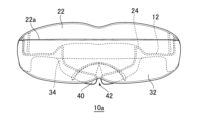
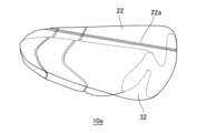
- FIG. 5 shows a mouthpiece 10a according to the first embodiment of the present invention. Portions having the same configuration as the mouthpiece 10 are given the same reference numerals as the mouthpiece 10.
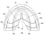
- the mouthpiece 10a includes a tongue rest 40. As shown in FIGS. 6, 7, and 9, the tongue rest 40 extends from the lower inner wall 34 of the base 12 to a position corresponding to the end of the base 12 or the first molar. It is provided so as to extend inward and toward the lower jaw.
- the tongue rest part 40 is formed to have a groove 42 (see also FIGS. 5 and 10) in the center, and is U-shaped in the same direction as the base part 12.
- the tongue rest part 40 includes first tongue rest cutting guide parts 46a, 46b corresponding to the first cutting guide parts 26a, 26b, 36a, 36b, and a second cutting guide part 46a, 46b.
- Second tongue rest cutting guide portions 48a, 48b are formed corresponding to the guide portions 28a, 28b, 38a, 38b.
- the first tongue rest cutting guide parts 46a, 46b and the second tongue rest cutting guide parts 48a, 48b are the first cutting guide parts 26a, 26b, 36a, 36b and the second cutting guide parts 28a, 28b, 38a, 38b. (See FIGS. 6 and 8.)
- the first tongue rest cutting guide parts 46a, 46b and the second tongue rest cutting guide parts 48a, 48b can also be provided on the bottom side, as shown in FIG.
- the mouthpiece 10a includes the tongue rest 40, when the user's tongue rests on the tongue rest 40, the tip of the tongue easily hits the hard palate, thereby preventing and improving a low tongue and snoring. can be connected to.
- the tongue rest part 40 is provided with the groove 42, the genioglossus muscle is unlikely to interfere with it.
- the tongue rest part 40 includes the first tongue rest cutting guide parts 46a, 46b and the second tongue rest cutting guide parts 48a, 48b, the mouthpiece 10a can be connected to the first and second cutting guide parts 26a, 48b.
- the mouthpiece 10a can be used continuously for a lifetime.
- the tongue rest part 40 can be configured such that its thickness gradually increases from the end of the base part 12 or the position corresponding to the first molar toward the central incisor (Figs. 6 and 7). , 9). With this configuration, the mouthpiece 10a can be made such that the tip of the tongue contacts the hard palate more easily.
- the groove 42 may be expanded toward the end of the base 12, or the first tongue rest cutting guide 46a, 46b and/or the second tongue rest cutting guide may be
- the guide parts 48a, 48b are configured to be inclined toward the central incisors, making it easier to cut along the first tongue rest cutting guide parts 46a, 46b and/or the second tongue rest cutting guide parts 48a, 48b. For example, it is possible to create a mouthpiece with which the genioglossus muscle is less likely to interfere.
- the mouthpiece 10a has an upper outer wall upper cutting guide portion 22a formed on the upper outer wall 22 along the U-shape of the base 12.
- the upper outer wall upper cutting guide part 22a can be formed such that the range above the upper outer wall upper cutting guide part 22a becomes larger toward the central incisor. If the configuration includes the upper outer wall upper cutting guide part 22a, it is easy to cut the upper part of the upper outer wall 22 along the upper outer wall upper cutting guide part 22a, so it is easy to cut the upper part of the upper outer wall 22, so it is easy to cut the upper part of the upper outer wall 22.
- the mouthpiece 10a can be easily worn even when the user is wearing the mouthpiece.
- FIG. 11 shows a mouthpiece 10b according to a second embodiment of the present invention.
- the basic configuration of mouthpiece 10b is the same as mouthpiece 10a, so the differences will be explained below.
- the mass piece 10b includes a U-shaped cutting guide 44 on the tongue rest 40 along the base 12 (see FIGS. 5 and 10). Although illustration and explanation are omitted, the U-shaped cutting guide portion 44 can also be provided on the bottom side. If the configuration includes the U-shaped cutting guide part 44, the tongue rest part 40 can be easily cut along the U-shaped cutting guide part 44, so that the mouthpiece 10b can be made that is unlikely to interfere with bone prominences or the like. .
- the first tongue rest cutting guide parts 46a and 46b, the second tongue rest cutting guide parts 48a and 48b, and the U-shaped cutting guide part 44 are concave grooves. . These may be grooves, protrusions, protrusions, holes (including those provided continuously), or printed lines or broken lines. Moreover, the first tongue rest cutting guide parts 46a, 46b and the second tongue rest cutting guide parts 48a, 48b may be linear or curved.
- the mouthpieces 10a, 10b of the present invention can obtain the following benefits. First, since the mouthpieces 10a and 10b of the same type can be manufactured at a relatively low cost and can be used continuously for a lifetime, there is no need to custom-make a mouthpiece according to the user's dentition, which is economical. be. Next, by preventing the jaw from moving in the downward direction when lying on the back, it is possible to prevent the position of the mandibular condyle from shifting relative to the skull, particularly the mandibular fossa.
- Underdevelopment of the maxillary sinus is considered to be a cause of incisal occlusion and reverse occlusion (socket), so by continuing to use the mouthpieces 10a and 10b from childhood, the development of incisal occlusion and reverse occlusion can be suppressed.
- tooth wear is thought to be a contributing factor to the aging of the mouth, such as narrowing of the mouth and wrinkles around the mouth, including nasolabial folds. Therefore, by interposing a mouthpiece between the teeth of the upper jaw and the lower jaw, it is possible to prevent tooth wear due to friction between the teeth, and thus it is also possible to suppress aging of the mouth area.
Landscapes
- Health & Medical Sciences (AREA)
- Life Sciences & Earth Sciences (AREA)
- Animal Behavior & Ethology (AREA)
- General Health & Medical Sciences (AREA)
- Public Health (AREA)
- Veterinary Medicine (AREA)
- Oral & Maxillofacial Surgery (AREA)
- Dentistry (AREA)
- Epidemiology (AREA)
- Pulmonology (AREA)
- Otolaryngology (AREA)
- Nursing (AREA)
- Orthopedic Medicine & Surgery (AREA)
- Engineering & Computer Science (AREA)
- Biomedical Technology (AREA)
- Heart & Thoracic Surgery (AREA)
- Vascular Medicine (AREA)
- Orthopedics, Nursing, And Contraception (AREA)
- Dental Tools And Instruments Or Auxiliary Dental Instruments (AREA)
- Dental Preparations (AREA)
Priority Applications (3)
| Application Number | Priority Date | Filing Date | Title |
|---|---|---|---|
| JP2022547316A JP7299452B1 (ja) | 2022-03-31 | 2022-03-31 | マウスピース |
| PCT/JP2022/016957 WO2023188415A1 (ja) | 2022-03-31 | 2022-03-31 | マウスピース |
| TW111131265A TW202339690A (zh) | 2022-03-31 | 2022-08-19 | 牙套 |
Applications Claiming Priority (1)
| Application Number | Priority Date | Filing Date | Title |
|---|---|---|---|
| PCT/JP2022/016957 WO2023188415A1 (ja) | 2022-03-31 | 2022-03-31 | マウスピース |
Publications (1)
| Publication Number | Publication Date |
|---|---|
| WO2023188415A1 true WO2023188415A1 (ja) | 2023-10-05 |
Family
ID=86900686
Family Applications (1)
| Application Number | Title | Priority Date | Filing Date |
|---|---|---|---|
| PCT/JP2022/016957 Ceased WO2023188415A1 (ja) | 2022-03-31 | 2022-03-31 | マウスピース |
Country Status (3)
| Country | Link |
|---|---|
| JP (1) | JP7299452B1 (https=) |
| TW (1) | TW202339690A (https=) |
| WO (1) | WO2023188415A1 (https=) |
Citations (3)
| Publication number | Priority date | Publication date | Assignee | Title |
|---|---|---|---|---|
| JP2014023672A (ja) * | 2012-07-26 | 2014-02-06 | Atsushi Otsuka | 歯科矯正装置 |
| WO2016191826A1 (en) * | 2015-06-04 | 2016-12-08 | Nowtray Pty Ltd | Dental trays or mouthguards |
| WO2020089796A1 (en) * | 2018-10-29 | 2020-05-07 | Montefarmaco Otc S.P.A. | Kit for a self-modellable and customisable device for teeth and mouth and method for using the kit for self-modelling and customising a device for teeth and mouth |
Family Cites Families (3)
| Publication number | Priority date | Publication date | Assignee | Title |
|---|---|---|---|---|
| US3878610A (en) * | 1973-11-19 | 1975-04-22 | William Alfred Coscina | Low profile dental impression tray and set of such trays |
| US20050106529A1 (en) * | 2003-11-19 | 2005-05-19 | Align Technology, Inc. | Dental impression tray with detachable portions |
| US20200170761A1 (en) * | 2017-08-24 | 2020-06-04 | Sebastian Linzen | Prefabricated Dental Impression Tray in a Modular System |
-
2022
- 2022-03-31 WO PCT/JP2022/016957 patent/WO2023188415A1/ja not_active Ceased
- 2022-03-31 JP JP2022547316A patent/JP7299452B1/ja active Active
- 2022-08-19 TW TW111131265A patent/TW202339690A/zh unknown
Patent Citations (3)
| Publication number | Priority date | Publication date | Assignee | Title |
|---|---|---|---|---|
| JP2014023672A (ja) * | 2012-07-26 | 2014-02-06 | Atsushi Otsuka | 歯科矯正装置 |
| WO2016191826A1 (en) * | 2015-06-04 | 2016-12-08 | Nowtray Pty Ltd | Dental trays or mouthguards |
| WO2020089796A1 (en) * | 2018-10-29 | 2020-05-07 | Montefarmaco Otc S.P.A. | Kit for a self-modellable and customisable device for teeth and mouth and method for using the kit for self-modelling and customising a device for teeth and mouth |
Also Published As
| Publication number | Publication date |
|---|---|
| JPWO2023188415A1 (https=) | 2023-10-05 |
| TW202339690A (zh) | 2023-10-16 |
| JP7299452B1 (ja) | 2023-06-28 |
Similar Documents
| Publication | Publication Date | Title |
|---|---|---|
| US11504213B2 (en) | Anterior guidance package, kit, and constructing method thereof | |
| JP4936061B2 (ja) | 口腔内装置及びその製造方法 | |
| KR102202863B1 (ko) | 악정형 기능을 겸비한 치아 교정장치 | |
| KR20190067743A (ko) | 하악치아 고정형 구강장치 | |
| US11833008B1 (en) | Dental appliance and method for adjusting and holding the position of a user's jaw to a relaxed position of the jaw | |
| US20140060549A1 (en) | Pre-fabricated anterior guidance package kit for patients having bruxism/clenching habit with or without various malocclusions | |
| JP2010508131A (ja) | 下顎前進装置 | |
| CN106456354B (zh) | 用于治疗睡眠呼吸暂停症的口腔矫治器 | |
| CN215458810U (zh) | 齿列矫正牙套 | |
| EP3923876B1 (en) | Dental appliance | |
| CN216221740U (zh) | 一种具有弧面导板的壳状矫治器 | |
| KR20160079302A (ko) | 턱관절 교정 장치 | |
| CN108451657A (zh) | 一种个性化功能矫治器及其制作方法 | |
| WO2024222548A1 (zh) | 牙科矫治器、矫治系统及其设计方法 | |
| JP7299452B1 (ja) | マウスピース | |
| CN213047390U (zh) | 一种护垫式前牙反牙合矫治器 | |
| CN211834785U (zh) | 一种用于正畸过程中佩戴的牙合垫 | |
| JP6120780B2 (ja) | 口腔装置 | |
| JP3210257U (ja) | 食いしばり防止装置 | |
| CN222467142U (zh) | 一种3d防吐舌舌栅 | |
| CN222265420U (zh) | 一种带有下唇挡的头帽肌激动矫治器 | |
| CN219397836U (zh) | 一种导下颌向前的齿用装置 | |
| KR102566018B1 (ko) | 치아 교정용 고정장치 | |
| KR102825598B1 (ko) | 음압을 이용한 코골이 및 수면무호흡 방지 장치 | |
| JP7171158B1 (ja) | 口腔内装着装置 |
Legal Events
| Date | Code | Title | Description |
|---|---|---|---|
| WWE | Wipo information: entry into national phase |
Ref document number: 2022547316 Country of ref document: JP |
|
| 121 | Ep: the epo has been informed by wipo that ep was designated in this application |
Ref document number: 22935552 Country of ref document: EP Kind code of ref document: A1 |
|
| NENP | Non-entry into the national phase |
Ref country code: DE |
|
| 122 | Ep: pct application non-entry in european phase |
Ref document number: 22935552 Country of ref document: EP Kind code of ref document: A1 |