EP3923876B1 - Dental appliance - Google Patents
Dental appliance Download PDFInfo
- Publication number
- EP3923876B1 EP3923876B1 EP20756010.3A EP20756010A EP3923876B1 EP 3923876 B1 EP3923876 B1 EP 3923876B1 EP 20756010 A EP20756010 A EP 20756010A EP 3923876 B1 EP3923876 B1 EP 3923876B1
- Authority
- EP
- European Patent Office
- Prior art keywords
- teeth
- protrusion
- mouth guard
- protrusions
- arch
- Prior art date
- Legal status (The legal status is an assumption and is not a legal conclusion. Google has not performed a legal analysis and makes no representation as to the accuracy of the status listed.)
- Active
Links
- 210000003254 palate Anatomy 0.000 claims description 8
- 210000004513 dentition Anatomy 0.000 description 36
- 230000036346 tooth eruption Effects 0.000 description 36
- 210000004283 incisor Anatomy 0.000 description 24
- 241000282465 Canis Species 0.000 description 18
- 239000000463 material Substances 0.000 description 17
- 239000004433 Thermoplastic polyurethane Substances 0.000 description 14
- 210000003464 cuspid Anatomy 0.000 description 14
- 229920002803 thermoplastic polyurethane Polymers 0.000 description 14
- 206010006514 bruxism Diseases 0.000 description 13
- 230000007958 sleep Effects 0.000 description 10
- 210000004763 bicuspid Anatomy 0.000 description 9
- 235000013305 food Nutrition 0.000 description 8
- 238000000034 method Methods 0.000 description 8
- 210000002455 dental arch Anatomy 0.000 description 7
- 210000003205 muscle Anatomy 0.000 description 6
- 210000001738 temporomandibular joint Anatomy 0.000 description 6
- 230000001055 chewing effect Effects 0.000 description 4
- 230000000694 effects Effects 0.000 description 4
- 208000007302 Sleep Bruxism Diseases 0.000 description 3
- 208000008312 Tooth Loss Diseases 0.000 description 3
- 230000000052 comparative effect Effects 0.000 description 3
- 230000003292 diminished effect Effects 0.000 description 3
- 239000000835 fiber Substances 0.000 description 3
- 210000001847 jaw Anatomy 0.000 description 3
- 230000003239 periodontal effect Effects 0.000 description 3
- 201000001245 periodontitis Diseases 0.000 description 3
- 239000007779 soft material Substances 0.000 description 3
- 208000004371 toothache Diseases 0.000 description 3
- 208000004188 Tooth Wear Diseases 0.000 description 2
- 210000003484 anatomy Anatomy 0.000 description 2
- 210000003298 dental enamel Anatomy 0.000 description 2
- 210000004268 dentin Anatomy 0.000 description 2
- 210000004373 mandible Anatomy 0.000 description 2
- 238000012986 modification Methods 0.000 description 2
- 230000004048 modification Effects 0.000 description 2
- 206010043220 Temporomandibular joint syndrome Diseases 0.000 description 1
- 238000009835 boiling Methods 0.000 description 1
- 229940112822 chewing gum Drugs 0.000 description 1
- 235000015218 chewing gum Nutrition 0.000 description 1
- 238000010276 construction Methods 0.000 description 1
- 230000003247 decreasing effect Effects 0.000 description 1
- 208000002925 dental caries Diseases 0.000 description 1
- 230000001419 dependent effect Effects 0.000 description 1
- 230000008451 emotion Effects 0.000 description 1
- 230000007717 exclusion Effects 0.000 description 1
- 238000010438 heat treatment Methods 0.000 description 1
- 239000004615 ingredient Substances 0.000 description 1
- 208000014674 injury Diseases 0.000 description 1
- 238000004519 manufacturing process Methods 0.000 description 1
- 230000018984 mastication Effects 0.000 description 1
- 238000010077 mastication Methods 0.000 description 1
- 210000002050 maxilla Anatomy 0.000 description 1
- 230000003278 mimic effect Effects 0.000 description 1
- 208000028169 periodontal disease Diseases 0.000 description 1
- 210000002379 periodontal ligament Anatomy 0.000 description 1
- 230000002265 prevention Effects 0.000 description 1
- 230000002035 prolonged effect Effects 0.000 description 1
- 230000000717 retained effect Effects 0.000 description 1
- 241000894007 species Species 0.000 description 1
- 208000024891 symptom Diseases 0.000 description 1
- 230000008733 trauma Effects 0.000 description 1
- XLYOFNOQVPJJNP-UHFFFAOYSA-N water Substances O XLYOFNOQVPJJNP-UHFFFAOYSA-N 0.000 description 1
Images


Classifications
-
- A—HUMAN NECESSITIES
- A61—MEDICAL OR VETERINARY SCIENCE; HYGIENE
- A61F—FILTERS IMPLANTABLE INTO BLOOD VESSELS; PROSTHESES; DEVICES PROVIDING PATENCY TO, OR PREVENTING COLLAPSING OF, TUBULAR STRUCTURES OF THE BODY, e.g. STENTS; ORTHOPAEDIC, NURSING OR CONTRACEPTIVE DEVICES; FOMENTATION; TREATMENT OR PROTECTION OF EYES OR EARS; BANDAGES, DRESSINGS OR ABSORBENT PADS; FIRST-AID KITS
- A61F5/00—Orthopaedic methods or devices for non-surgical treatment of bones or joints; Nursing devices; Anti-rape devices
- A61F5/56—Devices for preventing snoring
- A61F5/566—Intra-oral devices
-
- A—HUMAN NECESSITIES
- A63—SPORTS; GAMES; AMUSEMENTS
- A63B—APPARATUS FOR PHYSICAL TRAINING, GYMNASTICS, SWIMMING, CLIMBING, OR FENCING; BALL GAMES; TRAINING EQUIPMENT
- A63B71/00—Games or sports accessories not covered in groups A63B1/00 - A63B69/00
- A63B71/08—Body-protectors for players or sportsmen, i.e. body-protecting accessories affording protection of body parts against blows or collisions
- A63B71/085—Mouth or teeth protectors
-
- A—HUMAN NECESSITIES
- A61—MEDICAL OR VETERINARY SCIENCE; HYGIENE
- A61C—DENTISTRY; APPARATUS OR METHODS FOR ORAL OR DENTAL HYGIENE
- A61C7/00—Orthodontics, i.e. obtaining or maintaining the desired position of teeth, e.g. by straightening, evening, regulating, separating, or by correcting malocclusions
- A61C7/08—Mouthpiece-type retainers or positioners, e.g. for both the lower and upper arch
-
- A—HUMAN NECESSITIES
- A61—MEDICAL OR VETERINARY SCIENCE; HYGIENE
- A61F—FILTERS IMPLANTABLE INTO BLOOD VESSELS; PROSTHESES; DEVICES PROVIDING PATENCY TO, OR PREVENTING COLLAPSING OF, TUBULAR STRUCTURES OF THE BODY, e.g. STENTS; ORTHOPAEDIC, NURSING OR CONTRACEPTIVE DEVICES; FOMENTATION; TREATMENT OR PROTECTION OF EYES OR EARS; BANDAGES, DRESSINGS OR ABSORBENT PADS; FIRST-AID KITS
- A61F5/00—Orthopaedic methods or devices for non-surgical treatment of bones or joints; Nursing devices; Anti-rape devices
- A61F5/56—Devices for preventing snoring
- A61F2005/563—Anti-bruxisme
Definitions
- the present invention relates generally to mouth guards. More particularly, the present invention relates to a mouth guard for reducing tooth damage during sleep.
- a mandibular arch i.e., the arch of teeth along the mandible (commonly referred to as the lower jaw) or lower arch
- a maxillary arch i.e., the arch of teeth along the maxilla (commonly referred to as the upper jaw) or upper arch
- Teeth along the mandibular or lower arch are commonly referred to as 'the lower teeth
- teeth along the maxillary arch or upper arch are commonly referred to as 'the upper teeth.
- Bruxism is excessive teeth grinding or jaw clenching.
- one or more lower teeth come into contact with one or more upper teeth as food is masticated (i.e., chewed).
- food is disposed between only a few of the lower and upper teeth.
- People chewing their food tend to focus on grinding the food with just those particular teeth where the food is located, and avoid needlessly grinding their other teeth together in those places where there is no food to chew.
- some people grind or clench their teeth at times other than when chewing food.
- Bruxism is excessive teeth grinding or jaw clenching, and it can occur during sleep.
- nocturnal bruxism Bruxism during sleep is referred to as nocturnal bruxism. While the cause of nocturnal bruxism is not completely understood, it is likely due to various factors including, but not limited to, personality, stress, and emotion. The majority of people with nocturnal bruxism do not make noises while grinding or clenching their teeth during sleep. However, there are a number of people who do create noises (e.g., screeching noises) from grinding or clenching their teeth during sleep.
- noises e.g., screeching noises
- Tooth wear caused by bruxism affects the occlusal surfaces (i.e., the biting surfaces) of the teeth.
- the exact location and pattern of tooth wear depends on how the bruxism occurs (e.g., when the canines and incisors of the opposing mandibular and maxillary arches are moved against each other laterally, this can lead to the wearing down of the incisal edges of the teeth.
- People with bruxism may grind their anterior teeth (i.e., front teeth) and may also grind their posterior teeth (i.e., back teeth).
- Adult anterior teeth include the central and lateral incisors and the canine teeth, and make up the six upper and six lower front teeth.
- Adult posterior teeth include three molars and two premolars (or bicuspids) and make up the ten upper and ten lower back teeth.
- This grinding and clenching of teeth can apply large amounts of force on those teeth being clenched or ground together.
- the force of this grinding and clenching of teeth can wear away the enamel layer of one or more teeth, and expose the dentin layer of these teeth to the grinding and clenching.
- the dentin layer is softer and more vulnerable to wear and tooth decay than the enamel layer. If enough of the tooth is worn away or decayed, the tooth will effectively be weakened, and may fracture under the increased forces that occur in bruxism.
- This grinding and clenching can subsequently cause various oral health issues including, but not limited to, toothaches, cavities, periodontitis, and tooth loss.
- This lateral force will cause this particular tooth to shift left and right due to the opposing tooth being stronger and unloading force that is far greater than the amount of force this particular tooth can bear.
- the person can experience various symptoms as a result of the grinding and clenching that include, but are not limited to, toothaches, cavities, periodontitis, and tooth loss.
- the apparatus for preventing bruxism comprises: a body part formed with a tooth groove to be fitted in any one of a mandibular anterior tooth part or a maxillary anterior tooth part made up of an incisal tooth, a lateral incisor tooth, a canine tooth; and a contact part formed at any one portion of the front surface or the rear surface of the body part, wherein the contact part is formed on the front surface of the body part and is in contact with the tongue side surface of the maxillary anterior tooth part when the body part is fitted to the mandibular anterior tooth part, and the contact part is formed on the rear part of the body part and is in contact with the outer surface of the mandibular anterior tooth part when the body part is fitted to the maxillary anterior tooth part.
- US 2014/0109919 A1 describes an intraoral discluding appliance for the prevention of trauma and temporomandibular joint syndrome.
- the device includes two discluding elements over the cuspid areas known as cuspid pads.
- the device is inserted in the mouth and retained against the upper or lower anterior teeth. As the mouth is closed, the discluding elements contact the opposing cuspids and prevent the posterior teeth from touching.
- an embodiment of the present invention resides in a mouth guard assembly 20 including a mouth guard tray 30 for teeth of a user's upper dental arch (i.e., an upper guard tray 30), and a mouth guard tray 40 for teeth of a user's lower dental arch (i.e., a lower guard tray 40).
- Each guard tray 30, 40 is fabricated using thermoplastic polyurethane (TPU) material.
- TPU thermoplastic polyurethane
- An example of TPU material used to form the guard trays 30, 40 is CLEARSPLINT from Astron Dental ( https://www.astrondental.com/ ).
- the TPU material may be optically clear (i.e., generally transparent), translucent, or opaque.
- the TPU material may be colored or uncolored.
- Both mouth guard trays 30, 40 can be worn at the same time. Alternatively, just one of the mouth guard trays 30, 40 can be worn.
- the upper guard tray 30 can be worn on the upper arch with no mouth guard tray on the lower arch (or the lower guard tray 40 can be worn on the lower arch with no mouth guard tray on the upper arch). If worn on both dental arches or just one of the dental arches, the result will be that the teeth on both arches will be protected. If a mouth guard tray is worn on just one arch, the mouth guard tray will be designed to cover all existing teeth on that arch. The number of teeth covered will depend on the unique dentition of each individual patient.
- the mouth guards 30, 40 extend from incisors at a front of the mouth back towards, and generally covering, at least one of the premolars on each side of the patient's mouth. It is preferable that all teeth be covered by the mouth guards 30, 40 in order to distribute the grinding force. Coverage of the molars, for example, can reduce the possibility of supra-eruption of one or more of a patient's molars, especially if a patient is missing a molar on one of their dental arches that would normally oppose a molar on the other dental arch. How far back the mouth guard tray 30, 40 extends can vary from patient-to-patient, as each individual patient's dentition is unique.
- Each of the mouth guards 30, 40 is designed to include a pair of protrusions 32, 42 that will generally cover an area over the user's canine teeth, but can also generally cover a lateral area extending between the user's lateral incisor, canine, and first premolar teeth. Due to the uniqueness of each individual, the protrusions 32, 42, may generally cover an area over portions of the user's lateral incisor and canine teeth, an area generally over the user's canine teeth, and an area generally over the user's canine and first premolar teeth.
- Placement of the protrusions 32, 42, over just the anterior teeth should be avoided as anterior teeth like the incisors have shorter roots and less periodontal ligament which makes them not as strong as the canine teeth and more vulnerable to the grinding forces. If the protrusions 32, 42 are placed over just anterior teeth such as the central incisors or lateral incisors, the force from grinding could cause these particular anterior teeth to shift outward and be more protrusive. Once the central incisors or lateral incisors are protrusive, gaps can form between the lateral incisors and the canines, and this can result in the incisors being more at risk of periodontal disease.
- the protrusions 32 are configured to engage the canine or first premolar teeth of the mandibular arch; and the protrusions 32 grind against the mandibular canine or premolar tooth during a lateral excursion which is the motion when the mandible or lower jaw moves generally laterally (i.e., generally left and right) during grinding movement.
- the maxillary canines (or upper canines) are preferable over the other teeth is because the canines have the longest roots and can withstand the force of grinding.
- the canine teeth are located the most distal from the temporomandibular joint (TMJ) as compared to the molars or premolars.
- the protrusions 32, 42 have a generally fang-like appearance.
- the protrusions 32, 42 can be shaped as desired to accommodate a particular user's unique dentition.
- the lower portion of the protrusions 32 can have a flat-shaped bottom portion rather than a sharp fang-like bottom portion according to the invention.
- the upper portion of the protrusions 42 can have a flat-shaped top portion rather than a 'sharp' fang-like top portion according to the invention.
- the flat-shaped bottom portion of the protrusions of the upper tray 30 can still function as the grinding contact point against the mandibular canines and be just as effective as the 'sharp' fang-like bottom portion of the protrusions 32.
- flat-shaped top portion of the protrusions of the lower tray 40 still able to function as the grinding contact point against the maxillary canines and be just as effective as the 'sharp' fang-like top portion of the protrusions 42.
- the angle of the slope of the protrusions 32, 42 also varies from zero (0) degrees of a flat top to as much as seventy-five (75) degrees that mimics the anatomy of a canine. This angle is determined by the lateral movement of the jaw and hence the mandibular anterior teeth and posterior teeth do not come into contact with the maxillary mouth guard 30 during the grinding movement.
- the length of the protrusions 32, 42 varies from person-to-person from five millimeters to twenty millimeters (5 mm to 20 mm) but the most optimal length is generally ten millimeters (10 mm).
- the lower posterior teeth such as the mandibular second premolars and the molars
- the protrusion 32 may fracture during grinding.
- the other areas of the mouth guard 30 have to be thin to avoid contact with the mandibular teeth to prevent damage to the anterior teeth and the posterior teeth.
- the protrusions 32, 42 are generally ten millimeters (10 mm) thick along a longitudinal length from a coronal portion of the dentition to a coronal portion of the protrusion 32, 42.
- the protrusion 32 can be generally ten millimeters (10 mm) long from the tip of one of the user's teeth (e.g., canine tooth) 36 on the maxillary arch
- the protrusion 42 can be generally ten millimeters (10 mm) long from the tip of one of the user's teeth (e.g., lateral incisor) 46 on the mandibular arch, with sloped portions of the protrusions 32, 42 deflecting each other.
- the protrusions 32, 42 of the mouth guards 30, 40 can be seen contacting each other along their respective ten millimeter (10 mm) lengths.
- the protrusions 32, 42 may contact each other or other portions of their opposing mouth guards at any number of places.
- Figure 11 an example shows the patient wearing only a lower mouth guard tray 40, with the protrusion 42 being generally ten millimeters (10 mm) long from the tip of one of the user's teeth (e.g., lateral incisor) 46 on the mandibular arch, and the protrusion 42 contacting one of the user's teeth (e.g., canine tooth) 36 on the maxillary arch.
- an example shows the patient wearing only an upper mouth guard tray 30, with the protrusion 32 being generally ten millimeters (10 mm) long from the tip of one of the user's teeth (e.g., canine) 36 on the maxillary arch, and the protrusion 32 contacting one of the user's teeth (e.g., lateral incisor) 46 on the mandibular arch.
- Ten millimeters (10 mm) is about the minimum distance necessary between the maxillary and mandibular dentitions.
- Two millimeters (2 mm) is about the minimum thickness T1 of the material of the upper mouth guard tray 30 between the central incisor and a bottom side of the upper mouth guard tray 30 that contacts the lower mouth guard tray 40.
- the thickness T1 of the upper mouth guard tray 30 between the central incisor and the bottom side of the upper mouth guard tray 30 can vary from individual-to-individual.
- two millimeters (2 mm) is about the minimum thickness T2 of the material of the lower mouth guard tray 40 between the central incisor and a top side of the lower mouth guard tray 40 that contacts the upper mouth guard tray 30.
- the thickness T2 of the lower mouth guard tray 40 between the central incisor and the top side of the lower mouth guard tray 40 can vary from individual-to-individual.
- the anterior and posterior dentition area on the mouth guard trays 30, 40 will be minimal where opposing dentition will not come into contact with these two areas.
- Each protrusion 32, 42 includes a curved slope on a palate side of the protrusion 32, 42 that creates a gap between the upper and lower dentition when the user is grinding generally laterally (i.e., sideways).
- Each protrusion 32, 42 includes a curved slope on a labial side of the protrusion 32, 42. In the alternative, the slopes on the palate and labial sides of the protrusions 32, 42 may angular, or a combination of angular and curved.
- the shape of the protrusions 32, 42 generally mimic the anatomy of a canine tooth, but the slopes on the palate and labial sides of the protrusions 32, 42 may be shaped as needed in order to accommodate the unique dentition of a particular user.
- the protrusions 32, 42 prevent the anterior teeth and molars from coming into contact during lateral excursions caused by grinding by guiding the guard trays 30, 40 away from each other and cushioning contact between the guard trays 30, 40. Wherever the guard trays 30, 40 come into contact, the TPU material provides cushioning and dissipation of the grinding force.
- the protrusions 32, 42 will cause the distance between the anterior and posterior maxillary and mandibular teeth to increase. Because of this increase, the anterior and posterior teeth will not be in direct contact and, hence, the force exerted on these teeth will be diminished; prolonging the life of these teeth. As for the canines and premolars covered by the protrusions 32, 42s, the ten millimeter (10 mm) thickness will also lessen the force applied directly to these teeth. As the distance between both arches increases, the effect of the force exerted by muscles in the user's head, neck, and shoulder will be diminished.
- the canine teeth are the longest teeth in both arches of dentitions and the canines also have more periodontal fibers which can tolerate more force than can be tolerated by the anterior incisors during grinding.
- the force on the molars from grinding is many times more than the force on the canines, premolars, and incisors, because the molars are closer to the temporomandibular (TMJ) joint.
- a first method for fabricating the upper and lower guards 30, 40 is for a dentist or other dental professional to take impressions of the patient's upper and lower arches of dentition, as well as a bite registration, and then send them to a dental laboratory.
- an impression can be taken of just one of the arches of dentition if it is determined that a mouth guard is required for only one of the arches of dentition.
- models of the patient's upper and lower arches of dentition are made from the impressions.
- a technician at the dental laboratory then heats up a sheet of TPU material with a heating machine to make a guard tray.
- This sheet of TPU material softens and can be formed around a selected one of the models of the patient's dentition (e.g., the upper arch of dentition). While the material is still soft, the technician cuts and shapes the material to forms the upper mouth guard tray 30 and protrusions 32. This process is repeated to create the lower mouth guard tray 40 and protrusions 42.
- the protrusions 32, 42 are shaped such that each protrusion 32, 42 is sloped on palate and labial sides of the maxillary and mandibular arches. As the dentition of each individual is unique, the protrusions 32, 42 are sloped to meet the unique needs of each individual.
- the technician would use the models of the patient's upper and lower arches of dentition to generally match the slope of the protrusions 32, 42 to the natural slope(s) of the patient's canines, incisors and/or bicuspids. Again, the unique nature of each individual's dentition is taken into account.
- An upper rim 34 of the upper mouth guard tray 30 should extend at least halfway up the coronal portion of the teeth but should not extend above the patient's gumline.
- a lower rim 44 of the lower mouth guard tray 40 should extend at least halfway down the coronal portion of the teeth but should not extend below the patient's gumline.
- guard trays 30, 40 can be created by a digital impression of a patient's dentition being taken, and then using the CAD/CAM machine to form the guard trays 30, 40.
- the TPU material of the mouth guard trays 30, 40 is hard enough to prevent contact between the upper and lower dentitions as the guards 30, 40 come into contact with each other when grinding starts. Sometimes an individual sleeps with their mouth open, and their upper and lower dentition will come into contact when grinding starts. For example, once the mouth guard trays 30, 40 and dentitions come into contact, the hardness of the TPU material of the mouth guard trays 30, 40 prevents the opposing dentitions from coming into direct contact, and decreasing the effect of the grinding or clenching force from muscles in the patient's head, neck, and/or shoulders.
- a soft material i.e., a material softer than TPU
- the soft material is no more effective than a stick of well-chewed chewing gum at dissipating the force on one or more teeth from the contact of opposing dentition during grinding and clenching.
- a user places the mouth guard trays 30, 40 on the lower and upper arches of their mouth prior to going to sleep at night.
- the protrusions 32, 42 will also cause the anterior dentitions on both the upper and lower arches not to directly contact which would alleviate the forces caused by grinding or clenching.
- each mouth guard tray 30, 40 can be used at the same time.
- each mouth guard tray 30, 40 can be used without the other.
- the function of each mouth guard tray 30, 40 is unchanged if used alone ortogether (although the number of covered teeth may vary due to the unique nature of each individual's dentition).
- opposite refers to the opposing arch which is not covered by the mouth guard tray 30, 40.
- opposing arch refers to the mandibular arch when the upper guard tray 30 is placed over teeth of the maxillary arch.
- opposite arch refers to the maxillary arch when the lower guard tray 40 is placed over teeth of the mandibular arch.
- the present invention has been discussed above in connection with use in a human mouth, the present invention is not limited to that environment and may also be used in the mouths of other species.
- Spatially relative terms such as “front,” “rear,” “left,” “right,” “inner,” “outer,” “beneath”, “below”, “lower”, “above”, “upper,” “horizontal,” “vertical” and the like, may be used herein for ease of description to describe one element or feature's relationship to another element(s) or feature(s) as illustrated in the figures.
- Spatially relative terms may be intended to encompass different orientations of the device in use or operation in addition to the orientation depicted in the figures. For example, if the device in the figures is turned over, elements described as “below” or “beneath” other elements or features would then be oriented “above” the other elements or features. Thus, the example term “below” can encompass both an orientation of above and below.
- the device may be otherwise oriented (rotated 90 degrees or at other orientations) and the spatially relative descriptors used herein interpreted accordingly.
Description
- The present invention relates generally to mouth guards. More particularly, the present invention relates to a mouth guard for reducing tooth damage during sleep.
- In humans, there are two dental arches: a mandibular arch (i.e., the arch of teeth along the mandible (commonly referred to as the lower jaw) or lower arch) and a maxillary arch (i.e., the arch of teeth along the maxilla (commonly referred to as the upper jaw) or upper arch). Teeth along the mandibular or lower arch are commonly referred to as 'the lower teeth,' and teeth along the maxillary arch or upper arch are commonly referred to as 'the upper teeth.'
- Bruxism is excessive teeth grinding or jaw clenching. During the normal process of mastication (i.e., chewing food), one or more lower teeth come into contact with one or more upper teeth as food is masticated (i.e., chewed). Generally, during chewing, food is disposed between only a few of the lower and upper teeth. People chewing their food tend to focus on grinding the food with just those particular teeth where the food is located, and avoid needlessly grinding their other teeth together in those places where there is no food to chew. However, some people grind or clench their teeth at times other than when chewing food. Bruxism is excessive teeth grinding or jaw clenching, and it can occur during sleep. Bruxism during sleep is referred to as nocturnal bruxism. While the cause of nocturnal bruxism is not completely understood, it is likely due to various factors including, but not limited to, personality, stress, and emotion. The majority of people with nocturnal bruxism do not make noises while grinding or clenching their teeth during sleep. However, there are a number of people who do create noises (e.g., screeching noises) from grinding or clenching their teeth during sleep.
- Tooth wear caused by bruxism affects the occlusal surfaces (i.e., the biting surfaces) of the teeth. The exact location and pattern of tooth wear depends on how the bruxism occurs (e.g., when the canines and incisors of the opposing mandibular and maxillary arches are moved against each other laterally, this can lead to the wearing down of the incisal edges of the teeth. People with bruxism may grind their anterior teeth (i.e., front teeth) and may also grind their posterior teeth (i.e., back teeth). Adult anterior teeth include the central and lateral incisors and the canine teeth, and make up the six upper and six lower front teeth. Adult posterior teeth include three molars and two premolars (or bicuspids) and make up the ten upper and ten lower back teeth. This grinding and clenching of teeth can apply large amounts of force on those teeth being clenched or ground together. The force of this grinding and clenching of teeth can wear away the enamel layer of one or more teeth, and expose the dentin layer of these teeth to the grinding and clenching. The dentin layer is softer and more vulnerable to wear and tooth decay than the enamel layer. If enough of the tooth is worn away or decayed, the tooth will effectively be weakened, and may fracture under the increased forces that occur in bruxism. This grinding and clenching can subsequently cause various oral health issues including, but not limited to, toothaches, cavities, periodontitis, and tooth loss.
- When a person has stress and goes to sleep, that person can unconsciously use their head, neck, and shoulder muscles to contract their lower jaw so that one or more of their lower teeth (i.e., one or more teeth of the mandibular arch) come into contact with one or more of their upper teeth (i.e., one or more teeth of the maxillary arch) as their lower jaw moves in lateral and protrusive directions relative to their mouth. This, in turn, will cause lateral forces on that person's upper and lower teeth. One tooth is usually the weakest link due to the tremendous amount of lateral force applied to this particular tooth by an opposing tooth. This lateral force will cause this particular tooth to shift left and right due to the opposing tooth being stronger and unloading force that is far greater than the amount of force this particular tooth can bear. After many nights of this force being applied to this tooth particular from grinding, the person can experience various symptoms as a result of the grinding and clenching that include, but are not limited to, toothaches, cavities, periodontitis, and tooth loss.
- Different types of dental appliances (e.g., mouth guards) have been proposed to protect teeth from the effects of bruxism. However, such dental appliances have their limitations and can always be improved.
-
KR 2018 0116089 A -
DE 20 2004 020 196 U1 describes an upper jaw bite rail with a receiving region for upper jaw teeth and with an underside directed towards the lower jaw teeth in the inserted state of the bite rail, wherein a plateau extends on the underside of the bite rail in the front tooth region and wherein the receiving region is designed in such a way that the plateau encloses an angle in the range of 0° and 10° with the occlusal plane in the inserted state of the bite rail and is inclined rearward at an angle > 0°. -
US 2014/0109919 A1 describes an intraoral discluding appliance for the prevention of trauma and temporomandibular joint syndrome. The device includes two discluding elements over the cuspid areas known as cuspid pads. The device is inserted in the mouth and retained against the upper or lower anterior teeth. As the mouth is closed, the discluding elements contact the opposing cuspids and prevent the posterior teeth from touching. - Accordingly, there is a need for an improved dental appliance in the form of a mouth guard. There is also a need for a mouth guard that protects teeth from the effects of bruxism during sleep. There is an additional need for a mouth guard that is easier to manufacture, assemble, adjust, and maintain. The present invention satisfies these needs and provides other related advantages.
- The invention is defined by the independent claims, while preferred embodiments form the subject of the dependent claims.
- Other features and advantages of the present invention will become apparent from the following more detailed description, taken in conjunction with the accompanying drawings, which illustrate, by way of example, the principles of the invention.
- The various present embodiments now will be discussed in detail with an emphasis on highlighting the advantageous features with reference to the drawings of various embodiments. The illustrated embodiments are intended to illustrate, but not to limit the invention. These drawings include the following figures, in which like numerals indicate like parts:
-
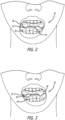
FIGURE 1 illustrates a front view of a user's open mouth, with an upper mouth guard tray covering a least a portion of the user's upper teeth and a lower mouth guard tray covering at least a portion of the user's lower teeth, in accordance with an embodiment of the present invention; -
FIGURE 2 illustrates the upper and lower mouth guard trays ofFIGURE 1 , with the user's lower jaw moved laterally to the user's right as the user grinds their teeth; -
FIGURE 3 illustrates the upper and lower mouth guard trays ofFIGURE 1 , with the user's lower jaw moved laterally to the user's left as the user grinds their teeth; -
FIGURE 4 illustrates the user wearing only the lower mouth guard tray ofFIGURE 1 , with the user's lower jaw moved laterally to the user's right; -
FIGURE 5 illustrates the user wearing only the upper mouth guard tray ofFIGURE 1 , with the user's lower jaw moved laterally to the user's left; -
FIGURE 6 illustrates a front, upper view of a top side of the upper mouth guard tray ofFIGURE 1 ; -
FIGURE 7 illustrates a rear, upper view of a bottom side of the upper mouth guard tray ofFIGURE 1 ; -
FIGURE 8 illustrates a front, upper view of a top side of the lower mouth guard tray ofFIGURE 1 ; -
FIGURE 9 illustrates a rear, upper view of a bottom side of the lower mouth guard tray ofFIGURE 1 ; -
FIGURE 10 illustrates a section view illustrating contact between the protrusions of the upper and lower mouth guard trays during grinding; -
FIGURE 11 illustrates a section view illustrating contact between the protrusion of the lower mouth guard tray with upper dentition during grinding; and -
FIGURE 12 illustrates a section view illustrating contact between the protrusion of the upper mouth guard tray with lower dentition during grinding. - The following detailed description describes present embodiments with reference to the drawings. In the drawings, reference numbers label elements of present embodiments. These reference numbers are reproduced below in connection with the discussion of the corresponding drawing features.
- It is to be understood that the figures and descriptions of the present invention have been simplified to illustrate elements that are relevant for a clear understanding of the present invention, while eliminating, for the purpose of clarity, many other elements found in mouth guards. Those of ordinary skill in the pertinent arts may recognize that other elements and/or steps are desirable and/or required in implementing the present invention. However, because such elements and steps are well known in the art, and because they do not facilitate a better understanding of the present invention, a discussion of such elements and steps is not provided herein. The disclosure herein is directed to all such variations and modifications to such elements and methods known to those skilled in the pertinent arts.
- As shown in
FIGS. 1-12 for purposes of illustration, an embodiment of the present invention resides in amouth guard assembly 20 including amouth guard tray 30 for teeth of a user's upper dental arch (i.e., an upper guard tray 30), and amouth guard tray 40 for teeth of a user's lower dental arch (i.e., a lower guard tray 40). Eachguard tray guard trays - Both
mouth guard trays mouth guard trays upper guard tray 30 can be worn on the upper arch with no mouth guard tray on the lower arch (or thelower guard tray 40 can be worn on the lower arch with no mouth guard tray on the upper arch). If worn on both dental arches or just one of the dental arches, the result will be that the teeth on both arches will be protected. If a mouth guard tray is worn on just one arch, the mouth guard tray will be designed to cover all existing teeth on that arch. The number of teeth covered will depend on the unique dentition of each individual patient. At a minimum, the mouth guards 30, 40 extend from incisors at a front of the mouth back towards, and generally covering, at least one of the premolars on each side of the patient's mouth. It is preferable that all teeth be covered by the mouth guards 30, 40 in order to distribute the grinding force. Coverage of the molars, for example, can reduce the possibility of supra-eruption of one or more of a patient's molars, especially if a patient is missing a molar on one of their dental arches that would normally oppose a molar on the other dental arch. How far back themouth guard tray - Each of the mouth guards 30, 40 is designed to include a pair of
protrusions protrusions protrusions protrusions - The
protrusions 32 are configured to engage the canine or first premolar teeth of the mandibular arch; and theprotrusions 32 grind against the mandibular canine or premolar tooth during a lateral excursion which is the motion when the mandible or lower jaw moves generally laterally (i.e., generally left and right) during grinding movement. The maxillary canines (or upper canines) are preferable over the other teeth is because the canines have the longest roots and can withstand the force of grinding. Also, the canine teeth are located the most distal from the temporomandibular joint (TMJ) as compared to the molars or premolars. The closer the tooth is to the TMJ, the stronger the force created by the TMJ muscles which would cause damage to the teeth. Their long root and location give the canines an advantage over the molars and premolars to withstand the force caused by the TMJ muscles during grinding or clenching. - According to the invention, the
protrusions protrusions protrusions 32 can have a flat-shaped bottom portion rather than a sharp fang-like bottom portion according to the invention. Likewise, in the comparative example for better understanding the invention that is not covered by the claims, the upper portion of theprotrusions 42 can have a flat-shaped top portion rather than a 'sharp' fang-like top portion according to the invention. The flat-shaped bottom portion of the protrusions of theupper tray 30 can still function as the grinding contact point against the mandibular canines and be just as effective as the 'sharp' fang-like bottom portion of theprotrusions 32. Likewise, with regard to flat-shaped top portion of the protrusions of thelower tray 40 still able to function as the grinding contact point against the maxillary canines and be just as effective as the 'sharp' fang-like top portion of theprotrusions 42. - The angle of the slope of the
protrusions maxillary mouth guard 30 during the grinding movement. - Due to the uniqueness of each individual's dentition, the length of the
protrusions protrusion 32 is too short, the lower posterior teeth, such as the mandibular second premolars and the molars, can still come into contact with themouth guard 30 during the lateral excursion of grinding. If theprotrusion 32 is too long, theprotrusion 32 may fracture during grinding. The other areas of themouth guard 30 have to be thin to avoid contact with the mandibular teeth to prevent damage to the anterior teeth and the posterior teeth. As seen inFigures 10-12 , theprotrusions
coronal portion of theprotrusion Figure 10 , with the patient wearing both upper and lower mouth guards 30, 40, theprotrusion 32 can be generally ten millimeters (10 mm) long from the tip of one of the user's teeth (e.g., canine tooth) 36 on the maxillary arch, and theprotrusion 42 can be generally ten millimeters (10 mm) long from the tip of one of the user's teeth (e.g., lateral incisor) 46 on the mandibular arch, with sloped portions of theprotrusions protrusions protrusions Figure 11 , an example shows the patient wearing only a lowermouth guard tray 40, with theprotrusion 42 being generally ten millimeters (10 mm) long from the tip of one of the user's teeth (e.g., lateral incisor) 46 on the mandibular arch, and theprotrusion 42 contacting one of the user's teeth (e.g., canine tooth) 36 on the maxillary arch. InFigure 12 , an example shows the patient wearing only an uppermouth guard tray 30, with theprotrusion 32 being generally ten millimeters (10 mm) long from the tip of one of the user's teeth (e.g., canine) 36 on the maxillary arch, and theprotrusion 32 contacting one of the user's teeth (e.g., lateral incisor) 46 on the mandibular arch. Ten millimeters (10 mm) is about the minimum distance necessary between the maxillary and mandibular dentitions. Two millimeters (2 mm) is about the minimum thickness T1 of the material of the uppermouth guard tray 30 between the central incisor and a bottom side of the uppermouth guard tray 30 that contacts the lowermouth guard tray 40. As each individual is unique, the thickness T1 of the uppermouth guard tray 30 between the central incisor and the bottom side of the uppermouth guard tray 30 can vary from individual-to-individual. Likewise, two millimeters (2 mm) is about the minimum thickness T2 of the material of the lowermouth guard tray 40 between the central incisor and a top side of the lowermouth guard tray 40 that contacts the uppermouth guard tray 30. As each individual is unique, the thickness T2 of the lowermouth guard tray 40 between the central incisor and the top side of the lowermouth guard tray 40 can vary from individual-to-individual. The anterior and posterior dentition area on themouth guard trays protrusions protrusion protrusion protrusion protrusion protrusions protrusions protrusions protrusions guard trays guard trays guard trays - During lateral excursions or lateral movements of the lower jaw while the user grinds their teeth during sleep, the
protrusions protrusions 32, 42s, the ten millimeter (10 mm) thickness will also lessen the force applied directly to these teeth. As the distance between both arches increases, the effect of the force exerted by muscles in the user's head, neck, and shoulder will be diminished. The canine teeth are the longest teeth in both arches of dentitions and the canines also have more periodontal fibers which can tolerate more force than can be tolerated by the anterior incisors during grinding. As for the molars in the posterior region, the force on the molars from grinding is many times more than the force on the canines, premolars, and incisors, because the molars are closer to the temporomandibular (TMJ) joint. - A first method for fabricating the upper and
lower guards mouth guard tray 30 andprotrusions 32. This process is repeated to create the lowermouth guard tray 40 andprotrusions 42. Theprotrusions protrusion protrusions protrusions upper rim 34 of the uppermouth guard tray 30 should extend at least halfway up the coronal portion of the teeth but should not extend above the patient's gumline. Likewise, alower rim 44 of the lowermouth guard tray 40 should extend at least halfway down the coronal portion of the teeth but should not extend below the patient's gumline. An alternative method is for a pre-fabricated mouth guard made of TPU material that can be softened by boiling water and shaped around the upper and lower arches of dentition. In a further alternative, if a dental CAD/CAM machine is used,guard trays guard trays - The TPU material of the
mouth guard trays guards mouth guard trays mouth guard trays mouth guard trays 30, 40 (i.e., mouth guard trays made of material softer than TPU) at first contact between the upper andlower guard trays - By wearing the
mouth guard tray - In use, a user places the
mouth guard trays protrusions - As disclosed above, the
mouth guard trays mouth guard tray mouth guard tray - Throughout the specification, it is to be understood that the term "opposing" refers to the opposing arch which is not covered by the
mouth guard tray upper guard tray 30, the term "opposing arch" refers to the mandibular arch when theupper guard tray 30 is placed over teeth of the maxillary arch. In another example, in the context of thelower guard tray 40, the term "opposing arch" refers to the maxillary arch when thelower guard tray 40 is placed over teeth of the mandibular arch. - Although the present invention has been discussed above in connection with use in a human mouth, the present invention is not limited to that environment and may also be used in the mouths of other species.
- The figures (and various components shown therein) of the specification are not to be construed as drawn to scale.
- Throughout this specification the word "comprise", or variations such as "comprises" or "comprising", will be understood to imply the inclusion of a stated element, integer or step, or group of elements, integers or steps, but not the exclusion of any other element, integer or step, or group of elements, integers or steps.
- The use of the expression "at least" or "at least one" suggests the use of one or more elements or ingredients or quantities, as the use may be in the embodiment of the disclosure to achieve one or more of the desired objects or results.
- The terminology used herein is for the purpose of describing particular example embodiments only and is not intended to be limiting. As used herein, the singular forms "a", "an" and "the" may be intended to include the plural forms as well, unless the context clearly indicates otherwise. The terms "comprises," "comprising," "including," and "having," are inclusive and therefore specify the presence of stated features, integers, steps, operations, elements, and/or components, but do not preclude the presence or addition of one or more other features, integers, steps, operations, elements, components, and/or groups thereof. The method steps, processes, and operations described herein are not to be construed as necessarily requiring their performance in the particular order discussed or illustrated, unless specifically identified as an order of performance. It is also to be understood that additional or alternative steps may be employed.
- When an element or layer is referred to as being "on", "engaged to", "connected to" or "coupled to" another element or layer, it may be directly on, engaged, connected or coupled to the other element or layer, or intervening elements or layers may be present. In contrast, when an element is referred to as being "directly on," "directly engaged to", "directly connected to" or "directly coupled to" another element or layer, there may be no intervening elements or layers present. Other words used to describe the relationship between elements should be interpreted in a like fashion (e.g., "between" versus "directly between," "adjacent" versus "directly adjacent," etc.). As used herein, the term "and/or" includes any and all combinations of one or more of the associated listed items.
- Spatially relative terms, such as "front," "rear," "left," "right," "inner," "outer," "beneath", "below", "lower", "above", "upper," "horizontal," "vertical" and the like, may be used herein for ease of description to describe one element or feature's relationship to another element(s) or feature(s) as illustrated in the figures. Spatially relative terms may be intended to encompass different orientations of the device in use or operation in addition to the orientation depicted in the figures. For example, if the device in the figures is turned over, elements described as "below" or "beneath" other elements or features would then be oriented "above" the other elements or features. Thus, the example term "below" can encompass both an orientation of above and below. The device may be otherwise oriented (rotated 90 degrees or at other orientations) and the spatially relative descriptors used herein interpreted accordingly.
- The above description presents the best mode contemplated for carrying out the present invention, and of the manner and process of making and using it, in such full, clear, concise, and exact terms as to enable any person skilled in the art to which it pertains to make and use this invention. This invention is not limited to the particular embodiments disclosed. On the contrary, this invention covers all modifications and alternate constructions coming within the scope of the invention as generally expressed by the following claims, which particularly point out and distinctly claim the subject matter of the invention.
Claims (12)
- A mouth guard, comprising:a tray (30) configured to encompass at least anterior teeth of a maxillary arch;wherein the tray (30) includes a pair of protrusions (32) extending away from the tray (30), each protrusion (32) configured to generally overlie a portion of at least two anterior teeth of the maxillary arch;whereby the protrusions (32) are configured to engage at least one tooth of a mandibular arch;whereby damage to the at least anterior teeth of the maxillary arch is reduced or prevented; characterized in that the protrusions (32) have a length from 5 mm to 20 mm, wherein the length is defined, in use, as the longitudinal length from the tip of one of the user's teeth on the maxillary arch to a distal tip of the respective protrusion (32), andthe protrusions (32) have a fang-like appearance with a sharp fang-like bottom portion.
- The mouth guard of Claim 1, wherein the tray (30) is configured to further encompass at least one posterior tooth of the maxillary arch.
- The mouth guard of Claim 1, wherein each protrusion (32) is sloped on at least a side of the protrusion (32) that, in use, corresponds to a palate side of the maxillary arch.
- The mouth guard of Claim 1, wherein each protrusion (32) is sloped on at least a side of the protrusion (32) that, in use, corresponds to a labial side of the maxillary arch.
- The mouth guard of Claim 1, wherein each protrusion (32) comprises a curved slope on a palate side of the protrusion (32) and/or wherein each protrusion (32) comprises a curved slope on a labial side of the protrusion (32).
- The mouth guard of claim 1, wherein the protrusions (32) have a length of 10 mm.
- A mouth guard, comprising:a tray (40) configured to encompass at least anterior teeth of a mandibular arch;wherein the tray (40) includes a pair of protrusions (42) extending away from the tray (40), each protrusion (42) configured to generally overlie a portion of at least two anterior teeth of the mandibular arch;whereby the protrusions (42) are configured to engage at least one tooth of a maxillary arch;whereby damage to the at least anterior teeth of the mandibular arch is reduced or prevented; characterized in that the protrusions (42) have a length from 5 mm to 20 mm, wherein the length is defined, in use, as the longitudinal length from the tip of one of the user's teeth on the mandibular arch to a distal tip of the respective protrusion (42), andthe protrusions (42) have a fang-like appearance with a sharp fang-like top portion.
- The mouth guard of Claim 7, wherein the tray (40) is configured to further encompass at least one posterior tooth of the mandibular arch.
- The mouth guard of Claim 7, wherein each protrusion (42) is sloped on at least a side of the protrusion (42) that, in use, corresponds to a palate side of the mandibular arch.
- The mouth guard of Claim 7, wherein each protrusion (42) is sloped on at least a side of the protrusion (42) that, in use, corresponds to a labial side of the mandibular arch.
- The mouth guard of Claim 7, wherein each protrusion (42) comprises a curved slope on a palate side of the protrusion (42) and/or wherein each protrusion (42) comprises a curved slope on a labial side of the protrusion (42).
- The mouth guard of claim 7, wherein the protrusions (42) have a length of 10 mm.
Applications Claiming Priority (2)
| Application Number | Priority Date | Filing Date | Title |
|---|---|---|---|
| US16/277,663 US11369510B2 (en) | 2019-02-15 | 2019-02-15 | Dental appliance |
| PCT/US2020/018059 WO2020168041A1 (en) | 2019-02-15 | 2020-02-13 | Dental appliance |
Publications (3)
| Publication Number | Publication Date |
|---|---|
| EP3923876A1 EP3923876A1 (en) | 2021-12-22 |
| EP3923876A4 EP3923876A4 (en) | 2022-04-20 |
| EP3923876B1 true EP3923876B1 (en) | 2024-03-27 |
Family
ID=72040742
Family Applications (1)
| Application Number | Title | Priority Date | Filing Date |
|---|---|---|---|
| EP20756010.3A Active EP3923876B1 (en) | 2019-02-15 | 2020-02-13 | Dental appliance |
Country Status (4)
| Country | Link |
|---|---|
| US (2) | US11369510B2 (en) |
| EP (1) | EP3923876B1 (en) |
| CN (1) | CN113692263A (en) |
| WO (1) | WO2020168041A1 (en) |
Families Citing this family (3)
| Publication number | Priority date | Publication date | Assignee | Title |
|---|---|---|---|---|
| US10952822B2 (en) * | 2016-03-24 | 2021-03-23 | William J. Clark | Single arch mandibular advancer |
| US11369510B2 (en) * | 2019-02-15 | 2022-06-28 | Steven Wen-Ku Huang | Dental appliance |
| US20230135019A1 (en) * | 2021-05-18 | 2023-05-04 | 1092228 B.C. Ltd | Orthodontic Aligner with Bulges |
Family Cites Families (41)
| Publication number | Priority date | Publication date | Assignee | Title |
|---|---|---|---|---|
| US3518988A (en) * | 1967-12-05 | 1970-07-07 | Kenneth W Gores | Mouthguard |
| FR2576798B1 (en) * | 1985-02-05 | 1989-05-26 | Sametzky Serge | MOUTH PROTECTORS, PARTICULARLY FOR THE PRACTICE OF VIOLENT SPORTS AND METHOD OF MANUFACTURE |
| US4773853A (en) * | 1987-11-09 | 1988-09-27 | Leon Kussick | Oral orthopedic appliance |
| WO1994028832A1 (en) | 1993-06-14 | 1994-12-22 | Hilsen Kenneth L | Snoring and sleep apnea device |
| US5823193A (en) | 1997-01-27 | 1998-10-20 | Singer; Gary H. | Dental appliance for alleviating snoring and protecting teeth from bruxism |
| EP1205157B1 (en) | 1999-03-26 | 2008-12-10 | Masakazu Uenishi | Mouthpiece |
| US6530375B1 (en) * | 2000-03-22 | 2003-03-11 | Charles R. Cieslik, Jr. | Appliance to correct tempromandibular joint syndrome and methods of making and use |
| US20020139376A1 (en) * | 2001-02-02 | 2002-10-03 | Waddy Jude Michael | Custom fitted personalized mouthguard |
| US20060021622A1 (en) * | 2004-07-30 | 2006-02-02 | Buffington Robert T | Bruxism appliance |
| DE202004020196U1 (en) | 2004-12-30 | 2005-05-04 | Weiss, Franz | Bite splint for upper jaw, used for treatment of craniomandibular dysfunction, has plate on underside and specially configured space for upper jawbone teeth |
| US7730891B2 (en) | 2005-10-07 | 2010-06-08 | Lamberg Steven B | Intraoral mandibular advancement device for treatment of sleep disorders |
| US20070079833A1 (en) | 2005-10-07 | 2007-04-12 | Lamberg Steven B | Intraoral mandibular advancement device for treatment of sleep disorders, including snoring, obstructive sleep apnea, and gastroesophageal reflux disease and method for delivering the same |
| US7813591B2 (en) | 2006-01-20 | 2010-10-12 | 3M Innovative Properties Company | Visual feedback of 3D scan parameters |
| US7607438B2 (en) | 2006-01-25 | 2009-10-27 | Pelerin Joseph J | Mouth guard |
| US20100300458A1 (en) * | 2007-05-17 | 2010-12-02 | Michael Stubbs | Mandibular Advancement Device |
| JP5485280B2 (en) | 2008-10-03 | 2014-05-07 | スリーピング ウェル リミテッド ライアビリティー カンパニー | Mandibular advancement device with positive positioning hinge |
| WO2011100355A1 (en) | 2010-02-09 | 2011-08-18 | Boyd James P | Multipurpose therapeutic mouthpiece assembly |
| WO2012153765A1 (en) | 2011-05-09 | 2012-11-15 | Ueda Tomokazu | Multilayer mouthpiece, manufacturing method and manufacturing device thereof |
| US9408743B1 (en) * | 2011-05-19 | 2016-08-09 | W.R. Wagner Family Limited Partnership | Oral devices |
| US8826913B2 (en) * | 2011-08-12 | 2014-09-09 | John C. Kline | Dental appliance |
| US10610403B2 (en) | 2011-08-12 | 2020-04-07 | John C. Kline | Dental appliance |
| US8875713B2 (en) * | 2011-09-22 | 2014-11-04 | James Metz | Anti-obstructive airway dental orthotic |
| JP6157583B2 (en) | 2012-03-26 | 2017-07-05 | ホフマン, コンラッドHOFMANN, Konrad | Occlusal splint device |
| US20140109919A1 (en) * | 2012-10-22 | 2014-04-24 | Daniel K. Crout | Intraoral Discluding Appliance |
| DE102013004517A1 (en) * | 2012-11-09 | 2014-05-15 | Andreas Bruderhofer | IOA |
| US20140190491A1 (en) * | 2013-01-08 | 2014-07-10 | Rene Garcia | Device and Methods for Treatment of Bruxism and TMJ Disorder |
| DK177809B1 (en) | 2013-06-02 | 2014-07-21 | Natashia Ingemarsson-Matzen | Incremental adjustable mandibular advancement device for |
| CN105377201B (en) * | 2013-07-01 | 2017-12-26 | R·约瑟夫·马格内斯 | For treating the dental instrument of bruxism |
| DE102013110427A1 (en) | 2013-09-20 | 2015-04-16 | Alexander Berka | dental splint |
| US9956111B2 (en) | 2013-10-24 | 2018-05-01 | Dante Togliatti | Dental appliance |
| US9681978B1 (en) | 2014-02-24 | 2017-06-20 | Karen Q. Roth | Mouth guard for the prevention of jaw clenching and teeth grinding |
| US20160095741A1 (en) * | 2014-10-03 | 2016-04-07 | 12th Man Technologies, Inc. | Bruxism guard with mandible compensation mechanism |
| US9545332B2 (en) * | 2015-09-27 | 2017-01-17 | Kenneth Luco | Cuspid and first bi-cuspid bite retainer for sleep apnea |
| CN205514975U (en) | 2016-02-29 | 2016-08-31 | 台州市立医院 | Orthodontics device with guide slope |
| US20170348075A1 (en) | 2016-06-07 | 2017-12-07 | Lindsey E. Otero | Heat moldable, multilayer denture |
| US20180071134A1 (en) * | 2016-09-14 | 2018-03-15 | Gordon Honig | Device for treatment of sleep related disorders, a process to make the device and a process to use the device |
| US10952821B2 (en) * | 2016-09-21 | 2021-03-23 | uLab Systems, Inc. | Combined orthodontic movement of teeth with temporomandibular joint therapy |
| FR3059226A1 (en) * | 2016-11-25 | 2018-06-01 | Charles Botbol | ORAL APPARATUS FOR IMPROVING PULMONARY VENTILATION OF A SUBJECT AND METHOD OF MAKING SAME |
| KR102088942B1 (en) | 2017-04-14 | 2020-03-13 | 조용문 | Apparatus For Preventing Bruxism |
| ES1184138Y (en) * | 2017-05-08 | 2017-08-22 | Gonzalez Esmoris Maria Isabel | Removable splint for the upper dental arch for treatment of temporomandibular joint involvement or other dental pathologies of a similar occlusal nature |
| US11369510B2 (en) * | 2019-02-15 | 2022-06-28 | Steven Wen-Ku Huang | Dental appliance |
-
2019
- 2019-02-15 US US16/277,663 patent/US11369510B2/en active Active
-
2020
- 2020-02-13 CN CN202080028732.5A patent/CN113692263A/en active Pending
- 2020-02-13 EP EP20756010.3A patent/EP3923876B1/en active Active
- 2020-02-13 WO PCT/US2020/018059 patent/WO2020168041A1/en unknown
-
2022
- 2022-06-23 US US17/848,029 patent/US20220347005A1/en active Pending
Also Published As
| Publication number | Publication date |
|---|---|
| US20200261255A1 (en) | 2020-08-20 |
| EP3923876A4 (en) | 2022-04-20 |
| JP2022520124A (en) | 2022-03-28 |
| US20220347005A1 (en) | 2022-11-03 |
| EP3923876A1 (en) | 2021-12-22 |
| WO2020168041A1 (en) | 2020-08-20 |
| US11369510B2 (en) | 2022-06-28 |
| CN113692263A (en) | 2021-11-23 |
Similar Documents
| Publication | Publication Date | Title |
|---|---|---|
| US20220347005A1 (en) | Dental appliance | |
| US5566684A (en) | Custom fit mouthguard | |
| US8201560B2 (en) | Flexible dental appliance | |
| CA2484120C (en) | A pacifier, a system and a method for maintaining proper dentitions | |
| US7882839B2 (en) | Custom mouthguard | |
| CN108451658B (en) | Chewing type orthodontic device and shape memory net | |
| US6837246B1 (en) | Tongue-airway appliance | |
| EP2328538B1 (en) | Biologic response teether | |
| CA2728920A1 (en) | Composite oral appliances and methods for manufacture | |
| JP4489503B2 (en) | Mouth guard | |
| US20110171592A1 (en) | Method of Direct Fabrication of Intraoral Devices | |
| CN211156366U (en) | Shell-shaped dental instrument, shell-shaped dental instrument set and dental correcting system | |
| CN210931950U (en) | Tooth correction device, correction device set and shell-shaped dental correction system | |
| CN210095946U (en) | Multifunctional invisible appliance | |
| JP7471664B2 (en) | Dental Equipment | |
| CN114052950B (en) | Design method and preparation method of shell-shaped tooth appliance | |
| US20190336321A1 (en) | Intraoral device | |
| JP7299452B1 (en) | mouthpiece | |
| WO2022118486A1 (en) | Mouthpiece | |
| KR102597507B1 (en) | Oral appliance for preventing bruxism | |
| CN218960972U (en) | Orthodontic device | |
| JP3210257U (en) | Clenching prevention device | |
| CN210124862U (en) | Tooth corrector | |
| US20200113653A1 (en) | Mouth Guard | |
| JP2023103133A (en) | Oral wearable device |
Legal Events
| Date | Code | Title | Description |
|---|---|---|---|
| STAA | Information on the status of an ep patent application or granted ep patent |
Free format text: STATUS: THE INTERNATIONAL PUBLICATION HAS BEEN MADE |
|
| PUAI | Public reference made under article 153(3) epc to a published international application that has entered the european phase |
Free format text: ORIGINAL CODE: 0009012 |
|
| STAA | Information on the status of an ep patent application or granted ep patent |
Free format text: STATUS: REQUEST FOR EXAMINATION WAS MADE |
|
| 17P | Request for examination filed |
Effective date: 20210819 |
|
| AK | Designated contracting states |
Kind code of ref document: A1 Designated state(s): AL AT BE BG CH CY CZ DE DK EE ES FI FR GB GR HR HU IE IS IT LI LT LU LV MC MK MT NL NO PL PT RO RS SE SI SK SM TR |
|
| A4 | Supplementary search report drawn up and despatched |
Effective date: 20220321 |
|
| RIC1 | Information provided on ipc code assigned before grant |
Ipc: A61F 5/56 20060101AFI20220316BHEP |
|
| DAV | Request for validation of the european patent (deleted) | ||
| DAX | Request for extension of the european patent (deleted) | ||
| STAA | Information on the status of an ep patent application or granted ep patent |
Free format text: STATUS: EXAMINATION IS IN PROGRESS |
|
| 17Q | First examination report despatched |
Effective date: 20230102 |
|
| GRAP | Despatch of communication of intention to grant a patent |
Free format text: ORIGINAL CODE: EPIDOSNIGR1 |
|
| STAA | Information on the status of an ep patent application or granted ep patent |
Free format text: STATUS: GRANT OF PATENT IS INTENDED |
|
| INTG | Intention to grant announced |
Effective date: 20231020 |
|
| GRAS | Grant fee paid |
Free format text: ORIGINAL CODE: EPIDOSNIGR3 |
|
| GRAA | (expected) grant |
Free format text: ORIGINAL CODE: 0009210 |
|
| STAA | Information on the status of an ep patent application or granted ep patent |
Free format text: STATUS: THE PATENT HAS BEEN GRANTED |
|
| AK | Designated contracting states |
Kind code of ref document: B1 Designated state(s): AL AT BE BG CH CY CZ DE DK EE ES FI FR GB GR HR HU IE IS IT LI LT LU LV MC MK MT NL NO PL PT RO RS SE SI SK SM TR |
|
| REG | Reference to a national code |
Ref country code: GB Ref legal event code: FG4D |
|
| REG | Reference to a national code |
Ref country code: CH Ref legal event code: EP |