WO2023188415A1 - Mouthpiece - Google Patents
Mouthpiece Download PDFInfo
- Publication number
- WO2023188415A1 WO2023188415A1 PCT/JP2022/016957 JP2022016957W WO2023188415A1 WO 2023188415 A1 WO2023188415 A1 WO 2023188415A1 JP 2022016957 W JP2022016957 W JP 2022016957W WO 2023188415 A1 WO2023188415 A1 WO 2023188415A1
- Authority
- WO
- WIPO (PCT)
- Prior art keywords
- cutting guide
- wall
- base
- mouthpiece
- molar
- Prior art date
Links
- 210000004283 incisor Anatomy 0.000 claims abstract description 60
- 210000004373 mandible Anatomy 0.000 claims description 11
- 210000002050 maxilla Anatomy 0.000 claims description 9
- 210000001983 hard palate Anatomy 0.000 claims description 7
- 201000000615 hard palate cancer Diseases 0.000 claims description 7
- 210000004763 bicuspid Anatomy 0.000 abstract description 9
- 210000000214 mouth Anatomy 0.000 description 16
- 210000001847 jaw Anatomy 0.000 description 12
- 206010041235 Snoring Diseases 0.000 description 4
- 208000004188 Tooth Wear Diseases 0.000 description 4
- 230000032683 aging Effects 0.000 description 4
- 210000000613 ear canal Anatomy 0.000 description 4
- 210000004359 mandibular condyle Anatomy 0.000 description 4
- 210000004086 maxillary sinus Anatomy 0.000 description 4
- 210000003205 muscle Anatomy 0.000 description 4
- 230000007958 sleep Effects 0.000 description 4
- 230000008901 benefit Effects 0.000 description 3
- 210000004513 dentition Anatomy 0.000 description 3
- 230000005484 gravity Effects 0.000 description 3
- 210000005182 tip of the tongue Anatomy 0.000 description 3
- 230000036346 tooth eruption Effects 0.000 description 3
- 241000894006 Bacteria Species 0.000 description 2
- 206010011878 Deafness Diseases 0.000 description 2
- 208000028911 Temporomandibular Joint disease Diseases 0.000 description 2
- 206010043220 Temporomandibular joint syndrome Diseases 0.000 description 2
- 241000700605 Viruses Species 0.000 description 2
- 210000000988 bone and bone Anatomy 0.000 description 2
- 230000018109 developmental process Effects 0.000 description 2
- 230000010370 hearing loss Effects 0.000 description 2
- 231100000888 hearing loss Toxicity 0.000 description 2
- 208000016354 hearing loss disease Diseases 0.000 description 2
- 230000010352 nasal breathing Effects 0.000 description 2
- 210000005036 nerve Anatomy 0.000 description 2
- 210000001331 nose Anatomy 0.000 description 2
- 239000011148 porous material Substances 0.000 description 2
- 230000029058 respiratory gaseous exchange Effects 0.000 description 2
- 210000003625 skull Anatomy 0.000 description 2
- 208000024891 symptom Diseases 0.000 description 2
- 230000037303 wrinkles Effects 0.000 description 2
- 206010061274 Malocclusion Diseases 0.000 description 1
- 238000001035 drying Methods 0.000 description 1
- 239000000463 material Substances 0.000 description 1
- 239000011347 resin Substances 0.000 description 1
- 229920005989 resin Polymers 0.000 description 1
- 230000004044 response Effects 0.000 description 1
- 230000000284 resting effect Effects 0.000 description 1
- 230000035882 stress Effects 0.000 description 1
- 210000001738 temporomandibular joint Anatomy 0.000 description 1
Images


Classifications
-
- A—HUMAN NECESSITIES
- A61—MEDICAL OR VETERINARY SCIENCE; HYGIENE
- A61C—DENTISTRY; APPARATUS OR METHODS FOR ORAL OR DENTAL HYGIENE
- A61C19/00—Dental auxiliary appliances
-
- A—HUMAN NECESSITIES
- A61—MEDICAL OR VETERINARY SCIENCE; HYGIENE
- A61C—DENTISTRY; APPARATUS OR METHODS FOR ORAL OR DENTAL HYGIENE
- A61C7/00—Orthodontics, i.e. obtaining or maintaining the desired position of teeth, e.g. by straightening, evening, regulating, separating, or by correcting malocclusions
- A61C7/08—Mouthpiece-type retainers or positioners, e.g. for both the lower and upper arch
-
- A—HUMAN NECESSITIES
- A61—MEDICAL OR VETERINARY SCIENCE; HYGIENE
- A61F—FILTERS IMPLANTABLE INTO BLOOD VESSELS; PROSTHESES; DEVICES PROVIDING PATENCY TO, OR PREVENTING COLLAPSING OF, TUBULAR STRUCTURES OF THE BODY, e.g. STENTS; ORTHOPAEDIC, NURSING OR CONTRACEPTIVE DEVICES; FOMENTATION; TREATMENT OR PROTECTION OF EYES OR EARS; BANDAGES, DRESSINGS OR ABSORBENT PADS; FIRST-AID KITS
- A61F5/00—Orthopaedic methods or devices for non-surgical treatment of bones or joints; Nursing devices; Anti-rape devices
- A61F5/56—Devices for preventing snoring
Definitions
- the present invention mainly relates to a mouthpiece that is worn during and while sleeping.
- mouthpieces have been developed to protect teeth, gums, and temporomandibular joints during sports, and as dental instruments to treat malocclusion, examples of which are listed below.
- Patent Document 1 describes a front wall portion that covers the front side of the tooth row, a rear wall portion that covers the rear side of the tooth row, and a connection between the front wall portion and the rear wall portion to form a mesh between the upper and lower jaw rows of teeth.
- This mouthpiece consists of an interlocking part that performs the following: the front wall part, the rear wall part, and the interlocking part are made of a flexible and shock-absorbing porous material, and the interlocking part is between the upper and lower jaw rows of teeth.
- a mouthpiece that deforms in response to occlusal force and has a higher density in the cross-section in the biting direction than the front and rear walls, making it possible to form a stable occlusal area that is in close contact with the upper and lower jaw rows of teeth.
- the stress of the porous material deforms the meshing part to match the shape of the tooth row and makes a close contact with the teeth without any gaps. It is said that it is possible to form a meshing stable portion with relatively high density in the cross section.
- Patent Document 2 has an upper jaw shell and a lower jaw shell that house upper teeth and lower teeth, respectively, and the upper jaw shell and the lower jaw shell are connected in such a way that they can be separated while maintaining contact.
- the upper and lower shells have a thickness between them that is greater than known dental appliances
- the means for connecting the upper and lower shells also has a mouthpiece that is of greater thickness than known dental appliances. Disclosed.
- molar teeth can be treated at the back of the user's oral cavity, and due to the thickness between the upper jaw shell and the lower jaw shell, when the user installs a dental instrument in the oral cavity, the user
- the hinge or other means connecting the upper and lower jaw shells of the dental appliance can stimulate the muscles in the oral cavity.
- the increased thickness of the posterior portion allows the entire dental appliance to be elastic, and the means for connecting the upper and lower jaw shells can limit movement of the opposite side of the user's jaw. has been done.
- Patent Document 3 discloses a U-shaped base that corresponds to the central incisors of the upper and lower jaws to at least part of the second molars, and a U-shaped base that extends from the base to the upper jaw side and that, when worn, connects the central incisors of the upper jaw to at least a portion of the second molars.
- the upper outer wall is located between the upper lip and is configured so that the labial side of at least the central incisor of the upper jaw can come into contact with it, and the upper outer wall is located between the central incisor of the lower jaw and the tongue and extends from the base to the mandibular side and when worn.
- Patent Document 4 discloses a mouthpiece in which a cutting guide portion is formed at a position corresponding to between a first molar and a second molar.
- mouthpieces are either made by taking molds of the individual's teeth (custom-made) or are made based on a standard dentition. These are usually commercially available. The former tends to be expensive, and the latter has the problem that it is difficult to find a mouthpiece that fits the alignment of the teeth.
- an object of the present invention is to provide a mouthpiece that can be used continuously for a lifetime without the need to take impressions of the teeth.
- the present invention includes a U-shaped base corresponding to at least a portion of the upper and lower central incisors to the second molars; an upper outer wall extending from the base to the maxillary side, positioned between the central incisors of the maxilla and the upper lip when worn, and configured such that the labial side of at least the central incisors of the maxilla can come into contact; , Extending from the base to the mandibular side, positioned between the central incisors of the mandible and the tongue when worn, and configured such that the lingual side of at least the central incisors of the mandible can come into contact with the base.
- a mouthpiece characterized in that a first tongue rest cutting guide and a second tongue rest cutting guide that correspond to the first cutting guide and the second cutting guide, respectively, are formed in the tongue rest.
- the mouthpiece extends from the base to the maxillary side, is positioned between the central incisors of the maxilla and the upper lip when worn, and is configured such that at least the labial side of the central incisors of the maxilla can come into contact.
- the upper outer wall extends from the base to the mandibular side and is located between the central incisors of the mandible and the tongue when worn, and is configured such that at least the lingual side of the central incisors of the mandible can come into contact.
- the U-shaped base and lower inner wall corresponding to at least a portion of the upper and lower central incisors to the second molars are formed between the second premolars and the first molars and between the first molars and the second molars.
- a first cutting guide and a second cutting guide are provided at least in part at corresponding positions between the molar teeth, and the tongue resting part is provided with a first cutting guide and a second cutting guide corresponding to the first cutting guide and the second cutting guide, respectively. Since the tongue rest cutting guide part and the second tongue rest cutting guide part are provided, the mouthpiece can be moved along the first and second cutting guide parts and the first and second tongue rest cutting guide parts.
- the mouthpiece can be used continuously for a lifetime.
- the user of the mouthpiece of the present invention can obtain the following benefits.
- the tongue tip can more easily contact the hard palate. can do.
- the groove of the tongue rest may be expanded toward the end of the base, or the first tongue rest cutting guide and/or the second tongue rest cutting guide may be inclined toward the central incisor. If the mouthpiece is configured such that it is easy to cut along the first tongue rest section cutting guide section and/or the second tongue rest section cutting guide section, it is possible to obtain a mouthpiece in which the genioglossus muscle is less likely to interfere.
- the tongue rest further includes a U-shaped cutting guide along the base, and the tongue rest is made easier to cut along the U-shaped cutting guide, the mouthpiece can be made less likely to interfere with bone prominences, etc. can.
- each of the user's teeth may be attached to the upper outer wall, upper inner wall, or lower outer wall. This prevents the teeth from becoming misaligned, prevents the mouthpiece from shifting in the mouth, and prevents the jaw from moving in the drooping direction even when the user sleeps on his or her side. can do.
- the upper outer wall is configured to further include an upper outer wall upper cutting guide part along the U-shape of the base, it is easier to cut the upper part of the upper outer wall along the upper outer wall upper cutting guide part, so that children, women, etc.
- the mouthpiece can be easily worn even by a user with a relatively small mouth.
- FIG. 2 is a plan view of a mouthpiece according to a reference example of the present invention.
- FIG. 2 is a bottom view of FIG. 1.
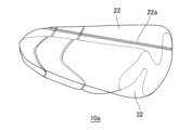
- FIG. 2 is a top perspective view of FIG. 1;
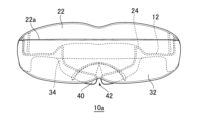
- the lower perspective view of FIG. FIG. 1 is a plan view of a mouthpiece according to a first embodiment of the present invention.
- FIG. 6 is a central vertical cross-sectional view of FIG. 5; Front view of FIG. 5.
- FIG. 6 is a side view of FIG. 5; Rear view of FIG. 5.
- FIG. 6 is a bottom view of FIG. 5;
- FIG. 3 is a plan view of a mouthpiece according to a second embodiment of the present invention.
- Embodiments of the present invention will be described below with reference to FIGS. 1 to 11. However, the present invention is not limited to this embodiment.
- the mouthpiece 10 includes a U-shaped base 12 that corresponds to the curved shape of the tooth row, specifically, the tooth row from the central incisors to at least a portion of the second molars of the upper and lower jaws of the human body. .
- the mouthpiece 10 has a symmetrical shape when viewed from above.
- the base 12 has an upper outer wall 22 that extends toward the maxilla, is positioned between the central incisors of the maxilla and the upper lip when worn, and is configured such that at least the labial side of the central incisors of the maxilla can come into contact with it;
- the upper inner wall 24 is configured to be located between the central incisors of the upper jaw, the second molars, and the hard palate when worn, and is formed from the central incisors of the base 12 to a position corresponding to the first molars. It is growing.
- the upper outer wall 22 and the upper inner wall 24 can be formed in any range up to a position corresponding to the end of the base 12 (see also FIG. 3).
- the base 12 is configured to extend toward the mandible and be located between the central incisors of the mandible and the tongue when worn, so that at least the lingual side of the central incisors of the mandible can come into contact.
- the lower inner wall 34 is configured to be located between the central incisor of the lower jaw, the second molar, and the lower lip when worn, and is formed from the central incisor of the base 12 to a position corresponding to the end. It has a lower outer wall 32.
- the lower inner wall 34 can be formed to a position corresponding to the end of the base 12 or the first molar, and the lower outer wall 32 can be formed to any range up to a position corresponding to the end of the base 12 (see FIG. (See also 4).
- the base 12, the upper outer wall 22, the upper inner wall 24, the lower outer wall 32, and the lower inner wall 34 are made of a known resin material.
- the size, thickness, and shape of the base 12, upper outer wall 22, upper inner wall 24, lower outer wall 32, and lower inner wall 34 can be set arbitrarily. It can be set based on the standard size of .
- the mouthpiece 10 extends from the base 12 toward the upper jaw, and when worn, is positioned between the central incisors of the upper jaw and the upper lip, so that at least the labial side of the central incisors of the upper jaw can come into contact with the mouthpiece 10.
- the upper outer wall 22 is configured to extend from the base 12 toward the lower jaw side, and is configured to be located between the central incisors of the lower jaw and the tongue when worn, so that at least the lingual side of the central incisors of the lower jaw can come into contact.
- the lower inner wall 34 is provided with a lower inner wall 34, when the user lies on his back wearing the mouthpiece 10 and a downward force due to gravity is applied to the user's jaw, at least the central incisors of the lower jaw are exposed to the mouthpiece. 10 to at least the central incisors of the upper jaw, and can prevent the jaw from moving in the downward direction when lying on the back.
- each of the user's teeth can be prevented from becoming uneven, and the position of the mouthpiece in the mouth can also be prevented from shifting.
- the lower inner wall 34 even when the user sleeps on his/her side, when a downward force due to gravity is applied to the user's jaw, any of the teeth in the lower jaw can be moved through the mouthpiece 10 to the upper jaw. It can catch on any of the teeth and prevent the jaw from moving in the downward direction.
- the maxillary surface of the base 12 is provided with first cutting guides 26a, 26b and second cutting guides 28a, 28b.
- the first cutting guides 26a, 26b are attached to at least a portion of the base 12 at a position corresponding to between the second premolar and the first molar, and the second cutting guides 28a, 28b are attached to the first molar. It suffices if it is provided at least in part at a position corresponding to between the first molar and the second molar.
- the base 12 is also provided with first cutting guide parts 36a, 36b and second cutting guide parts 38a, 38b on its mandibular surface.
- the configuration of the first cutting guide parts 36a, 36b and the second cutting guide parts 38a, 38b provided on the mandibular surface is the same as the first cutting guide parts 26a, 26b and the second cutting guide part 28a provided on the maxillary surface. , 28b.
- the first cutting guide part and the second cutting guide part may be provided on either the maxillary surface or the mandibular surface of the base 12.
- the first cutting guides 26a, 26b, 36a, 36b and the second cutting guides 28a, 28b, 38a, 38b are grooves.
- the first cutting guide portions 26a, 26b, 36a, 36b and the second cutting guide portions 28a, 28b, 38a, 38b include grooves, protrusions, protrusions, holes, and holes (continuously provided ones). ), or may be a printed line or broken line. Further, the first cutting guide portions 26a, 26b, 36a, 36b and the second cutting guide portions 28a, 28b, 38a, 38b may be linear or curved.
- the mouthpiece 10 since the mouthpiece 10 is provided with the first cutting guide parts 26a, 26b, 36a, and 36b, the mouthpiece 10 can be moved along the first cutting guide parts 26a, 26b, 36a, and 36b. It is easy to cut at the corresponding position between the second premolar and first molar. A suitable time to use the mouthpiece 10 by cutting it along the first cutting guide portions 26a, 26b, 36a, and 36b is from around the age of five, when the user's first molars begin to grow.
- the mouthpiece 10 can be moved along the second cutting guide parts 28a, 28b, 38a, 38b. It is easy to cut at the corresponding position between the molar and second molar. Thereby, the mouthpiece 10 can be made easy to use even before the second molars have erupted.
- a suitable time to use the mouthpiece 10 by cutting it along the second cutting guides 28a, 28b, 38a, and 38b is when the user is about 7 to 10 years old.
- the first cutting guide portions 26a, 26b , 36a, 36b may be provided on the inner or outer surface of the upper outer wall 22, the upper inner wall 24, the lower outer wall 32, or the lower inner wall 34.
- the second cutting guide parts 28a, 28b, 38a, 38b are It may be provided on the inner or outer surface of the outer wall 22, the upper inner wall 24, the lower outer wall 32, or the lower inner wall 34.
- First cutting guides 26a, 26b, 36a, 36b and second cutting guides 28a, 28b, 38a, 38b are provided on the inner or outer surface of the upper outer wall 22, the upper inner wall 24, the lower outer wall 32, or the lower inner wall 34.
- the first cutting guide portions 26a, 26b, 36a, 36b or the second cutting guide portions 28a, 28b, 38a, 38b are each formed to be inclined toward the central incisors as they move away from the base 12. Good too.
- the upper outer wall 22, the upper inner wall 24, the lower outer wall 32 and the lower inner wall 34 are less likely to interfere with the inside of the cheek, the hard palate, and the tongue, making it possible to provide the mouthpiece 10 that is less likely to cause discomfort when worn.
- FIG. 5 shows a mouthpiece 10a according to the first embodiment of the present invention. Portions having the same configuration as the mouthpiece 10 are given the same reference numerals as the mouthpiece 10.
- the mouthpiece 10a includes a tongue rest 40. As shown in FIGS. 6, 7, and 9, the tongue rest 40 extends from the lower inner wall 34 of the base 12 to a position corresponding to the end of the base 12 or the first molar. It is provided so as to extend inward and toward the lower jaw.
- the tongue rest part 40 is formed to have a groove 42 (see also FIGS. 5 and 10) in the center, and is U-shaped in the same direction as the base part 12.
- the tongue rest part 40 includes first tongue rest cutting guide parts 46a, 46b corresponding to the first cutting guide parts 26a, 26b, 36a, 36b, and a second cutting guide part 46a, 46b.
- Second tongue rest cutting guide portions 48a, 48b are formed corresponding to the guide portions 28a, 28b, 38a, 38b.
- the first tongue rest cutting guide parts 46a, 46b and the second tongue rest cutting guide parts 48a, 48b are the first cutting guide parts 26a, 26b, 36a, 36b and the second cutting guide parts 28a, 28b, 38a, 38b. (See FIGS. 6 and 8.)
- the first tongue rest cutting guide parts 46a, 46b and the second tongue rest cutting guide parts 48a, 48b can also be provided on the bottom side, as shown in FIG.
- the mouthpiece 10a includes the tongue rest 40, when the user's tongue rests on the tongue rest 40, the tip of the tongue easily hits the hard palate, thereby preventing and improving a low tongue and snoring. can be connected to.
- the tongue rest part 40 is provided with the groove 42, the genioglossus muscle is unlikely to interfere with it.
- the tongue rest part 40 includes the first tongue rest cutting guide parts 46a, 46b and the second tongue rest cutting guide parts 48a, 48b, the mouthpiece 10a can be connected to the first and second cutting guide parts 26a, 48b.
- the mouthpiece 10a can be used continuously for a lifetime.
- the tongue rest part 40 can be configured such that its thickness gradually increases from the end of the base part 12 or the position corresponding to the first molar toward the central incisor (Figs. 6 and 7). , 9). With this configuration, the mouthpiece 10a can be made such that the tip of the tongue contacts the hard palate more easily.
- the groove 42 may be expanded toward the end of the base 12, or the first tongue rest cutting guide 46a, 46b and/or the second tongue rest cutting guide may be
- the guide parts 48a, 48b are configured to be inclined toward the central incisors, making it easier to cut along the first tongue rest cutting guide parts 46a, 46b and/or the second tongue rest cutting guide parts 48a, 48b. For example, it is possible to create a mouthpiece with which the genioglossus muscle is less likely to interfere.
- the mouthpiece 10a has an upper outer wall upper cutting guide portion 22a formed on the upper outer wall 22 along the U-shape of the base 12.
- the upper outer wall upper cutting guide part 22a can be formed such that the range above the upper outer wall upper cutting guide part 22a becomes larger toward the central incisor. If the configuration includes the upper outer wall upper cutting guide part 22a, it is easy to cut the upper part of the upper outer wall 22 along the upper outer wall upper cutting guide part 22a, so it is easy to cut the upper part of the upper outer wall 22, so it is easy to cut the upper part of the upper outer wall 22.
- the mouthpiece 10a can be easily worn even when the user is wearing the mouthpiece.
- FIG. 11 shows a mouthpiece 10b according to a second embodiment of the present invention.
- the basic configuration of mouthpiece 10b is the same as mouthpiece 10a, so the differences will be explained below.
- the mass piece 10b includes a U-shaped cutting guide 44 on the tongue rest 40 along the base 12 (see FIGS. 5 and 10). Although illustration and explanation are omitted, the U-shaped cutting guide portion 44 can also be provided on the bottom side. If the configuration includes the U-shaped cutting guide part 44, the tongue rest part 40 can be easily cut along the U-shaped cutting guide part 44, so that the mouthpiece 10b can be made that is unlikely to interfere with bone prominences or the like. .
- the first tongue rest cutting guide parts 46a and 46b, the second tongue rest cutting guide parts 48a and 48b, and the U-shaped cutting guide part 44 are concave grooves. . These may be grooves, protrusions, protrusions, holes (including those provided continuously), or printed lines or broken lines. Moreover, the first tongue rest cutting guide parts 46a, 46b and the second tongue rest cutting guide parts 48a, 48b may be linear or curved.
- the mouthpieces 10a, 10b of the present invention can obtain the following benefits. First, since the mouthpieces 10a and 10b of the same type can be manufactured at a relatively low cost and can be used continuously for a lifetime, there is no need to custom-make a mouthpiece according to the user's dentition, which is economical. be. Next, by preventing the jaw from moving in the downward direction when lying on the back, it is possible to prevent the position of the mandibular condyle from shifting relative to the skull, particularly the mandibular fossa.
- Underdevelopment of the maxillary sinus is considered to be a cause of incisal occlusion and reverse occlusion (socket), so by continuing to use the mouthpieces 10a and 10b from childhood, the development of incisal occlusion and reverse occlusion can be suppressed.
- tooth wear is thought to be a contributing factor to the aging of the mouth, such as narrowing of the mouth and wrinkles around the mouth, including nasolabial folds. Therefore, by interposing a mouthpiece between the teeth of the upper jaw and the lower jaw, it is possible to prevent tooth wear due to friction between the teeth, and thus it is also possible to suppress aging of the mouth area.
Abstract
[Problem] To provide a mouthpiece that can be used continuously throughout life without the need for taking a dental mold when created. [Solution] A mouthpiece 10a comprises a base part 12, an upper outer wall 22, a lower inner wall 34, and a tongue rest part 40. The mouthpiece 10a further comprises first cutting guide parts 26a, 26b, 36a, 36b each formed in at least a portion of a location corresponding to an area between a second bicuspid and a first molar, second cutting guide parts 28a, 28b, 38a, 38b each formed in at least a portion of a location corresponding to an area between the first molar and a second molar, and first tongue rest part cutting guide parts 46a, 46b and/or second tongue rest part cutting guide parts 48a, 48b that are formed in the tongue rest part 40 so as to correspond to respective ones of the above. Thus, the mouthpiece 10a can be easily cut along these cutting guide parts, and a user can continuously use the same type of mouthpiece throughout his/her life from when baby teeth from the central incisors to the second premolars are in place, to when permanent teeth from the central incisors to the second molars are in place.
Description
本発明は、主に、就寝時及び就寝中に装着するマウスピースに関する。
The present invention mainly relates to a mouthpiece that is worn during and while sleeping.
従来、スポーツ時に歯や歯茎、顎関節を保護するためのマウスピースや、不正咬合を治療する歯科器具としてのマウスピースが開発されており、その例として、以下に挙げるものがある。
Conventionally, mouthpieces have been developed to protect teeth, gums, and temporomandibular joints during sports, and as dental instruments to treat malocclusion, examples of which are listed below.
特許文献1には、歯列の前側を覆う前壁部と、歯列の後側を覆う後壁部と、これら前壁部及び後壁部間を接続し、上下顎歯列間の噛み合わせを行わせる噛合部とからなるマウスピースであって、前壁部、後壁部及び噛合部を可撓性且つ衝撃吸収性の多孔質材料で形成し、噛合部は、上下顎歯列間の噛み合わせ力に応じて変形し、前壁部及び後壁部に比較して噛み込み方向断面内の密度が高まり上下顎歯列に密着した噛合安定部を形成可能としたマウスピースが開示されている。
Patent Document 1 describes a front wall portion that covers the front side of the tooth row, a rear wall portion that covers the rear side of the tooth row, and a connection between the front wall portion and the rear wall portion to form a mesh between the upper and lower jaw rows of teeth. This mouthpiece consists of an interlocking part that performs the following: the front wall part, the rear wall part, and the interlocking part are made of a flexible and shock-absorbing porous material, and the interlocking part is between the upper and lower jaw rows of teeth. A mouthpiece is disclosed that deforms in response to occlusal force and has a higher density in the cross-section in the biting direction than the front and rear walls, making it possible to form a stable occlusal area that is in close contact with the upper and lower jaw rows of teeth. There is.
特許文献1のマウスピースによれば、多孔質材料の応力により、噛合部が歯列の形状に合わせて変形して隙間なく密着し、噛合部に前壁部及び後壁部に対し噛み込み方向断面内の密度が相対的に高まった噛合安定部を形成することができるとされている。
According to the mouthpiece disclosed in Patent Document 1, the stress of the porous material deforms the meshing part to match the shape of the tooth row and makes a close contact with the teeth without any gaps. It is said that it is possible to form a meshing stable portion with relatively high density in the cross section.
特許文献2には、上歯と下歯をそれぞれ収容する上顎シェルと下顎シェルとを有し、上顎シェルと下顎シェルは、接触を維持している間分離することができるような方法で連結され、上顎シェルと下顎シェルは、公知の歯科器具よりも大きいそれらの間の厚さを有し、上顎シェルと下顎シェルを連結する手段も、公知の歯科器具よりも大きい厚さであるマウスピースが開示されている。
Patent Document 2 has an upper jaw shell and a lower jaw shell that house upper teeth and lower teeth, respectively, and the upper jaw shell and the lower jaw shell are connected in such a way that they can be separated while maintaining contact. , the upper and lower shells have a thickness between them that is greater than known dental appliances, and the means for connecting the upper and lower shells also has a mouthpiece that is of greater thickness than known dental appliances. Disclosed.
特許文献2のマウスピースによれば、ユーザの口腔の奥で大臼歯を治療することができ、上顎シェルと下顎シェルとの間の厚みにより、ユーザが口腔内に歯科器具を設置するとき、ユーザの口腔内の筋肉を刺激することができ、歯科器具の上顎シェルと下顎シェルとを連結するヒンジや他の手段は、
後方部分の増加した厚さのために歯科器具全体を弾力的にするのを可能にし、上顎シェルと下顎シェルとを連結する手段は、ユーザの顎の反対側面の移動を制限することができるとされている。 According to the mouthpiece of Patent Document 2, molar teeth can be treated at the back of the user's oral cavity, and due to the thickness between the upper jaw shell and the lower jaw shell, when the user installs a dental instrument in the oral cavity, the user The hinge or other means connecting the upper and lower jaw shells of the dental appliance can stimulate the muscles in the oral cavity.
The increased thickness of the posterior portion allows the entire dental appliance to be elastic, and the means for connecting the upper and lower jaw shells can limit movement of the opposite side of the user's jaw. has been done.
特許文献3には、上顎及び下顎の中切歯から第二大臼歯の少なくとも一部までに対応するU字形の基部と、基部から上顎側に延設され、装着時に、上顎の中切歯と上唇の間に位置し、上顎の少なくとも中切歯の唇側面が当接し得るように構成された上外壁と、基部から下顎側に延設され、装着時に、下顎の中切歯と舌の間に位置し、下顎の少なくとも中切歯の舌側面が当接し得るように構成された下内壁を具え、基部の、臼歯部位に対応する位置の少なくとも一部に、第一切断案内部が形成されているマウスピースが開示されている。また、特許文献4には、第一大臼歯と第二大臼歯の間に対応する位置に切断案内部が形成されたマウスピースが開示されている。
Patent Document 3 discloses a U-shaped base that corresponds to the central incisors of the upper and lower jaws to at least part of the second molars, and a U-shaped base that extends from the base to the upper jaw side and that, when worn, connects the central incisors of the upper jaw to at least a portion of the second molars. The upper outer wall is located between the upper lip and is configured so that the labial side of at least the central incisor of the upper jaw can come into contact with it, and the upper outer wall is located between the central incisor of the lower jaw and the tongue and extends from the base to the mandibular side and when worn. a lower inner wall configured such that at least the lingual side of the central incisor of the lower jaw can come into contact with the lower inner wall, and a first cutting guide portion is formed in at least a portion of the base at a position corresponding to the molar region. A mouthpiece is disclosed. Further, Patent Document 4 discloses a mouthpiece in which a cutting guide portion is formed at a position corresponding to between a first molar and a second molar.
ところで、昨今の医療技術の進歩により、人間の寿命は延びてきており、何らの対策をしない場合、生涯にわたり自らの歯を維持することは難しい。そこで、マウスピースを用いることによって、歯を保護することが重要となるが、マウスピースは、個人の歯型を取って作成(オーダーメイド)されるか、標準的な歯列を基準に作成されたのが市販されているのが通常である。前者は高価になり易く、後者は、歯列に合うマウスピースを探し難いという問題がある。
By the way, due to recent advances in medical technology, human lifespans are increasing, and if no measures are taken, it will be difficult to maintain one's own teeth throughout one's life. Therefore, it is important to protect the teeth by using a mouthpiece, but mouthpieces are either made by taking molds of the individual's teeth (custom-made) or are made based on a standard dentition. These are usually commercially available. The former tends to be expensive, and the latter has the problem that it is difficult to find a mouthpiece that fits the alignment of the teeth.
そこで、本発明は、歯型を取って作成しなくても、生涯継続して使用することができるマウスピースを提供することをその目的とする。
Therefore, an object of the present invention is to provide a mouthpiece that can be used continuously for a lifetime without the need to take impressions of the teeth.
本発明は、上顎及び下顎の中切歯から第二大臼歯の少なくとも一部までに対応するU字形の基部と、
前記基部から前記上顎側に延設され、装着時に、前記上顎の中切歯と上唇の間に位置し、前記上顎の少なくとも中切歯の唇側面が当接し得るように構成された上外壁と、
前記基部から前記下顎側に延設され、装着時に、前記下顎の中切歯と舌の間に位置し、前記下顎の少なくとも中切歯の舌側面が当接し得るように構成され、前記基部の端部又は第一大臼歯に対応する位置まで形成された下内壁と、
前記下内壁から前記基部のU字の内側、且つ、下顎方向に延出し、中央に溝を有することにより前記基部と同方向のU字形をなす舌置部を具え、
前記基部及び下内壁の、第二小臼歯と第一大臼歯の間に対応する位置の少なくとも一部に、第一切断案内部が形成され、
前記基部及び下内壁の、第一大臼歯と第二大臼歯の間に対応する位置の少なくとも一部に、第二切断案内部が形成され、
前記第一切断案内部及び第二切断案内部とそれぞれ対応する第一舌置部切断案内部及び第二舌置部切断案内部が前記舌置部に形成されていることを特徴とするマウスピースによって前記課題を解決した。 The present invention includes a U-shaped base corresponding to at least a portion of the upper and lower central incisors to the second molars;
an upper outer wall extending from the base to the maxillary side, positioned between the central incisors of the maxilla and the upper lip when worn, and configured such that the labial side of at least the central incisors of the maxilla can come into contact; ,
Extending from the base to the mandibular side, positioned between the central incisors of the mandible and the tongue when worn, and configured such that the lingual side of at least the central incisors of the mandible can come into contact with the base. a lower inner wall formed to a position corresponding to the end or first molar;
a tongue rest extending from the lower inner wall to the inside of the U-shape of the base and in the direction of the lower jaw, and having a groove in the center to form a U-shape in the same direction as the base;
A first cutting guide portion is formed in at least a portion of the base and the lower inner wall at a position corresponding to between the second premolar and the first molar,
A second cutting guide portion is formed in at least a portion of the base and the lower inner wall at a position corresponding to between the first molar and the second molar,
A mouthpiece characterized in that a first tongue rest cutting guide and a second tongue rest cutting guide that correspond to the first cutting guide and the second cutting guide, respectively, are formed in the tongue rest. The above problem was solved.
本発明のマウスピースによれば、基部から上顎側に延設され、装着時に、上顎の中切歯と上唇の間に位置し、上顎の少なくとも中切歯の唇側面が当接し得るように構成された上外壁と、基部から下顎側に延設され、装着時に、下顎の中切歯と舌の間に位置し、下顎の少なくとも中切歯の舌側面が当接し得るように構成された下内壁を具えているから、マウスピースを装着した状態で仰向けとなり、顎に重力による垂下方向の力がかかったとき、下顎の少なくとも中切歯がマウスピースを介して上顎の少なくとも中切歯に引っ掛かり、仰向け時の顎の垂下方向の移動を防止することができる。また、下内壁から基部の内側、且つ、下顎方向に延出し、中央に溝を有することによりU字形をなす舌置部を具えるので、舌置部に舌が載ることにより、舌尖が硬口蓋に当たり易くなり、低位舌や鼾の予防及び改善に繋がる。また、上顎及び下顎の中切歯から第二大臼歯の少なくとも一部までに対応するU字形の基部及び下内壁が、第二小臼歯と第一大臼歯の間と第一大臼歯と第二大臼歯の間のそれぞれに対応する位置の少なくとも一部に第一切断案内部及び第二切断案内部を具え、舌置部が第一切断案内部及び第二切断案内部とそれぞれ対応する第一舌置部切断案内部及び第二舌置部切断案内部を具えているので、マウスピースを第一・第二切断案内部と第一・第二舌置部切断案内部に沿って、第二小臼歯と第一大臼歯の間と第一大臼歯と第二大臼歯の間のそれぞれに対応する位置で切断し易い。これにより、中切歯から第二小臼歯までの乳歯が生え揃っているときから、第二大臼歯が生える前の状態と、中切歯から第二大臼歯の永久歯が生え揃うときまで、同型のマウスピースを生涯継続して使用することができる。
According to the mouthpiece of the present invention, the mouthpiece extends from the base to the maxillary side, is positioned between the central incisors of the maxilla and the upper lip when worn, and is configured such that at least the labial side of the central incisors of the maxilla can come into contact. The upper outer wall extends from the base to the mandibular side and is located between the central incisors of the mandible and the tongue when worn, and is configured such that at least the lingual side of the central incisors of the mandible can come into contact. Because it has an inner wall, when you lie on your back with the mouthpiece on and a downward force due to gravity is applied to your jaw, at least the central incisors of the lower jaw will catch on at least the central incisors of the upper jaw through the mouthpiece. , it is possible to prevent the jaw from moving in the downward direction when lying on the back. In addition, it has a U-shaped tongue rest that extends from the lower inner wall to the inside of the base and in the direction of the mandible and has a groove in the center, so when the tongue rests on the tongue rest, the tip of the tongue touches the hard palate. This will help prevent and improve low tongue and snoring. In addition, the U-shaped base and lower inner wall corresponding to at least a portion of the upper and lower central incisors to the second molars are formed between the second premolars and the first molars and between the first molars and the second molars. A first cutting guide and a second cutting guide are provided at least in part at corresponding positions between the molar teeth, and the tongue resting part is provided with a first cutting guide and a second cutting guide corresponding to the first cutting guide and the second cutting guide, respectively. Since the tongue rest cutting guide part and the second tongue rest cutting guide part are provided, the mouthpiece can be moved along the first and second cutting guide parts and the first and second tongue rest cutting guide parts. It is easy to cut at positions corresponding to between premolars and first molars and between first molars and second molars. This ensures that the condition is the same from when all the baby teeth from the central incisors to the second premolars have erupted, to before the second molars have erupted, to when the permanent teeth from the central incisors to the second molars have erupted. The mouthpiece can be used continuously for a lifetime.
これにより、本発明のマウスピースの使用者は、以下のような利益を得られる。まず、比較的低コストで製造可能な同型のマウスピースを生涯継続して使用することができるので、使用者の歯列に応じたマウスピースをオーダーメイドせずに済み、経済的である。次に、仰向け時の顎の垂下方向の移動を防止することができることにより、頭蓋骨、特に下顎窩に対する下顎頭の位置がずれることを防止することができる。これにより、顎関節症の発症や、下顎頭が耳孔方向に移動して耳孔や下顎枝部、これらの周辺の神経を押し潰すことによって発症する難聴その他の症状の発症を防止することができる。また、マウスピースを装着して就寝することにより、鼻呼吸優位となり、口内の乾燥を防ぎ、菌やウィルスの増殖を防ぐことができるとともに、いびき防止にも繋がる。特に、中切歯から第二小臼歯までの乳歯が生え揃っている幼児の段階においては、就寝時の鼻呼吸優位の状態が、上顎洞の成長を促進させ得る。ところで、上顎洞の未発達は、切端咬合や反対咬合(受け口)の一因と考えられるので、本発明のマウスピースを幼児の頃から使用し続けることにより、切端咬合や反対咬合の発症を抑制できる。また、歯の摩耗は、口が窄むことやほうれい線を含む口周りのしわ等の口元の老化の一因と考えられる。そこで、上顎と下顎の歯の間にマウスピースが介在することにより、歯同士の摩擦による歯の摩耗を防ぐことができるので、口元の老化を抑制することもできる。
As a result, the user of the mouthpiece of the present invention can obtain the following benefits. First, since the same type of mouthpiece can be manufactured at a relatively low cost and can be used continuously for a lifetime, there is no need to custom-make a mouthpiece according to the user's dentition, which is economical. Next, by preventing the jaw from moving in the downward direction when lying on the back, it is possible to prevent the position of the mandibular condyle from shifting relative to the skull, particularly the mandibular fossa. This can prevent the onset of temporomandibular joint disorder and the onset of hearing loss and other symptoms caused by the mandibular condyle moving toward the ear canal and crushing the ear canal, mandibular ramus, and the surrounding nerves. In addition, by wearing a mouthpiece while sleeping, you will have an advantage in breathing through your nose, which will prevent your mouth from drying out, prevent the growth of bacteria and viruses, and also help prevent snoring. In particular, at the stage of infants when all the baby teeth from the central incisors to the second premolars have erupted, the state of dominant nasal breathing during sleep can promote the growth of the maxillary sinus. By the way, underdevelopment of the maxillary sinus is thought to be a cause of incisal occlusion and reverse occlusion (receptacle), so by continuing to use the mouthpiece of the present invention from childhood, the development of incisal occlusion and reverse occlusion can be suppressed. can. In addition, tooth wear is thought to be a contributing factor to the aging of the mouth, such as narrowing of the mouth and wrinkles around the mouth, including nasolabial folds. Therefore, by interposing a mouthpiece between the teeth of the upper jaw and the lower jaw, it is possible to prevent tooth wear due to friction between the teeth, and thus it is also possible to suppress aging of the mouth area.
また、舌置部の厚みが基部の端部又は第一大臼歯に対応する位置から中切歯側に向けて次第に厚くなっている構成とすれば、舌尖が硬口蓋にさらに当たり易いマウスピースとすることができる。
In addition, if the thickness of the tongue rest gradually increases from the end of the base or the position corresponding to the first molar toward the central incisors, the tongue tip can more easily contact the hard palate. can do.
また、舌置部の溝が基部の端部方向に拡開している構成、或いは、第一舌置部切断案内部及び/又は第二舌置部切断案内部が中切歯方向に傾斜している構成とし、第一舌置部切断案内部及び/又は第二舌置部切断案内部に沿って切断し易くすれば、オトガイ舌筋が干渉し難いマウスピースとすることができる。
In addition, the groove of the tongue rest may be expanded toward the end of the base, or the first tongue rest cutting guide and/or the second tongue rest cutting guide may be inclined toward the central incisor. If the mouthpiece is configured such that it is easy to cut along the first tongue rest section cutting guide section and/or the second tongue rest section cutting guide section, it is possible to obtain a mouthpiece in which the genioglossus muscle is less likely to interfere.
また、舌置部が基部に沿うU字状切断案内部をさらに具える構成とし、U字状切断案内部に沿って切断し易くすれば、骨隆起等に干渉し難いマウスピースとすることができる。
Furthermore, if the tongue rest further includes a U-shaped cutting guide along the base, and the tongue rest is made easier to cut along the U-shaped cutting guide, the mouthpiece can be made less likely to interfere with bone prominences, etc. can.
また、上外壁、上内壁、及び下外壁が基部の端部又は第一大臼歯に対応する位置まで形成されている構成とすれば、上外壁、上内壁、又は下外壁に使用者の各歯が沿うことになり、乱杭歯を防止することができ、口内でマウスピースの位置がずれることを防止することもでき、使用者が横向きに寝た場合にも、顎の垂下方向の移動を防止することができる。
In addition, if the upper outer wall, upper inner wall, and lower outer wall are formed up to the end of the base or the position corresponding to the first molar, each of the user's teeth may be attached to the upper outer wall, upper inner wall, or lower outer wall. This prevents the teeth from becoming misaligned, prevents the mouthpiece from shifting in the mouth, and prevents the jaw from moving in the drooping direction even when the user sleeps on his or her side. can do.
また、上外壁が、基部のU字に沿う上外壁上部切断案内部をさらに具える構成とすれば、上外壁の上部を上外壁上部切断案内部に沿って切断し易いので、子供や女性など、口内が比較的小さい使用者であっても装着し易いマウスピースとすることができる。
In addition, if the upper outer wall is configured to further include an upper outer wall upper cutting guide part along the U-shape of the base, it is easier to cut the upper part of the upper outer wall along the upper outer wall upper cutting guide part, so that children, women, etc. The mouthpiece can be easily worn even by a user with a relatively small mouth.
以下、本発明の実施形態を図1~11を参照して説明する。但し、本発明はこの実施形態に限定されるものではない。
Embodiments of the present invention will be described below with reference to FIGS. 1 to 11. However, the present invention is not limited to this embodiment.
図1~4は、本発明の参考例のマウスピース10を示している。本発明の舌置部40(後述する。)以外の構成は、マウスピース10と同様であるため、まず、マウスピース10について説明する。マウスピース10は、歯列、具体的には、人体の上顎及び下顎の中切歯から第二大臼歯の少なくとも一部までの歯列の湾曲形状に対応したU字形の基部12を具えている。マウスピース10は、平面視で左右対称の形状を具えている。
1 to 4 show a mouthpiece 10 as a reference example of the present invention. The configuration of the present invention other than the tongue rest 40 (described later) is the same as the mouthpiece 10, so the mouthpiece 10 will be described first. The mouthpiece 10 includes a U-shaped base 12 that corresponds to the curved shape of the tooth row, specifically, the tooth row from the central incisors to at least a portion of the second molars of the upper and lower jaws of the human body. . The mouthpiece 10 has a symmetrical shape when viewed from above.
基部12は、上顎側に延設され、装着時に、上顎の中切歯と上唇の間に位置し、上顎の少なくとも中切歯の唇側面が当接し得るように構成された上外壁22と、装着時に、上顎の中切歯から第二大臼歯と硬口蓋の間に位置するように構成され、基部12の中切歯から第一大臼歯に対応する位置まで形成された上内壁24を具えている。上外壁22及び上内壁24は、基部12の端部に対応する位置までの任意の範囲で形成することができる(図3も参照。)。
The base 12 has an upper outer wall 22 that extends toward the maxilla, is positioned between the central incisors of the maxilla and the upper lip when worn, and is configured such that at least the labial side of the central incisors of the maxilla can come into contact with it; The upper inner wall 24 is configured to be located between the central incisors of the upper jaw, the second molars, and the hard palate when worn, and is formed from the central incisors of the base 12 to a position corresponding to the first molars. It is growing. The upper outer wall 22 and the upper inner wall 24 can be formed in any range up to a position corresponding to the end of the base 12 (see also FIG. 3).
図2に示すように、基部12は、下顎側に延設され、装着時に、下顎の中切歯と舌の間に位置し、下顎の少なくとも中切歯の舌側面が当接し得るように構成された下内壁34と、装着時に、下顎の中切歯から第二大臼歯と下唇の間に位置するように構成され、基部12の中切歯から端部に対応する位置まで形成された下外壁32を具えている。下内壁34は、基部12の端部又は第一大臼歯に対応する位置まで形成され、下外壁32は、基部12の端部に対応する位置までの任意の範囲で形成することができる(図4も参照。)。
As shown in FIG. 2, the base 12 is configured to extend toward the mandible and be located between the central incisors of the mandible and the tongue when worn, so that at least the lingual side of the central incisors of the mandible can come into contact. The lower inner wall 34 is configured to be located between the central incisor of the lower jaw, the second molar, and the lower lip when worn, and is formed from the central incisor of the base 12 to a position corresponding to the end. It has a lower outer wall 32. The lower inner wall 34 can be formed to a position corresponding to the end of the base 12 or the first molar, and the lower outer wall 32 can be formed to any range up to a position corresponding to the end of the base 12 (see FIG. (See also 4).
基部12、上外壁22、上内壁24,下外壁32,及び下内壁34は、公知の樹脂材料で構成されている。基部12、上外壁22、上内壁24,下外壁32,及び下内壁34の大きさ、厚み、及び形状は、任意に設定することができ、例えば、性別ごとの歯列の標準モデルや口腔内の標準的な大きさを基準にして設定すればよい。
The base 12, the upper outer wall 22, the upper inner wall 24, the lower outer wall 32, and the lower inner wall 34 are made of a known resin material. The size, thickness, and shape of the base 12, upper outer wall 22, upper inner wall 24, lower outer wall 32, and lower inner wall 34 can be set arbitrarily. It can be set based on the standard size of .
このように、マウスピース10は、基部12から上顎側に延設され、装着時に、上顎の中切歯と上唇の間に位置し、上顎の少なくとも中切歯の唇側面が当接し得るように構成された上外壁22と、基部12から下顎側に延設され、装着時に、下顎の中切歯と舌の間に位置し、下顎の少なくとも中切歯の舌側面が当接し得るように構成された下内壁34を具えているから、使用者がマウスピース10を装着した状態で仰向けとなり、使用者の顎に重力による垂下方向の力がかかったとき、下顎の少なくとも中切歯がマウスピース10を介して上顎の少なくとも中切歯に引っ掛かり、仰向け時の顎の垂下方向の移動を防止することができる。
In this way, the mouthpiece 10 extends from the base 12 toward the upper jaw, and when worn, is positioned between the central incisors of the upper jaw and the upper lip, so that at least the labial side of the central incisors of the upper jaw can come into contact with the mouthpiece 10. The upper outer wall 22 is configured to extend from the base 12 toward the lower jaw side, and is configured to be located between the central incisors of the lower jaw and the tongue when worn, so that at least the lingual side of the central incisors of the lower jaw can come into contact. Since the lower inner wall 34 is provided with a lower inner wall 34, when the user lies on his back wearing the mouthpiece 10 and a downward force due to gravity is applied to the user's jaw, at least the central incisors of the lower jaw are exposed to the mouthpiece. 10 to at least the central incisors of the upper jaw, and can prevent the jaw from moving in the downward direction when lying on the back.
また、上外壁22、上内壁24,下外壁32、及び下内壁34が基部12の端部又は第一大臼歯に対応する位置まで形成されている構成とすれば、上外壁22、上内壁24、下外壁32、又は下内壁34に使用者の各歯が沿うことになり、乱杭歯を防止することができ、口内におけるマウスピースの位置がずれることを防止することもできる。
Furthermore, if the upper outer wall 22, the upper inner wall 24, the lower outer wall 32, and the lower inner wall 34 are formed up to a position corresponding to the end of the base 12 or the first molar, the upper outer wall 22, the upper inner wall 24 , the lower outer wall 32 or the lower inner wall 34, each of the user's teeth can be prevented from becoming uneven, and the position of the mouthpiece in the mouth can also be prevented from shifting.
また、基部12の端部又は第一大臼歯に対応する位置まで形成された上外壁22又は上内壁24と、基部12の端部又は第一大臼歯に対応する位置まで形成された下外壁32又は下内壁34を設けることにより、使用者が横向きに寝た場合にも、使用者の顎に重力による垂下方向の力がかかったとき、下顎のいずれかの歯がマウスピース10を介して上顎のいずれかの歯に引っ掛かり、顎の垂下方向の移動を防止することができる。
Also, an upper outer wall 22 or an upper inner wall 24 formed up to a position corresponding to the end of the base 12 or the first molar, and a lower outer wall 32 formed up to a position corresponding to the end of the base 12 or the first molar. Alternatively, by providing the lower inner wall 34, even when the user sleeps on his/her side, when a downward force due to gravity is applied to the user's jaw, any of the teeth in the lower jaw can be moved through the mouthpiece 10 to the upper jaw. It can catch on any of the teeth and prevent the jaw from moving in the downward direction.
図1に示すように、基部12の上顎面には、第一切断案内部26a,26bと第二切断案内部28a,28bが設けられている。第一切断案内部26a,26bは、基部12の第二小臼歯と第一大臼歯の間に対応する位置の少なくとも一部に、そして、第二切断案内部28a,28bは、第一大臼歯と第二大臼歯の間に対応する位置の少なくとも一部に設けられていればよい。
As shown in FIG. 1, the maxillary surface of the base 12 is provided with first cutting guides 26a, 26b and second cutting guides 28a, 28b. The first cutting guides 26a, 26b are attached to at least a portion of the base 12 at a position corresponding to between the second premolar and the first molar, and the second cutting guides 28a, 28b are attached to the first molar. It suffices if it is provided at least in part at a position corresponding to between the first molar and the second molar.
図2に示すように、基部12は、その下顎面にも、第一切断案内部36a,36bと第二切断案内部38a,38bが設けられている。下顎面に設けられている第一切断案内部36a,36bと第二切断案内部38a,38bの構成は、上顎面に設けられている第一切断案内部26a,26bと第二切断案内部28a,28bの構成と同様である。なお、第一切断案内部と第二切断案内部は、基部12の上顎面又は下顎面のいずれかに設けた構成とすることもできる。
As shown in FIG. 2, the base 12 is also provided with first cutting guide parts 36a, 36b and second cutting guide parts 38a, 38b on its mandibular surface. The configuration of the first cutting guide parts 36a, 36b and the second cutting guide parts 38a, 38b provided on the mandibular surface is the same as the first cutting guide parts 26a, 26b and the second cutting guide part 28a provided on the maxillary surface. , 28b. Note that the first cutting guide part and the second cutting guide part may be provided on either the maxillary surface or the mandibular surface of the base 12.
マウスピース10の場合、第一切断案内部26a,26b,36a,36b及び第二切断案内部28a,28b,38a,38bは、凹溝である。第一切断案内部26a,26b,36a,36b及び第二切断案内部28a,28b,38a,38bは、凹溝の他、突条、突起又は孔や穴(連続して設けられているものを含む。)、或いは、印刷した線や破線であってもよい。また、第一切断案内部26a,26b,36a,36b及び第二切断案内部28a,28b,38a,38bは、直線状であっても曲線状であってもよい。
In the case of the mouthpiece 10, the first cutting guides 26a, 26b, 36a, 36b and the second cutting guides 28a, 28b, 38a, 38b are grooves. The first cutting guide portions 26a, 26b, 36a, 36b and the second cutting guide portions 28a, 28b, 38a, 38b include grooves, protrusions, protrusions, holes, and holes (continuously provided ones). ), or may be a printed line or broken line. Further, the first cutting guide portions 26a, 26b, 36a, 36b and the second cutting guide portions 28a, 28b, 38a, 38b may be linear or curved.
このように、マウスピース10には、第一切断案内部26a,26b,36a,36bが設けられているから、マウスピース10を第一切断案内部26a,26b,36a,36bに沿って、第二小臼歯と第一大臼歯の間に対応する位置で切断し易い。マウスピース10を第一切断案内部26a,26b,36a,36bに沿って切断して使用するのに好適な時期は、使用者の第一大臼歯が生え始めた5才頃からである。これにより、中切歯から第二小臼歯までの乳歯が生え揃っているときから、中切歯から第二大臼歯の永久歯が生え揃うときまで、同型のマウスピースを生涯継続して使用することができる。
As described above, since the mouthpiece 10 is provided with the first cutting guide parts 26a, 26b, 36a, and 36b, the mouthpiece 10 can be moved along the first cutting guide parts 26a, 26b, 36a, and 36b. It is easy to cut at the corresponding position between the second premolar and first molar. A suitable time to use the mouthpiece 10 by cutting it along the first cutting guide portions 26a, 26b, 36a, and 36b is from around the age of five, when the user's first molars begin to grow. This allows you to continue using the same type of mouthpiece throughout your life, from when all the baby teeth from the central incisors to the second premolars have erupted, until all the permanent teeth from the central incisors to the second molars have erupted. I can do it.
また、マウスピース10に第二切断案内部28a,28b,38a,38bが設けられている構成とすれば、マウスピース10を第二切断案内部28a,28b,38a,38bに沿って、第一大臼歯と第二大臼歯の間に対応する位置で切断し易い。これにより、第二大臼歯が生える前の状態であっても使用し易いマウスピース10とすることができる。マウスピース10を第二切断案内部28a,28b,38a,38bに沿って切断して使用するのに好適な時期は、使用者が7才~10才くらいのときである。
Furthermore, if the mouthpiece 10 is provided with the second cutting guide parts 28a, 28b, 38a, 38b, the mouthpiece 10 can be moved along the second cutting guide parts 28a, 28b, 38a, 38b. It is easy to cut at the corresponding position between the molar and second molar. Thereby, the mouthpiece 10 can be made easy to use even before the second molars have erupted. A suitable time to use the mouthpiece 10 by cutting it along the second cutting guides 28a, 28b, 38a, and 38b is when the user is about 7 to 10 years old.
ここで、上外壁22、上内壁24,下外壁32,又は下内壁34が基部12の中切歯から第一大臼歯に対応する位置まで形成されている場合、第一切断案内部26a,26b,36a,36bは、上外壁22、上内壁24,下外壁32,又は下内壁34の内側面又は外側面に設けられていてもよい。
Here, if the upper outer wall 22, the upper inner wall 24, the lower outer wall 32, or the lower inner wall 34 is formed from the central incisor of the base 12 to the position corresponding to the first molar, the first cutting guide portions 26a, 26b , 36a, 36b may be provided on the inner or outer surface of the upper outer wall 22, the upper inner wall 24, the lower outer wall 32, or the lower inner wall 34.
さらに、上外壁22、上内壁24,下外壁32,又は下内壁34が基部12の端部に対応する位置まで形成されている場合、第二切断案内部28a,28b,38a,38bは、上外壁22、上内壁24,下外壁32,又は下内壁34の内側面又は外側面に設けられていてもよい。
Furthermore, when the upper outer wall 22, the upper inner wall 24, the lower outer wall 32, or the lower inner wall 34 is formed to a position corresponding to the end of the base 12, the second cutting guide parts 28a, 28b, 38a, 38b are It may be provided on the inner or outer surface of the outer wall 22, the upper inner wall 24, the lower outer wall 32, or the lower inner wall 34.
上外壁22、上内壁24,下外壁32,又は下内壁34の内側面又は外側面に第一切断案内部26a,26b,36a,36b及び第二切断案内部28a,28b,38a,38bを設けた場合、第一切断案内部26a,26b,36a,36b又は第二切断案内部28a,28b,38a,38bは、それぞれ、基部12から離れるに従って、中切歯方向に傾斜するように形成してもよい。本構成により、第一切断案内部26a,26b,36a,36b又は第二切断案内部28a,28b,38a,38bに沿ってマウスピース10を切断したとき、上外壁22、上内壁24,下外壁32,及び下内壁34が頬の内側や硬口蓋、舌に干渉し難くなるので、装着時の違和感を生じ難いマウスピース10とすることができる。
First cutting guides 26a, 26b, 36a, 36b and second cutting guides 28a, 28b, 38a, 38b are provided on the inner or outer surface of the upper outer wall 22, the upper inner wall 24, the lower outer wall 32, or the lower inner wall 34. In this case, the first cutting guide portions 26a, 26b, 36a, 36b or the second cutting guide portions 28a, 28b, 38a, 38b are each formed to be inclined toward the central incisors as they move away from the base 12. Good too. With this configuration, when the mouthpiece 10 is cut along the first cutting guides 26a, 26b, 36a, 36b or the second cutting guides 28a, 28b, 38a, 38b, the upper outer wall 22, the upper inner wall 24, the lower outer wall 32 and the lower inner wall 34 are less likely to interfere with the inside of the cheek, the hard palate, and the tongue, making it possible to provide the mouthpiece 10 that is less likely to cause discomfort when worn.
図5は、本発明の第一実施形態のマウスピース10aを示している。マウスピース10と同様の構成を具える部分は、マウスピース10と同じ符号を付している。マウスピース10aは、舌置部40を具える。舌置部40は、図6,7,9にも示されているように、基部12の端部又は第一大臼歯に対応する位置まで形成されている下内壁34から基部12のU字の内側、且つ、下顎方向に延出するように設けられている。ここで、舌置部40は、中央に溝42(図5,10も参照。)を有するように形成されており、基部12と同方向のU字形をなしている。
FIG. 5 shows a mouthpiece 10a according to the first embodiment of the present invention. Portions having the same configuration as the mouthpiece 10 are given the same reference numerals as the mouthpiece 10. The mouthpiece 10a includes a tongue rest 40. As shown in FIGS. 6, 7, and 9, the tongue rest 40 extends from the lower inner wall 34 of the base 12 to a position corresponding to the end of the base 12 or the first molar. It is provided so as to extend inward and toward the lower jaw. Here, the tongue rest part 40 is formed to have a groove 42 (see also FIGS. 5 and 10) in the center, and is U-shaped in the same direction as the base part 12.
また、図5に示されているように、舌置部40には、第一切断案内部26a,26b,36a,36bに対応する第一舌置部切断案内部46a,46bと、第二切断案内部28a,28b,38a,38bに対応する第二舌置部切断案内部48a,48bが形成されている。第一舌置部切断案内部46a,46bと第二舌置部切断案内部48a,48bは、第一切断案内部26a,26b,36a,36b及び第二切断案内部28a,28b,38a,38bとそれぞれ連続するように設けることができる(図6,8参照。)。また、第一舌置部切断案内部46a,46bと第二舌置部切断案内部48a,48bは、図10に示すように、底面側に設けることもできる。
Further, as shown in FIG. 5, the tongue rest part 40 includes first tongue rest cutting guide parts 46a, 46b corresponding to the first cutting guide parts 26a, 26b, 36a, 36b, and a second cutting guide part 46a, 46b. Second tongue rest cutting guide portions 48a, 48b are formed corresponding to the guide portions 28a, 28b, 38a, 38b. The first tongue rest cutting guide parts 46a, 46b and the second tongue rest cutting guide parts 48a, 48b are the first cutting guide parts 26a, 26b, 36a, 36b and the second cutting guide parts 28a, 28b, 38a, 38b. (See FIGS. 6 and 8.) Further, the first tongue rest cutting guide parts 46a, 46b and the second tongue rest cutting guide parts 48a, 48b can also be provided on the bottom side, as shown in FIG.
上述したように、マウスピース10aは、舌置部40を具えるので、舌置部40に使用者の舌が載ることにより、その舌尖が硬口蓋に当たり易くなり、低位舌や鼾の予防及び改善に繋げることができる。このとき、舌置部40は溝42を具えるので、オトガイ舌筋が干渉し難い。また、舌置部40は第一舌置部切断案内部46a,46bと第二舌置部切断案内部48a,48bを具えているので、マウスピース10aを第一・第二切断案内部26a,26b,36a,36b,28a,28b,38a,38bと第一・第二舌置部切断案内部46a,46b,48a,48bに沿って、第二小臼歯と第一大臼歯の間と第一大臼歯と第二大臼歯の間のそれぞれに対応する位置で切断し易い。これにより、中切歯から第二小臼歯までの乳歯が生え揃っているときから、第二大臼歯が生える前の状態と、中切歯から第二大臼歯の永久歯が生え揃うときまで、同型のマウスピース10aを生涯継続して使用することができる。
As described above, since the mouthpiece 10a includes the tongue rest 40, when the user's tongue rests on the tongue rest 40, the tip of the tongue easily hits the hard palate, thereby preventing and improving a low tongue and snoring. can be connected to. At this time, since the tongue rest part 40 is provided with the groove 42, the genioglossus muscle is unlikely to interfere with it. Moreover, since the tongue rest part 40 includes the first tongue rest cutting guide parts 46a, 46b and the second tongue rest cutting guide parts 48a, 48b, the mouthpiece 10a can be connected to the first and second cutting guide parts 26a, 48b. 26b, 36a, 36b, 28a, 28b, 38a, 38b and the first and second tongue rest cutting guide parts 46a, 46b, 48a, 48b, between the second premolar and the first molar and the first Easy to cut at positions corresponding to the areas between the molars and second molars. This ensures that the condition is the same from when all the baby teeth from the central incisors to the second premolars have erupted, to before the second molars have erupted, to when the permanent teeth from the central incisors to the second molars have erupted. The mouthpiece 10a can be used continuously for a lifetime.
ここで、舌置部40は、その厚みが基部12の端部又は第一大臼歯に対応する位置から中切歯側に向けて次第に厚くなっている構成とすることができる(図6,7,9参照。)。本構成とすることにより、舌尖が硬口蓋にさらに当たり易いマウスピース10aとすることができる。
Here, the tongue rest part 40 can be configured such that its thickness gradually increases from the end of the base part 12 or the position corresponding to the first molar toward the central incisor (Figs. 6 and 7). , 9). With this configuration, the mouthpiece 10a can be made such that the tip of the tongue contacts the hard palate more easily.
また、図5,10に示すように、溝42が基部12の端部方向に拡開している構成、或いは、第一舌置部切断案内部46a,46b及び/又は第二舌置部切断案内部48a,48bが中切歯方向に傾斜している構成とし、第一舌置部切断案内部46a,46b及び/又は第二舌置部切断案内部48a,48bに沿って切断し易くすれば、オトガイ舌筋がさらに干渉し難いマウスピースとすることができる。
In addition, as shown in FIGS. 5 and 10, the groove 42 may be expanded toward the end of the base 12, or the first tongue rest cutting guide 46a, 46b and/or the second tongue rest cutting guide may be The guide parts 48a, 48b are configured to be inclined toward the central incisors, making it easier to cut along the first tongue rest cutting guide parts 46a, 46b and/or the second tongue rest cutting guide parts 48a, 48b. For example, it is possible to create a mouthpiece with which the genioglossus muscle is less likely to interfere.
マウスピース10aは、図7,8に示すように、上外壁22に基部12のU字に沿う上外壁上部切断案内部22aが形成されている。上外壁上部切断案内部22aは、上外壁上部切断案内部22aより上部の範囲が中切歯方向に向かうにつれて大きくなるように形成することができる。上外壁上部切断案内部22aを具える構成とすれば、上外壁22の上部を上外壁上部切断案内部22aに沿って切断し易いので、子供や女性など、口内が比較的小さい使用者であっても装着し易いマウスピース10aとすることができる。
As shown in FIGS. 7 and 8, the mouthpiece 10a has an upper outer wall upper cutting guide portion 22a formed on the upper outer wall 22 along the U-shape of the base 12. The upper outer wall upper cutting guide part 22a can be formed such that the range above the upper outer wall upper cutting guide part 22a becomes larger toward the central incisor. If the configuration includes the upper outer wall upper cutting guide part 22a, it is easy to cut the upper part of the upper outer wall 22 along the upper outer wall upper cutting guide part 22a, so it is easy to cut the upper part of the upper outer wall 22, so it is easy to cut the upper part of the upper outer wall 22. The mouthpiece 10a can be easily worn even when the user is wearing the mouthpiece.
図11は、本発明の第二実施形態のマウスピース10bを示している。マウスピース10bの基本的な構成は、マウスピース10aと同じであるため、異なる点について以下に説明する。マスピース10bは、舌置部40に基部12(図5,10参照。)に沿うU字状切断案内部44を具えている。図示しての説明は省略するが、U字状切断案内部44は、底面側に設けることもできる。U字状切断案内部44を具える構成とすれば、舌置部40をU字状切断案内部44に沿って切断し易いので、骨隆起等に干渉し難いマウスピース10bとすることができる。
FIG. 11 shows a mouthpiece 10b according to a second embodiment of the present invention. The basic configuration of mouthpiece 10b is the same as mouthpiece 10a, so the differences will be explained below. The mass piece 10b includes a U-shaped cutting guide 44 on the tongue rest 40 along the base 12 (see FIGS. 5 and 10). Although illustration and explanation are omitted, the U-shaped cutting guide portion 44 can also be provided on the bottom side. If the configuration includes the U-shaped cutting guide part 44, the tongue rest part 40 can be easily cut along the U-shaped cutting guide part 44, so that the mouthpiece 10b can be made that is unlikely to interfere with bone prominences or the like. .
上記に説明したマウスピース10a,10bの場合、第一舌置部切断案内部46a,46b、第二舌置部切断案内部48a,48b、及びU字状切断案内部44は、凹溝である。これらは凹溝の他、突条、突起又は孔や穴(連続して設けられているものを含む。)、或いは、印刷した線や破線であってもよい。また、第一舌置部切断案内部46a,46b及び第二舌置部切断案内部48a,48bは、直線状であっても曲線状であってもよい。
In the case of the mouthpieces 10a and 10b described above, the first tongue rest cutting guide parts 46a and 46b, the second tongue rest cutting guide parts 48a and 48b, and the U-shaped cutting guide part 44 are concave grooves. . These may be grooves, protrusions, protrusions, holes (including those provided continuously), or printed lines or broken lines. Moreover, the first tongue rest cutting guide parts 46a, 46b and the second tongue rest cutting guide parts 48a, 48b may be linear or curved.
本発明のマウスピース10a,10bの使用者は、以下のような利益を得ることができる。まず、比較的低コストで製造可能な同型のマウスピース10a,10bを生涯継続して使用することができるので、使用者の歯列に応じたマウスピースをオーダーメイドせずに済み、経済的である。次に、仰向け時の顎の垂下方向の移動を防止することができることにより、頭蓋骨、特に下顎窩に対する下顎頭の位置がずれることを防止することができる。これにより、顎関節症の発症や、下顎頭が耳孔方向に移動して耳孔や下顎枝部、これらの周辺の神経を押し潰すことによって発症する難聴その他の症状の発症を防止することができる。また、マウスピース10a,10bを装着して就寝することにより、鼻呼吸優位となり、口内の乾燥を防ぎ、菌やウィルスの増殖を防ぐことができるとともに、いびき防止にも繋がる。特に、中切歯から第二小臼歯までの乳歯が生え揃っている幼児の段階においては、就寝時の鼻呼吸優位の状態が、上顎洞の成長を促進させ得る。上顎洞の未発達は、切端咬合や反対咬合(受け口)の一因と考えられるので、マウスピース10a,10bを幼児の頃から使用し続けることにより、切端咬合や反対咬合の発症を抑制できる。また、歯の摩耗は、口が窄むことやほうれい線を含む口周りのしわ等の口元の老化の一因と考えられる。そこで、上顎と下顎の歯の間にマウスピースが介在することにより、歯同士の摩擦による歯の摩耗を防ぐことができるので、口元の老化を抑制することもできる。
Users of the mouthpieces 10a, 10b of the present invention can obtain the following benefits. First, since the mouthpieces 10a and 10b of the same type can be manufactured at a relatively low cost and can be used continuously for a lifetime, there is no need to custom-make a mouthpiece according to the user's dentition, which is economical. be. Next, by preventing the jaw from moving in the downward direction when lying on the back, it is possible to prevent the position of the mandibular condyle from shifting relative to the skull, particularly the mandibular fossa. This can prevent the onset of temporomandibular joint disorder and the onset of hearing loss and other symptoms caused by the mandibular condyle moving toward the ear canal and crushing the ear canal, mandibular ramus, and the surrounding nerves. In addition, by wearing the mouthpieces 10a and 10b while sleeping, breathing through the nose becomes advantageous, preventing dryness in the mouth, preventing the growth of bacteria and viruses, and also preventing snoring. In particular, at the stage of infants when all the baby teeth from the central incisors to the second premolars have erupted, the state of dominant nasal breathing during sleep can promote the growth of the maxillary sinus. Underdevelopment of the maxillary sinus is considered to be a cause of incisal occlusion and reverse occlusion (socket), so by continuing to use the mouthpieces 10a and 10b from childhood, the development of incisal occlusion and reverse occlusion can be suppressed. In addition, tooth wear is thought to be a contributing factor to the aging of the mouth, such as narrowing of the mouth and wrinkles around the mouth, including nasolabial folds. Therefore, by interposing a mouthpiece between the teeth of the upper jaw and the lower jaw, it is possible to prevent tooth wear due to friction between the teeth, and thus it is also possible to suppress aging of the mouth area.
以上に説明したとおり、本発明によれば、歯型を取って作成しなくても、生涯継続して使用することができるマウスピースを提供することができる。
As explained above, according to the present invention, it is possible to provide a mouthpiece that can be used continuously for a lifetime without the need to take impressions of teeth.
10a,10b マウスピース
12 基部
22 上外壁
22a 上外壁上部切断案内部
24 上内壁
26a,26b,36a,36b 第一切断案内部
28a,28b,38a,38b 第二切断案内部
32 下外壁
34 下内壁
40 舌置部
42 溝
44 U字状切断案内部
46a,46b 第一舌置部切断案内部
48a,48b 第二舌置部切断案内部 10a,10b mouthpiece 12 base 22 upper outer wall 22a upper outer wall upper cutting guide part 24 upper inner wall 26a, 26b, 36a, 36b first cutting guide part 28a, 28b, 38a, 38b second cutting guide part 32 lower outer wall 34 lower inner wall 40 Tongue rest part 42 Groove 44 U-shaped cutting guide part 46a, 46b First tongue rest part cutting guide part 48a, 48b Second tongue rest part cutting guide part
12 基部
22 上外壁
22a 上外壁上部切断案内部
24 上内壁
26a,26b,36a,36b 第一切断案内部
28a,28b,38a,38b 第二切断案内部
32 下外壁
34 下内壁
40 舌置部
42 溝
44 U字状切断案内部
46a,46b 第一舌置部切断案内部
48a,48b 第二舌置部切断案内部 10a,
Claims (9)
- 上顎及び下顎の中切歯から第二大臼歯の少なくとも一部までに対応するU字形の基部と、
前記基部から前記上顎側に延設され、装着時に、前記上顎の中切歯と上唇の間に位置し、前記上顎の少なくとも中切歯の唇側面が当接し得るように構成された上外壁と、
前記基部から前記下顎側に延設され、装着時に、前記下顎の中切歯と舌の間に位置し、前記下顎の少なくとも中切歯の舌側面が当接し得るように構成され、前記基部の端部又は第一大臼歯に対応する位置まで形成された下内壁と、
前記下内壁から前記基部のU字の内側、且つ、下顎方向に延出し、中央に溝を有することにより前記基部と同方向のU字形をなす舌置部を具え、
前記基部及び下内壁の、第二小臼歯と第一大臼歯の間に対応する位置の少なくとも一部に、第一切断案内部が形成され、
前記基部及び下内壁の、第一大臼歯と第二大臼歯の間に対応する位置の少なくとも一部に、第二切断案内部が形成され、
前記第一切断案内部及び/又は第二切断案内部とそれぞれ対応する第一舌置部切断案内部及び/又は第二舌置部切断案内部が前記舌置部に形成されていることを特徴とする、
マウスピース。 a U-shaped base corresponding to at least a portion of the upper and lower central incisors to the second molars;
an upper outer wall extending from the base to the maxillary side, positioned between the central incisors of the maxilla and the upper lip when worn, and configured such that the labial side of at least the central incisors of the maxilla can come into contact; ,
Extending from the base to the mandibular side, positioned between the central incisors of the mandible and the tongue when worn, and configured such that the lingual side of at least the central incisors of the mandible can come into contact with the base. a lower inner wall formed to a position corresponding to the end or first molar;
a tongue rest extending from the lower inner wall to the inside of the U-shape of the base and in the direction of the lower jaw, and having a groove in the center to form a U-shape in the same direction as the base;
A first cutting guide portion is formed in at least a portion of the base and the lower inner wall at a position corresponding to between the second premolar and the first molar,
A second cutting guide portion is formed in at least a portion of the base and the lower inner wall at a position corresponding to between the first molar and the second molar,
A first tongue rest cutting guide and/or a second tongue rest cutting guide that correspond to the first cutting guide and/or the second cutting guide, respectively, are formed in the tongue rest. and
mouthpiece. - 前記舌置部の厚みが前記基部の端部又は第一大臼歯に対応する位置から前記中切歯側に向けて次第に厚くなっている、請求項1に記載のマウスピース。 The mouthpiece according to claim 1, wherein the thickness of the tongue rest gradually increases from the end of the base or a position corresponding to the first molar toward the central incisor.
- 前記溝が前記基部の端部方向に拡開している、請求項1に記載のマウスピース。 The mouthpiece according to claim 1, wherein the groove widens toward an end of the base.
- 前記第一舌置部切断案内部及び/又は第二舌置部切断案内部が前記中切歯方向に傾斜している、請求項1に記載のマウスピース。 The mouthpiece according to claim 1, wherein the first tongue rest cutting guide and/or the second tongue rest cutting guide are inclined toward the central incisors.
- 前記舌置部が、前記基部に沿うU字状切断案内部をさらに具える、請求項1に記載のマウスピース。 The mouthpiece according to claim 1, wherein the tongue rest further includes a U-shaped cutting guide along the base.
- 前記上外壁が、前記基部の端部又は第一大臼歯に対応する位置まで形成され、
前記第一切断案内部及び/又は第二切断案内部が前記上外壁にも形成されている、請求項1から5のいずれか一項に記載のマウスピース。 The upper outer wall is formed to a position corresponding to the end of the base or the first molar,
The mouthpiece according to any one of claims 1 to 5, wherein the first cutting guide and/or the second cutting guide are also formed on the upper outer wall. - 前記上外壁が、前記基部のU字に沿う上外壁上部切断案内部をさらに具える、請求項6に記載のマウスピース。 The mouthpiece according to claim 6, wherein the upper outer wall further includes an upper outer wall upper cutting guide portion along the U-shape of the base.
- 前記基部から前記上顎側に延設され、装着時に、前記上顎の中切歯から第二大臼歯と硬口蓋の間に位置するように構成され、前記基部の中切歯から端部又は第一大臼歯に対応する位置まで形成された上内壁を具え、
前記第一切断案内部及び/又は第二切断案内部が前記上内壁にも形成されている、請求項6に記載のマウスピース。 The base extends from the base to the maxillary side, and is configured to be located between the maxillary central incisor, the second molar, and the hard palate when worn, and extends from the base central incisor to the end or first Equipped with an upper inner wall formed to a position corresponding to the molar teeth,
The mouthpiece according to claim 6, wherein the first cutting guide and/or the second cutting guide are also formed on the upper inner wall. - 前記基部から前記下顎側に延設され、装着時に、前記下顎の中切歯から第二大臼歯と下唇の間に位置するように構成され、前記基部の中切歯から端部又は第一大臼歯に対応する位置まで形成された下外壁を具え、
前記第一切断案内部及び/又は第二切断案内部が前記下外壁にも形成されている、請求項6に記載のマウスピース。 It extends from the base to the mandibular side, and is configured to be located between the central incisors of the mandible, the second molars, and the lower lip when worn, and extends from the central incisors of the base to the end or first Equipped with a lower outer wall formed to a position corresponding to the molars,
The mouthpiece according to claim 6, wherein the first cutting guide and/or the second cutting guide are also formed on the lower outer wall.
Priority Applications (3)
| Application Number | Priority Date | Filing Date | Title |
|---|---|---|---|
| JP2022547316A JP7299452B1 (en) | 2022-03-31 | 2022-03-31 | mouthpiece |
| PCT/JP2022/016957 WO2023188415A1 (en) | 2022-03-31 | 2022-03-31 | Mouthpiece |
| TW111131265A TW202339690A (en) | 2022-03-31 | 2022-08-19 | Mouthpiece |
Applications Claiming Priority (1)
| Application Number | Priority Date | Filing Date | Title |
|---|---|---|---|
| PCT/JP2022/016957 WO2023188415A1 (en) | 2022-03-31 | 2022-03-31 | Mouthpiece |
Publications (1)
| Publication Number | Publication Date |
|---|---|
| WO2023188415A1 true WO2023188415A1 (en) | 2023-10-05 |
Family
ID=86900686
Family Applications (1)
| Application Number | Title | Priority Date | Filing Date |
|---|---|---|---|
| PCT/JP2022/016957 WO2023188415A1 (en) | 2022-03-31 | 2022-03-31 | Mouthpiece |
Country Status (3)
| Country | Link |
|---|---|
| JP (1) | JP7299452B1 (en) |
| TW (1) | TW202339690A (en) |
| WO (1) | WO2023188415A1 (en) |
Citations (3)
| Publication number | Priority date | Publication date | Assignee | Title |
|---|---|---|---|---|
| JP2014023672A (en) * | 2012-07-26 | 2014-02-06 | Atsushi Otsuka | Orthodontic appliance |
| WO2016191826A1 (en) * | 2015-06-04 | 2016-12-08 | Nowtray Pty Ltd | Dental trays or mouthguards |
| WO2020089796A1 (en) * | 2018-10-29 | 2020-05-07 | Montefarmaco Otc S.P.A. | Kit for a self-modellable and customisable device for teeth and mouth and method for using the kit for self-modelling and customising a device for teeth and mouth |
Family Cites Families (3)
| Publication number | Priority date | Publication date | Assignee | Title |
|---|---|---|---|---|
| US3878610A (en) | 1973-11-19 | 1975-04-22 | William Alfred Coscina | Low profile dental impression tray and set of such trays |
| US20050106529A1 (en) | 2003-11-19 | 2005-05-19 | Align Technology, Inc. | Dental impression tray with detachable portions |
| US20200170761A1 (en) | 2017-08-24 | 2020-06-04 | Sebastian Linzen | Prefabricated Dental Impression Tray in a Modular System |
-
2022
- 2022-03-31 WO PCT/JP2022/016957 patent/WO2023188415A1/en active Application Filing
- 2022-03-31 JP JP2022547316A patent/JP7299452B1/en active Active
- 2022-08-19 TW TW111131265A patent/TW202339690A/en unknown
Patent Citations (3)
| Publication number | Priority date | Publication date | Assignee | Title |
|---|---|---|---|---|
| JP2014023672A (en) * | 2012-07-26 | 2014-02-06 | Atsushi Otsuka | Orthodontic appliance |
| WO2016191826A1 (en) * | 2015-06-04 | 2016-12-08 | Nowtray Pty Ltd | Dental trays or mouthguards |
| WO2020089796A1 (en) * | 2018-10-29 | 2020-05-07 | Montefarmaco Otc S.P.A. | Kit for a self-modellable and customisable device for teeth and mouth and method for using the kit for self-modelling and customising a device for teeth and mouth |
Also Published As
| Publication number | Publication date |
|---|---|
| JPWO2023188415A1 (en) | 2023-10-05 |
| TW202339690A (en) | 2023-10-16 |
| JP7299452B1 (en) | 2023-06-28 |
Similar Documents
| Publication | Publication Date | Title |
|---|---|---|
| US11504213B2 (en) | Anterior guidance package, kit, and constructing method thereof | |
| JP4936061B2 (en) | Intraoral device and method for manufacturing the same | |
| CN107249506B (en) | Mandibular teeth fixed oral cavity appliance | |
| JPH0578346B2 (en) | ||
| JP2010508131A (en) | Mandibular advancement device | |
| US11833008B1 (en) | Dental appliance and method for adjusting and holding the position of a user's jaw to a relaxed position of the jaw | |
| KR200443403Y1 (en) | Device for protecting the teeth | |
| KR102202863B1 (en) | Orthodontic appliance with mandibular orthopaedic function | |
| CN106456354B (en) | Oral appliance for treating sleep apnea | |
| JP2013106811A (en) | Soft palate stabilizer | |
| CN217828109U (en) | Dental instrument and dental instrument set | |
| EP3923876B1 (en) | Dental appliance | |
| CN210931950U (en) | Tooth correction device, correction device set and shell-shaped dental correction system | |
| KR102098391B1 (en) | hyperdyhamia brace | |
| US20230059743A1 (en) | Method and device to increase blood circulation and to encourage tooth eruption and muscle efficiency of a dental patient | |
| WO2023188415A1 (en) | Mouthpiece | |
| CN211834785U (en) | Occlusal pad used for being worn in orthodontic process | |
| JP6120780B2 (en) | Oral appliance | |
| KR102566018B1 (en) | Orthodintic retainer for preventing bruxism | |
| CN219397836U (en) | Device for guiding teeth of mandible forwards | |
| CN216221740U (en) | Shell-shaped appliance with arc guide plate | |
| JP3210257U (en) | Clenching prevention device | |
| JP7171158B1 (en) | Intraoral wearable device | |
| CN213851151U (en) | Deciduous teeth deviated jaw appliance | |
| CN213607024U (en) | Dental instrument and correcting system for adjusting upper and lower jaw position relation |
Legal Events
| Date | Code | Title | Description |
|---|---|---|---|
| WWE | Wipo information: entry into national phase |
Ref document number: 2022547316 Country of ref document: JP |
|
| 121 | Ep: the epo has been informed by wipo that ep was designated in this application |
Ref document number: 22935552 Country of ref document: EP Kind code of ref document: A1 |