WO2023188159A1 - 特徴設定装置、特徴設定方法、及び非一時的なコンピュータ可読媒体 - Google Patents
特徴設定装置、特徴設定方法、及び非一時的なコンピュータ可読媒体 Download PDFInfo
- Publication number
- WO2023188159A1 WO2023188159A1 PCT/JP2022/016143 JP2022016143W WO2023188159A1 WO 2023188159 A1 WO2023188159 A1 WO 2023188159A1 JP 2022016143 W JP2022016143 W JP 2022016143W WO 2023188159 A1 WO2023188159 A1 WO 2023188159A1
- Authority
- WO
- WIPO (PCT)
- Prior art keywords
- face
- pointer
- face image
- image
- feature
- Prior art date
- Legal status (The legal status is an assumption and is not a legal conclusion. Google has not performed a legal analysis and makes no representation as to the accuracy of the status listed.)
- Ceased
Links
Images




Classifications
-
- G—PHYSICS
- G06—COMPUTING OR CALCULATING; COUNTING
- G06T—IMAGE DATA PROCESSING OR GENERATION, IN GENERAL
- G06T19/00—Manipulating three-dimensional [3D] models or images for computer graphics
-
- G—PHYSICS
- G06—COMPUTING OR CALCULATING; COUNTING
- G06T—IMAGE DATA PROCESSING OR GENERATION, IN GENERAL
- G06T19/00—Manipulating three-dimensional [3D] models or images for computer graphics
- G06T19/20—Editing of three-dimensional [3D] images, e.g. changing shapes or colours, aligning objects or positioning parts
-
- G—PHYSICS
- G06—COMPUTING OR CALCULATING; COUNTING
- G06F—ELECTRIC DIGITAL DATA PROCESSING
- G06F3/00—Input arrangements for transferring data to be processed into a form capable of being handled by the computer; Output arrangements for transferring data from processing unit to output unit, e.g. interface arrangements
- G06F3/01—Input arrangements or combined input and output arrangements for interaction between user and computer
- G06F3/048—Interaction techniques based on graphical user interfaces [GUI]
-
- G—PHYSICS
- G06—COMPUTING OR CALCULATING; COUNTING
- G06F—ELECTRIC DIGITAL DATA PROCESSING
- G06F3/00—Input arrangements for transferring data to be processed into a form capable of being handled by the computer; Output arrangements for transferring data from processing unit to output unit, e.g. interface arrangements
- G06F3/01—Input arrangements or combined input and output arrangements for interaction between user and computer
- G06F3/048—Interaction techniques based on graphical user interfaces [GUI]
- G06F3/0484—Interaction techniques based on graphical user interfaces [GUI] for the control of specific functions or operations, e.g. selecting or manipulating an object, an image or a displayed text element, setting a parameter value or selecting a range
- G06F3/04845—Interaction techniques based on graphical user interfaces [GUI] for the control of specific functions or operations, e.g. selecting or manipulating an object, an image or a displayed text element, setting a parameter value or selecting a range for image manipulation, e.g. dragging, rotation, expansion or change of colour
-
- G—PHYSICS
- G06—COMPUTING OR CALCULATING; COUNTING
- G06T—IMAGE DATA PROCESSING OR GENERATION, IN GENERAL
- G06T19/00—Manipulating three-dimensional [3D] models or images for computer graphics
- G06T19/003—Navigation within 3D models or images
-
- G—PHYSICS
- G06—COMPUTING OR CALCULATING; COUNTING
- G06T—IMAGE DATA PROCESSING OR GENERATION, IN GENERAL
- G06T2200/00—Indexing scheme for image data processing or generation, in general
- G06T2200/24—Indexing scheme for image data processing or generation, in general involving graphical user interfaces [GUIs]
-
- G—PHYSICS
- G06—COMPUTING OR CALCULATING; COUNTING
- G06T—IMAGE DATA PROCESSING OR GENERATION, IN GENERAL
- G06T2219/00—Indexing scheme for manipulating 3D models or images for computer graphics
- G06T2219/004—Annotating, labelling
-
- G—PHYSICS
- G06—COMPUTING OR CALCULATING; COUNTING
- G06T—IMAGE DATA PROCESSING OR GENERATION, IN GENERAL
- G06T2219/00—Indexing scheme for manipulating 3D models or images for computer graphics
- G06T2219/028—Multiple view windows (top-side-front-sagittal-orthogonal)
Definitions
- This disclosure relates to a feature setting device, a feature setting method, and a program.
- a user who is a database creator may specify the positions of the facial features of each of a plurality of known people.
- a user who is in charge of a search may input the position of the facial features of the person to be identified into the matching system.
- Patent Document 1 discloses a user interface for inputting the positions of features on the surface of a person's face when matching the person's face.
- the user views either the reference face three-dimensional image or the reference face development image and performs an input to determine the position of the feature.
- the feature is also reflected in the reference face developed image.
- the position of the feature is determined using multiple facial images of the same person with different characteristics. By checking this, the user can more accurately determine whether the position designated as the position of the feature is appropriate. For example, by confirming the position of the feature using a plurality of face images with different face orientations, the user can more accurately determine whether the position designated as the position of the feature is appropriate.
- the user interface described in Patent Document 1 for example, when the position of a feature with respect to a reference face three-dimensional image of a face facing diagonally is determined, the feature is also reflected in a reference face developed image of a face facing forward. Is displayed.
- the user can check whether the position designated as the position of the feature is appropriate using a plurality of face images with different face orientations.
- the reference face developed image of the face facing forward is displayed. Therefore, if the user who has checked such a reference face developed image determines that the specified position is not appropriate, the user needs to re-specify the position. This leads to a decrease in work efficiency.
- one of the objectives of the embodiments disclosed in this specification is to provide a feature setting device that allows a user to accurately and efficiently specify the position of a feature on the surface of a face. , a feature setting method, and a program.
- the feature setting device includes: Display control means for controlling display of a first face image and a second face image; and a movement operation reception means for accepting a pointer movement operation, When the pointer on one of the first face image and the second face image moves, the display control means displays an image on the other face image corresponding to the position of the moving pointer. The marker is controlled to be displayed at the position in conjunction with the movement of the pointer.
- the program according to the third aspect of this disclosure is: a display control step of controlling to display the first face image and the second face image; causing the computer to execute a movement operation reception step of accepting a pointer movement operation;
- a display control step when the pointer on one of the first face image and the second face image moves, the pointer on the other face image corresponding to the position of the moving pointer is moved.
- the marker is controlled to be displayed at the position in conjunction with the movement of the pointer.
- FIG. 1 is a block diagram illustrating an example of the configuration of a feature setting device according to an overview of an embodiment
- FIG. FIG. 2 is a schematic diagram illustrating a process of specifying the position of a person's facial features on a facial image.
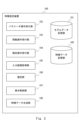
- 1 is a block diagram showing an example of a functional configuration of a feature setting device according to a first embodiment
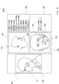
- FIG. 3 is a schematic diagram showing an example of a GUI screen displayed on the output device by the display control unit according to the first embodiment.
- 1 is a block diagram showing an example of a hardware configuration of a feature setting device according to a first embodiment
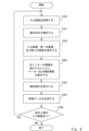
- FIG. 5 is a flowchart illustrating an example of the operation of the feature setting device according to the first embodiment.
- FIG. 7 is a schematic diagram showing an example of a GUI screen displayed on the output device by the display control unit according to the second embodiment.
- 7 is a flowchart illustrating an example of the operation of the feature setting device according to the second embodiment.
- FIG. 7 is a schematic diagram showing an example of a GUI screen displayed on an output device by a display control unit according to a modification of the second embodiment.
- FIG. 1 is a block diagram showing an example of the configuration of a feature setting device 1 according to an overview of the embodiment.
- the feature setting device 1 includes a display control section 2 and a movement operation reception section 3.
- the feature setting device 1 is a device used by a user to specify the position of a feature on the surface of a person's face (that is, the skin of the face).
- features that exist on the surface of a person's face include features that can be seen on the skin surface, such as moles, freckles, tattoos, birthmarks, wrinkles, dimples, scars, warts, bumps, skin irregularities, and areas of skin discoloration. be. These features serve as facial landmarks and can be used, for example, for face verification.
- Each component of the feature setting device 1 will be explained below.
- the display control unit 2 controls the first face image and the second face image to be displayed. More specifically, the first face image and the second face image are face images of the same person having different properties.
- the first face image and the second face image may be an image of a face facing in a first direction and an image of a face facing in a second direction.
- the first direction may be freely changeable.
- the first direction may be a variable direction.
- the display control unit 2 controls, for example, to display, as the first face image, an image of the face in a direction set based on the user's operation.
- the second direction may be a fixed direction.
- the second face image may be an image of a face facing forward.
- the first direction and the second direction may be different directions, and do not necessarily have the above-mentioned limitations.
- the movement operation accepting unit 3 accepts a pointer movement operation. Using a pointing device such as a mouse, the user points a pointer at an arbitrary position on the screen that includes the first face image and the second face image. The movement operation accepting unit 3 accepts such a pointer movement operation by the user via the input device.
- the display control unit 2 When the pointer on either the first face image or the second face image moves, the display control unit 2 displays a pointer on the other face image corresponding to the position of the moving pointer. Controls the display of markers in conjunction with the movement of the pointer. That is, if the position of the pointer according to the received movement operation is on the first face image, the display control unit 2 determines whether the position of the pointer according to the received movement operation is on the second face image and at the position pointed by the pointer. Execute processing to display markers in real time at positions where facial parts exist.
- the fact that the marker is displayed in real time does not mean that there is no tolerance for deviations in the display timing, but rather that the marker is displayed on the other image using the operation (movement) of the pointer on one image as a trigger.
- the display control unit 2 controls the display control unit 2 to display a position on the first face image where the pointer is located at the position pointed to by the pointer.
- display control of the marker on the other face image by the display control unit 2 may be performed only when the pointer is on the first face image, or when the pointer is on the second face image. It may be done only on.
- This marker is a display indicating where the provisional position of the feature is located on the other face image, when the position pointed by the pointer on one face image is set as the provisional position of the feature.
- the marker is a display that indicates a position on the other face image that is equivalent to the provisional position of the feature when the position pointed by the pointer on one face image is the provisional position of the feature. .
- the user uses such a feature setting device 1, the user performs an operation to determine the position pointed by the pointer as the position of a feature existing on the surface of the face.
- FIG. 2 is a schematic diagram illustrating the process of specifying the position of facial features 91 of a person 90 on a facial image 92.
- feature 91 is on the left facial surface of person 90.
- FIG. 2 if you try to specify the position of the feature 91 using only the front-facing face image 92, you may be able to specify the rough range 93 where the feature 91 may exist, but you will not be able to specify the exact position. Difficult to specify.
- the left facial surface on which the feature 91 exists corresponds to a facial surface tilted in the depth direction when drawing a face facing forward, and therefore the left facial surface is drawn in a compressed manner. In other words, it is difficult for the user to specify the exact position of the feature 91 on the narrowly drawn left facial surface.
- the position of the feature 91 is specified using a face image of the person 90 facing sideways instead of the face image 92, the left facial surface where the feature 91 is present will be drawn widely, so the position can be changed.
- the specification is relatively easy. However, when attempting to specify the position of the feature 91 using only a face image facing in one direction (for example, a face image facing sideways), it may be difficult to specify the position accurately.
- other parts may be facial components that are common to human faces, such as eyes, eyebrows, nose, mouth, ears, etc., or other parts whose positions have already been determined. It may be a feature.
- the positional relationship between the parts on the right facial surface and the feature 91 is easy to understand using the face image 92 of the face facing forward, but it is difficult to understand using only the face image facing to the side. Therefore, in order to specify an accurate position, it is preferable to use images of faces in different orientations. According to the feature setting device 1, as described above, since the first face image and the second face image are used, it is possible to specify an accurate position.
- the user can determine where the position pointed with the pointer in the first face image (second face image) is in the second face image (first face image).
- the position of the feature can be determined by checking in real time whether it corresponds to the feature. Therefore, after determining the position of a feature in a first face image (for example, an image of a face facing in a certain direction), this position is transferred to a second face image that has different characteristics from the first face image. (For example, an image of a face facing a different direction) can reduce the effort that would otherwise be required. In other words, it is possible to suppress the occurrence of a situation in which the user notices an error in the determined position and restarts the work. Therefore, according to the feature setting device 1, the user can accurately and efficiently specify the position of a feature on the surface of the face.
- the feature setting device 1 having the configuration shown in FIG. 1 has been described, but the aspect for obtaining the above effects is not limited to the device.
- similar effects can be obtained with a feature setting method that includes the above-described processing of the feature setting device 1, a program that performs the above-described processing of the feature setting device 1, or a non-transitory computer-readable medium in which the program is stored. be able to.
- FIG. 3 is a block diagram showing an example of the functional configuration of the feature setting device 100 according to the first embodiment.
- the feature setting device 100 is a device corresponding to the feature setting device 1 in FIG.
- a user uses the feature setting device 100 to input designating the position of a facial feature.
- the user specifies the position of the facial feature of the person shown in the facial image while viewing the facial image input to the feature setting device 100 and displayed on the screen.
- the user may specify the position of a person's facial features while looking at an actual person, or may specify the position of a person's facial features while looking at a photograph of the person printed on a paper medium. You may. In these cases, among the processes of the feature setting device 100 described later, the process of acquiring the input image, the process of displaying the input image, etc. can be omitted.
- the feature setting device 100 includes a model data storage section 101, a parameter operation reception section 102, a movement operation reception section 103, a confirmation operation reception section 104, an input image acquisition section 105, an estimation section 106, a display control section 107, a feature data generation section 108, and a feature data storage section 109. These will be explained below.
- the model data storage unit 101 stores three-dimensional data of a human face (head) generated in advance. That is, the model data storage unit 101 stores a three-dimensional model of the face. More specifically, the model data storage unit 101 stores data representing a three-dimensional CG (Computer Graphics) model of a human face. Note that the model data storage unit 101 may store three-dimensional data of the face of a fictional person, or may store three-dimensional data of the face of a real person. Specifically, the three-dimensional data of a fictional person's face has, for example, an average shape and facial components (eyes, eyebrows, nose, mouth, ears, etc.) at average positions. This is three-dimensional data of the average face, which is the arranged face.
- CG Computer Graphics
- model data storage unit 101 may store three-dimensional data of an average face for each predetermined group.
- the group may be a group based on gender, a group based on age, a group based on race, or the like.
- the model data storage unit 101 may store three-dimensional data of faces of a plurality of people as three-dimensional data of faces of real people. Note that the three-dimensional data is created in advance from, for example, data obtained by measuring or imaging a human face (head), and is stored in the model data storage unit 101.
- model data storage section 101 is included in the feature setting device 100, but the model data storage section 101 is communicably connected to the feature setting device 100 via a network or the like. It may also be realized in other devices.
- the parameter operation accepting unit 102 accepts an operation for changing parameters for drawing a first face image displayed in a first drawing area 901, which will be described later.
- the user uses an input device 151, which will be described later, to change parameters as necessary.
- This operation may be any operation for changing a parameter, may be an operation for inputting a parameter value, or may be a predetermined operation using a pointing device.
- parameters that can be changed by the user include a parameter for controlling the rotation of the three-dimensional model, a parameter for setting a viewpoint for drawing the three-dimensional model as a first face image, and a parameter for setting the first face image.
- the parameter that controls the rotation of the three-dimensional model is a parameter that rotates the three-dimensional model of the face in the model space.
- the parameters that control the rotation of the three-dimensional model include a parameter that controls rotation around the x-axis in model space, a parameter that controls rotation around the y-axis, and a parameter that controls rotation around the z-axis. including. Note that the parameters that control the rotation of the three-dimensional model do not need to be all of these, and may be only some of them.
- the parameters that control the rotation of the three-dimensional model it is possible to display a first face image in which a face facing an arbitrary direction is drawn. Therefore, user convenience is improved. For example, the user can display a face in the same orientation as the face in the input image as the first image, and then specify the position of the feature.
- the parameters for setting the viewpoint for drawing the three-dimensional model as the first face image are parameters set for the camera placed in the model space as a viewpoint for drawing.
- the parameters set for the camera include parameters for setting the camera position (that is, the coordinates of the camera in the model space), but are not limited thereto and may include other parameters.
- the parameters set for the camera may include parameters for setting the orientation of the camera in the model space, or parameters for setting the angle of view of the camera.
- the parameter that sets the placement position of the face in the first face image is a parameter that moves the drawn face in parallel.
- the parameters include a parameter that determines the position of the face in the horizontal direction (x-axis direction) and a parameter that determines the position of the face in the vertical direction (y-axis direction). Note that only one of the parameters may be used to set the placement position of the face.
- the parameters for setting the placement position of the face it is possible to display the first face image in which the face is drawn at an arbitrary position. Therefore, user convenience is improved. For example, the user can display a face depicted at the same position as the face depicted in the input image as the first image, and then specify the position of the feature.
- the movement operation reception unit 103 corresponds to the movement operation reception unit 3 in FIG.
- the movement operation accepting unit 103 accepts a pointer movement operation.
- the user points an arbitrary position on the GUI (Graphical User Interface) screen output under the control of the display control unit 107 using a pointer using an input device 151 (more specifically, a pointing device such as a mouse), which will be described later. point.
- This GUI screen includes a first drawing area 901 where a first face image is displayed and a second drawing area 902 where a second face image is displayed, as will be described later.
- the confirmation operation reception unit 104 accepts an operation to confirm the position pointed by the pointer as the position of a feature existing on the surface of the face.
- the user uses an input device 151, which will be described later, to perform an operation to determine the position of the feature. Specifically, the user determines the position of a person's facial feature by performing a predetermined operation while pointing the pointer at the position of the facial feature of the person on the face image displayed on the GUI screen.
- This operation may be any predetermined operation for determining the position of the feature, and may be an operation of clicking a predetermined button on a mouse, or an input operation of a predetermined key on a keyboard. It's okay.
- the operation for determining the position of the feature may be performed when the pointer is on the first face image, or may be performed when the pointer is on the second face image.
- the input image acquisition unit 105 acquires the face image (hereinafter also referred to as input image) input to the feature setting device 100. Specifically, the input image acquisition unit 105 acquires an image showing a person whose facial features are to be determined. That is, the input image acquisition unit 105 acquires an image showing the features on the surface of the face. Specifically, the input image is, for example, an image of a person photographed by an imaging device such as a camera. The input image is displayed on the GUI screen by the display control unit 107. While referring to the position of the face shown in the displayed input image and the surface features of the face, the user selects the relevant position on the first face image or the second face image displayed on the GUI screen. Specify the position of the feature using a pointer.
- the input image acquisition unit 105 may acquire multiple facial images of the same person as input images.
- the plurality of face images may have different face orientations.
- the display control unit 107 controls, for example, to display a plurality of face images of the same person side by side at the same time. Good too.
- the display control unit 107 may perform control so that a plurality of facial images of the same person are displayed in sequence on the GUI screen.
- the input image acquisition unit 105 may acquire the input image by receiving the input image from another device, or read it from a storage device built into the feature setting device 100 or a storage device connected to the feature setting device 100. The input image may be obtained by doing so.
- the estimation unit 106 estimates the direction in which the face of the input image acquired by the input image acquisition unit 105 is facing. That is, it is estimated which direction and how much the face shown in the input image is tilted from the front facing face.
- the estimation unit 106 may use a known image recognition technique to estimate the direction in which the face shown in the input image faces. For example, the estimation unit 106 estimates the direction in which the face shown in the input image acquired by the input image acquisition unit 105 is facing, using a machine learning model learned in advance by machine learning such as deep learning. The estimation result by the estimation unit 106 is used to determine the face orientation of the first face image displayed in the first drawing area 901.
- the estimation result by the estimation unit 106 is used to display an image of a face in the same orientation as the face of the input image as a first face image.
- the estimation result of the estimation unit 106 does not necessarily have to be used to determine the face orientation of the first face image.
- the estimation unit 106 may be omitted in the feature setting device 100.
- the display control section 107 corresponds to the display control section 2 in FIG. Processing is performed to display on the output device 150, which will be described later, a GUI screen that accepts input from the user specifying the position of a feature on the surface of a person's face.
- FIG. 4 is a schematic diagram showing an example of a GUI screen 900 displayed on the output device 150 by the display control unit 107. As shown in FIG. 4, the GUI screen 900 includes a first drawing area 901, a second drawing area 902, an input image display area 903, and a parameter display area 904. Further, the display control unit 107 controls the pointer 950 to be displayed at a position according to the movement operation accepted by the movement operation reception unit 103.
- the input image display area 903 is an area where the input image acquired by the input image acquisition unit 105 is displayed.
- the display control unit 107 controls the input image acquired by the input image acquisition unit 105 to be displayed in the input image display area 903. Note that when the input image acquisition unit 105 acquires a plurality of images of the same person, the display control unit 107 may display the plurality of images side by side in the input image display area 903. In the example shown in FIG. 4, an input image 930 of a person having a feature 91 on the cheek near the lower end of the left ear is displayed in the input image display area 903.
- the parameter display area 904 is an area where parameter values for drawing the first face image 910 are displayed.
- the display control unit 107 controls the parameter values used for drawing the first image currently displayed in the first drawing area 901 to be displayed in the parameter display area 904.
- the first drawing area 901 is an area where the first face image 910 is drawn and displayed.
- the display control unit 107 generates an image depicting a face facing in a first direction based on the three-dimensional data (three-dimensional model) of the face stored in the model data storage unit 101, and displays the generated image in the first direction. It is displayed in the drawing area 901 of.
- the model data storage unit 101 stores a plurality of three-dimensional models of faces
- the first face image 910 is generated using, for example, the three-dimensional model specified by the user.
- the user selects, from among the plurality of three-dimensional models, a three-dimensional model corresponding to the person whose facial features are to be determined.
- the first direction can be changed freely.
- the first direction is a variable direction, and can be freely changed by the user by changing the values of parameters for drawing.
- the display control unit 107 controls so that the image of the face in the direction set according to the operation received by the parameter operation reception unit 102 is displayed as the first face image 910 in the first drawing area 901 .
- the display control unit 107 draws the first face image 910 using stereographic projection. For example, the display control unit 107 arranges a viewpoint (camera) and a projection plane (plane) in a model space where a three-dimensional model exists, and projects the three-dimensional model onto the projection plane, thereby displaying the first face. Draw image 910.
- a viewpoint camera
- a projection plane plane
- the display control unit 107 may control the first face image to be displayed with the direction estimated by the estimation unit 106 as the first direction. That is, the display control unit 107 may generate an image in which the face facing the estimated direction is drawn based on the three-dimensional model, and display this image as the first image. In this way, by displaying the image of the face facing the direction estimated by the estimation unit 106, the image of the face facing the same direction as the face reflected in the input image is set as the first face image. can be displayed. Therefore, the user does not have to perform any parameter changing operation.
- the display control unit 107 may set the default image of the first image, that is, the initial image of the first image, to be an image of a face facing in the direction estimated by the estimation unit 106. Thereafter, when the parameter operation reception unit 102 receives a parameter change operation from the user, the display control unit 107 controls to draw a face image according to the operation and display it as the first face image. It's okay. For example, if the user determines that the default image (initial image) is not appropriate, the user performs an operation to change parameters in order to change the display of the first facial image to a desired image. In this way, the display control unit 107 controls the display of the first face image drawn according to parameters operable by the user. Therefore, the user can freely change the drawing of the face to make it easier to input features, improving convenience.
- the second drawing area 902 is an area where a second face image 920 is drawn and displayed.
- the display control unit 107 generates an image depicting a face facing in a second direction based on the three-dimensional data (three-dimensional model) of the face stored in the model data storage unit 101, and displays the generated image in the second direction. is displayed in the drawing area 902 of.
- the display control unit 107 generates the second facial image using the three-dimensional model used to generate the first facial image 910.
- the second direction is a fixed direction
- the second facial image 920 is specifically an image of a face facing forward.
- the display control unit 107 controls to display, in the second drawing area 902, an image obtained by developing the texture of the three-dimensional model into two dimensions as the second face image.
- the display control unit 107 uses the three-dimensional model to perform, for example, UV development processing, and generates a developed image of the cylindrically projected face as the second face image.
- a face image (like the second face image 920 in FIG. 4) that is drawn by projecting a three-dimensional model with the face facing forward onto a plane is Compared to the face image 92 in FIG. 2), the side portions of the face are drawn in an elongated manner.
- an image is displayed in which the side area of the face is drawn relatively widely. Therefore, even when specifying the position of features on the facial surface tilted in the depth direction (for example, the sides of the face) using a front-view face image, the user can specify the position within a relatively wide area. can be specified. Therefore, even in such a case, the user can easily specify an accurate position.
- the display control unit 107 controls the input image 930, the first face image 910, and the second face image 920 to be displayed side by side.
- the user can specify the position of a feature on the first face image 910 or the second face image 920 using the pointer 950 while referring to the input image 930. Therefore, it is possible to compare the position of the feature shown in the input image 930 with the position of the pointer 950 on the first face image 910 or the second face image 920 to determine the position of the feature. This improves convenience.
- the user performs an operation to move the pointer 950 on the first face image 910 or the second face image 920 in order to specify the position of the feature.
- This operation is accepted by the movement operation reception unit 103, as described above.
- the movement operation accepting unit 103 may accept the movement operation as follows. If the pointer 950 is present in a portion of the surface of the face whose drawing area is smaller than other portions of the surface of the face, the movement operation reception unit 103 changes the moving speed of the pointer 950 to the other portion of the face. It may be lowered than when pointer 950 exists.
- the movement operation reception unit 103 calculates the ratio of the amount of movement of the pointer to the amount of physical operation by the user in the other portion. may be lower than if the pointer existed in . More specifically, the movement operation reception unit 103 reduces the movement speed (movement amount) when the pointer 950 is present in a portion where the drawing area of the unit area is smaller than other portions.
- the unit area is an area of the surface (texture) of a three-dimensional model, and is an area having a unit area.
- the drawing area is the area of a region in the image drawn as the first face image 910 or the second face image 920.
- the drawing area is an index indicating how large a region having a unit area on the three-dimensional model is drawn in the first face image 910 or the second face image 920. Therefore, a portion whose drawing area is smaller than other portions can also be said to be a portion that is drawn smaller than the other portions.
- the portion corresponding to the front of the face has a smaller drawing area per unit area than the portion corresponding to the left side of the face. Therefore, for example, when the pointer 950 moves in an area on the first face image 910 in which a portion corresponding to the front of the face is drawn, the moving speed of the pointer 950 decreases.
- the portion corresponding to the side surface of the face has a smaller drawing area per unit area than the portion corresponding to the front surface of the face. Therefore, for example, when the pointer 950 moves in an area on the second face image 920 in which a portion corresponding to the side face of the face is drawn, the moving speed of the pointer 950 decreases.
- the moving speed of the pointer 950 decreases when specifying the position of a feature in a reduced and drawn area. Easy to make fine adjustments. Therefore, even when specifying the position of a feature in an area that is drawn in a compressed manner, the user can easily specify the position accurately.
- the movement operation reception unit 103 may control the movement speed of the pointer 950 described above only when the pointer 950 is on the first face image 910 or when the pointer 950 is on the second face image 920. You can do just that. For example, when the pointer 950 is on the second face image 920, the movement operation receiving unit 103 performs the above-mentioned movement speed control, and when the pointer 950 is on the first face image 910, the movement operation reception unit 103 performs the above-mentioned movement speed control. It is not necessary to control the movement speed. Further, whether or not to control the movement speed described above may be determined according to an instruction from the user.
- the display control unit 107 displays a pointer 950 on the other face image corresponding to the position of the moving pointer 950.
- the marker 951 is controlled to be displayed at the position in conjunction with the movement of the pointer 950. That is, when the pointer 950 exists on the first face image 910, the display control unit 107 moves the marker 951 in real time to a position on the second face image 920 that corresponds to the position of the pointer 950. control to display in conjunction with.
- the display control unit 107 places a marker 951 on the first face image 910 at a position corresponding to the position of the pointer 950. Control the linked display in real time.
- the position corresponding to the pointer 950 is a position on the face image where the pointer 950 does not exist, and is a position where the part of the face that exists at the position pointed to by the pointer 950 is drawn.
- the display control unit 107 may execute the above-described linked display of the marker 951 in real time only when the pointer 950 is present on the first face image 910, or may execute the linked display of the marker 951 in real time only when the pointer 950 is present on the first face image 910.
- pointer 950 It may be executed only if pointer 950 exists.
- the user is moving the pointer 950 over the second face image 920.
- the display control unit 107 controls to display a marker 951 on the first face image 910 in a portion corresponding to the portion pointed by the pointer 950.
- the display control unit 107 may also control the marker 952 to be displayed at the position indicated by the pointer 950.
- the marker 951 and the marker 952 are images in which one point is drawn, but the marker 951 and the marker 952 are not limited to this and may be other images.
- the marker 951 and the marker 952 may be images that imitate features.
- the display control unit 107 converts, for example, the position pointed by the pointer 950 on one of the facial images to the position in the three-dimensional model that is the basis of the facial image, and displays the image that is drawn based on the three-dimensional model. By calculating the position in the other face image, the drawing position of the marker 951 is specified.
- the user checks the position of the pointer 950 on the second face image 920 (the position of the marker 952) and the position of the marker 951 displayed in conjunction with the first face image 910, and 91 is specified on the second face image 920.
- This operation is accepted as a confirmation operation by the confirmation operation reception unit 104.
- the user may perform an operation to specify the position of the feature 91 on the first face image 910.
- the user checks the position of the pointer 950 on the first face image 910 (the position of the marker 952) and the position of the marker 951 displayed in conjunction with the second face image 920, and An operation is performed to specify the position of on the first face image 910.
- the user can confirm in real time that the position pointed by the pointer 950 in the image of a face in one orientation corresponds to the position in the image of the face in another orientation.
- the position of feature 91 can be determined. Therefore, the user can accurately and efficiently specify the position of the feature 91 on the surface of the face.
- the feature data generation unit 108 When the confirmation operation reception unit 104 receives an operation to confirm the position of the feature 91, the feature data generation unit 108 generates feature data that is data representing the position of the feature 91.
- the feature data may be, for example, data indicating positions in the three-dimensional model used to draw the first face image 910 and the second face image 920. That is, the feature data may be data indicating the position of a feature in a three-dimensional model.
- the feature data generation unit 108 generates feature data by converting the position pointed by the pointer 950 when the confirmation operation is performed into a position in the three-dimensional model.
- the feature data generation unit 108 stores the generated feature data in the feature data storage unit 109.
- the feature data storage unit 109 stores feature data generated by the feature data generation unit 108 based on input from the user. Note that in the configuration shown in FIG. 3, the feature data storage section 109 is included in the feature setting device 100, but the feature data storage section 109 is communicably connected to the feature setting device 100 via a network or the like. It may also be realized in other devices. Further, the feature data storage unit 109 may be configured as a database.
- the data stored in the feature data storage unit 109 can be used for any purpose.
- the purpose of the work for which the user specifies the position of a feature is arbitrary and is not limited to a specific purpose.
- the feature data may be used to match people using facial images. Specifically, it is possible to identify which of the known persons an unknown person corresponds to by comparing the position of the unknown person's facial features with the position of each of the facial features of multiple known persons.
- the feature setting device 100 may be used to enable this. In this case, this device may be used to pre-register the position of the feature of a known person in a database, or the device may be used to register the position of the feature of an unknown person to be compared with the position of the feature stored in the database.
- This device may be used for input into a verification system.
- feature data is not limited to image matching.
- feature data may be collected to generate new data from the feature data.
- feature data may be collected to generate feature location statistics. In this way, the purpose of the user specifying the position of a feature is arbitrary.
- FIG. 5 is a block diagram showing an example of the hardware configuration of the feature setting device 100.
- the feature setting device 100 includes an output device 150, an input device 151, a storage device 152, a memory 153, and a processor 154.
- the output device 150 is an output device such as a display that outputs information to the outside.
- the display may be, for example, a flat panel display such as a liquid crystal display, a plasma display, or an organic EL (Electro-Luminescence) display.
- the output device 150 displays the GUI provided by the display control unit 107.
- the input device 151 is a device for a user to input via a GUI, and is an input device including a pointing device. Examples of pointing devices include a mouse, trackball, touch panel, pen tablet, and the like. Input device 151 and output device 150 may be integrally configured as a touch panel.
- the input device 151 may include a device other than a pointing device, such as a keyboard.
- the storage device 152 is a nonvolatile storage device such as a hard disk or flash memory.
- the model data storage unit 101 and feature data storage unit 109 described above are realized by, for example, the storage device 152, but may be realized by other storage devices.
- the memory 153 is configured, for example, by a combination of volatile memory and nonvolatile memory.
- the memory 153 is used to store software (computer program) including one or more instructions executed by the processor 154, data used for various processes of the feature setting device 100, and the like.
- the processor 154 reads software (computer program) from the memory 153 and executes it to perform the processing of the feature setting device 100 described above.
- the processor 154 may be, for example, a microprocessor, an MPU (Micro Processor Unit), or a CPU (Central Processing Unit).
- Processor 154 may include multiple processors. In this way, the feature setting device 100 has the function of a computer.
- a program includes a set of instructions (or software code) that, when loaded into a computer, causes the computer to perform one or more functions described in the embodiments.
- the program may be stored on a non-transitory computer readable medium or a tangible storage medium.
- a computer readable medium or tangible storage medium may include random-access memory (RAM), read-only memory (ROM), flash memory, solid-state drive (SSD) or other memory technology, CD - including ROM, digital versatile disc (DVD), Blu-ray disc or other optical disc storage, magnetic cassette, magnetic tape, magnetic disc storage or other magnetic storage device.
- the program may be transmitted on a transitory computer-readable medium or a communication medium.
- transitory computer-readable or communication media includes electrical, optical, acoustic, or other forms of propagating signals.
- FIG. 6 is a flowchart showing an example of the operation of the feature setting device 100.
- the operation flow of the feature setting device 100 will be described below with reference to FIG.
- step S100 the input image acquisition unit 105 acquires an input image 930 in which a person's face having characteristics on the surface of the face is shown.
- step S101 the estimation unit 106 estimates the direction in which the face shown in the input image 930 acquired in step S100 is facing.
- step S102 the display control unit 107 controls the output device 150 to display a GUI including the input image 930, the first face image 910, and the second face image 920.
- the display control unit 107 controls to display, as the first face image 910, an image of the face facing in the direction estimated in step S101.
- the display control unit 107 may be controlled to display the first face image 910 drawn according to the specified parameters.
- step S103 the movement operation accepting unit 103 accepts a movement operation of the pointer 950.
- the display control unit 107 places a marker 951 on the other face image in real time. control to display in conjunction with. Note that, as described above, the display control unit 107 may further control to display the marker 952 at the position pointed by the pointer 950.
- step S104 the confirmation operation accepting unit 104 accepts an operation to confirm the position pointed by the pointer 950 as the position of a feature existing on the surface of the face.
- step S105 the feature data generation unit 108 generates feature data whose feature position is the position pointed by the pointer 950 when the confirmation operation is performed, and stores it in the feature data storage unit 109.
- step S106 the input image acquisition unit 105 determines whether there is an input image of the next person. That is, the input image acquisition unit 105 determines whether there is an input image of another person whose feature position should be specified. If there is an input image of another person, the process returns to step S100 and the above-described process is repeated. On the other hand, if there is no input image of another person, the process ends.
- Embodiment 1 has been described above.
- the user confirms in real time that the position pointed with the pointer 950 in a face image in a certain orientation corresponds to which position in the face image in a different orientation, and then sets the feature 91. position can be determined. Therefore, according to the feature setting device 100, the user can accurately and efficiently specify the position of a feature on the surface of the face.
- Embodiment 2 differs from Embodiment 1 in that information to enable more precise specification of the location of features is further displayed on the GUI.
- differences from Embodiment 1 will be specifically explained, and redundant explanations will be omitted as appropriate.
- the display control unit 107 according to the second embodiment differs from the display control unit 107 according to the first embodiment in that it further displays information indicating the positional relationship between the position pointed by the pointer and the facial components.
- the facial components refer to facial elements that are common to human faces, such as eyes, eyebrows, nose, mouth, and ears, but may also include features on the surface of the face.
- the display control unit 107 according to the second embodiment will be specifically described below.
- FIG. 7 is a schematic diagram showing an example of a GUI screen 900a displayed on the output device 150 by the display control unit 107 according to the second embodiment.
- the GUI screen 900a shown in FIG. 7 differs from the GUI screen 900 shown in FIG. 4 in that crosshairs 960 and 961 are additionally displayed.
- the display control unit 107 controls to display the crosshairs 960 and 961 as information representing the positional relationship between the position pointed by the pointer and the facial components.
- information representing the positional relationship between the position pointed by the pointer and the constituent elements of the face is also referred to as auxiliary information.
- the display control unit 107 further controls the display of crosshairs 960 and 961. Note that the display control unit 107 may control to display only one of the crosshairs 960 and 961.
- the crosshair 960 is centered at the position pointed by the pointer 950.
- the cross line 961 is a cross line centered at the position of the marker 951 displayed in conjunction with the pointer 950 on a face image different from the face image in which the pointer 950 is present. All of these cross lines are cross lines where a line in the vertical direction (vertical direction of the face) and a line in the horizontal direction (horizontal direction of the face) intersect.
- the two mutually intersecting lines forming the crosshair each have a predetermined length as the length from the center of the crosshair to the end of the line.
- this predetermined length is set to at least the length of the face so that it is easy to visually understand the positional relationship between the center of the crosshairs (that is, the intersection of two intersecting lines) and the facial components. It is preferable that the length is at least one-fourth of the length. Furthermore, in order to ensure that even if the pointer 950 is located at one end of the face, the crosshairs can reach the other end of the face, it is more preferable that the predetermined length described above is equal to or longer than the length of the face. .
- the length of the face refers to the length of the face in the vertical direction (vertical direction of the face), and the length of the face in the horizontal direction (horizontal direction of the face). In contrast, it refers to the length of the face in the horizontal direction (lateral direction of the face).
- FIG. 8 is a flowchart illustrating an example of the operation of the feature setting device 100 according to the second embodiment. As shown in FIG. 8, the flowchart shown here differs from the flowchart shown in FIG. 6 in that step S200 is executed instead of step S103. Hereinafter, points different from the flowchart shown in FIG. 6 will be explained.
- step S200 in addition to the processing in step S103 described above, auxiliary information is further displayed.
- the display control unit 107 controls the auxiliary information to be displayed in real time according to the position of the pointer 950. In the GUI example of FIG. 7, in step S200, the display control unit 107 further controls the GUI to display crosshairs 960 and 961.
- step S104 the process moves to step S104.
- the processing after step S104 is similar to the processing in the flowchart shown in FIG.
- Embodiment 2 has been described above.
- the display control unit 107 controls to further display information representing the positional relationship between the position pointed by the pointer and the constituent elements of the face. Therefore, the user can specify the position of the feature after confirming the positional relationship between the feature and the constituent elements of the face. Therefore, it is possible to specify the position of the feature more accurately.
- the display control unit 107 displays crosshairs 960 and 961 on the GUI. Therefore, by comparing the positions of the lines forming the crosshairs and the positions of other components, the user can determine the relative deviation between the provisional position of the feature 91 indicated by the pointer 950 and the positions of the other components. The size can be easily confirmed visually. For example, in the example shown in FIG.
- the user uses crosshairs 960 and 961 to compare the position of the nose with the provisional position of the feature 91 indicated by the pointer 950, thereby determining the relative positional relationship between the two. can be easily confirmed visually.
- the display control unit 107 displays marks similar to the crosshairs 960 and 961 on the input image 930 in accordance with instructions from the user via the input device 151. A crosshair may also be displayed.
- FIG. 9 is a schematic diagram showing an example of a GUI screen 900b displayed on the output device 150 by the display control unit 107 according to a modification of the second embodiment.
- the distance between the position pointed by the pointer 950 and the position of a predetermined component of the face is displayed in a distance information display area 905 as auxiliary information.
- the distance from the outer corner of the left eye to the position pointed to by the pointer 950 and the distance from the position below the left nose to the position pointed to by the pointer 950 are displayed as auxiliary information.
- the predetermined component of the face refers to a predetermined component among the above-mentioned components of the face.
- the eyes and nose are cited as examples of predetermined components, but the distance may be displayed using other components of the face.
- the display control unit 107 may control to display the distance between the position pointed by the pointer 950 and the position of a predetermined component of the face.
- the model data storage unit 101 stores a three-dimensional model including position information for each component. Then, the display control unit 107 calculates the distance between the position pointed by the pointer 950 and the position of the component on the face image using the position information for each component, and displays the calculated distance on the GUI. According to such auxiliary information, the distance between the position of the face component and the provisional position of the feature can be clearly confirmed, so the user can accurately confirm the relative positional relationship between the two.
- a line connecting the position pointed by the pointer 950 and the position of a predetermined component of the face is displayed as auxiliary information.
- a line 970 connecting the position of the left corner of the eye and the position pointed by the pointer 950, and a line 971 connecting the position below the left nose and the position pointed to by the pointer 950 are displayed as auxiliary information.
- the display control unit 107 may control to display a line connecting the position pointed by the pointer 950 and the position of a predetermined component of the face.
- the model data storage unit 101 stores a three-dimensional model including position information for each component. According to such auxiliary information, the slope of the lines 970 and 971 allows the user to visually confirm the direction from the position of the face component to the provisional position of the feature, and thus the relative positional relationship between the two can be determined. It can be easily confirmed.
- the display control unit 107 may control to display auxiliary information about the positional relationship between a predetermined component and the pointer 950, or display information about the positional relationship between the component specified by the user and the pointer 950. It may also be controlled to display auxiliary information. Note that, as shown in FIG. 9, the display control unit 107 preferably displays auxiliary information for a plurality of components. That is, it is preferable that the display control unit 107 displays auxiliary information regarding the positional relationship between each of the plurality of components and the pointer 950. This is because such a display allows the user to determine the position of the feature after comparing the positional relationship between each component and the pointer 950.
- the relative position of the feature with respect to the position of the first component e.g., the left corner of the eye
- the relative position of the feature with respect to the position of the second component e.g., the left lower nose
- the position of the feature can be determined by comparing it with the actual position. More specifically, for example, the user can determine the position of the feature after confirming that the distance between the second component and the feature is shorter than the distance between the first component and the feature. Further, the user can determine the position of the feature after comparing the direction of the feature with respect to the first component and the direction of the feature with respect to the second component.
- FIG. 9 shows an example in which auxiliary information indicating the positional relationship between the pointer 950 and the component on the face image where the pointer 950 is present is displayed
- the display control unit 107 displays the marker 951 and the marker 951.
- control may be performed to display auxiliary information indicating the positional relationship with the component on the face image where the face image exists.
- the display control unit 107 may display only a part of the crosshair, the distance between the pointer and the component, and the line connecting the pointer and the component as auxiliary information, or may display a combination of these. good.
- Display control means for controlling display of a first face image and a second face image; and a movement operation reception means for accepting a pointer movement operation, When the pointer on one of the first face image and the second face image moves, the display control means displays an image on the other face image corresponding to the position of the moving pointer.
- a feature setting device that controls to display a marker at a position in conjunction with movement of the pointer.
- the display control means is configured to use movement of the pointer on either one of the first face image and the second face image as a trigger, and to move the marker on the other face image so that the marker points to the pointer on the other face image.
- the feature setting device according to supplementary note 1 which controls the display to correspond to the position of the feature setting device.
- the feature setting device according to appendix 1 or 2 wherein the display control means displays information representing a positional relationship between a position pointed by the pointer and a facial component.
- the feature setting device according to appendix 3 wherein the information includes a distance between a position pointed by the pointer and a position of a predetermined component of the face.
- the feature setting device according to any one of Supplementary Notes 1 to 7, wherein the pointer is lowered than when the pointer exists.
- (Appendix 9) further comprising parameter operation accepting means for accepting an operation for changing parameters for drawing the first face image, At least the first face image is drawn based on a three-dimensional model of a face,
- the parameter is a parameter that controls rotation of the three-dimensional model, a parameter that sets a viewpoint for drawing the three-dimensional model as the first face image, or a position of the face in the first face image. contains at least one of the parameters that set the
- the feature setting device according to any one of Supplementary Notes 1 to 8, wherein the display control means controls to display the first face image drawn according to the parameters.
- the first face image is an image of a face facing in a first direction
- (Appendix 11) further comprising input image acquisition means for acquiring the input facial image
- Appendix 12 an input image acquisition means for acquiring an input face image; further comprising estimation means for estimating the direction in which the face of the inputted face image is facing,
- the feature setting device according to appendix 10 wherein the display control means controls to display the first face image with the estimated direction as the first direction.
- Appendix 13 The feature setting device according to any one of Supplementary Notes 1 to 12, wherein the second face image is an image obtained by two-dimensionally developing the texture of a three-dimensional model of a face.
- (Appendix 14) Displaying a first face image and a second face image, Accepts pointer movement operations, When the pointer on either the first face image or the second face image moves, the pointer is moved to a position on the other face image corresponding to the position of the moving pointer. How to set the feature to display the marker in conjunction with the movement of. (Appendix 15) a display control step of controlling to display the first face image and the second face image; a movement operation reception step for accepting a pointer movement operation; make the computer run In the display control step, when the pointer on one of the first face image and the second face image moves, the pointer on the other face image corresponding to the position of the moving pointer is moved.
- a non-transitory computer-readable medium storing a program for controlling display of a marker at a position in conjunction with movement of the pointer.
Landscapes
- Engineering & Computer Science (AREA)
- Theoretical Computer Science (AREA)
- General Engineering & Computer Science (AREA)
- Physics & Mathematics (AREA)
- General Physics & Mathematics (AREA)
- Software Systems (AREA)
- Computer Graphics (AREA)
- Computer Hardware Design (AREA)
- Human Computer Interaction (AREA)
- Remote Sensing (AREA)
- Radar, Positioning & Navigation (AREA)
- Architecture (AREA)
- Image Processing (AREA)
- Processing Or Creating Images (AREA)
Priority Applications (4)
| Application Number | Priority Date | Filing Date | Title |
|---|---|---|---|
| PCT/JP2022/016143 WO2023188159A1 (ja) | 2022-03-30 | 2022-03-30 | 特徴設定装置、特徴設定方法、及び非一時的なコンピュータ可読媒体 |
| EP22935304.0A EP4502956A1 (en) | 2022-03-30 | 2022-03-30 | Feature setting device, feature setting method, and non-transitory computer-readable medium |
| US18/839,844 US20250173987A1 (en) | 2022-03-30 | 2022-03-30 | Feature setting apparatus, feature setting method, and non-transitory computer readable medium |
| JP2024510932A JP7740519B2 (ja) | 2022-03-30 | 2022-03-30 | 特徴設定装置、特徴設定方法、及びプログラム |
Applications Claiming Priority (1)
| Application Number | Priority Date | Filing Date | Title |
|---|---|---|---|
| PCT/JP2022/016143 WO2023188159A1 (ja) | 2022-03-30 | 2022-03-30 | 特徴設定装置、特徴設定方法、及び非一時的なコンピュータ可読媒体 |
Publications (1)
| Publication Number | Publication Date |
|---|---|
| WO2023188159A1 true WO2023188159A1 (ja) | 2023-10-05 |
Family
ID=88199769
Family Applications (1)
| Application Number | Title | Priority Date | Filing Date |
|---|---|---|---|
| PCT/JP2022/016143 Ceased WO2023188159A1 (ja) | 2022-03-30 | 2022-03-30 | 特徴設定装置、特徴設定方法、及び非一時的なコンピュータ可読媒体 |
Country Status (4)
| Country | Link |
|---|---|
| US (1) | US20250173987A1 (https=) |
| EP (1) | EP4502956A1 (https=) |
| JP (1) | JP7740519B2 (https=) |
| WO (1) | WO2023188159A1 (https=) |
Citations (3)
| Publication number | Priority date | Publication date | Assignee | Title |
|---|---|---|---|---|
| JP2017126240A (ja) * | 2016-01-15 | 2017-07-20 | 日立Geニュークリア・エナジー株式会社 | 3次元モデル表示システムおよび表示方法 |
| WO2021084662A1 (ja) * | 2019-10-30 | 2021-05-06 | 日本電気株式会社 | 照合支援装置、照合支援方法、及びコンピュータ読み取り可能な記録媒体 |
| WO2021084661A1 (ja) | 2019-10-30 | 2021-05-06 | 日本電気株式会社 | 照合支援装置、照合支援方法、及びコンピュータ読み取り可能な記録媒体 |
-
2022
- 2022-03-30 EP EP22935304.0A patent/EP4502956A1/en not_active Withdrawn
- 2022-03-30 WO PCT/JP2022/016143 patent/WO2023188159A1/ja not_active Ceased
- 2022-03-30 US US18/839,844 patent/US20250173987A1/en active Pending
- 2022-03-30 JP JP2024510932A patent/JP7740519B2/ja active Active
Patent Citations (3)
| Publication number | Priority date | Publication date | Assignee | Title |
|---|---|---|---|---|
| JP2017126240A (ja) * | 2016-01-15 | 2017-07-20 | 日立Geニュークリア・エナジー株式会社 | 3次元モデル表示システムおよび表示方法 |
| WO2021084662A1 (ja) * | 2019-10-30 | 2021-05-06 | 日本電気株式会社 | 照合支援装置、照合支援方法、及びコンピュータ読み取り可能な記録媒体 |
| WO2021084661A1 (ja) | 2019-10-30 | 2021-05-06 | 日本電気株式会社 | 照合支援装置、照合支援方法、及びコンピュータ読み取り可能な記録媒体 |
Also Published As
| Publication number | Publication date |
|---|---|
| JPWO2023188159A1 (https=) | 2023-10-05 |
| JP7740519B2 (ja) | 2025-09-17 |
| EP4502956A1 (en) | 2025-02-05 |
| US20250173987A1 (en) | 2025-05-29 |
Similar Documents
| Publication | Publication Date | Title |
|---|---|---|
| CN108369742B (zh) | 使用传感器融合的经优化对象扫描 | |
| KR101556992B1 (ko) | 얼굴 성형 시뮬레이션을 이용한 3차원 스캔 시스템 | |
| JP6723061B2 (ja) | 情報処理装置、情報処理装置の制御方法およびプログラム | |
| US20170106540A1 (en) | Information processing apparatus, information processing method, and program | |
| US20160148411A1 (en) | Method of making a personalized animatable mesh | |
| US20200258193A1 (en) | Information processing apparatus, information processing method, and storage medium | |
| US11403830B2 (en) | Image processing device, image processing method, and program | |
| JP2009278456A (ja) | 映像表示装置 | |
| JP2017194301A (ja) | 顔形状測定装置及び方法 | |
| TW201606574A (zh) | 操作畫面顯示裝置、操作畫面顯示方法以及非暫時性之記錄媒體 | |
| JP7063165B2 (ja) | 計測装置、計測方法及び計測プログラム | |
| JP2002015310A (ja) | 点群に面をフィッティングする方法およびモデリング装置 | |
| WO2023188159A1 (ja) | 特徴設定装置、特徴設定方法、及び非一時的なコンピュータ可読媒体 | |
| CN119048594A (zh) | 一种用于脑磁自动配准的多目视觉系统 | |
| JP2002015338A (ja) | モデルの変形方法およびモデリング装置 | |
| JP7029253B2 (ja) | 情報処理装置及びその方法 | |
| JP4962470B2 (ja) | 眼領域検出装置、及びプログラム | |
| JP7321029B2 (ja) | キャリブレーション装置及びその制御方法及びプログラム及び記憶媒体 | |
| JP4838411B2 (ja) | 形状モデルの生成方法 | |
| JP4924747B2 (ja) | 標準モデルの変形方法およびモデリング装置 | |
| JP6948801B2 (ja) | 情報処理装置、情報処理装置の制御方法及びプログラム | |
| KR20160096393A (ko) | 맵핑형 3차원 상호작용 장치 및 방법 | |
| JP2021168750A (ja) | 情報処理装置、情報処理方法、及びプログラム | |
| JP2002015309A (ja) | 形状モデルの生成方法および装置 | |
| JP2002015307A (ja) | 形状モデルの生成方法 |
Legal Events
| Date | Code | Title | Description |
|---|---|---|---|
| 121 | Ep: the epo has been informed by wipo that ep was designated in this application |
Ref document number: 22935304 Country of ref document: EP Kind code of ref document: A1 |
|
| ENP | Entry into the national phase |
Ref document number: 2024510932 Country of ref document: JP Kind code of ref document: A |
|
| WWE | Wipo information: entry into national phase |
Ref document number: 18839844 Country of ref document: US |
|
| WWE | Wipo information: entry into national phase |
Ref document number: 2022935304 Country of ref document: EP |
|
| NENP | Non-entry into the national phase |
Ref country code: DE |
|
| ENP | Entry into the national phase |
Ref document number: 2022935304 Country of ref document: EP Effective date: 20241030 |
|
| WWP | Wipo information: published in national office |
Ref document number: 18839844 Country of ref document: US |