WO2023188159A1 - Feature setting device, feature setting method, and non-transitory computer-readable medium - Google Patents
Feature setting device, feature setting method, and non-transitory computer-readable medium Download PDFInfo
- Publication number
- WO2023188159A1 WO2023188159A1 PCT/JP2022/016143 JP2022016143W WO2023188159A1 WO 2023188159 A1 WO2023188159 A1 WO 2023188159A1 JP 2022016143 W JP2022016143 W JP 2022016143W WO 2023188159 A1 WO2023188159 A1 WO 2023188159A1
- Authority
- WO
- WIPO (PCT)
- Prior art keywords
- face
- pointer
- face image
- image
- feature
- Prior art date
Links
- 238000000034 method Methods 0.000 title abstract description 18
- 230000001815 facial effect Effects 0.000 claims abstract description 65
- 239000003550 marker Substances 0.000 claims abstract description 44
- 239000000470 constituent Substances 0.000 claims description 5
- 238000013500 data storage Methods 0.000 description 27
- 238000010586 diagram Methods 0.000 description 14
- 238000012545 processing Methods 0.000 description 12
- 230000008569 process Effects 0.000 description 11
- 238000012790 confirmation Methods 0.000 description 10
- 210000000887 face Anatomy 0.000 description 10
- 210000001331 nose Anatomy 0.000 description 8
- 210000001508 eye Anatomy 0.000 description 7
- 230000008859 change Effects 0.000 description 6
- 238000012986 modification Methods 0.000 description 5
- 230000004048 modification Effects 0.000 description 5
- 230000007423 decrease Effects 0.000 description 4
- 210000005069 ears Anatomy 0.000 description 3
- 210000004709 eyebrow Anatomy 0.000 description 3
- 210000000214 mouth Anatomy 0.000 description 3
- 208000032544 Cicatrix Diseases 0.000 description 2
- 238000004891 communication Methods 0.000 description 2
- 238000004590 computer program Methods 0.000 description 2
- 230000000694 effects Effects 0.000 description 2
- 238000005401 electroluminescence Methods 0.000 description 2
- 230000006870 function Effects 0.000 description 2
- 210000003128 head Anatomy 0.000 description 2
- 238000003384 imaging method Methods 0.000 description 2
- 238000010801 machine learning Methods 0.000 description 2
- 230000003287 optical effect Effects 0.000 description 2
- 231100000241 scar Toxicity 0.000 description 2
- 230000037387 scars Effects 0.000 description 2
- 238000012795 verification Methods 0.000 description 2
- 206010004950 Birth mark Diseases 0.000 description 1
- 206010014970 Ephelides Diseases 0.000 description 1
- 208000003351 Melanosis Diseases 0.000 description 1
- 206010040829 Skin discolouration Diseases 0.000 description 1
- 238000013135 deep learning Methods 0.000 description 1
- 238000011161 development Methods 0.000 description 1
- 230000018109 developmental process Effects 0.000 description 1
- 238000005516 engineering process Methods 0.000 description 1
- 230000027648 face development Effects 0.000 description 1
- 230000010365 information processing Effects 0.000 description 1
- 239000004973 liquid crystal related substance Substances 0.000 description 1
- 230000001902 propagating effect Effects 0.000 description 1
- 230000004044 response Effects 0.000 description 1
- 230000037370 skin discoloration Effects 0.000 description 1
- 230000000007 visual effect Effects 0.000 description 1
- 230000037303 wrinkles Effects 0.000 description 1
Images


Classifications
-
- G—PHYSICS
- G06—COMPUTING; CALCULATING OR COUNTING
- G06T—IMAGE DATA PROCESSING OR GENERATION, IN GENERAL
- G06T19/00—Manipulating 3D models or images for computer graphics
-
- G—PHYSICS
- G06—COMPUTING; CALCULATING OR COUNTING
- G06V—IMAGE OR VIDEO RECOGNITION OR UNDERSTANDING
- G06V40/00—Recognition of biometric, human-related or animal-related patterns in image or video data
- G06V40/10—Human or animal bodies, e.g. vehicle occupants or pedestrians; Body parts, e.g. hands
- G06V40/16—Human faces, e.g. facial parts, sketches or expressions
Definitions
- This disclosure relates to a feature setting device, a feature setting method, and a program.
- a user who is a database creator may specify the positions of the facial features of each of a plurality of known people.
- a user who is in charge of a search may input the position of the facial features of the person to be identified into the matching system.
- Patent Document 1 discloses a user interface for inputting the positions of features on the surface of a person's face when matching the person's face.
- the user views either the reference face three-dimensional image or the reference face development image and performs an input to determine the position of the feature.
- the feature is also reflected in the reference face developed image.
- the position of the feature is determined using multiple facial images of the same person with different characteristics. By checking this, the user can more accurately determine whether the position designated as the position of the feature is appropriate. For example, by confirming the position of the feature using a plurality of face images with different face orientations, the user can more accurately determine whether the position designated as the position of the feature is appropriate.
- the user interface described in Patent Document 1 for example, when the position of a feature with respect to a reference face three-dimensional image of a face facing diagonally is determined, the feature is also reflected in a reference face developed image of a face facing forward. Is displayed.
- the user can check whether the position designated as the position of the feature is appropriate using a plurality of face images with different face orientations.
- the reference face developed image of the face facing forward is displayed. Therefore, if the user who has checked such a reference face developed image determines that the specified position is not appropriate, the user needs to re-specify the position. This leads to a decrease in work efficiency.
- one of the objectives of the embodiments disclosed in this specification is to provide a feature setting device that allows a user to accurately and efficiently specify the position of a feature on the surface of a face. , a feature setting method, and a program.
- the feature setting device includes: Display control means for controlling display of a first face image and a second face image; and a movement operation reception means for accepting a pointer movement operation, When the pointer on one of the first face image and the second face image moves, the display control means displays an image on the other face image corresponding to the position of the moving pointer. The marker is controlled to be displayed at the position in conjunction with the movement of the pointer.
- the program according to the third aspect of this disclosure is: a display control step of controlling to display the first face image and the second face image; causing the computer to execute a movement operation reception step of accepting a pointer movement operation;
- a display control step when the pointer on one of the first face image and the second face image moves, the pointer on the other face image corresponding to the position of the moving pointer is moved.
- the marker is controlled to be displayed at the position in conjunction with the movement of the pointer.
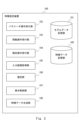
- FIG. 1 is a block diagram illustrating an example of the configuration of a feature setting device according to an overview of an embodiment
- FIG. FIG. 2 is a schematic diagram illustrating a process of specifying the position of a person's facial features on a facial image.
- 1 is a block diagram showing an example of a functional configuration of a feature setting device according to a first embodiment
- FIG. 3 is a schematic diagram showing an example of a GUI screen displayed on the output device by the display control unit according to the first embodiment.
- 1 is a block diagram showing an example of a hardware configuration of a feature setting device according to a first embodiment
- FIG. 5 is a flowchart illustrating an example of the operation of the feature setting device according to the first embodiment.
- FIG. 7 is a schematic diagram showing an example of a GUI screen displayed on the output device by the display control unit according to the second embodiment.
- 7 is a flowchart illustrating an example of the operation of the feature setting device according to the second embodiment.
- FIG. 7 is a schematic diagram showing an example of a GUI screen displayed on an output device by a display control unit according to a modification of the second embodiment.
- FIG. 1 is a block diagram showing an example of the configuration of a feature setting device 1 according to an overview of the embodiment.
- the feature setting device 1 includes a display control section 2 and a movement operation reception section 3.
- the feature setting device 1 is a device used by a user to specify the position of a feature on the surface of a person's face (that is, the skin of the face).
- features that exist on the surface of a person's face include features that can be seen on the skin surface, such as moles, freckles, tattoos, birthmarks, wrinkles, dimples, scars, warts, bumps, skin irregularities, and areas of skin discoloration. be. These features serve as facial landmarks and can be used, for example, for face verification.
- Each component of the feature setting device 1 will be explained below.
- the display control unit 2 controls the first face image and the second face image to be displayed. More specifically, the first face image and the second face image are face images of the same person having different properties.
- the first face image and the second face image may be an image of a face facing in a first direction and an image of a face facing in a second direction.
- the first direction may be freely changeable.
- the first direction may be a variable direction.
- the display control unit 2 controls, for example, to display, as the first face image, an image of the face in a direction set based on the user's operation.
- the second direction may be a fixed direction.
- the second face image may be an image of a face facing forward.
- the first direction and the second direction may be different directions, and do not necessarily have the above-mentioned limitations.
- the movement operation accepting unit 3 accepts a pointer movement operation. Using a pointing device such as a mouse, the user points a pointer at an arbitrary position on the screen that includes the first face image and the second face image. The movement operation accepting unit 3 accepts such a pointer movement operation by the user via the input device.
- the display control unit 2 When the pointer on either the first face image or the second face image moves, the display control unit 2 displays a pointer on the other face image corresponding to the position of the moving pointer. Controls the display of markers in conjunction with the movement of the pointer. That is, if the position of the pointer according to the received movement operation is on the first face image, the display control unit 2 determines whether the position of the pointer according to the received movement operation is on the second face image and at the position pointed by the pointer. Execute processing to display markers in real time at positions where facial parts exist.
- the fact that the marker is displayed in real time does not mean that there is no tolerance for deviations in the display timing, but rather that the marker is displayed on the other image using the operation (movement) of the pointer on one image as a trigger.
- the display control unit 2 controls the display control unit 2 to display a position on the first face image where the pointer is located at the position pointed to by the pointer.
- display control of the marker on the other face image by the display control unit 2 may be performed only when the pointer is on the first face image, or when the pointer is on the second face image. It may be done only on.
- This marker is a display indicating where the provisional position of the feature is located on the other face image, when the position pointed by the pointer on one face image is set as the provisional position of the feature.
- the marker is a display that indicates a position on the other face image that is equivalent to the provisional position of the feature when the position pointed by the pointer on one face image is the provisional position of the feature. .
- the user uses such a feature setting device 1, the user performs an operation to determine the position pointed by the pointer as the position of a feature existing on the surface of the face.
- FIG. 2 is a schematic diagram illustrating the process of specifying the position of facial features 91 of a person 90 on a facial image 92.
- feature 91 is on the left facial surface of person 90.
- FIG. 2 if you try to specify the position of the feature 91 using only the front-facing face image 92, you may be able to specify the rough range 93 where the feature 91 may exist, but you will not be able to specify the exact position. Difficult to specify.
- the left facial surface on which the feature 91 exists corresponds to a facial surface tilted in the depth direction when drawing a face facing forward, and therefore the left facial surface is drawn in a compressed manner. In other words, it is difficult for the user to specify the exact position of the feature 91 on the narrowly drawn left facial surface.
- the position of the feature 91 is specified using a face image of the person 90 facing sideways instead of the face image 92, the left facial surface where the feature 91 is present will be drawn widely, so the position can be changed.
- the specification is relatively easy. However, when attempting to specify the position of the feature 91 using only a face image facing in one direction (for example, a face image facing sideways), it may be difficult to specify the position accurately.
- other parts may be facial components that are common to human faces, such as eyes, eyebrows, nose, mouth, ears, etc., or other parts whose positions have already been determined. It may be a feature.
- the positional relationship between the parts on the right facial surface and the feature 91 is easy to understand using the face image 92 of the face facing forward, but it is difficult to understand using only the face image facing to the side. Therefore, in order to specify an accurate position, it is preferable to use images of faces in different orientations. According to the feature setting device 1, as described above, since the first face image and the second face image are used, it is possible to specify an accurate position.
- the user can determine where the position pointed with the pointer in the first face image (second face image) is in the second face image (first face image).
- the position of the feature can be determined by checking in real time whether it corresponds to the feature. Therefore, after determining the position of a feature in a first face image (for example, an image of a face facing in a certain direction), this position is transferred to a second face image that has different characteristics from the first face image. (For example, an image of a face facing a different direction) can reduce the effort that would otherwise be required. In other words, it is possible to suppress the occurrence of a situation in which the user notices an error in the determined position and restarts the work. Therefore, according to the feature setting device 1, the user can accurately and efficiently specify the position of a feature on the surface of the face.
- the feature setting device 1 having the configuration shown in FIG. 1 has been described, but the aspect for obtaining the above effects is not limited to the device.
- similar effects can be obtained with a feature setting method that includes the above-described processing of the feature setting device 1, a program that performs the above-described processing of the feature setting device 1, or a non-transitory computer-readable medium in which the program is stored. be able to.
- FIG. 3 is a block diagram showing an example of the functional configuration of the feature setting device 100 according to the first embodiment.
- the feature setting device 100 is a device corresponding to the feature setting device 1 in FIG.
- a user uses the feature setting device 100 to input designating the position of a facial feature.
- the user specifies the position of the facial feature of the person shown in the facial image while viewing the facial image input to the feature setting device 100 and displayed on the screen.
- the user may specify the position of a person's facial features while looking at an actual person, or may specify the position of a person's facial features while looking at a photograph of the person printed on a paper medium. You may. In these cases, among the processes of the feature setting device 100 described later, the process of acquiring the input image, the process of displaying the input image, etc. can be omitted.
- the feature setting device 100 includes a model data storage section 101, a parameter operation reception section 102, a movement operation reception section 103, a confirmation operation reception section 104, an input image acquisition section 105, an estimation section 106, a display control section 107, a feature data generation section 108, and a feature data storage section 109. These will be explained below.
- the model data storage unit 101 stores three-dimensional data of a human face (head) generated in advance. That is, the model data storage unit 101 stores a three-dimensional model of the face. More specifically, the model data storage unit 101 stores data representing a three-dimensional CG (Computer Graphics) model of a human face. Note that the model data storage unit 101 may store three-dimensional data of the face of a fictional person, or may store three-dimensional data of the face of a real person. Specifically, the three-dimensional data of a fictional person's face has, for example, an average shape and facial components (eyes, eyebrows, nose, mouth, ears, etc.) at average positions. This is three-dimensional data of the average face, which is the arranged face.
- CG Computer Graphics
- model data storage unit 101 may store three-dimensional data of an average face for each predetermined group.
- the group may be a group based on gender, a group based on age, a group based on race, or the like.
- the model data storage unit 101 may store three-dimensional data of faces of a plurality of people as three-dimensional data of faces of real people. Note that the three-dimensional data is created in advance from, for example, data obtained by measuring or imaging a human face (head), and is stored in the model data storage unit 101.
- model data storage section 101 is included in the feature setting device 100, but the model data storage section 101 is communicably connected to the feature setting device 100 via a network or the like. It may also be realized in other devices.
- the parameter operation accepting unit 102 accepts an operation for changing parameters for drawing a first face image displayed in a first drawing area 901, which will be described later.
- the user uses an input device 151, which will be described later, to change parameters as necessary.
- This operation may be any operation for changing a parameter, may be an operation for inputting a parameter value, or may be a predetermined operation using a pointing device.
- parameters that can be changed by the user include a parameter for controlling the rotation of the three-dimensional model, a parameter for setting a viewpoint for drawing the three-dimensional model as a first face image, and a parameter for setting the first face image.
- the parameter that controls the rotation of the three-dimensional model is a parameter that rotates the three-dimensional model of the face in the model space.
- the parameters that control the rotation of the three-dimensional model include a parameter that controls rotation around the x-axis in model space, a parameter that controls rotation around the y-axis, and a parameter that controls rotation around the z-axis. including. Note that the parameters that control the rotation of the three-dimensional model do not need to be all of these, and may be only some of them.
- the parameters that control the rotation of the three-dimensional model it is possible to display a first face image in which a face facing an arbitrary direction is drawn. Therefore, user convenience is improved. For example, the user can display a face in the same orientation as the face in the input image as the first image, and then specify the position of the feature.
- the parameters for setting the viewpoint for drawing the three-dimensional model as the first face image are parameters set for the camera placed in the model space as a viewpoint for drawing.
- the parameters set for the camera include parameters for setting the camera position (that is, the coordinates of the camera in the model space), but are not limited thereto and may include other parameters.
- the parameters set for the camera may include parameters for setting the orientation of the camera in the model space, or parameters for setting the angle of view of the camera.
- the parameter that sets the placement position of the face in the first face image is a parameter that moves the drawn face in parallel.
- the parameters include a parameter that determines the position of the face in the horizontal direction (x-axis direction) and a parameter that determines the position of the face in the vertical direction (y-axis direction). Note that only one of the parameters may be used to set the placement position of the face.
- the parameters for setting the placement position of the face it is possible to display the first face image in which the face is drawn at an arbitrary position. Therefore, user convenience is improved. For example, the user can display a face depicted at the same position as the face depicted in the input image as the first image, and then specify the position of the feature.
- the movement operation reception unit 103 corresponds to the movement operation reception unit 3 in FIG.
- the movement operation accepting unit 103 accepts a pointer movement operation.
- the user points an arbitrary position on the GUI (Graphical User Interface) screen output under the control of the display control unit 107 using a pointer using an input device 151 (more specifically, a pointing device such as a mouse), which will be described later. point.
- This GUI screen includes a first drawing area 901 where a first face image is displayed and a second drawing area 902 where a second face image is displayed, as will be described later.
- the confirmation operation reception unit 104 accepts an operation to confirm the position pointed by the pointer as the position of a feature existing on the surface of the face.
- the user uses an input device 151, which will be described later, to perform an operation to determine the position of the feature. Specifically, the user determines the position of a person's facial feature by performing a predetermined operation while pointing the pointer at the position of the facial feature of the person on the face image displayed on the GUI screen.
- This operation may be any predetermined operation for determining the position of the feature, and may be an operation of clicking a predetermined button on a mouse, or an input operation of a predetermined key on a keyboard. It's okay.
- the operation for determining the position of the feature may be performed when the pointer is on the first face image, or may be performed when the pointer is on the second face image.
- the input image acquisition unit 105 acquires the face image (hereinafter also referred to as input image) input to the feature setting device 100. Specifically, the input image acquisition unit 105 acquires an image showing a person whose facial features are to be determined. That is, the input image acquisition unit 105 acquires an image showing the features on the surface of the face. Specifically, the input image is, for example, an image of a person photographed by an imaging device such as a camera. The input image is displayed on the GUI screen by the display control unit 107. While referring to the position of the face shown in the displayed input image and the surface features of the face, the user selects the relevant position on the first face image or the second face image displayed on the GUI screen. Specify the position of the feature using a pointer.
- the input image acquisition unit 105 may acquire multiple facial images of the same person as input images.
- the plurality of face images may have different face orientations.
- the display control unit 107 controls, for example, to display a plurality of face images of the same person side by side at the same time. Good too.
- the display control unit 107 may perform control so that a plurality of facial images of the same person are displayed in sequence on the GUI screen.
- the input image acquisition unit 105 may acquire the input image by receiving the input image from another device, or read it from a storage device built into the feature setting device 100 or a storage device connected to the feature setting device 100. The input image may be obtained by doing so.
- the estimation unit 106 estimates the direction in which the face of the input image acquired by the input image acquisition unit 105 is facing. That is, it is estimated which direction and how much the face shown in the input image is tilted from the front facing face.
- the estimation unit 106 may use a known image recognition technique to estimate the direction in which the face shown in the input image faces. For example, the estimation unit 106 estimates the direction in which the face shown in the input image acquired by the input image acquisition unit 105 is facing, using a machine learning model learned in advance by machine learning such as deep learning. The estimation result by the estimation unit 106 is used to determine the face orientation of the first face image displayed in the first drawing area 901.
- the estimation result by the estimation unit 106 is used to display an image of a face in the same orientation as the face of the input image as a first face image.
- the estimation result of the estimation unit 106 does not necessarily have to be used to determine the face orientation of the first face image.
- the estimation unit 106 may be omitted in the feature setting device 100.
- the display control section 107 corresponds to the display control section 2 in FIG. Processing is performed to display on the output device 150, which will be described later, a GUI screen that accepts input from the user specifying the position of a feature on the surface of a person's face.
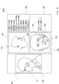
- FIG. 4 is a schematic diagram showing an example of a GUI screen 900 displayed on the output device 150 by the display control unit 107. As shown in FIG. 4, the GUI screen 900 includes a first drawing area 901, a second drawing area 902, an input image display area 903, and a parameter display area 904. Further, the display control unit 107 controls the pointer 950 to be displayed at a position according to the movement operation accepted by the movement operation reception unit 103.
- the input image display area 903 is an area where the input image acquired by the input image acquisition unit 105 is displayed.
- the display control unit 107 controls the input image acquired by the input image acquisition unit 105 to be displayed in the input image display area 903. Note that when the input image acquisition unit 105 acquires a plurality of images of the same person, the display control unit 107 may display the plurality of images side by side in the input image display area 903. In the example shown in FIG. 4, an input image 930 of a person having a feature 91 on the cheek near the lower end of the left ear is displayed in the input image display area 903.
- the parameter display area 904 is an area where parameter values for drawing the first face image 910 are displayed.
- the display control unit 107 controls the parameter values used for drawing the first image currently displayed in the first drawing area 901 to be displayed in the parameter display area 904.
- the first drawing area 901 is an area where the first face image 910 is drawn and displayed.
- the display control unit 107 generates an image depicting a face facing in a first direction based on the three-dimensional data (three-dimensional model) of the face stored in the model data storage unit 101, and displays the generated image in the first direction. It is displayed in the drawing area 901 of.
- the model data storage unit 101 stores a plurality of three-dimensional models of faces
- the first face image 910 is generated using, for example, the three-dimensional model specified by the user.
- the user selects, from among the plurality of three-dimensional models, a three-dimensional model corresponding to the person whose facial features are to be determined.
- the first direction can be changed freely.
- the first direction is a variable direction, and can be freely changed by the user by changing the values of parameters for drawing.
- the display control unit 107 controls so that the image of the face in the direction set according to the operation received by the parameter operation reception unit 102 is displayed as the first face image 910 in the first drawing area 901 .
- the display control unit 107 draws the first face image 910 using stereographic projection. For example, the display control unit 107 arranges a viewpoint (camera) and a projection plane (plane) in a model space where a three-dimensional model exists, and projects the three-dimensional model onto the projection plane, thereby displaying the first face. Draw image 910.
- a viewpoint camera
- a projection plane plane
- the display control unit 107 may control the first face image to be displayed with the direction estimated by the estimation unit 106 as the first direction. That is, the display control unit 107 may generate an image in which the face facing the estimated direction is drawn based on the three-dimensional model, and display this image as the first image. In this way, by displaying the image of the face facing the direction estimated by the estimation unit 106, the image of the face facing the same direction as the face reflected in the input image is set as the first face image. can be displayed. Therefore, the user does not have to perform any parameter changing operation.
- the display control unit 107 may set the default image of the first image, that is, the initial image of the first image, to be an image of a face facing in the direction estimated by the estimation unit 106. Thereafter, when the parameter operation reception unit 102 receives a parameter change operation from the user, the display control unit 107 controls to draw a face image according to the operation and display it as the first face image. It's okay. For example, if the user determines that the default image (initial image) is not appropriate, the user performs an operation to change parameters in order to change the display of the first facial image to a desired image. In this way, the display control unit 107 controls the display of the first face image drawn according to parameters operable by the user. Therefore, the user can freely change the drawing of the face to make it easier to input features, improving convenience.
- the second drawing area 902 is an area where a second face image 920 is drawn and displayed.
- the display control unit 107 generates an image depicting a face facing in a second direction based on the three-dimensional data (three-dimensional model) of the face stored in the model data storage unit 101, and displays the generated image in the second direction. is displayed in the drawing area 902 of.
- the display control unit 107 generates the second facial image using the three-dimensional model used to generate the first facial image 910.
- the second direction is a fixed direction
- the second facial image 920 is specifically an image of a face facing forward.
- the display control unit 107 controls to display, in the second drawing area 902, an image obtained by developing the texture of the three-dimensional model into two dimensions as the second face image.
- the display control unit 107 uses the three-dimensional model to perform, for example, UV development processing, and generates a developed image of the cylindrically projected face as the second face image.
- a face image (like the second face image 920 in FIG. 4) that is drawn by projecting a three-dimensional model with the face facing forward onto a plane is Compared to the face image 92 in FIG. 2), the side portions of the face are drawn in an elongated manner.
- an image is displayed in which the side area of the face is drawn relatively widely. Therefore, even when specifying the position of features on the facial surface tilted in the depth direction (for example, the sides of the face) using a front-view face image, the user can specify the position within a relatively wide area. can be specified. Therefore, even in such a case, the user can easily specify an accurate position.
- the display control unit 107 controls the input image 930, the first face image 910, and the second face image 920 to be displayed side by side.
- the user can specify the position of a feature on the first face image 910 or the second face image 920 using the pointer 950 while referring to the input image 930. Therefore, it is possible to compare the position of the feature shown in the input image 930 with the position of the pointer 950 on the first face image 910 or the second face image 920 to determine the position of the feature. This improves convenience.
- the user performs an operation to move the pointer 950 on the first face image 910 or the second face image 920 in order to specify the position of the feature.
- This operation is accepted by the movement operation reception unit 103, as described above.
- the movement operation accepting unit 103 may accept the movement operation as follows. If the pointer 950 is present in a portion of the surface of the face whose drawing area is smaller than other portions of the surface of the face, the movement operation reception unit 103 changes the moving speed of the pointer 950 to the other portion of the face. It may be lowered than when pointer 950 exists.
- the movement operation reception unit 103 calculates the ratio of the amount of movement of the pointer to the amount of physical operation by the user in the other portion. may be lower than if the pointer existed in . More specifically, the movement operation reception unit 103 reduces the movement speed (movement amount) when the pointer 950 is present in a portion where the drawing area of the unit area is smaller than other portions.
- the unit area is an area of the surface (texture) of a three-dimensional model, and is an area having a unit area.
- the drawing area is the area of a region in the image drawn as the first face image 910 or the second face image 920.
- the drawing area is an index indicating how large a region having a unit area on the three-dimensional model is drawn in the first face image 910 or the second face image 920. Therefore, a portion whose drawing area is smaller than other portions can also be said to be a portion that is drawn smaller than the other portions.
- the portion corresponding to the front of the face has a smaller drawing area per unit area than the portion corresponding to the left side of the face. Therefore, for example, when the pointer 950 moves in an area on the first face image 910 in which a portion corresponding to the front of the face is drawn, the moving speed of the pointer 950 decreases.
- the portion corresponding to the side surface of the face has a smaller drawing area per unit area than the portion corresponding to the front surface of the face. Therefore, for example, when the pointer 950 moves in an area on the second face image 920 in which a portion corresponding to the side face of the face is drawn, the moving speed of the pointer 950 decreases.
- the moving speed of the pointer 950 decreases when specifying the position of a feature in a reduced and drawn area. Easy to make fine adjustments. Therefore, even when specifying the position of a feature in an area that is drawn in a compressed manner, the user can easily specify the position accurately.
- the movement operation reception unit 103 may control the movement speed of the pointer 950 described above only when the pointer 950 is on the first face image 910 or when the pointer 950 is on the second face image 920. You can do just that. For example, when the pointer 950 is on the second face image 920, the movement operation receiving unit 103 performs the above-mentioned movement speed control, and when the pointer 950 is on the first face image 910, the movement operation reception unit 103 performs the above-mentioned movement speed control. It is not necessary to control the movement speed. Further, whether or not to control the movement speed described above may be determined according to an instruction from the user.
- the display control unit 107 displays a pointer 950 on the other face image corresponding to the position of the moving pointer 950.
- the marker 951 is controlled to be displayed at the position in conjunction with the movement of the pointer 950. That is, when the pointer 950 exists on the first face image 910, the display control unit 107 moves the marker 951 in real time to a position on the second face image 920 that corresponds to the position of the pointer 950. control to display in conjunction with.
- the display control unit 107 places a marker 951 on the first face image 910 at a position corresponding to the position of the pointer 950. Control the linked display in real time.
- the position corresponding to the pointer 950 is a position on the face image where the pointer 950 does not exist, and is a position where the part of the face that exists at the position pointed to by the pointer 950 is drawn.
- the display control unit 107 may execute the above-described linked display of the marker 951 in real time only when the pointer 950 is present on the first face image 910, or may execute the linked display of the marker 951 in real time only when the pointer 950 is present on the first face image 910.
- pointer 950 It may be executed only if pointer 950 exists.
- the user is moving the pointer 950 over the second face image 920.
- the display control unit 107 controls to display a marker 951 on the first face image 910 in a portion corresponding to the portion pointed by the pointer 950.
- the display control unit 107 may also control the marker 952 to be displayed at the position indicated by the pointer 950.
- the marker 951 and the marker 952 are images in which one point is drawn, but the marker 951 and the marker 952 are not limited to this and may be other images.
- the marker 951 and the marker 952 may be images that imitate features.
- the display control unit 107 converts, for example, the position pointed by the pointer 950 on one of the facial images to the position in the three-dimensional model that is the basis of the facial image, and displays the image that is drawn based on the three-dimensional model. By calculating the position in the other face image, the drawing position of the marker 951 is specified.
- the user checks the position of the pointer 950 on the second face image 920 (the position of the marker 952) and the position of the marker 951 displayed in conjunction with the first face image 910, and 91 is specified on the second face image 920.
- This operation is accepted as a confirmation operation by the confirmation operation reception unit 104.
- the user may perform an operation to specify the position of the feature 91 on the first face image 910.
- the user checks the position of the pointer 950 on the first face image 910 (the position of the marker 952) and the position of the marker 951 displayed in conjunction with the second face image 920, and An operation is performed to specify the position of on the first face image 910.
- the user can confirm in real time that the position pointed by the pointer 950 in the image of a face in one orientation corresponds to the position in the image of the face in another orientation.
- the position of feature 91 can be determined. Therefore, the user can accurately and efficiently specify the position of the feature 91 on the surface of the face.
- the feature data generation unit 108 When the confirmation operation reception unit 104 receives an operation to confirm the position of the feature 91, the feature data generation unit 108 generates feature data that is data representing the position of the feature 91.
- the feature data may be, for example, data indicating positions in the three-dimensional model used to draw the first face image 910 and the second face image 920. That is, the feature data may be data indicating the position of a feature in a three-dimensional model.
- the feature data generation unit 108 generates feature data by converting the position pointed by the pointer 950 when the confirmation operation is performed into a position in the three-dimensional model.
- the feature data generation unit 108 stores the generated feature data in the feature data storage unit 109.
- the feature data storage unit 109 stores feature data generated by the feature data generation unit 108 based on input from the user. Note that in the configuration shown in FIG. 3, the feature data storage section 109 is included in the feature setting device 100, but the feature data storage section 109 is communicably connected to the feature setting device 100 via a network or the like. It may also be realized in other devices. Further, the feature data storage unit 109 may be configured as a database.
- the data stored in the feature data storage unit 109 can be used for any purpose.
- the purpose of the work for which the user specifies the position of a feature is arbitrary and is not limited to a specific purpose.
- the feature data may be used to match people using facial images. Specifically, it is possible to identify which of the known persons an unknown person corresponds to by comparing the position of the unknown person's facial features with the position of each of the facial features of multiple known persons.
- the feature setting device 100 may be used to enable this. In this case, this device may be used to pre-register the position of the feature of a known person in a database, or the device may be used to register the position of the feature of an unknown person to be compared with the position of the feature stored in the database.
- This device may be used for input into a verification system.
- feature data is not limited to image matching.
- feature data may be collected to generate new data from the feature data.
- feature data may be collected to generate feature location statistics. In this way, the purpose of the user specifying the position of a feature is arbitrary.
- FIG. 5 is a block diagram showing an example of the hardware configuration of the feature setting device 100.
- the feature setting device 100 includes an output device 150, an input device 151, a storage device 152, a memory 153, and a processor 154.
- the output device 150 is an output device such as a display that outputs information to the outside.
- the display may be, for example, a flat panel display such as a liquid crystal display, a plasma display, or an organic EL (Electro-Luminescence) display.
- the output device 150 displays the GUI provided by the display control unit 107.
- the input device 151 is a device for a user to input via a GUI, and is an input device including a pointing device. Examples of pointing devices include a mouse, trackball, touch panel, pen tablet, and the like. Input device 151 and output device 150 may be integrally configured as a touch panel.
- the input device 151 may include a device other than a pointing device, such as a keyboard.
- the storage device 152 is a nonvolatile storage device such as a hard disk or flash memory.
- the model data storage unit 101 and feature data storage unit 109 described above are realized by, for example, the storage device 152, but may be realized by other storage devices.
- the memory 153 is configured, for example, by a combination of volatile memory and nonvolatile memory.
- the memory 153 is used to store software (computer program) including one or more instructions executed by the processor 154, data used for various processes of the feature setting device 100, and the like.
- the processor 154 reads software (computer program) from the memory 153 and executes it to perform the processing of the feature setting device 100 described above.
- the processor 154 may be, for example, a microprocessor, an MPU (Micro Processor Unit), or a CPU (Central Processing Unit).
- Processor 154 may include multiple processors. In this way, the feature setting device 100 has the function of a computer.
- a program includes a set of instructions (or software code) that, when loaded into a computer, causes the computer to perform one or more functions described in the embodiments.
- the program may be stored on a non-transitory computer readable medium or a tangible storage medium.
- a computer readable medium or tangible storage medium may include random-access memory (RAM), read-only memory (ROM), flash memory, solid-state drive (SSD) or other memory technology, CD - including ROM, digital versatile disc (DVD), Blu-ray disc or other optical disc storage, magnetic cassette, magnetic tape, magnetic disc storage or other magnetic storage device.
- the program may be transmitted on a transitory computer-readable medium or a communication medium.
- transitory computer-readable or communication media includes electrical, optical, acoustic, or other forms of propagating signals.
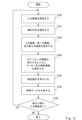
- FIG. 6 is a flowchart showing an example of the operation of the feature setting device 100.
- the operation flow of the feature setting device 100 will be described below with reference to FIG.
- step S100 the input image acquisition unit 105 acquires an input image 930 in which a person's face having characteristics on the surface of the face is shown.
- step S101 the estimation unit 106 estimates the direction in which the face shown in the input image 930 acquired in step S100 is facing.
- step S102 the display control unit 107 controls the output device 150 to display a GUI including the input image 930, the first face image 910, and the second face image 920.
- the display control unit 107 controls to display, as the first face image 910, an image of the face facing in the direction estimated in step S101.
- the display control unit 107 may be controlled to display the first face image 910 drawn according to the specified parameters.
- step S103 the movement operation accepting unit 103 accepts a movement operation of the pointer 950.
- the display control unit 107 places a marker 951 on the other face image in real time. control to display in conjunction with. Note that, as described above, the display control unit 107 may further control to display the marker 952 at the position pointed by the pointer 950.
- step S104 the confirmation operation accepting unit 104 accepts an operation to confirm the position pointed by the pointer 950 as the position of a feature existing on the surface of the face.
- step S105 the feature data generation unit 108 generates feature data whose feature position is the position pointed by the pointer 950 when the confirmation operation is performed, and stores it in the feature data storage unit 109.
- step S106 the input image acquisition unit 105 determines whether there is an input image of the next person. That is, the input image acquisition unit 105 determines whether there is an input image of another person whose feature position should be specified. If there is an input image of another person, the process returns to step S100 and the above-described process is repeated. On the other hand, if there is no input image of another person, the process ends.
- Embodiment 1 has been described above.
- the user confirms in real time that the position pointed with the pointer 950 in a face image in a certain orientation corresponds to which position in the face image in a different orientation, and then sets the feature 91. position can be determined. Therefore, according to the feature setting device 100, the user can accurately and efficiently specify the position of a feature on the surface of the face.
- Embodiment 2 differs from Embodiment 1 in that information to enable more precise specification of the location of features is further displayed on the GUI.
- differences from Embodiment 1 will be specifically explained, and redundant explanations will be omitted as appropriate.
- the display control unit 107 according to the second embodiment differs from the display control unit 107 according to the first embodiment in that it further displays information indicating the positional relationship between the position pointed by the pointer and the facial components.
- the facial components refer to facial elements that are common to human faces, such as eyes, eyebrows, nose, mouth, and ears, but may also include features on the surface of the face.
- the display control unit 107 according to the second embodiment will be specifically described below.
- FIG. 7 is a schematic diagram showing an example of a GUI screen 900a displayed on the output device 150 by the display control unit 107 according to the second embodiment.
- the GUI screen 900a shown in FIG. 7 differs from the GUI screen 900 shown in FIG. 4 in that crosshairs 960 and 961 are additionally displayed.
- the display control unit 107 controls to display the crosshairs 960 and 961 as information representing the positional relationship between the position pointed by the pointer and the facial components.
- information representing the positional relationship between the position pointed by the pointer and the constituent elements of the face is also referred to as auxiliary information.
- the display control unit 107 further controls the display of crosshairs 960 and 961. Note that the display control unit 107 may control to display only one of the crosshairs 960 and 961.
- the crosshair 960 is centered at the position pointed by the pointer 950.
- the cross line 961 is a cross line centered at the position of the marker 951 displayed in conjunction with the pointer 950 on a face image different from the face image in which the pointer 950 is present. All of these cross lines are cross lines where a line in the vertical direction (vertical direction of the face) and a line in the horizontal direction (horizontal direction of the face) intersect.
- the two mutually intersecting lines forming the crosshair each have a predetermined length as the length from the center of the crosshair to the end of the line.
- this predetermined length is set to at least the length of the face so that it is easy to visually understand the positional relationship between the center of the crosshairs (that is, the intersection of two intersecting lines) and the facial components. It is preferable that the length is at least one-fourth of the length. Furthermore, in order to ensure that even if the pointer 950 is located at one end of the face, the crosshairs can reach the other end of the face, it is more preferable that the predetermined length described above is equal to or longer than the length of the face. .
- the length of the face refers to the length of the face in the vertical direction (vertical direction of the face), and the length of the face in the horizontal direction (horizontal direction of the face). In contrast, it refers to the length of the face in the horizontal direction (lateral direction of the face).
- FIG. 8 is a flowchart illustrating an example of the operation of the feature setting device 100 according to the second embodiment. As shown in FIG. 8, the flowchart shown here differs from the flowchart shown in FIG. 6 in that step S200 is executed instead of step S103. Hereinafter, points different from the flowchart shown in FIG. 6 will be explained.
- step S200 in addition to the processing in step S103 described above, auxiliary information is further displayed.
- the display control unit 107 controls the auxiliary information to be displayed in real time according to the position of the pointer 950. In the GUI example of FIG. 7, in step S200, the display control unit 107 further controls the GUI to display crosshairs 960 and 961.
- step S104 the process moves to step S104.
- the processing after step S104 is similar to the processing in the flowchart shown in FIG.
- Embodiment 2 has been described above.
- the display control unit 107 controls to further display information representing the positional relationship between the position pointed by the pointer and the constituent elements of the face. Therefore, the user can specify the position of the feature after confirming the positional relationship between the feature and the constituent elements of the face. Therefore, it is possible to specify the position of the feature more accurately.
- the display control unit 107 displays crosshairs 960 and 961 on the GUI. Therefore, by comparing the positions of the lines forming the crosshairs and the positions of other components, the user can determine the relative deviation between the provisional position of the feature 91 indicated by the pointer 950 and the positions of the other components. The size can be easily confirmed visually. For example, in the example shown in FIG.
- the user uses crosshairs 960 and 961 to compare the position of the nose with the provisional position of the feature 91 indicated by the pointer 950, thereby determining the relative positional relationship between the two. can be easily confirmed visually.
- the display control unit 107 displays marks similar to the crosshairs 960 and 961 on the input image 930 in accordance with instructions from the user via the input device 151. A crosshair may also be displayed.
- FIG. 9 is a schematic diagram showing an example of a GUI screen 900b displayed on the output device 150 by the display control unit 107 according to a modification of the second embodiment.
- the distance between the position pointed by the pointer 950 and the position of a predetermined component of the face is displayed in a distance information display area 905 as auxiliary information.
- the distance from the outer corner of the left eye to the position pointed to by the pointer 950 and the distance from the position below the left nose to the position pointed to by the pointer 950 are displayed as auxiliary information.
- the predetermined component of the face refers to a predetermined component among the above-mentioned components of the face.
- the eyes and nose are cited as examples of predetermined components, but the distance may be displayed using other components of the face.
- the display control unit 107 may control to display the distance between the position pointed by the pointer 950 and the position of a predetermined component of the face.
- the model data storage unit 101 stores a three-dimensional model including position information for each component. Then, the display control unit 107 calculates the distance between the position pointed by the pointer 950 and the position of the component on the face image using the position information for each component, and displays the calculated distance on the GUI. According to such auxiliary information, the distance between the position of the face component and the provisional position of the feature can be clearly confirmed, so the user can accurately confirm the relative positional relationship between the two.
- a line connecting the position pointed by the pointer 950 and the position of a predetermined component of the face is displayed as auxiliary information.
- a line 970 connecting the position of the left corner of the eye and the position pointed by the pointer 950, and a line 971 connecting the position below the left nose and the position pointed to by the pointer 950 are displayed as auxiliary information.
- the display control unit 107 may control to display a line connecting the position pointed by the pointer 950 and the position of a predetermined component of the face.
- the model data storage unit 101 stores a three-dimensional model including position information for each component. According to such auxiliary information, the slope of the lines 970 and 971 allows the user to visually confirm the direction from the position of the face component to the provisional position of the feature, and thus the relative positional relationship between the two can be determined. It can be easily confirmed.
- the display control unit 107 may control to display auxiliary information about the positional relationship between a predetermined component and the pointer 950, or display information about the positional relationship between the component specified by the user and the pointer 950. It may also be controlled to display auxiliary information. Note that, as shown in FIG. 9, the display control unit 107 preferably displays auxiliary information for a plurality of components. That is, it is preferable that the display control unit 107 displays auxiliary information regarding the positional relationship between each of the plurality of components and the pointer 950. This is because such a display allows the user to determine the position of the feature after comparing the positional relationship between each component and the pointer 950.
- the relative position of the feature with respect to the position of the first component e.g., the left corner of the eye
- the relative position of the feature with respect to the position of the second component e.g., the left lower nose
- the position of the feature can be determined by comparing it with the actual position. More specifically, for example, the user can determine the position of the feature after confirming that the distance between the second component and the feature is shorter than the distance between the first component and the feature. Further, the user can determine the position of the feature after comparing the direction of the feature with respect to the first component and the direction of the feature with respect to the second component.
- FIG. 9 shows an example in which auxiliary information indicating the positional relationship between the pointer 950 and the component on the face image where the pointer 950 is present is displayed
- the display control unit 107 displays the marker 951 and the marker 951.
- control may be performed to display auxiliary information indicating the positional relationship with the component on the face image where the face image exists.
- the display control unit 107 may display only a part of the crosshair, the distance between the pointer and the component, and the line connecting the pointer and the component as auxiliary information, or may display a combination of these. good.
- Display control means for controlling display of a first face image and a second face image; and a movement operation reception means for accepting a pointer movement operation, When the pointer on one of the first face image and the second face image moves, the display control means displays an image on the other face image corresponding to the position of the moving pointer.
- a feature setting device that controls to display a marker at a position in conjunction with movement of the pointer.
- the display control means is configured to use movement of the pointer on either one of the first face image and the second face image as a trigger, and to move the marker on the other face image so that the marker points to the pointer on the other face image.
- the feature setting device according to supplementary note 1 which controls the display to correspond to the position of the feature setting device.
- the feature setting device according to appendix 1 or 2 wherein the display control means displays information representing a positional relationship between a position pointed by the pointer and a facial component.
- the feature setting device according to appendix 3 wherein the information includes a distance between a position pointed by the pointer and a position of a predetermined component of the face.
- the feature setting device according to any one of Supplementary Notes 1 to 7, wherein the pointer is lowered than when the pointer exists.
- (Appendix 9) further comprising parameter operation accepting means for accepting an operation for changing parameters for drawing the first face image, At least the first face image is drawn based on a three-dimensional model of a face,
- the parameter is a parameter that controls rotation of the three-dimensional model, a parameter that sets a viewpoint for drawing the three-dimensional model as the first face image, or a position of the face in the first face image. contains at least one of the parameters that set the
- the feature setting device according to any one of Supplementary Notes 1 to 8, wherein the display control means controls to display the first face image drawn according to the parameters.
- the first face image is an image of a face facing in a first direction
- (Appendix 11) further comprising input image acquisition means for acquiring the input facial image
- Appendix 12 an input image acquisition means for acquiring an input face image; further comprising estimation means for estimating the direction in which the face of the inputted face image is facing,
- the feature setting device according to appendix 10 wherein the display control means controls to display the first face image with the estimated direction as the first direction.
- Appendix 13 The feature setting device according to any one of Supplementary Notes 1 to 12, wherein the second face image is an image obtained by two-dimensionally developing the texture of a three-dimensional model of a face.
- (Appendix 14) Displaying a first face image and a second face image, Accepts pointer movement operations, When the pointer on either the first face image or the second face image moves, the pointer is moved to a position on the other face image corresponding to the position of the moving pointer. How to set the feature to display the marker in conjunction with the movement of. (Appendix 15) a display control step of controlling to display the first face image and the second face image; a movement operation reception step for accepting a pointer movement operation; make the computer run In the display control step, when the pointer on one of the first face image and the second face image moves, the pointer on the other face image corresponding to the position of the moving pointer is moved.
- a non-transitory computer-readable medium storing a program for controlling display of a marker at a position in conjunction with movement of the pointer.
Abstract
Provided are a feature setting device, a feature setting method, and a program capable of accurately and efficiently performing a task in which a user specifies the position of a feature on the surface of a face. A feature setting device (1) includes: a display control unit (2) that performs control so as to display a first facial image and a second facial image side by side; and a movement operation reception unit (3) that receives a movement operation of a pointer. If the pointer on one of the first facial image and the second facial image moves, the display control unit (2) performs control to display a marker, in conjunction with the movement of the pointer, at a position on the other facial image and corresponding to a position of the pointer that is moving.
Description
この開示は、特徴設定装置、特徴設定方法、及びプログラムに関する。
This disclosure relates to a feature setting device, a feature setting method, and a program.
顔認証などの分野において、人の顔の画像を用いた情報処理を行うための準備として、人の顔の表面に存在する、ほくろ、しみ、傷などの特徴の位置をユーザが指定する作業が行われることがある。例えば、顔画像を用いて人物を特定する照合システムのデータベースを作成するために、データベース作成者であるユーザが既知の複数の人物のそれぞれの顔の表面の特徴の位置を指定することがある。また、例えば、照合システムにより顔画像を用いて人物を特定するために、検索担当者であるユーザが、特定すべき人物の顔の表面の特徴の位置を照合システムに入力することがある。例えば、特許文献1は、人の顔の照合の際に、人の顔の表面の特徴の位置を入力するためのユーザインタフェースを開示している。このユーザインタフェースでは、ユーザは、基準顔三次元画像又は基準顔展開画像のいずれか一方を見て、特徴の位置を確定する入力を行なう。また、このユーザインタフェースでは、基準顔三次元画像に対する特徴の位置が確定すると、基準顔展開画像にも当該特徴が反映される。
In fields such as face recognition, in preparation for information processing using images of people's faces, users have to specify the locations of features such as moles, spots, and scars on the surface of a person's face. Sometimes it is done. For example, in order to create a database for a matching system that uses facial images to identify people, a user who is a database creator may specify the positions of the facial features of each of a plurality of known people. Further, for example, in order to identify a person using a facial image using a matching system, a user who is in charge of a search may input the position of the facial features of the person to be identified into the matching system. For example, Patent Document 1 discloses a user interface for inputting the positions of features on the surface of a person's face when matching the person's face. In this user interface, the user views either the reference face three-dimensional image or the reference face development image and performs an input to determine the position of the feature. Furthermore, in this user interface, once the position of a feature with respect to the reference face three-dimensional image is determined, the feature is also reflected in the reference face developed image.
ある人物の顔の表面に存在する特徴の位置を、当該特徴が表されていない顔画像に対して指定する場合、同一の人物についての異なる性質を有する複数の顔画像を用いて当該特徴の位置を確認することで、ユーザは当該特徴の位置として指定する位置が適切であるかをより精確に判断できる。例えば、顔の向きが異なる複数の顔画像を用いて当該特徴の位置を確認することで、ユーザは当該特徴の位置として指定する位置が適切であるかをより精確に判断できる。特許文献1に記載されたユーザインタフェースでは、例えば、斜めを向いた顔の基準顔三次元画像に対する特徴の位置が確定すると、正面を向いた顔の基準顔展開画像にも当該特徴が反映されて表示される。このため、ユーザは、当該特徴の位置として指定した位置が適切であるかを顔の向きが異なる複数の顔画像を用いて確認することができる。しかしながら、このユーザインタフェースでは、ユーザにより特徴の位置が一旦確定されてから、正面を向いた顔の基準顔展開画像が表示される。このため、そのような基準顔展開画像を確認したユーザが、指定した位置が適切でないと判断した場合には、ユーザは、再度、位置を指定し直す作業を行なう必要がある。これにより作業効率の低下を招いてしまう。
When specifying the position of a feature that exists on the surface of a person's face with respect to a face image that does not represent the feature, the position of the feature is determined using multiple facial images of the same person with different characteristics. By checking this, the user can more accurately determine whether the position designated as the position of the feature is appropriate. For example, by confirming the position of the feature using a plurality of face images with different face orientations, the user can more accurately determine whether the position designated as the position of the feature is appropriate. In the user interface described in Patent Document 1, for example, when the position of a feature with respect to a reference face three-dimensional image of a face facing diagonally is determined, the feature is also reflected in a reference face developed image of a face facing forward. Is displayed. Therefore, the user can check whether the position designated as the position of the feature is appropriate using a plurality of face images with different face orientations. However, in this user interface, after the position of the feature is once determined by the user, the reference face developed image of the face facing forward is displayed. Therefore, if the user who has checked such a reference face developed image determines that the specified position is not appropriate, the user needs to re-specify the position. This leads to a decrease in work efficiency.
そこで、この明細書に開示される実施形態が達成しようとする目的の1つは、顔の表面に存在する特徴の位置をユーザが指定する作業を精確かつ効率的に行なうことができる特徴設定装置、特徴設定方法、及びプログラムを提供することである。
Therefore, one of the objectives of the embodiments disclosed in this specification is to provide a feature setting device that allows a user to accurately and efficiently specify the position of a feature on the surface of a face. , a feature setting method, and a program.
この開示の第1の態様にかかる特徴設定装置は、
第1の顔画像と、第2の顔画像とを表示するよう制御する表示制御手段と、
ポインターの移動操作を受付ける移動操作受付手段と
を有し、
前記表示制御手段は、前記第1の顔画像と前記第2の顔画像のうちいずれか一方の顔画像上の前記ポインターが移動する場合、移動する前記ポインターの位置に対応する他方の顔画像上の位置に、前記ポインターの移動に連動してマーカーを表示するよう制御する。 The feature setting device according to the first aspect of this disclosure includes:
Display control means for controlling display of a first face image and a second face image;
and a movement operation reception means for accepting a pointer movement operation,
When the pointer on one of the first face image and the second face image moves, the display control means displays an image on the other face image corresponding to the position of the moving pointer. The marker is controlled to be displayed at the position in conjunction with the movement of the pointer.
この開示の第2の態様にかかる特徴設定方法では、
第1の顔画像と、第2の顔画像とを表示し、
ポインターの移動操作を受付け、
前記第1の顔画像と前記第2の顔画像のうちいずれか一方の顔画像上の前記ポインターが移動する場合、移動する前記ポインターの位置に対応する他方の顔画像上の位置に、前記ポインターの移動に連動してマーカーを表示する。 In the feature setting method according to the second aspect of this disclosure,
Displaying a first face image and a second face image,
Accepts pointer movement operations,
When the pointer on either the first face image or the second face image moves, the pointer is moved to a position on the other face image corresponding to the position of the moving pointer. A marker is displayed in conjunction with the movement of.
この開示の第3の態様にかかるプログラムは、
第1の顔画像と、第2の顔画像とを表示するよう制御する表示制御ステップと、
ポインターの移動操作を受付ける移動操作受付ステップと
をコンピュータに実行させ、
前記表示制御ステップでは、前記第1の顔画像と前記第2の顔画像のうちいずれか一方の顔画像上の前記ポインターが移動する場合、移動する前記ポインターの位置に対応する他方の顔画像上の位置に、前記ポインターの移動に連動してマーカーを表示するよう制御する。 The program according to the third aspect of this disclosure is:
a display control step of controlling to display the first face image and the second face image;
causing the computer to execute a movement operation reception step of accepting a pointer movement operation;
In the display control step, when the pointer on one of the first face image and the second face image moves, the pointer on the other face image corresponding to the position of the moving pointer is moved. The marker is controlled to be displayed at the position in conjunction with the movement of the pointer.
<実施の形態の概要>
まず、実施の形態の概要について説明する。
図1は、実施の形態の概要にかかる特徴設定装置1の構成の一例を示すブロック図である。図1に示すように、特徴設定装置1は、表示制御部2と、移動操作受付部3とを有する。特徴設定装置1は、人の顔の表面(すなわち、顔の皮膚)に存在する特徴の位置をユーザが指定する作業に用いられる装置である。なお、人の顔の表面に存在する特徴とは、例えば、ほくろ、そばかす、刺青、痣、皺、えくぼ、傷、疣、瘤、皮膚の凹凸、皮膚の変色部位などの皮膚表面にみえる特徴である。これらの特徴は、顔の目印になるため、例えば顔の照合のために利用することができる。以下、特徴設定装置1の各構成要素について説明する。 <Overview of embodiment>
First, an overview of the embodiment will be explained.
FIG. 1 is a block diagram showing an example of the configuration of a feature setting device 1 according to an overview of the embodiment. As shown in FIG. 1, the feature setting device 1 includes adisplay control section 2 and a movement operation reception section 3. The feature setting device 1 is a device used by a user to specify the position of a feature on the surface of a person's face (that is, the skin of the face). Note that features that exist on the surface of a person's face include features that can be seen on the skin surface, such as moles, freckles, tattoos, birthmarks, wrinkles, dimples, scars, warts, bumps, skin irregularities, and areas of skin discoloration. be. These features serve as facial landmarks and can be used, for example, for face verification. Each component of the feature setting device 1 will be explained below.
まず、実施の形態の概要について説明する。
図1は、実施の形態の概要にかかる特徴設定装置1の構成の一例を示すブロック図である。図1に示すように、特徴設定装置1は、表示制御部2と、移動操作受付部3とを有する。特徴設定装置1は、人の顔の表面(すなわち、顔の皮膚)に存在する特徴の位置をユーザが指定する作業に用いられる装置である。なお、人の顔の表面に存在する特徴とは、例えば、ほくろ、そばかす、刺青、痣、皺、えくぼ、傷、疣、瘤、皮膚の凹凸、皮膚の変色部位などの皮膚表面にみえる特徴である。これらの特徴は、顔の目印になるため、例えば顔の照合のために利用することができる。以下、特徴設定装置1の各構成要素について説明する。 <Overview of embodiment>
First, an overview of the embodiment will be explained.
FIG. 1 is a block diagram showing an example of the configuration of a feature setting device 1 according to an overview of the embodiment. As shown in FIG. 1, the feature setting device 1 includes a
表示制御部2は、第1の顔画像と、第2の顔画像とを表示するよう制御する。第1の顔画像と第2の顔画像は、より詳細には、同一の人物についての異なる性質を有する顔画像である。例えば、第1の顔画像と第2の顔画像は、第1の方向を向く顔の画像と、第2の方向を向く顔の画像であってもよい。ここで、第1の方向は、自由に変更することができてもよい。換言すると、第1の方向は可変な方向であってもよい。この場合、表示制御部2は、例えば、ユーザの操作などに基づいて設定された向きの顔の画像を第1の顔画像として表示するよう制御する。また、第2の方向は、固定された方向であってもよい。例えば、第2の顔画像は正面を向いた顔の画像であってもよい。ただし、第1の方向及び第2の方向は、異なる方向であればよく、必ずしも上述した制限がなくてもよい。
The display control unit 2 controls the first face image and the second face image to be displayed. More specifically, the first face image and the second face image are face images of the same person having different properties. For example, the first face image and the second face image may be an image of a face facing in a first direction and an image of a face facing in a second direction. Here, the first direction may be freely changeable. In other words, the first direction may be a variable direction. In this case, the display control unit 2 controls, for example, to display, as the first face image, an image of the face in a direction set based on the user's operation. Further, the second direction may be a fixed direction. For example, the second face image may be an image of a face facing forward. However, the first direction and the second direction may be different directions, and do not necessarily have the above-mentioned limitations.
移動操作受付部3は、ポインターの移動操作を受付ける。ユーザは、マウスなどのポインティングデバイスを用いて、第1の顔画像及び第2の顔画像を含む画面上の任意の位置をポインターにより指し示す。移動操作受付部3は、ユーザによるこのようなポインターの移動操作を、入力装置を介して受付ける。
The movement operation accepting unit 3 accepts a pointer movement operation. Using a pointing device such as a mouse, the user points a pointer at an arbitrary position on the screen that includes the first face image and the second face image. The movement operation accepting unit 3 accepts such a pointer movement operation by the user via the input device.
表示制御部2は、第1の顔画像と第2の顔画像のうちいずれか一方の顔画像上のポインターが移動する場合、移動するポインターの位置に対応する他方の顔画像上の位置に、ポインターの移動に連動してマーカーを表示するよう制御する。すなわち、表示制御部2は、受付けられた移動操作にしたがったポインターの位置が、第1の顔画像上である場合、第2の顔画像上の位置であって、ポインターが指す位置に存在する顔の部分が存在する位置に、マーカーをリアルタイムに表示する処理を実行する。なお、マーカーがリアルタイムに表示されるとは、表示されるタイミングのずれを許容しないことを意味するのではなく、一方の画像上でのポインターの操作(移動)をトリガーにして、他方の画像上でマーカーがポインターの位置に対応して表示されることをいう。ポインターの移動のタイミングからマーカーが対応する位置に表示されるタイミングまでのスパンが短いほど好ましい。なぜなら、よりレスポンス良く両画像における位置関係を把握することができるため、効率的に位置の指定を行うことができるからである。また、表示制御部2は、受付けられた移動操作にしたがったポインターの位置が、第2の顔画像上である場合、第1の顔画像上の位置であって、ポインターが指す位置に存在する顔の部分が存在する位置に、マーカーをリアルタイムに表示する処理を実行する。なお、表示制御部2による他方の顔画像上でのマーカーの表示制御は、ポインターが第1の顔画像上にある場合にだけ行なってもよいし、ポインターが第2の顔画像上にある場合にだけ行なってもよい。このマーカーは、一方の顔画像上のポインターが指す位置を特徴の暫定位置とした場合に、当該暫定位置が他方の顔画像上でどこに位置するかを示す表示である。換言すると、マーカーは、一方の顔画像上のポインターが指す位置を特徴の暫定位置とした場合に、この一方の顔画像上の暫定位置と同等な位置を他方の顔画像上で示す表示である。
When the pointer on either the first face image or the second face image moves, the display control unit 2 displays a pointer on the other face image corresponding to the position of the moving pointer. Controls the display of markers in conjunction with the movement of the pointer. That is, if the position of the pointer according to the received movement operation is on the first face image, the display control unit 2 determines whether the position of the pointer according to the received movement operation is on the second face image and at the position pointed by the pointer. Execute processing to display markers in real time at positions where facial parts exist. Note that the fact that the marker is displayed in real time does not mean that there is no tolerance for deviations in the display timing, but rather that the marker is displayed on the other image using the operation (movement) of the pointer on one image as a trigger. This means that a marker is displayed corresponding to the position of the pointer. The shorter the span from the pointer movement timing to the marker display at the corresponding position, the better. This is because the positional relationship between the two images can be grasped with better response, so the position can be specified more efficiently. In addition, when the position of the pointer according to the received movement operation is on the second face image, the display control unit 2 controls the display control unit 2 to display a position on the first face image where the pointer is located at the position pointed to by the pointer. Execute processing to display markers in real time at positions where facial parts exist. Note that display control of the marker on the other face image by the display control unit 2 may be performed only when the pointer is on the first face image, or when the pointer is on the second face image. It may be done only on. This marker is a display indicating where the provisional position of the feature is located on the other face image, when the position pointed by the pointer on one face image is set as the provisional position of the feature. In other words, the marker is a display that indicates a position on the other face image that is equivalent to the provisional position of the feature when the position pointed by the pointer on one face image is the provisional position of the feature. .
このような特徴設定装置1を用いて、ユーザは、ポインターが指す位置を顔の表面に存在する特徴の位置として確定する操作を行なう。
Using such a feature setting device 1, the user performs an operation to determine the position pointed by the pointer as the position of a feature existing on the surface of the face.
ここで、人物の顔の特徴の位置を顔画像上で指定する作業について検討する。図2は、人物90の顔の特徴91の位置を顔画像92上で指定する作業について説明する模式図である。この例では、特徴91は、人物90の左顔表面にある。図2に示すように正面を向いた顔画像92だけを用いて、特徴91の位置を指定しようとすると、特徴91の存在しうる大まかな範囲93については指定でき得ても、精確な位置を指定することは難しい。これは、特徴91が存在する左顔表面は、正面を向いた顔の描画において、奥行き方向に傾斜した顔表面に相当することになるため、左顔表面が縮んで描画されるからである。つまり、狭く描画された左顔表面において、特徴91の精確な位置をユーザが指定することは難しい。これに対し、顔画像92の代わりに、人物90が横を向いた顔画像を用いて、特徴91の位置を指定すれば、特徴91が存在する左顔表面が広く描画されるため、位置の指定は比較的行ないやすい。しかし、一つの方向を向いた顔画像(例えば、横を向いた顔画像)だけで特徴91の位置を指定しようとすると、精確な位置の指定が難しい場合もある。具体的には、人物90の顔の他の部位との相対的な位置関係を確認した上で、特徴91の位置を確定したい場合である。この場合、他の部位と特徴91との位置関係が明確になる顔の向きの画像も参照した上で、特徴91の位置を確定することが好ましい。なお、他の部位とは、目、眉毛、鼻、口、耳などのように人の顔に共通して存在する顔の構成要素であってもよいし、既に位置が確定している他の特徴であってもよい。上述した例では、右顔表面に存在する部位と特徴91の位置関係は、正面を向いた顔の顔画像92を用いれば理解しやすいが、横を向いた顔画像だけでは理解しづらい。したがって、精確な位置を指定するためには、異なる向きの顔の画像を用いることが好ましい。特徴設定装置1によれば、上述の通り、第1の顔画像と第2の顔画像が用いられるため、精確な位置の指定が可能である。
Here, we will consider the task of specifying the position of a person's facial features on a facial image. FIG. 2 is a schematic diagram illustrating the process of specifying the position of facial features 91 of a person 90 on a facial image 92. In this example, feature 91 is on the left facial surface of person 90. As shown in FIG. 2, if you try to specify the position of the feature 91 using only the front-facing face image 92, you may be able to specify the rough range 93 where the feature 91 may exist, but you will not be able to specify the exact position. Difficult to specify. This is because the left facial surface on which the feature 91 exists corresponds to a facial surface tilted in the depth direction when drawing a face facing forward, and therefore the left facial surface is drawn in a compressed manner. In other words, it is difficult for the user to specify the exact position of the feature 91 on the narrowly drawn left facial surface. On the other hand, if the position of the feature 91 is specified using a face image of the person 90 facing sideways instead of the face image 92, the left facial surface where the feature 91 is present will be drawn widely, so the position can be changed. The specification is relatively easy. However, when attempting to specify the position of the feature 91 using only a face image facing in one direction (for example, a face image facing sideways), it may be difficult to specify the position accurately. Specifically, this is a case where the position of the feature 91 is to be determined after confirming the relative positional relationship with other parts of the face of the person 90. In this case, it is preferable to determine the position of the feature 91 by also referring to an image of the orientation of the face that makes the positional relationship between the feature 91 and other parts clear. Note that other parts may be facial components that are common to human faces, such as eyes, eyebrows, nose, mouth, ears, etc., or other parts whose positions have already been determined. It may be a feature. In the example described above, the positional relationship between the parts on the right facial surface and the feature 91 is easy to understand using the face image 92 of the face facing forward, but it is difficult to understand using only the face image facing to the side. Therefore, in order to specify an accurate position, it is preferable to use images of faces in different orientations. According to the feature setting device 1, as described above, since the first face image and the second face image are used, it is possible to specify an accurate position.
そして、特に、特徴設定装置1によれば、ユーザは、第1の顔画像(第2の顔画像)においてポインターで指し示した位置が第2の顔画像(第1の顔画像)においてどこの位置に相当するかをリアルタイムに確認した上で、特徴の位置を確定することができる。このため、第1の顔画像(例えば、ある方向に向いた顔の画像)に対して特徴の位置を確定した後に、この位置を、第1の顔画像とは性質の異なる第2の顔画像(例えば別の方向を向いた顔の画像)で確認することにより発生しうる手間を抑制できる。すなわち、確定した位置の誤りにユーザが気付き、作業をやり直すという事態の発生を抑制できる。このため、特徴設定装置1によれば、顔の表面に存在する特徴の位置をユーザが指定する作業を精確かつ効率的に行なうことができる。
In particular, according to the feature setting device 1, the user can determine where the position pointed with the pointer in the first face image (second face image) is in the second face image (first face image). The position of the feature can be determined by checking in real time whether it corresponds to the feature. Therefore, after determining the position of a feature in a first face image (for example, an image of a face facing in a certain direction), this position is transferred to a second face image that has different characteristics from the first face image. (For example, an image of a face facing a different direction) can reduce the effort that would otherwise be required. In other words, it is possible to suppress the occurrence of a situation in which the user notices an error in the determined position and restarts the work. Therefore, according to the feature setting device 1, the user can accurately and efficiently specify the position of a feature on the surface of the face.
なお、上記説明では、図1に示す構成を備える特徴設定装置1について説明したが、上記効果を得るための態様は装置に限られない。例えば、特徴設定装置1の上述した処理を含む特徴設定方法や、特徴設定装置1の上述した処理を行うプログラムもしくは当該プログラムが格納された非一時的なコンピュータ可読媒体においても、同様の効果を得ることができる。
In the above description, the feature setting device 1 having the configuration shown in FIG. 1 has been described, but the aspect for obtaining the above effects is not limited to the device. For example, similar effects can be obtained with a feature setting method that includes the above-described processing of the feature setting device 1, a program that performs the above-described processing of the feature setting device 1, or a non-transitory computer-readable medium in which the program is stored. be able to.
以下、図面を参照しつつ、この開示の実施の形態を詳細に説明する。なお、以下の記載及び図面は、説明の明確化のため、適宜、省略及び簡略化がなされている。また、各図面において、同様な構成要素には同一の符号が付されており、必要に応じて重複説明は省略されている。
Hereinafter, embodiments of this disclosure will be described in detail with reference to the drawings. Note that the following description and drawings are omitted and simplified as appropriate for clarity of explanation. Further, in each drawing, similar components are denoted by the same reference numerals, and redundant explanations are omitted as necessary.
<実施の形態1>
図3は、実施の形態1にかかる特徴設定装置100の機能構成の一例を示すブロック図である。特徴設定装置100は、図1の特徴設定装置1に対応する装置である。ユーザは、特徴設定装置100を用いて、顔の特徴の位置を指定する入力を行う。なお、この実施の形態では、ユーザは、特徴設定装置100に入力され、画面に表示された顔画像を見ながら、この顔画像に映された人物の顔の特徴の位置を指定する。しなしながら、ユーザは、実際の人物を見ながら当該人物の顔の特徴の位置を指定してもよいし、紙媒体に印刷された人物の写真を見ながら人物の顔の特徴の位置を指定してもよい。これらの場合には、後述する特徴設定装置100の処理のうち、入力画像を取得する処理や入力画像を表示する処理などを省略することができる。 <Embodiment 1>
FIG. 3 is a block diagram showing an example of the functional configuration of thefeature setting device 100 according to the first embodiment. The feature setting device 100 is a device corresponding to the feature setting device 1 in FIG. A user uses the feature setting device 100 to input designating the position of a facial feature. In this embodiment, the user specifies the position of the facial feature of the person shown in the facial image while viewing the facial image input to the feature setting device 100 and displayed on the screen. However, the user may specify the position of a person's facial features while looking at an actual person, or may specify the position of a person's facial features while looking at a photograph of the person printed on a paper medium. You may. In these cases, among the processes of the feature setting device 100 described later, the process of acquiring the input image, the process of displaying the input image, etc. can be omitted.
図3は、実施の形態1にかかる特徴設定装置100の機能構成の一例を示すブロック図である。特徴設定装置100は、図1の特徴設定装置1に対応する装置である。ユーザは、特徴設定装置100を用いて、顔の特徴の位置を指定する入力を行う。なお、この実施の形態では、ユーザは、特徴設定装置100に入力され、画面に表示された顔画像を見ながら、この顔画像に映された人物の顔の特徴の位置を指定する。しなしながら、ユーザは、実際の人物を見ながら当該人物の顔の特徴の位置を指定してもよいし、紙媒体に印刷された人物の写真を見ながら人物の顔の特徴の位置を指定してもよい。これらの場合には、後述する特徴設定装置100の処理のうち、入力画像を取得する処理や入力画像を表示する処理などを省略することができる。 <Embodiment 1>
FIG. 3 is a block diagram showing an example of the functional configuration of the
図3に示すように、特徴設定装置100は、モデルデータ記憶部101、パラメータ操作受付部102、移動操作受付部103、確定操作受付部104、入力画像取得部105、推定部106、表示制御部107、特徴データ生成部108、及び特徴データ記憶部109を有する。以下、これらについて説明する。
As shown in FIG. 3, the feature setting device 100 includes a model data storage section 101, a parameter operation reception section 102, a movement operation reception section 103, a confirmation operation reception section 104, an input image acquisition section 105, an estimation section 106, a display control section 107, a feature data generation section 108, and a feature data storage section 109. These will be explained below.
モデルデータ記憶部101は、予め生成された人の顔(頭部)の3次元データを記憶している。すなわち、モデルデータ記憶部101は、顔の3次元モデルを記憶している。より詳細には、モデルデータ記憶部101は、人の顔の3次元CG(Computer Graphics)モデルを表すデータを記憶している。なお、モデルデータ記憶部101は、架空の人物の顔の3次元データを記憶していてもよいし、実在する人物の顔の3次元データを記憶していてもよい。なお、架空の人物の顔の3次元データは、具体的には、例えば、平均的な形状を有し、平均的な位置に顔の構成要素(目、眉毛、鼻、口、耳など)が配置された顔である平均顔の3次元データである。なお、モデルデータ記憶部101は、所定のグループ毎に、平均顔の3次元データを記憶していてもよい。なお、グループは、性別によるグループであってもよいし、年齢によるグループであってもよいし、人種によるグループなどであってもよい。また、モデルデータ記憶部101は、実在する人物の顔の3次元データとして、複数の人物の顔の3次元データをそれぞれ記憶していてもよい。なお、3次元データは、例えば、人の顔(頭部)を計測又は撮像したデータから予め作成され、モデルデータ記憶部101に記憶されている。
The model data storage unit 101 stores three-dimensional data of a human face (head) generated in advance. That is, the model data storage unit 101 stores a three-dimensional model of the face. More specifically, the model data storage unit 101 stores data representing a three-dimensional CG (Computer Graphics) model of a human face. Note that the model data storage unit 101 may store three-dimensional data of the face of a fictional person, or may store three-dimensional data of the face of a real person. Specifically, the three-dimensional data of a fictional person's face has, for example, an average shape and facial components (eyes, eyebrows, nose, mouth, ears, etc.) at average positions. This is three-dimensional data of the average face, which is the arranged face. Note that the model data storage unit 101 may store three-dimensional data of an average face for each predetermined group. Note that the group may be a group based on gender, a group based on age, a group based on race, or the like. Further, the model data storage unit 101 may store three-dimensional data of faces of a plurality of people as three-dimensional data of faces of real people. Note that the three-dimensional data is created in advance from, for example, data obtained by measuring or imaging a human face (head), and is stored in the model data storage unit 101.
なお、図3に示した構成では、モデルデータ記憶部101は、特徴設定装置100に含まれているが、モデルデータ記憶部101は、特徴設定装置100とネットワークなどを介して通信可能に接続された他の装置において実現されてもよい。
Note that in the configuration shown in FIG. 3, the model data storage section 101 is included in the feature setting device 100, but the model data storage section 101 is communicably connected to the feature setting device 100 via a network or the like. It may also be realized in other devices.
パラメータ操作受付部102は、後述する第1の描画領域901に表示される第1の顔画像の描画のためのパラメータの変更操作を受付ける。ユーザは、後述する入力装置151を用いて、必要によりパラメータの変更操作を行なう。この操作は、パラメータを変更するための操作であればよく、パラメータの値を入力する操作であってもよいし、ポインティングデバイスによる所定の操作であってもよい。この実施の形態では、ユーザによる変更が可能なパラメータとして、3次元モデルの回転を制御するパラメータ、3次元モデルを第1の顔画像として描画するための視点を設定するパラメータ及び第1の顔画像における顔の配置位置を設定するパラメータが存在する。なお、ユーザにより変更可能なパラメータは、これら全てではなくてもよく、これらの一部だけであってもよい。
The parameter operation accepting unit 102 accepts an operation for changing parameters for drawing a first face image displayed in a first drawing area 901, which will be described later. The user uses an input device 151, which will be described later, to change parameters as necessary. This operation may be any operation for changing a parameter, may be an operation for inputting a parameter value, or may be a predetermined operation using a pointing device. In this embodiment, parameters that can be changed by the user include a parameter for controlling the rotation of the three-dimensional model, a parameter for setting a viewpoint for drawing the three-dimensional model as a first face image, and a parameter for setting the first face image. There is a parameter that sets the placement position of the face in . Note that the parameters that can be changed by the user may not be all of them, but only some of them.
3次元モデルの回転を制御するパラメータは、モデル空間において、顔の3次元モデルを回転させるパラメータである。この実施の形態では、3次元モデルの回転を制御するパラメータは、モデル空間におけるx軸周りの回転を制御するパラメータ、y軸周りの回転を制御するパラメータ、及びz軸周りの回転を制御するパラメータを含む。なお、3次元モデルの回転を制御するパラメータは、これら全てではなくてもよく、これらの一部だけであってもよい。3次元モデルの回転を制御するパラメータを調整することにより、任意の方向に向いた顔が描画された第1の顔画像を表示することができる。このため、ユーザの利便性が向上する。例えばユーザは、入力画像の顔の向きと同じ向きの顔を第1の画像として表示させた上で、特徴の位置の指定作業を行なうことができる。
The parameter that controls the rotation of the three-dimensional model is a parameter that rotates the three-dimensional model of the face in the model space. In this embodiment, the parameters that control the rotation of the three-dimensional model include a parameter that controls rotation around the x-axis in model space, a parameter that controls rotation around the y-axis, and a parameter that controls rotation around the z-axis. including. Note that the parameters that control the rotation of the three-dimensional model do not need to be all of these, and may be only some of them. By adjusting the parameters that control the rotation of the three-dimensional model, it is possible to display a first face image in which a face facing an arbitrary direction is drawn. Therefore, user convenience is improved. For example, the user can display a face in the same orientation as the face in the input image as the first image, and then specify the position of the feature.
3次元モデルを第1の顔画像として描画するための視点を設定するパラメータは、具体的には、描画のために視点としてモデル空間に配置されるカメラについて設定するパラメータである。この実施の形態では、カメラについて設定するパラメータは、カメラ位置(すなわち、モデル空間におけるカメラの座標)を設定するパラメータを含むが、これに限らず他のパラメータを含んでもよい。例えば、カメラについて設定するパラメータは、モデル空間におけるカメラの向きを設定するパラメータを含んでもよいし、カメラの画角を設定するパラメータを含んでもよい。視点を設定するパラメータを調整することにより、任意の視点に基づいて顔を描画して第1の顔画像として表示することができる。このため、ユーザの利便性が向上する。例えばユーザは、入力画像における顔の描写と同様に描写された顔を第1の画像として表示させた上で、特徴の位置の指定作業を行なうことができる。
Specifically, the parameters for setting the viewpoint for drawing the three-dimensional model as the first face image are parameters set for the camera placed in the model space as a viewpoint for drawing. In this embodiment, the parameters set for the camera include parameters for setting the camera position (that is, the coordinates of the camera in the model space), but are not limited thereto and may include other parameters. For example, the parameters set for the camera may include parameters for setting the orientation of the camera in the model space, or parameters for setting the angle of view of the camera. By adjusting parameters for setting the viewpoint, a face can be drawn based on an arbitrary viewpoint and displayed as a first face image. Therefore, user convenience is improved. For example, the user can display a face depicted in the same way as the face depicted in the input image as the first image, and then specify the position of the feature.
第1の顔画像における顔の配置位置を設定するパラメータは、描画される顔を平行移動させるパラメータである。この実施の形態では、このパラメータは、水平方向(x軸方向)における顔の位置を決定するパラメータと、鉛直方向(y軸方向)における顔の位置を決定するパラメータを含む。なお、顔の配置位置を設定するパラメータは、いずれか一方だけであってもよい。顔の配置位置を設定するパラメータを調整することにより、任意の位置に顔が描画された第1の顔画像を表示することができる。このため、ユーザの利便性が向上する。例えばユーザは、入力画像における顔の描写の位置と同様の位置に描写された顔を第1の画像として表示させた上で、特徴の位置の指定作業を行なうことができる。
The parameter that sets the placement position of the face in the first face image is a parameter that moves the drawn face in parallel. In this embodiment, the parameters include a parameter that determines the position of the face in the horizontal direction (x-axis direction) and a parameter that determines the position of the face in the vertical direction (y-axis direction). Note that only one of the parameters may be used to set the placement position of the face. By adjusting the parameters for setting the placement position of the face, it is possible to display the first face image in which the face is drawn at an arbitrary position. Therefore, user convenience is improved. For example, the user can display a face depicted at the same position as the face depicted in the input image as the first image, and then specify the position of the feature.
移動操作受付部103は、図1の移動操作受付部3に対応している。移動操作受付部103は、ポインターの移動操作を受付ける。ユーザは、表示制御部107の制御により出力されたGUI(Graphical User Interface)の画面上の任意の位置を、後述する入力装置151(より詳細にはマウスなどのポインティングデバイス)を用いて、ポインターにより指し示す。このGUI画面は、後述するように、第1の顔画像が表示される第1の描画領域901と、第2の顔画像が表示される第2の描画領域902を含む。
The movement operation reception unit 103 corresponds to the movement operation reception unit 3 in FIG. The movement operation accepting unit 103 accepts a pointer movement operation. The user points an arbitrary position on the GUI (Graphical User Interface) screen output under the control of the display control unit 107 using a pointer using an input device 151 (more specifically, a pointing device such as a mouse), which will be described later. point. This GUI screen includes a first drawing area 901 where a first face image is displayed and a second drawing area 902 where a second face image is displayed, as will be described later.
確定操作受付部104は、ポインターが指す位置を顔の表面に存在する特徴の位置として確定する操作を受付ける。ユーザは、後述する入力装置151を用いて、特徴の位置の確定操作を行なう。具体的には、ユーザは、GUI画面に表示された顔画像上において、ポインターで人物の顔の特徴の位置を指した状態で、所定の操作を行なうことにより、特徴の位置を確定する。この操作は、特徴の位置を確定するための操作として予め定められた操作であればよく、マウスの所定のボタンをクリックする操作であってもよいし、キーボードの所定のキーの入力操作であってもよい。特徴の位置の確定操作は、ポインターが第1の顔画像上にある場合に行なわれてもよいし、ポインターが第2の顔画像上にある場合に行なわれてもよい。
The confirmation operation reception unit 104 accepts an operation to confirm the position pointed by the pointer as the position of a feature existing on the surface of the face. The user uses an input device 151, which will be described later, to perform an operation to determine the position of the feature. Specifically, the user determines the position of a person's facial feature by performing a predetermined operation while pointing the pointer at the position of the facial feature of the person on the face image displayed on the GUI screen. This operation may be any predetermined operation for determining the position of the feature, and may be an operation of clicking a predetermined button on a mouse, or an input operation of a predetermined key on a keyboard. It's okay. The operation for determining the position of the feature may be performed when the pointer is on the first face image, or may be performed when the pointer is on the second face image.
入力画像取得部105は、特徴設定装置100に入力された顔画像(以下、入力画像とも称す)を取得する。入力画像取得部105は、具体的には、顔の表面の特徴の位置を確定すべき人物が映された画像を取得する。すなわち、入力画像取得部105は、顔の表面に特徴が映っている画像を取得する。入力画像は、具体的には例えばカメラなどの撮像装置により撮影された人物の画像である。入力画像は、表示制御部107によってGUI画面に表示される。ユーザは、表示された入力画像に映された顔及びその顔の表面の特徴の位置を参照しつつ、当該GUI画面に表示される第1の顔画像上又は第2の顔画像上において、当該特徴の位置をポインターにより指定する。なお、入力画像取得部105は、入力画像として、同一人物の複数の顔画像を取得してもよい。この複数の顔画像は、顔の向きが異なる画像であってもよい。同一人物についての向きの異なる顔が映された複数の画像を参照することにより、ユーザは、より適切に特徴の位置を第1の顔画像上又は第2の顔画像上において指定することができる。なお、この場合、特徴の位置を様々な向きの顔で確認することを容易にするべく、表示制御部107は、例えば、同一の人物についての複数の顔画像を並べて同時に表示するよう制御してもよい。ただし、表示制御部107は、同一の人物についての複数の顔画像を順番にGUI画面に表示するよう制御してもよい。
The input image acquisition unit 105 acquires the face image (hereinafter also referred to as input image) input to the feature setting device 100. Specifically, the input image acquisition unit 105 acquires an image showing a person whose facial features are to be determined. That is, the input image acquisition unit 105 acquires an image showing the features on the surface of the face. Specifically, the input image is, for example, an image of a person photographed by an imaging device such as a camera. The input image is displayed on the GUI screen by the display control unit 107. While referring to the position of the face shown in the displayed input image and the surface features of the face, the user selects the relevant position on the first face image or the second face image displayed on the GUI screen. Specify the position of the feature using a pointer. Note that the input image acquisition unit 105 may acquire multiple facial images of the same person as input images. The plurality of face images may have different face orientations. By referring to multiple images showing the same person's face in different orientations, the user can more appropriately specify the position of the feature on the first face image or the second face image. . In this case, in order to make it easier to confirm the position of the feature with faces in various orientations, the display control unit 107 controls, for example, to display a plurality of face images of the same person side by side at the same time. Good too. However, the display control unit 107 may perform control so that a plurality of facial images of the same person are displayed in sequence on the GUI screen.
入力画像取得部105は、他の装置から入力画像を受信することにより入力画像を取得してもよいし、特徴設定装置100が内蔵する記憶装置もしくは特徴設定装置100に接続された記憶装置から読み出すことにより、入力画像を取得してもよい。
The input image acquisition unit 105 may acquire the input image by receiving the input image from another device, or read it from a storage device built into the feature setting device 100 or a storage device connected to the feature setting device 100. The input image may be obtained by doing so.
推定部106は、入力画像取得部105が取得した入力画像の顔が向いている方向を推定する。すなわち、入力画像に映された顔が、正面を向いた顔からどの方向にどれだけ傾いた顔であるかを推定する。推定部106は、公知の画像認識技術を用いて、入力画像に映された顔の向く方向を推定すればよい。例えば、推定部106は、ディープラーニングなどの機械学習により予め学習された機械学習モデルを用いて、入力画像取得部105が取得した入力画像に映された顔が向いている方向を推定する。推定部106による推定結果は、第1の描画領域901に表示される第1の顔画像の顔の向きを決定するために用いられる。すなわち、推定部106による推定結果は、入力画像の顔の向きと同じ向きの顔の画像を第1の顔画像として表示するために用いられる。ただし、第1の顔画像の顔の向きの決定のために、必ずしも推定部106の推定結果が用いられなくてもよい。この場合には、特徴設定装置100において、推定部106が省略されてもよい。
The estimation unit 106 estimates the direction in which the face of the input image acquired by the input image acquisition unit 105 is facing. That is, it is estimated which direction and how much the face shown in the input image is tilted from the front facing face. The estimation unit 106 may use a known image recognition technique to estimate the direction in which the face shown in the input image faces. For example, the estimation unit 106 estimates the direction in which the face shown in the input image acquired by the input image acquisition unit 105 is facing, using a machine learning model learned in advance by machine learning such as deep learning. The estimation result by the estimation unit 106 is used to determine the face orientation of the first face image displayed in the first drawing area 901. That is, the estimation result by the estimation unit 106 is used to display an image of a face in the same orientation as the face of the input image as a first face image. However, the estimation result of the estimation unit 106 does not necessarily have to be used to determine the face orientation of the first face image. In this case, the estimation unit 106 may be omitted in the feature setting device 100.
表示制御部107は、図1の表示制御部2に対応している。人物の顔の表面に存在する特徴の位置を指定する入力をユーザから受付けるGUI画面を後述する出力装置150において表示するよう処理を行なう。図4は、表示制御部107が出力装置150において表示するGUI画面900の一例を示す模式図である。図4に示すように、GUI画面900は、第1の描画領域901と、第2の描画領域902と、入力画像表示領域903と、パラメータ表示領域904とを含む。また、表示制御部107は、移動操作受付部103が受付けた移動操作にしたがった位置にポインター950を表示するよう制御する。
The display control section 107 corresponds to the display control section 2 in FIG. Processing is performed to display on the output device 150, which will be described later, a GUI screen that accepts input from the user specifying the position of a feature on the surface of a person's face. FIG. 4 is a schematic diagram showing an example of a GUI screen 900 displayed on the output device 150 by the display control unit 107. As shown in FIG. 4, the GUI screen 900 includes a first drawing area 901, a second drawing area 902, an input image display area 903, and a parameter display area 904. Further, the display control unit 107 controls the pointer 950 to be displayed at a position according to the movement operation accepted by the movement operation reception unit 103.
入力画像表示領域903は、入力画像取得部105が取得された入力画像が表示される領域である。表示制御部107は、入力画像取得部105が取得した入力画像を入力画像表示領域903に表示するよう制御する。なお、入力画像取得部105が同一人物についての複数の画像を取得した場合には、表示制御部107は、入力画像表示領域903にそれら複数の画像を並べて表示してもよい。図4に示した例では、左耳の下端付近の頬上に特徴91が存在する人物の入力画像930が入力画像表示領域903に表示されている。
The input image display area 903 is an area where the input image acquired by the input image acquisition unit 105 is displayed. The display control unit 107 controls the input image acquired by the input image acquisition unit 105 to be displayed in the input image display area 903. Note that when the input image acquisition unit 105 acquires a plurality of images of the same person, the display control unit 107 may display the plurality of images side by side in the input image display area 903. In the example shown in FIG. 4, an input image 930 of a person having a feature 91 on the cheek near the lower end of the left ear is displayed in the input image display area 903.
パラメータ表示領域904は、第1の顔画像910の描画のためのパラメータ値について表示する領域である。表示制御部107は、第1の描画領域901に現在表示されている第1の画像の描画に用いられているパラメータ値を、パラメータ表示領域904に表示するよう制御する。
The parameter display area 904 is an area where parameter values for drawing the first face image 910 are displayed. The display control unit 107 controls the parameter values used for drawing the first image currently displayed in the first drawing area 901 to be displayed in the parameter display area 904.
第1の描画領域901は、第1の顔画像910が描画されて表示される領域である。表示制御部107は、モデルデータ記憶部101に記憶されている顔の3次元データ(3次元モデル)に基づいて第1の方向を向く顔を描画した画像を生成し、生成した画像を第1の描画領域901に表示する。なお、モデルデータ記憶部101が顔の3次元モデルを複数記憶している場合、例えば、ユーザにより指定された3次元モデルを用いて、第1の顔画像910を生成する。ユーザは、例えば、複数の3次元モデルのうち、顔の表面の特徴の位置を確定すべき人物に対応する3次元モデルを選択する。この実施の形態では、第1の方向は、自由に変更することができる。すなわち、この実施の形態では、第1の方向は可変な方向であり、描画のためのパラメータの値を変更することにより、ユーザが自由に変更することができる。換言すると、表示制御部107は、パラメータ操作受付部102が受付けた操作にしたがって設定された向きの顔の画像を第1の顔画像910として第1の描画領域901に表示するよう制御する。
The first drawing area 901 is an area where the first face image 910 is drawn and displayed. The display control unit 107 generates an image depicting a face facing in a first direction based on the three-dimensional data (three-dimensional model) of the face stored in the model data storage unit 101, and displays the generated image in the first direction. It is displayed in the drawing area 901 of. Note that when the model data storage unit 101 stores a plurality of three-dimensional models of faces, the first face image 910 is generated using, for example, the three-dimensional model specified by the user. For example, the user selects, from among the plurality of three-dimensional models, a three-dimensional model corresponding to the person whose facial features are to be determined. In this embodiment, the first direction can be changed freely. That is, in this embodiment, the first direction is a variable direction, and can be freely changed by the user by changing the values of parameters for drawing. In other words, the display control unit 107 controls so that the image of the face in the direction set according to the operation received by the parameter operation reception unit 102 is displayed as the first face image 910 in the first drawing area 901 .
表示制御部107は、立体図法を用いて、第1の顔画像910を描画する。例えば、表示制御部107は、3次元モデルが存在するモデル空間内に、視点(カメラ)及び投影面(平面)を配置し、当該投影面に3次元モデルを投影することにより、第1の顔画像910を描画する。
The display control unit 107 draws the first face image 910 using stereographic projection. For example, the display control unit 107 arranges a viewpoint (camera) and a projection plane (plane) in a model space where a three-dimensional model exists, and projects the three-dimensional model onto the projection plane, thereby displaying the first face. Draw image 910.
なお、表示制御部107は、推定部106により推定された方向を第1の方向として、第1の顔画像を表示するよう制御してもよい。すなわち、表示制御部107は、推定された方向を向いた顔を3次元モデルに基づいて描画した画像を生成し、この画像を第1の画像として表示してもよい。このように、推定部106により推定された方向を向いた顔の画像が表示されることにより、入力画像に映された顔の向きと同じ方向を向いた顔の画像を第1の顔画像として表示することができる。このため、ユーザはパラメータの変更操作を行なわなくてもよい。なお、例えば、表示制御部107は、第1の画像のデフォルトの画像、すなわち第1の画像の初期画像を、推定部106により推定された方向を向いた顔の画像としてもよい。そして、その後、パラメータ操作受付部102がユーザからパラメータの変更操作を受付けた場合、表示制御部107は、当該操作に応じた顔の画像を描画して第1の顔画像として表示するよう制御してもよい。例えば、ユーザは、デフォルトの画像(初期画像)が適切ではないと判断した場合に、第1の顔画像の表示を所望の画像へと変更するために、パラメータを変更する操作を行なう。このように、表示制御部107は、ユーザが操作可能なパラメータにしたがって描画された第1の顔画像を表示するよう制御する。このため、ユーザは特徴の入力をしやすいように顔の描画を自由に変更することができるので、利便性が向上する。
Note that the display control unit 107 may control the first face image to be displayed with the direction estimated by the estimation unit 106 as the first direction. That is, the display control unit 107 may generate an image in which the face facing the estimated direction is drawn based on the three-dimensional model, and display this image as the first image. In this way, by displaying the image of the face facing the direction estimated by the estimation unit 106, the image of the face facing the same direction as the face reflected in the input image is set as the first face image. can be displayed. Therefore, the user does not have to perform any parameter changing operation. Note that, for example, the display control unit 107 may set the default image of the first image, that is, the initial image of the first image, to be an image of a face facing in the direction estimated by the estimation unit 106. Thereafter, when the parameter operation reception unit 102 receives a parameter change operation from the user, the display control unit 107 controls to draw a face image according to the operation and display it as the first face image. It's okay. For example, if the user determines that the default image (initial image) is not appropriate, the user performs an operation to change parameters in order to change the display of the first facial image to a desired image. In this way, the display control unit 107 controls the display of the first face image drawn according to parameters operable by the user. Therefore, the user can freely change the drawing of the face to make it easier to input features, improving convenience.
第2の描画領域902は、第2の顔画像920が描画されて表示される領域である。表示制御部107は、モデルデータ記憶部101に記憶されている顔の3次元データ(3次元モデル)に基づいて第2の方向を向く顔を描画した画像を生成し、生成した画像を第2の描画領域902に表示する。なお、表示制御部107は、第1の顔画像910の生成に用いた3次元モデルを用いて、第2の顔画像を生成する。この実施の形態では、第2の方向は、固定された方向であり、第2の顔画像920は、具体的には、正面を向いた顔の画像である。
The second drawing area 902 is an area where a second face image 920 is drawn and displayed. The display control unit 107 generates an image depicting a face facing in a second direction based on the three-dimensional data (three-dimensional model) of the face stored in the model data storage unit 101, and displays the generated image in the second direction. is displayed in the drawing area 902 of. Note that the display control unit 107 generates the second facial image using the three-dimensional model used to generate the first facial image 910. In this embodiment, the second direction is a fixed direction, and the second facial image 920 is specifically an image of a face facing forward.
この実施の形態では、表示制御部107は、第2の顔画像として、3次元モデルのテクスチャを2次元に展開した画像を第2の描画領域902に表示するよう制御する。具体的には、表示制御部107は、三次元モデルを用いて、例えば、UV展開処理を実行し、円筒状投影された顔の展開画像を第2の顔画像として生成する。3次元モデルのテクスチャを2次元に展開した画像では、図4の第2の顔画像920のように、顔が正面を向いている3次元モデルを平面に投影することにより描画される顔画像(図2の顔画像92参照)に比べ、顔の側面部分が引き延ばされて描画されている。すなわち、この実施の形態では、顔の側面の領域が比較的広く描画された画像が表示される。このため、ユーザは、正面視の顔の画像を用いて、奥行き方向に傾斜した顔表面(例えば、顔の側面)の特徴の位置を指定する場合であっても、比較的広い領域内で位置の指定を行なうことができる。このため、そのような場合であっても、ユーザは、精確な位置の指定を行ないやすい。
In this embodiment, the display control unit 107 controls to display, in the second drawing area 902, an image obtained by developing the texture of the three-dimensional model into two dimensions as the second face image. Specifically, the display control unit 107 uses the three-dimensional model to perform, for example, UV development processing, and generates a developed image of the cylindrically projected face as the second face image. In an image in which the texture of a three-dimensional model is expanded into two dimensions, a face image (like the second face image 920 in FIG. 4) that is drawn by projecting a three-dimensional model with the face facing forward onto a plane is Compared to the face image 92 in FIG. 2), the side portions of the face are drawn in an elongated manner. That is, in this embodiment, an image is displayed in which the side area of the face is drawn relatively widely. Therefore, even when specifying the position of features on the facial surface tilted in the depth direction (for example, the sides of the face) using a front-view face image, the user can specify the position within a relatively wide area. can be specified. Therefore, even in such a case, the user can easily specify an accurate position.
図4に示すように、表示制御部107は、入力画像930、第1の顔画像910、及び第2の顔画像920を並べて表示するよう制御する。このような構成によれば、ユーザは、入力画像930を参照しつつ、ポインター950を用いて、第1の顔画像910又は第2の顔画像920上において特徴の位置を指定することができる。このため、入力画像930に映された特徴の位置と、第1の顔画像910又は第2の顔画像920上のポインター950の位置とを見比べて、特徴の位置を確定する操作を行なうことができるので、利便性が向上する。
As shown in FIG. 4, the display control unit 107 controls the input image 930, the first face image 910, and the second face image 920 to be displayed side by side. According to such a configuration, the user can specify the position of a feature on the first face image 910 or the second face image 920 using the pointer 950 while referring to the input image 930. Therefore, it is possible to compare the position of the feature shown in the input image 930 with the position of the pointer 950 on the first face image 910 or the second face image 920 to determine the position of the feature. This improves convenience.
ユーザは、特徴の位置を指定するために、第1の顔画像910又は第2の顔画像920上においてポインター950を移動させる操作を行なう。この操作は、上述したように、移動操作受付部103によって受付けられる。その際、移動操作受付部103は、次のように移動操作を受付けてもよい。移動操作受付部103は、顔の表面の部分のうち、描画面積が当該顔の表面の他の部分よりも小さい部分にポインター950が存在する場合、ポインター950の移動速度を、当該他の部分にポインター950が存在する場合に比べて低下させてもよい。換言すると、移動操作受付部103は、単位領域の描画面積が他の部分よりも小さい部分にポインターが存在する場合、ユーザによる物理的な操作量に対するポインターの移動量の比を、当該他の部分にポインターが存在する場合に比べて低下させてもよい。より詳細には、移動操作受付部103は、単位領域の描画面積が他の部分よりも小さい部分にポインター950が存在する場合に、移動速度(移動量)を低下させる。ここで、単位領域とは、3次元モデルの表面(テクスチャ)の領域であって、単位面積を有する領域である。また、描画面積とは、第1の顔画像910又は第2の顔画像920として描画された画像における領域の面積である。つまり、描画面積は、3次元モデル上で単位面積を有する領域が、第1の顔画像910又は第2の顔画像920において、どれくらいの大きさで描画されているかを表す指標である。したがって、描画面積が他の部分よりも小さい部分とは、他の部分に比べて縮んで描画される部分とも言うことができる。
The user performs an operation to move the pointer 950 on the first face image 910 or the second face image 920 in order to specify the position of the feature. This operation is accepted by the movement operation reception unit 103, as described above. At that time, the movement operation accepting unit 103 may accept the movement operation as follows. If the pointer 950 is present in a portion of the surface of the face whose drawing area is smaller than other portions of the surface of the face, the movement operation reception unit 103 changes the moving speed of the pointer 950 to the other portion of the face. It may be lowered than when pointer 950 exists. In other words, if the pointer exists in a portion where the drawing area of the unit area is smaller than other portions, the movement operation reception unit 103 calculates the ratio of the amount of movement of the pointer to the amount of physical operation by the user in the other portion. may be lower than if the pointer existed in . More specifically, the movement operation reception unit 103 reduces the movement speed (movement amount) when the pointer 950 is present in a portion where the drawing area of the unit area is smaller than other portions. Here, the unit area is an area of the surface (texture) of a three-dimensional model, and is an area having a unit area. Further, the drawing area is the area of a region in the image drawn as the first face image 910 or the second face image 920. In other words, the drawing area is an index indicating how large a region having a unit area on the three-dimensional model is drawn in the first face image 910 or the second face image 920. Therefore, a portion whose drawing area is smaller than other portions can also be said to be a portion that is drawn smaller than the other portions.
例えば、第1の顔画像910では、顔の前面に相当する部分は、顔の左側面に相当する部分に比べて、単位領域あたりの描画面積が小さい。このため、例えば、第1の顔画像910上において、ポインター950が、顔の前面に相当する部分を描画している領域を移動する場合には、ポインター950の移動速度が低下する。また、例えば、第2の顔画像920では、顔の側面に相当する部分は、顔の前面に相当する部分に比べて、単位領域あたりの描画面積が小さい。このため、例えば、第2の顔画像920上において、ポインター950が、顔の側面に相当する部分を描画している領域を移動する場合には、ポインター950の移動速度が低下する。
For example, in the first face image 910, the portion corresponding to the front of the face has a smaller drawing area per unit area than the portion corresponding to the left side of the face. Therefore, for example, when the pointer 950 moves in an area on the first face image 910 in which a portion corresponding to the front of the face is drawn, the moving speed of the pointer 950 decreases. Further, for example, in the second face image 920, the portion corresponding to the side surface of the face has a smaller drawing area per unit area than the portion corresponding to the front surface of the face. Therefore, for example, when the pointer 950 moves in an area on the second face image 920 in which a portion corresponding to the side face of the face is drawn, the moving speed of the pointer 950 decreases.
ポインター950の移動速度について、このような制御を行なうことにより、縮んで描画された領域において特徴の位置を指定する場合に、ポインター950の移動速度が低下するため、ユーザは、ポインター950の位置の微調整を行ないやすい。このため、縮んで描画された領域において特徴の位置を指定する場合においても、ユーザは、精確な位置の指定を行ないやすい。
By controlling the moving speed of the pointer 950 in this manner, the moving speed of the pointer 950 decreases when specifying the position of a feature in a reduced and drawn area. Easy to make fine adjustments. Therefore, even when specifying the position of a feature in an area that is drawn in a compressed manner, the user can easily specify the position accurately.
移動操作受付部103は、上述したポインター950の移動速度の制御を、ポインター950が第1の顔画像910上にある場合にだけ行なってもよいし、第2の顔画像920上にある場合にだけ行なってもよい。例えば、移動操作受付部103は、ポインター950が第2の顔画像920上にある場合に上述した移動速度の制御を行ない、ポインター950が第1の顔画像910上にある場合には、上述した移動速度の制御を行なわなくてもよい。また、上述した移動速度の制御を行なうか否かはユーザからの指示にしたがってもよい。
The movement operation reception unit 103 may control the movement speed of the pointer 950 described above only when the pointer 950 is on the first face image 910 or when the pointer 950 is on the second face image 920. You can do just that. For example, when the pointer 950 is on the second face image 920, the movement operation receiving unit 103 performs the above-mentioned movement speed control, and when the pointer 950 is on the first face image 910, the movement operation reception unit 103 performs the above-mentioned movement speed control. It is not necessary to control the movement speed. Further, whether or not to control the movement speed described above may be determined according to an instruction from the user.
表示制御部107は、第1の顔画像910と第2の顔画像920のうちいずれか一方の顔画像上のポインター950が移動する場合、移動するポインター950の位置に対応する他方の顔画像上の位置に、ポインター950の移動に連動してマーカー951を表示するよう制御する。すなわち、表示制御部107は、第1の顔画像910上にポインター950が存在する場合、第2の顔画像920上の位置であって、ポインター950の位置に対応する位置に、マーカー951をリアルタイムに連動表示するよう制御する。同様に、表示制御部107は、第2の顔画像920上にポインター950が存在する場合、第1の顔画像910上の位置であって、ポインター950の位置に対応する位置に、マーカー951をリアルタイムに連動表示するよう制御する。なお、ポインター950に対応する位置とは、ポインター950が存在しない顔画像上の位置であって、ポインター950が指す位置に存在する顔の部分が描画された位置をいう。なお、表示制御部107は、上述したマーカー951のリアルタイムな連動表示を、第1の顔画像910上にポインター950が存在する場合にだけ実行してもよいし、第2の顔画像920上にポインター950が存在する場合にだけ実行してもよい。図4では、ユーザが、第2の顔画像920上でポインター950を移動させている。この場合、図4に示すように、表示制御部107は、第1の顔画像910上において、ポインター950が指し示す部分に対応する部分にマーカー951を表示するよう制御する。なお、図4に示すように、表示制御部107は、ポインター950が指し示す位置にも、マーカー952を表示するよう制御してもよい。この実施の形態では、マーカー951及びマーカー952は、一つの点を描画した画像であるが、これに限らず他の画像であってもよい。例えば、マーカー951及びマーカー952は、特徴を模した画像であってもよい。
When the pointer 950 on either one of the first face image 910 or the second face image 920 moves, the display control unit 107 displays a pointer 950 on the other face image corresponding to the position of the moving pointer 950. The marker 951 is controlled to be displayed at the position in conjunction with the movement of the pointer 950. That is, when the pointer 950 exists on the first face image 910, the display control unit 107 moves the marker 951 in real time to a position on the second face image 920 that corresponds to the position of the pointer 950. control to display in conjunction with. Similarly, when the pointer 950 is present on the second face image 920, the display control unit 107 places a marker 951 on the first face image 910 at a position corresponding to the position of the pointer 950. Control the linked display in real time. Note that the position corresponding to the pointer 950 is a position on the face image where the pointer 950 does not exist, and is a position where the part of the face that exists at the position pointed to by the pointer 950 is drawn. Note that the display control unit 107 may execute the above-described linked display of the marker 951 in real time only when the pointer 950 is present on the first face image 910, or may execute the linked display of the marker 951 in real time only when the pointer 950 is present on the first face image 910. It may be executed only if pointer 950 exists. In FIG. 4, the user is moving the pointer 950 over the second face image 920. In this case, as shown in FIG. 4, the display control unit 107 controls to display a marker 951 on the first face image 910 in a portion corresponding to the portion pointed by the pointer 950. Note that, as shown in FIG. 4, the display control unit 107 may also control the marker 952 to be displayed at the position indicated by the pointer 950. In this embodiment, the marker 951 and the marker 952 are images in which one point is drawn, but the marker 951 and the marker 952 are not limited to this and may be other images. For example, the marker 951 and the marker 952 may be images that imitate features.
なお、表示制御部107は、例えば、一方の顔画像上でポインター950が指す位置を当該顔画像の基となった3次元モデルにおける位置に変換して、当該3次元モデルを基に描画された他方の顔画像における位置を算出することで、マーカー951の描画位置を特定する。
Note that the display control unit 107 converts, for example, the position pointed by the pointer 950 on one of the facial images to the position in the three-dimensional model that is the basis of the facial image, and displays the image that is drawn based on the three-dimensional model. By calculating the position in the other face image, the drawing position of the marker 951 is specified.
図4において、ユーザは、第2の顔画像920上のポインター950の位置(マーカー952の位置)と、第1の顔画像910上に連動表示されたマーカー951の位置とを確認しつつ、特徴91の位置を第2の顔画像920上で指定する操作を行なう。この操作は、確定操作受付部104により確定操作として受付けられる。なお、ユーザは、第1の顔画像910上で、特徴91の位置を指定する操作をしてもよい。この場合、ユーザは、第1の顔画像910上のポインター950の位置(マーカー952の位置)と、第2の顔画像920上に連動表示されたマーカー951の位置とを確認しつつ、特徴91の位置を第1の顔画像910上で指定する操作を行なう。このような表示制御部107の処理によれば、ユーザは、ある向きの顔の画像においてポインター950で指し示した位置が別の向きの顔の画像においてどこの位置に相当するかをリアルタイムに確認した上で、特徴91の位置を確定することができる。このため、顔の表面に存在する特徴91の位置をユーザが指定する作業を精確かつ効率的に行なうことができる。
In FIG. 4, the user checks the position of the pointer 950 on the second face image 920 (the position of the marker 952) and the position of the marker 951 displayed in conjunction with the first face image 910, and 91 is specified on the second face image 920. This operation is accepted as a confirmation operation by the confirmation operation reception unit 104. Note that the user may perform an operation to specify the position of the feature 91 on the first face image 910. In this case, the user checks the position of the pointer 950 on the first face image 910 (the position of the marker 952) and the position of the marker 951 displayed in conjunction with the second face image 920, and An operation is performed to specify the position of on the first face image 910. According to such processing by the display control unit 107, the user can confirm in real time that the position pointed by the pointer 950 in the image of a face in one orientation corresponds to the position in the image of the face in another orientation. Above, the position of feature 91 can be determined. Therefore, the user can accurately and efficiently specify the position of the feature 91 on the surface of the face.
特徴データ生成部108は、確定操作受付部104が、特徴91の位置の確定操作を受付けると、特徴91の位置を表すデータである特徴データを生成する。特徴データは、例えば、第1の顔画像910及び第2の顔画像920の描画に用いられた3次元モデルにおける位置を示すデータであってもよい。すなわち、特徴データは、3次元モデルにおいて、特徴の位置を示すデータであってもよい。なお、この場合、例えば、特徴データ生成部108は、確定操作が行なわれた際にポインター950が指している位置を3次元モデルにおける位置に変換することにより、特徴データを生成する。特徴データ生成部108は、生成した特徴データを特徴データ記憶部109に記憶する。
When the confirmation operation reception unit 104 receives an operation to confirm the position of the feature 91, the feature data generation unit 108 generates feature data that is data representing the position of the feature 91. The feature data may be, for example, data indicating positions in the three-dimensional model used to draw the first face image 910 and the second face image 920. That is, the feature data may be data indicating the position of a feature in a three-dimensional model. Note that in this case, for example, the feature data generation unit 108 generates feature data by converting the position pointed by the pointer 950 when the confirmation operation is performed into a position in the three-dimensional model. The feature data generation unit 108 stores the generated feature data in the feature data storage unit 109.
特徴データ記憶部109は、ユーザからの入力に基づいて特徴データ生成部108によって生成された特徴データを記憶する。なお、図3に示した構成では、特徴データ記憶部109は、特徴設定装置100に含まれているが、特徴データ記憶部109は、特徴設定装置100とネットワークなどを介して通信可能に接続された他の装置において実現されてもよい。また、特徴データ記憶部109は、データベースとして構成されていてもよい。
The feature data storage unit 109 stores feature data generated by the feature data generation unit 108 based on input from the user. Note that in the configuration shown in FIG. 3, the feature data storage section 109 is included in the feature setting device 100, but the feature data storage section 109 is communicably connected to the feature setting device 100 via a network or the like. It may also be realized in other devices. Further, the feature data storage unit 109 may be configured as a database.
特徴データ記憶部109に記憶されたデータは、任意の用途に用いられうる。すなわち、ユーザが特徴の位置を指定する作業の目的は、任意であり、特定の目的に限定されない。例えば、特徴データは、顔画像を用いた人物の照合に用いられてもよい。具体的には、未知の人物が既知の人物のいずれに該当するかを、未知の人物の顔の特徴の位置と既知の複数の人物のそれぞれの顔の特徴の位置とを照合することで特定することを可能にするために、特徴設定装置100が用いられてもよい。この場合、既知の人物の特徴の位置を予めデータベースに登録しておくためにこの装置が用いられてもよいし、データベースに記憶された特徴の位置と比較される未知の人物の特徴の位置を照合システムに入力するためにこの装置が用いられてもよい。また、特徴データの利用は、画像照合に限られない。例えば、特徴データから新たなデータを生成するために特徴データが収集されてもよい。例えば、特徴の位置の統計データを生成するために、特徴データが収集されてもよい。このように、ユーザが特徴の位置を指定する作業の目的は、任意である。
The data stored in the feature data storage unit 109 can be used for any purpose. In other words, the purpose of the work for which the user specifies the position of a feature is arbitrary and is not limited to a specific purpose. For example, the feature data may be used to match people using facial images. Specifically, it is possible to identify which of the known persons an unknown person corresponds to by comparing the position of the unknown person's facial features with the position of each of the facial features of multiple known persons. The feature setting device 100 may be used to enable this. In this case, this device may be used to pre-register the position of the feature of a known person in a database, or the device may be used to register the position of the feature of an unknown person to be compared with the position of the feature stored in the database. This device may be used for input into a verification system. Furthermore, the use of feature data is not limited to image matching. For example, feature data may be collected to generate new data from the feature data. For example, feature data may be collected to generate feature location statistics. In this way, the purpose of the user specifying the position of a feature is arbitrary.
図5は、特徴設定装置100のハードウェア構成の一例を示すブロック図である。図5に示すように、特徴設定装置100は、出力装置150、入力装置151、記憶装置152、メモリ153、及びプロセッサ154を含む。
FIG. 5 is a block diagram showing an example of the hardware configuration of the feature setting device 100. As shown in FIG. 5, the feature setting device 100 includes an output device 150, an input device 151, a storage device 152, a memory 153, and a processor 154.
出力装置150は、外部へ情報の出力を行うディスプレイなどの出力装置である。ディプレイは、例えば、液晶ディスプレイ、プラズマディスプレイ、有機EL(Electro-Luminescence)ディスプレイなどのフラットパネルディスプレイであってもよい。出力装置150は、表示制御部107が提供するGUIを表示する。
The output device 150 is an output device such as a display that outputs information to the outside. The display may be, for example, a flat panel display such as a liquid crystal display, a plasma display, or an organic EL (Electro-Luminescence) display. The output device 150 displays the GUI provided by the display control unit 107.
入力装置151は、GUIを介して、ユーザが入力を行うための装置であり、ポインティングデバイスを含む入力装置である。ポインティングデバイスの例としては、マウス、トラックボール、タッチパネル、ペンタブレットなどが挙げられる。入力装置151及び出力装置150は、タッチパネルとして一体的に構成されていてもよい。入力装置151は、キーボードなどの、ポインティングデバイス以外の機器を備えてもよい。
The input device 151 is a device for a user to input via a GUI, and is an input device including a pointing device. Examples of pointing devices include a mouse, trackball, touch panel, pen tablet, and the like. Input device 151 and output device 150 may be integrally configured as a touch panel. The input device 151 may include a device other than a pointing device, such as a keyboard.
記憶装置152は、ハードディスク、フラッシュメモリ等の不揮発性記憶装置である。上述したモデルデータ記憶部101及び特徴データ記憶部109は、例えば記憶装置152により実現されるが、他の記憶装置により実現されてもよい。
The storage device 152 is a nonvolatile storage device such as a hard disk or flash memory. The model data storage unit 101 and feature data storage unit 109 described above are realized by, for example, the storage device 152, but may be realized by other storage devices.
メモリ153は、例えば、揮発性メモリ及び不揮発性メモリの組み合わせによって構成される。メモリ153は、プロセッサ154により実行される、1以上の命令を含むソフトウェア(コンピュータプログラム)、及び特徴設定装置100の各種処理に用いるデータなどを格納するために使用される。
The memory 153 is configured, for example, by a combination of volatile memory and nonvolatile memory. The memory 153 is used to store software (computer program) including one or more instructions executed by the processor 154, data used for various processes of the feature setting device 100, and the like.
プロセッサ154は、メモリ153からソフトウェア(コンピュータプログラム)を読み出して実行することで、上述した特徴設定装置100の処理を行う。プロセッサ154は、例えば、マイクロプロセッサ、MPU(Micro Processor Unit)、又はCPU(Central Processing Unit)などであってもよい。プロセッサ154は、複数のプロセッサを含んでもよい。
このように、特徴設定装置100は、コンピュータとしての機能を備える。 Theprocessor 154 reads software (computer program) from the memory 153 and executes it to perform the processing of the feature setting device 100 described above. The processor 154 may be, for example, a microprocessor, an MPU (Micro Processor Unit), or a CPU (Central Processing Unit). Processor 154 may include multiple processors.
In this way, thefeature setting device 100 has the function of a computer.
このように、特徴設定装置100は、コンピュータとしての機能を備える。 The
In this way, the
プログラムは、コンピュータに読み込まれた場合に、実施形態で説明される1又はそれ以上の機能をコンピュータに行わせるための命令群(又はソフトウェアコード)を含む。プログラムは、非一時的なコンピュータ可読媒体又は実体のある記憶媒体に格納されてもよい。限定ではなく例として、コンピュータ可読媒体又は実体のある記憶媒体は、random-access memory(RAM)、read-only memory(ROM)、フラッシュメモリ、solid-state drive(SSD)又はその他のメモリ技術、CD-ROM、digital versatile disc(DVD)、Blu-ray(登録商標)ディスク又はその他の光ディスクストレージ、磁気カセット、磁気テープ、磁気ディスクストレージ又はその他の磁気ストレージデバイスを含む。プログラムは、一時的なコンピュータ可読媒体又は通信媒体上で送信されてもよい。限定ではなく例として、一時的なコンピュータ可読媒体又は通信媒体は、電気的、光学的、音響的、またはその他の形式の伝搬信号を含む。
A program includes a set of instructions (or software code) that, when loaded into a computer, causes the computer to perform one or more functions described in the embodiments. The program may be stored on a non-transitory computer readable medium or a tangible storage medium. By way of example and not limitation, a computer readable medium or tangible storage medium may include random-access memory (RAM), read-only memory (ROM), flash memory, solid-state drive (SSD) or other memory technology, CD - including ROM, digital versatile disc (DVD), Blu-ray disc or other optical disc storage, magnetic cassette, magnetic tape, magnetic disc storage or other magnetic storage device. The program may be transmitted on a transitory computer-readable medium or a communication medium. By way of example and not limitation, transitory computer-readable or communication media includes electrical, optical, acoustic, or other forms of propagating signals.
次に、特徴設定装置100の動作についてフローチャートを参照して説明する。図6は、特徴設定装置100の動作の一例を示すフローチャートである。以下、図6を参照しつつ、特徴設定装置100の動作の流れを説明する。
Next, the operation of the feature setting device 100 will be explained with reference to a flowchart. FIG. 6 is a flowchart showing an example of the operation of the feature setting device 100. The operation flow of the feature setting device 100 will be described below with reference to FIG.
ステップS100において、入力画像取得部105が、顔の表面に特徴を有する人物の顔が映っている入力画像930を取得する。
次に、ステップS101において、推定部106が、ステップS100で取得した入力画像930に映された顔が向いている方向を推定する。 In step S100, the inputimage acquisition unit 105 acquires an input image 930 in which a person's face having characteristics on the surface of the face is shown.
Next, in step S101, theestimation unit 106 estimates the direction in which the face shown in the input image 930 acquired in step S100 is facing.
次に、ステップS101において、推定部106が、ステップS100で取得した入力画像930に映された顔が向いている方向を推定する。 In step S100, the input
Next, in step S101, the
次に、ステップS102において、表示制御部107は、入力画像930、第1の顔画像910、及び第2の顔画像920を含むGUIを出力装置150において表示するよう制御する。その際、表示制御部107は、第1の顔画像910として、ステップS101で推定された方向を向いた顔の画像を表示するよう制御する。ただし、パラメータ操作受付部102がパラメータの変更操作を受付けた場合には、表示制御部107は、指定されたパラメータにしたがって描画された第1の顔画像910を表示するよう制御してもよい。
Next, in step S102, the display control unit 107 controls the output device 150 to display a GUI including the input image 930, the first face image 910, and the second face image 920. At this time, the display control unit 107 controls to display, as the first face image 910, an image of the face facing in the direction estimated in step S101. However, when the parameter operation reception unit 102 accepts a parameter change operation, the display control unit 107 may be controlled to display the first face image 910 drawn according to the specified parameters.
そして、ステップS103において、移動操作受付部103が、ポインター950の移動操作を受付ける。表示制御部107は、GUI画面において、第1の顔画像910と第2の顔画像920のうちいずれか一方の顔画像上にポインター950が存在する場合、他方の顔画像上にマーカー951をリアルタイムに連動表示するよう制御する。なお、上述したように、表示制御部107は、さらに、ポインター950が指し示す位置に、マーカー952を表示するよう制御してもよい。
Then, in step S103, the movement operation accepting unit 103 accepts a movement operation of the pointer 950. When the pointer 950 exists on either the first face image 910 or the second face image 920 on the GUI screen, the display control unit 107 places a marker 951 on the other face image in real time. control to display in conjunction with. Note that, as described above, the display control unit 107 may further control to display the marker 952 at the position pointed by the pointer 950.
次に、ステップS104において、確定操作受付部104が、ポインター950が指す位置を顔の表面に存在する特徴の位置として確定する操作を受付ける。
次に、ステップS105において、特徴データ生成部108が、確定操作が行なわれた際にポインター950が指している位置を特徴の位置とする特徴データを生成し、特徴データ記憶部109に記憶する。 Next, in step S104, the confirmationoperation accepting unit 104 accepts an operation to confirm the position pointed by the pointer 950 as the position of a feature existing on the surface of the face.
Next, in step S105, the featuredata generation unit 108 generates feature data whose feature position is the position pointed by the pointer 950 when the confirmation operation is performed, and stores it in the feature data storage unit 109.
次に、ステップS105において、特徴データ生成部108が、確定操作が行なわれた際にポインター950が指している位置を特徴の位置とする特徴データを生成し、特徴データ記憶部109に記憶する。 Next, in step S104, the confirmation
Next, in step S105, the feature
次に、ステップS106において、入力画像取得部105は、次の人物の入力画像があるか否かを判定する。すなわち、入力画像取得部105は、特徴の位置を指定すべき他の人物の入力画像があるか否かを判定する。他の人物の入力画像がある場合、処理はステップS100に戻り、上述した処理が繰り返される。これに対し、他の人物の入力画像がない場合、処理は終了する。
Next, in step S106, the input image acquisition unit 105 determines whether there is an input image of the next person. That is, the input image acquisition unit 105 determines whether there is an input image of another person whose feature position should be specified. If there is an input image of another person, the process returns to step S100 and the above-described process is repeated. On the other hand, if there is no input image of another person, the process ends.
以上、実施の形態1について説明した。特徴設定装置100によれば、ユーザは、ある向きの顔の画像においてポインター950で指し示した位置が別の向きの顔の画像においてどこの位置に相当するかをリアルタイムに確認した上で、特徴91の位置を確定することができる。このため、特徴設定装置100によれば、顔の表面に存在する特徴の位置をユーザが指定する作業を精確かつ効率的に行なうことができる。
Embodiment 1 has been described above. According to the feature setting device 100, the user confirms in real time that the position pointed with the pointer 950 in a face image in a certain orientation corresponds to which position in the face image in a different orientation, and then sets the feature 91. position can be determined. Therefore, according to the feature setting device 100, the user can accurately and efficiently specify the position of a feature on the surface of the face.
<実施の形態2>
次に、実施の形態2について説明する。実施の形態2は、特徴のより精確な位置の指定を可能にするための情報がGUIにさらに表示される点で、実施の形態1と異なっている。以下、実施の形態1と異なる点ついて具体的に説明し、適宜重複する説明については省略する。 <Embodiment 2>
Next, a second embodiment will be described.Embodiment 2 differs from Embodiment 1 in that information to enable more precise specification of the location of features is further displayed on the GUI. Hereinafter, differences from Embodiment 1 will be specifically explained, and redundant explanations will be omitted as appropriate.
次に、実施の形態2について説明する。実施の形態2は、特徴のより精確な位置の指定を可能にするための情報がGUIにさらに表示される点で、実施の形態1と異なっている。以下、実施の形態1と異なる点ついて具体的に説明し、適宜重複する説明については省略する。 <
Next, a second embodiment will be described.
実施の形態2にかかる表示制御部107は、ポインターが指す位置と、顔の構成要素との位置関係を表す情報をさらに表示する点で、実施の形態1にかかる表示制御部107と異なる。なお、顔の構成要素とは、例えば、目、眉毛、鼻、口、耳などのように人の顔に共通して存在する顔の要素をいうが、顔の表面の特徴を含んでもよい。以下、実施の形態2にかかる表示制御部107について具体的に説明する。図7は、実施の形態2にかかる表示制御部107が出力装置150において表示するGUI画面900aの一例を示す模式図である。図7に示したGUI画面900aは、十字線960、961の表示が追加されている点で、図4に示したGUI画面900と異なっている。つまり、表示制御部107は、ポインターが指す位置と、顔の構成要素との位置関係を表す情報として、十字線960、961を表示するよう制御する。なお、以下の説明では、ポインターが指す位置と、顔の構成要素との位置関係を表す情報を補助情報とも称す。
The display control unit 107 according to the second embodiment differs from the display control unit 107 according to the first embodiment in that it further displays information indicating the positional relationship between the position pointed by the pointer and the facial components. Note that the facial components refer to facial elements that are common to human faces, such as eyes, eyebrows, nose, mouth, and ears, but may also include features on the surface of the face. The display control unit 107 according to the second embodiment will be specifically described below. FIG. 7 is a schematic diagram showing an example of a GUI screen 900a displayed on the output device 150 by the display control unit 107 according to the second embodiment. The GUI screen 900a shown in FIG. 7 differs from the GUI screen 900 shown in FIG. 4 in that crosshairs 960 and 961 are additionally displayed. That is, the display control unit 107 controls to display the crosshairs 960 and 961 as information representing the positional relationship between the position pointed by the pointer and the facial components. Note that, in the following description, information representing the positional relationship between the position pointed by the pointer and the constituent elements of the face is also referred to as auxiliary information.
図7に示すように、この実施の形態では、表示制御部107は、さらに、十字線960、961を表示するよう制御する。なお、表示制御部107は、十字線960と十字線961のうち、いずれか一方だけを表示するよう制御してもよい。
As shown in FIG. 7, in this embodiment, the display control unit 107 further controls the display of crosshairs 960 and 961. Note that the display control unit 107 may control to display only one of the crosshairs 960 and 961.
十字線960は、ポインター950が指す位置を中心とする十字線である。また、十字線961は、ポインター950が存在する顔画像とは別の顔画像上でポインター950と連動して表示されるマーカー951の位置を中心とする十字線である。これらの十字線は、いずれも、鉛直方向(顔の縦方向)の線と水平方向(顔の横方向)の線が交差する十字線である。十字線を構成する互いに交差する2本の線はそれぞれ、十字線の中心から線の端までの長さとして、所定の長さを有している。なお、この所定の長さは、十字線の中心(すなわち交差する2本の線の交点)と、顔の構成要素との位置関係を視覚的に理解しやすいように、例えば、少なくとも顔の長さの4分の1以上の長さを有することが好ましい。さらに、ポインター950が顔の一方の端に位置しても、十字線が顔の他方の端に届くようにするために、上述した所定の長さが、顔の長さ以上であるとより好ましい。なお、顔の長さとは、鉛直方向(顔の縦方向)の線に対しては、鉛直方向(顔の縦方向)の顔の長さを指し、水平方向(顔の横方向)の線に対しては、水平方向(顔の横方向)の顔の長さを指す。
The crosshair 960 is centered at the position pointed by the pointer 950. Further, the cross line 961 is a cross line centered at the position of the marker 951 displayed in conjunction with the pointer 950 on a face image different from the face image in which the pointer 950 is present. All of these cross lines are cross lines where a line in the vertical direction (vertical direction of the face) and a line in the horizontal direction (horizontal direction of the face) intersect. The two mutually intersecting lines forming the crosshair each have a predetermined length as the length from the center of the crosshair to the end of the line. Note that this predetermined length is set to at least the length of the face so that it is easy to visually understand the positional relationship between the center of the crosshairs (that is, the intersection of two intersecting lines) and the facial components. It is preferable that the length is at least one-fourth of the length. Furthermore, in order to ensure that even if the pointer 950 is located at one end of the face, the crosshairs can reach the other end of the face, it is more preferable that the predetermined length described above is equal to or longer than the length of the face. . In addition, the length of the face refers to the length of the face in the vertical direction (vertical direction of the face), and the length of the face in the horizontal direction (horizontal direction of the face). In contrast, it refers to the length of the face in the horizontal direction (lateral direction of the face).
次に、実施の形態2にかかる特徴設定装置100の動作についてフローチャートを参照して説明する。図8は、実施の形態2にかかる特徴設定装置100の動作の一例を示すフローチャートである。図8に示すように、ここで示されるフローチャートは、ステップS103の代わりにステップS200が実行される点で、図6に示したフローチャートと異なっている。以下、図6に示したフローチャートと異なる点について説明する。
Next, the operation of the feature setting device 100 according to the second embodiment will be explained with reference to a flowchart. FIG. 8 is a flowchart illustrating an example of the operation of the feature setting device 100 according to the second embodiment. As shown in FIG. 8, the flowchart shown here differs from the flowchart shown in FIG. 6 in that step S200 is executed instead of step S103. Hereinafter, points different from the flowchart shown in FIG. 6 will be explained.
図8に示したフローチャートでは、ステップS102の後、処理はステップS200へ移行する。ステップS200は、上述したステップS103の処理に加えて、さらに補助情報の表示が行なわれる。表示制御部107は、ポインター950の位置に応じて、補助情報をリアルタイムに表示するよう制御する。図7のGUIの例では、ステップS200において、表示制御部107は、さらに、GUIにおいて、十字線960、961を表示するよう制御する。ステップS200の後、処理はステップS104へ移行する。ステップS104以降の処理は、図6に示したフローチャートの処理と同様である。
In the flowchart shown in FIG. 8, after step S102, the process moves to step S200. In step S200, in addition to the processing in step S103 described above, auxiliary information is further displayed. The display control unit 107 controls the auxiliary information to be displayed in real time according to the position of the pointer 950. In the GUI example of FIG. 7, in step S200, the display control unit 107 further controls the GUI to display crosshairs 960 and 961. After step S200, the process moves to step S104. The processing after step S104 is similar to the processing in the flowchart shown in FIG.
以上、実施の形態2について説明した。この実施の形態では、表示制御部107が、ポインターが指す位置と、顔の構成要素との位置関係を表す情報をさらに表示するよう制御する。このため、ユーザは、特徴と顔の構成要素との位置関係を確認した上で、当該特徴の位置を指定することができる。このため、特徴のより精確な位置の指定を可能にすることができる。特に、上述したように、表示制御部107は、十字線960、961をGUIに表示する。このため、ユーザは、十字線を構成する線の位置と他の構成要素の位置とを比較することで、ポインター950で示した特徴91の暫定位置と他の構成要素の位置の相対的なずれの大きさを視覚的に容易に確認することができる。例えば、図7に示した例では、ユーザは、十字線960、961を用いて、鼻の位置とポインター950で示した特徴91の暫定位置とを比較することで、両者の相対的な位置関係を視覚的に容易に確認できる。なお、ユーザの視覚的な確認をさらに容易にするために、表示制御部107は、入力装置151を介したユーザからの指示にしたがい、入力画像930上に、十字線960、961と同様の別の十字線をさらに表示してもよい。
Embodiment 2 has been described above. In this embodiment, the display control unit 107 controls to further display information representing the positional relationship between the position pointed by the pointer and the constituent elements of the face. Therefore, the user can specify the position of the feature after confirming the positional relationship between the feature and the constituent elements of the face. Therefore, it is possible to specify the position of the feature more accurately. In particular, as described above, the display control unit 107 displays crosshairs 960 and 961 on the GUI. Therefore, by comparing the positions of the lines forming the crosshairs and the positions of other components, the user can determine the relative deviation between the provisional position of the feature 91 indicated by the pointer 950 and the positions of the other components. The size can be easily confirmed visually. For example, in the example shown in FIG. 7, the user uses crosshairs 960 and 961 to compare the position of the nose with the provisional position of the feature 91 indicated by the pointer 950, thereby determining the relative positional relationship between the two. can be easily confirmed visually. Note that, in order to further facilitate the user's visual confirmation, the display control unit 107 displays marks similar to the crosshairs 960 and 961 on the input image 930 in accordance with instructions from the user via the input device 151. A crosshair may also be displayed.
<実施の形態2の変形例>
次に、上述した実施の形態2の変形例について説明する。上述した実施の形態2では、補助情報として十字線が表示されたが、補助情報として他の情報が表示されてもよい。以下、上述した実施の形態2と異なる点について説明し、重複する説明については適宜割愛する。 <Modification ofEmbodiment 2>
Next, a modification of the second embodiment described above will be described. In the second embodiment described above, a crosshair is displayed as the auxiliary information, but other information may be displayed as the auxiliary information. Hereinafter, differences from the second embodiment described above will be explained, and redundant explanations will be omitted as appropriate.
次に、上述した実施の形態2の変形例について説明する。上述した実施の形態2では、補助情報として十字線が表示されたが、補助情報として他の情報が表示されてもよい。以下、上述した実施の形態2と異なる点について説明し、重複する説明については適宜割愛する。 <Modification of
Next, a modification of the second embodiment described above will be described. In the second embodiment described above, a crosshair is displayed as the auxiliary information, but other information may be displayed as the auxiliary information. Hereinafter, differences from the second embodiment described above will be explained, and redundant explanations will be omitted as appropriate.
図9は、実施の形態2の変形例にかかる表示制御部107が出力装置150において表示するGUI画面900bの一例を示す模式図である。図9に示したGUI画面900bでは、補助情報として、距離情報表示領域905に、ポインター950が指す位置と、顔の所定の構成要素の位置との距離が表示されている。具体的には、左目尻の位置からポインター950が指す位置までの距離と、左鼻下の位置からポインター950が指す位置までの距離が、補助情報として表示されている。なお、顔の所定の構成要素とは、上述した顔の構成要素のうち予め定められたものをいう。ここでは、所定の構成要素の例として目と鼻を挙げたが、顔の他の構成要素を用いて距離が表示されてもよい。このように、表示制御部107は、ポインター950が指す位置と、顔の所定の構成要素の位置との距離を表示するよう制御してもよい。なお、この場合、例えば、モデルデータ記憶部101は、構成要素毎の位置情報を含む3次元モデルを記憶している。そして、表示制御部107は、構成要素毎の位置情報を用いて、ポインター950が指す位置と構成要素の位置との顔画像上での距離を算出し、算出された距離をGUIに表示する。このような補助情報によれば、顔の構成要素の位置と特徴の暫定位置との距離を明確に確認できため、ユーザは、両者の相対的な位置関係を精確に確認することができる。
FIG. 9 is a schematic diagram showing an example of a GUI screen 900b displayed on the output device 150 by the display control unit 107 according to a modification of the second embodiment. In the GUI screen 900b shown in FIG. 9, the distance between the position pointed by the pointer 950 and the position of a predetermined component of the face is displayed in a distance information display area 905 as auxiliary information. Specifically, the distance from the outer corner of the left eye to the position pointed to by the pointer 950 and the distance from the position below the left nose to the position pointed to by the pointer 950 are displayed as auxiliary information. Note that the predetermined component of the face refers to a predetermined component among the above-mentioned components of the face. Here, the eyes and nose are cited as examples of predetermined components, but the distance may be displayed using other components of the face. In this way, the display control unit 107 may control to display the distance between the position pointed by the pointer 950 and the position of a predetermined component of the face. Note that in this case, for example, the model data storage unit 101 stores a three-dimensional model including position information for each component. Then, the display control unit 107 calculates the distance between the position pointed by the pointer 950 and the position of the component on the face image using the position information for each component, and displays the calculated distance on the GUI. According to such auxiliary information, the distance between the position of the face component and the provisional position of the feature can be clearly confirmed, so the user can accurately confirm the relative positional relationship between the two.
また、図9に示したGUI画面900bでは、補助情報として、ポインター950が指す位置と、顔の所定の構成要素の位置とを結ぶ線が表示されている。具体的には、左目尻の位置とポインター950が指す位置とを結ぶ線970と、左鼻下の位置とポインター950が指す位置とを結ぶ線971が、補助情報として表示されている。このように、表示制御部107は、ポインター950が指す位置と、顔の所定の構成要素の位置とを結ぶ線を表示するよう制御してもよい。なお、この場合も、例えば、モデルデータ記憶部101は、構成要素毎の位置情報を含む3次元モデルを記憶している。このような補助情報によれば、線970、971の傾きにより、ユーザは、顔の構成要素の位置から特徴の暫定位置への方向を視覚的に確認できため、両者の相対的な位置関係を容易に確認することができる。
Furthermore, on the GUI screen 900b shown in FIG. 9, a line connecting the position pointed by the pointer 950 and the position of a predetermined component of the face is displayed as auxiliary information. Specifically, a line 970 connecting the position of the left corner of the eye and the position pointed by the pointer 950, and a line 971 connecting the position below the left nose and the position pointed to by the pointer 950 are displayed as auxiliary information. In this way, the display control unit 107 may control to display a line connecting the position pointed by the pointer 950 and the position of a predetermined component of the face. Note that also in this case, for example, the model data storage unit 101 stores a three-dimensional model including position information for each component. According to such auxiliary information, the slope of the lines 970 and 971 allows the user to visually confirm the direction from the position of the face component to the provisional position of the feature, and thus the relative positional relationship between the two can be determined. It can be easily confirmed.
表示制御部107は、予め定められた構成要素とポインター950との位置関係についての補助情報を表示するよう制御してもよいし、ユーザから指定された構成要素とポインター950との位置関係についての補助情報を表示するよう制御してもよい。なお、表示制御部107は、図9に示すように、複数の構成要素に対して補助情報を表示することが好ましい。すなわち、表示制御部107は、複数の構成要素のそれぞれぞれと、ポインター950との位置関係についての補助情報を表示することが好ましい。そのような表示により、ユーザは、各構成要素とポインター950との位置関係を比較した上で、特徴の位置を確定することができるためである。例えば、第1の構成要素(例えば、左目尻)の位置を基準とした、特徴の相対的な位置と、第2の構成要素(例えば、左鼻下)の位置を基準とした、特徴の相対的な位置とを比較した上で、特徴の位置を確定することができる。より具体的には、例えば、第1の構成要素と特徴の距離よりも第2の構成要素と特徴の距離のほうが短いことを確認した上で、ユーザは特徴の位置を確定できる。また、第1の構成要素に対する特徴の方向と第2の構成要素に対する特徴の方向とを比較した上で、ユーザは特徴の位置を確定できる。
The display control unit 107 may control to display auxiliary information about the positional relationship between a predetermined component and the pointer 950, or display information about the positional relationship between the component specified by the user and the pointer 950. It may also be controlled to display auxiliary information. Note that, as shown in FIG. 9, the display control unit 107 preferably displays auxiliary information for a plurality of components. That is, it is preferable that the display control unit 107 displays auxiliary information regarding the positional relationship between each of the plurality of components and the pointer 950. This is because such a display allows the user to determine the position of the feature after comparing the positional relationship between each component and the pointer 950. For example, the relative position of the feature with respect to the position of the first component (e.g., the left corner of the eye) and the relative position of the feature with respect to the position of the second component (e.g., the left lower nose). The position of the feature can be determined by comparing it with the actual position. More specifically, for example, the user can determine the position of the feature after confirming that the distance between the second component and the feature is shorter than the distance between the first component and the feature. Further, the user can determine the position of the feature after comparing the direction of the feature with respect to the first component and the direction of the feature with respect to the second component.
なお、図9では、ポインター950と、ポインター950が存在する顔画像上の構成要素との位置関係を示す補助情報を表示する例を示したが、表示制御部107は、マーカー951と、マーカー951が存在する顔画像上の構成要素との位置関係を示す補助情報を表示するよう制御してもよい。表示制御部107は、補助情報として、十字線、ポインターと構成要素との距離、ポインターと構成要素を結ぶ線のうち、一部だけを表示してもよいし、これらを組み合わせて表示してもよい。
Although FIG. 9 shows an example in which auxiliary information indicating the positional relationship between the pointer 950 and the component on the face image where the pointer 950 is present is displayed, the display control unit 107 displays the marker 951 and the marker 951. control may be performed to display auxiliary information indicating the positional relationship with the component on the face image where the face image exists. The display control unit 107 may display only a part of the crosshair, the distance between the pointer and the component, and the line connecting the pointer and the component as auxiliary information, or may display a combination of these. good.
以上、実施の形態を参照して本願発明を説明したが、本願発明は上記によって限定されるものではない。本願発明の構成や詳細には、発明のスコープ内で当業者が理解し得る様々な変更をすることができる。例えば、様々な実施の形態及び様々な変形例は、適宜組み合わせることが可能である。
Although the present invention has been described above with reference to the embodiments, the present invention is not limited to the above. The configuration and details of the present invention can be modified in various ways that can be understood by those skilled in the art within the scope of the invention. For example, various embodiments and various modifications can be combined as appropriate.
上記の実施形態の一部又は全部は、以下の付記のようにも記載され得るが、以下には限られない。
(付記1)
第1の顔画像と、第2の顔画像とを表示するよう制御する表示制御手段と、
ポインターの移動操作を受付ける移動操作受付手段と
を有し、
前記表示制御手段は、前記第1の顔画像と前記第2の顔画像のうちいずれか一方の顔画像上の前記ポインターが移動する場合、移動する前記ポインターの位置に対応する他方の顔画像上の位置に、前記ポインターの移動に連動してマーカーを表示するよう制御する
特徴設定装置。
(付記2)
前記表示制御手段は、前記第1の顔画像と前記第2の顔画像のうちいずれか一方の顔画像上での前記ポインターの移動をトリガーにして、他方の顔画像上で前記マーカーが前記ポインターの位置に対応して表示されるよう制御する
付記1に記載の特徴設定装置。
(付記3)
前記表示制御手段は、前記ポインターが指す位置と、顔の構成要素との位置関係を表す情報を表示する
付記1又は2に記載の特徴設定装置。
(付記4)
前記情報は、前記ポインターが指す位置と、前記顔の所定の構成要素の位置との距離を含む
付記3に記載の特徴設定装置。
(付記5)
前記情報は、前記ポインターが指す位置と、前記顔の所定の構成要素の位置とを結ぶ線を含む
付記3又は4に記載の特徴設定装置。
(付記6)
前記表示制御手段は、複数の前記顔の所定の構成要素に対して前記情報を表示する
付記4又は5に記載の特徴設定装置。
(付記7)
前記情報は、前記ポインターが指す位置を中心とする十字線を含む
付記3から6のいずれか一項に記載の特徴設定装置。
(付記8)
前記移動操作受付手段は、顔の表面の部分のうち、描画面積が前記顔の表面の他の部分よりも小さい部分に前記ポインターが存在する場合、前記ポインターの移動速度を、前記他の部分に前記ポインターが存在する場合に比べて低下させる
付記1から7のいずれか一項に記載の特徴設定装置。
(付記9)
前記第1の顔画像の描画のためのパラメータの変更操作を受付けるパラメータ操作受付手段をさらに有し、
少なくとも前記第1の顔画像は、顔の3次元モデルに基づいて描画され、
前記パラメータは、前記3次元モデルの回転を制御するパラメータ、前記3次元モデルを前記第1の顔画像として描画するための視点を設定するパラメータ、又は前記第1の顔画像における前記顔の配置位置を設定するパラメータの少なくともいずれかを含み、
前記表示制御手段は、前記パラメータにしたがって描画された前記第1の顔画像を表示するよう制御する
付記1から8のいずれか一項に記載の特徴設定装置。
(付記10)
前記第1の顔画像は、第1の方向を向く顔の画像であり、
前記第2の顔画像は、第2の方向を向く顔の画像である
付記1から9のいずれか一項に記載の特徴設定装置。
(付記11)
入力された顔画像を取得する入力画像取得手段をさらに有し、
前記表示制御手段は、さらに、入力された前記顔画像、前記第1の顔画像、及び前記第2の顔画像を表示するよう制御する
付記1から10のいずれか一項に記載の特徴設定装置。
(付記12)
入力された顔画像を取得する入力画像取得手段と、
入力された前記顔画像の顔が向いている方向を推定する推定手段をさらに有し、
前記表示制御手段は、推定された方向を前記第1の方向として、前記第1の顔画像を表示するよう制御する
付記10に記載の特徴設定装置。
(付記13)
前記第2の顔画像は、顔の3次元モデルのテクスチャを2次元に展開した画像である
付記1から12のいずれか一項に記載の特徴設定装置。
(付記14)
第1の顔画像と、第2の顔画像とを表示し、
ポインターの移動操作を受付け、
前記第1の顔画像と前記第2の顔画像のうちいずれか一方の顔画像上の前記ポインターが移動する場合、移動する前記ポインターの位置に対応する他方の顔画像上の位置に、前記ポインターの移動に連動してマーカーを表示する
特徴設定方法。
(付記15)
第1の顔画像と、第2の顔画像とを表示するよう制御する表示制御ステップと、
ポインターの移動操作を受付ける移動操作受付ステップと、
をコンピュータに実行させ、
前記表示制御ステップでは、前記第1の顔画像と前記第2の顔画像のうちいずれか一方の顔画像上の前記ポインターが移動する場合、移動する前記ポインターの位置に対応する他方の顔画像上の位置に、前記ポインターの移動に連動してマーカーを表示するよう制御する
プログラムが格納された非一時的なコンピュータ可読媒体。 Part or all of the above embodiments may be described as in the following additional notes, but are not limited to the following.
(Additional note 1)
Display control means for controlling display of a first face image and a second face image;
and a movement operation reception means for accepting a pointer movement operation,
When the pointer on one of the first face image and the second face image moves, the display control means displays an image on the other face image corresponding to the position of the moving pointer. A feature setting device that controls to display a marker at a position in conjunction with movement of the pointer.
(Additional note 2)
The display control means is configured to use movement of the pointer on either one of the first face image and the second face image as a trigger, and to move the marker on the other face image so that the marker points to the pointer on the other face image. The feature setting device according to supplementary note 1, which controls the display to correspond to the position of the feature setting device.
(Additional note 3)
The feature setting device according toappendix 1 or 2, wherein the display control means displays information representing a positional relationship between a position pointed by the pointer and a facial component.
(Additional note 4)
The feature setting device according to appendix 3, wherein the information includes a distance between a position pointed by the pointer and a position of a predetermined component of the face.
(Appendix 5)
The feature setting device according to appendix 3 or 4, wherein the information includes a line connecting the position pointed by the pointer and the position of a predetermined component of the face.
(Appendix 6)
The feature setting device according to appendix 4 or 5, wherein the display control means displays the information on predetermined constituent elements of a plurality of faces.
(Appendix 7)
The feature setting device according to any one of Supplementary Notes 3 to 6, wherein the information includes a crosshair centered at the position pointed by the pointer.
(Appendix 8)
When the pointer is present in a portion of the face surface where the drawing area is smaller than other portions of the face surface, the movement operation receiving means changes the moving speed of the pointer to the other portion. The feature setting device according to any one of Supplementary Notes 1 to 7, wherein the pointer is lowered than when the pointer exists.
(Appendix 9)
further comprising parameter operation accepting means for accepting an operation for changing parameters for drawing the first face image,
At least the first face image is drawn based on a three-dimensional model of a face,
The parameter is a parameter that controls rotation of the three-dimensional model, a parameter that sets a viewpoint for drawing the three-dimensional model as the first face image, or a position of the face in the first face image. contains at least one of the parameters that set the
The feature setting device according to any one of Supplementary Notes 1 to 8, wherein the display control means controls to display the first face image drawn according to the parameters.
(Appendix 10)
The first face image is an image of a face facing in a first direction,
The feature setting device according to any one of Supplementary Notes 1 to 9, wherein the second face image is an image of a face facing in a second direction.
(Appendix 11)
further comprising input image acquisition means for acquiring the input facial image,
The feature setting device according to any one of Supplementary Notes 1 to 10, wherein the display control means further controls to display the inputted facial image, the first facial image, and the second facial image. .
(Appendix 12)
an input image acquisition means for acquiring an input face image;
further comprising estimation means for estimating the direction in which the face of the inputted face image is facing,
The feature setting device according to appendix 10, wherein the display control means controls to display the first face image with the estimated direction as the first direction.
(Appendix 13)
The feature setting device according to any one of Supplementary Notes 1 to 12, wherein the second face image is an image obtained by two-dimensionally developing the texture of a three-dimensional model of a face.
(Appendix 14)
Displaying a first face image and a second face image,
Accepts pointer movement operations,
When the pointer on either the first face image or the second face image moves, the pointer is moved to a position on the other face image corresponding to the position of the moving pointer. How to set the feature to display the marker in conjunction with the movement of.
(Appendix 15)
a display control step of controlling to display the first face image and the second face image;
a movement operation reception step for accepting a pointer movement operation;
make the computer run
In the display control step, when the pointer on one of the first face image and the second face image moves, the pointer on the other face image corresponding to the position of the moving pointer is moved. A non-transitory computer-readable medium storing a program for controlling display of a marker at a position in conjunction with movement of the pointer.
(付記1)
第1の顔画像と、第2の顔画像とを表示するよう制御する表示制御手段と、
ポインターの移動操作を受付ける移動操作受付手段と
を有し、
前記表示制御手段は、前記第1の顔画像と前記第2の顔画像のうちいずれか一方の顔画像上の前記ポインターが移動する場合、移動する前記ポインターの位置に対応する他方の顔画像上の位置に、前記ポインターの移動に連動してマーカーを表示するよう制御する
特徴設定装置。
(付記2)
前記表示制御手段は、前記第1の顔画像と前記第2の顔画像のうちいずれか一方の顔画像上での前記ポインターの移動をトリガーにして、他方の顔画像上で前記マーカーが前記ポインターの位置に対応して表示されるよう制御する
付記1に記載の特徴設定装置。
(付記3)
前記表示制御手段は、前記ポインターが指す位置と、顔の構成要素との位置関係を表す情報を表示する
付記1又は2に記載の特徴設定装置。
(付記4)
前記情報は、前記ポインターが指す位置と、前記顔の所定の構成要素の位置との距離を含む
付記3に記載の特徴設定装置。
(付記5)
前記情報は、前記ポインターが指す位置と、前記顔の所定の構成要素の位置とを結ぶ線を含む
付記3又は4に記載の特徴設定装置。
(付記6)
前記表示制御手段は、複数の前記顔の所定の構成要素に対して前記情報を表示する
付記4又は5に記載の特徴設定装置。
(付記7)
前記情報は、前記ポインターが指す位置を中心とする十字線を含む
付記3から6のいずれか一項に記載の特徴設定装置。
(付記8)
前記移動操作受付手段は、顔の表面の部分のうち、描画面積が前記顔の表面の他の部分よりも小さい部分に前記ポインターが存在する場合、前記ポインターの移動速度を、前記他の部分に前記ポインターが存在する場合に比べて低下させる
付記1から7のいずれか一項に記載の特徴設定装置。
(付記9)
前記第1の顔画像の描画のためのパラメータの変更操作を受付けるパラメータ操作受付手段をさらに有し、
少なくとも前記第1の顔画像は、顔の3次元モデルに基づいて描画され、
前記パラメータは、前記3次元モデルの回転を制御するパラメータ、前記3次元モデルを前記第1の顔画像として描画するための視点を設定するパラメータ、又は前記第1の顔画像における前記顔の配置位置を設定するパラメータの少なくともいずれかを含み、
前記表示制御手段は、前記パラメータにしたがって描画された前記第1の顔画像を表示するよう制御する
付記1から8のいずれか一項に記載の特徴設定装置。
(付記10)
前記第1の顔画像は、第1の方向を向く顔の画像であり、
前記第2の顔画像は、第2の方向を向く顔の画像である
付記1から9のいずれか一項に記載の特徴設定装置。
(付記11)
入力された顔画像を取得する入力画像取得手段をさらに有し、
前記表示制御手段は、さらに、入力された前記顔画像、前記第1の顔画像、及び前記第2の顔画像を表示するよう制御する
付記1から10のいずれか一項に記載の特徴設定装置。
(付記12)
入力された顔画像を取得する入力画像取得手段と、
入力された前記顔画像の顔が向いている方向を推定する推定手段をさらに有し、
前記表示制御手段は、推定された方向を前記第1の方向として、前記第1の顔画像を表示するよう制御する
付記10に記載の特徴設定装置。
(付記13)
前記第2の顔画像は、顔の3次元モデルのテクスチャを2次元に展開した画像である
付記1から12のいずれか一項に記載の特徴設定装置。
(付記14)
第1の顔画像と、第2の顔画像とを表示し、
ポインターの移動操作を受付け、
前記第1の顔画像と前記第2の顔画像のうちいずれか一方の顔画像上の前記ポインターが移動する場合、移動する前記ポインターの位置に対応する他方の顔画像上の位置に、前記ポインターの移動に連動してマーカーを表示する
特徴設定方法。
(付記15)
第1の顔画像と、第2の顔画像とを表示するよう制御する表示制御ステップと、
ポインターの移動操作を受付ける移動操作受付ステップと、
をコンピュータに実行させ、
前記表示制御ステップでは、前記第1の顔画像と前記第2の顔画像のうちいずれか一方の顔画像上の前記ポインターが移動する場合、移動する前記ポインターの位置に対応する他方の顔画像上の位置に、前記ポインターの移動に連動してマーカーを表示するよう制御する
プログラムが格納された非一時的なコンピュータ可読媒体。 Part or all of the above embodiments may be described as in the following additional notes, but are not limited to the following.
(Additional note 1)
Display control means for controlling display of a first face image and a second face image;
and a movement operation reception means for accepting a pointer movement operation,
When the pointer on one of the first face image and the second face image moves, the display control means displays an image on the other face image corresponding to the position of the moving pointer. A feature setting device that controls to display a marker at a position in conjunction with movement of the pointer.
(Additional note 2)
The display control means is configured to use movement of the pointer on either one of the first face image and the second face image as a trigger, and to move the marker on the other face image so that the marker points to the pointer on the other face image. The feature setting device according to supplementary note 1, which controls the display to correspond to the position of the feature setting device.
(Additional note 3)
The feature setting device according to
(Additional note 4)
The feature setting device according to appendix 3, wherein the information includes a distance between a position pointed by the pointer and a position of a predetermined component of the face.
(Appendix 5)
The feature setting device according to appendix 3 or 4, wherein the information includes a line connecting the position pointed by the pointer and the position of a predetermined component of the face.
(Appendix 6)
The feature setting device according to appendix 4 or 5, wherein the display control means displays the information on predetermined constituent elements of a plurality of faces.
(Appendix 7)
The feature setting device according to any one of Supplementary Notes 3 to 6, wherein the information includes a crosshair centered at the position pointed by the pointer.
(Appendix 8)
When the pointer is present in a portion of the face surface where the drawing area is smaller than other portions of the face surface, the movement operation receiving means changes the moving speed of the pointer to the other portion. The feature setting device according to any one of Supplementary Notes 1 to 7, wherein the pointer is lowered than when the pointer exists.
(Appendix 9)
further comprising parameter operation accepting means for accepting an operation for changing parameters for drawing the first face image,
At least the first face image is drawn based on a three-dimensional model of a face,
The parameter is a parameter that controls rotation of the three-dimensional model, a parameter that sets a viewpoint for drawing the three-dimensional model as the first face image, or a position of the face in the first face image. contains at least one of the parameters that set the
The feature setting device according to any one of Supplementary Notes 1 to 8, wherein the display control means controls to display the first face image drawn according to the parameters.
(Appendix 10)
The first face image is an image of a face facing in a first direction,
The feature setting device according to any one of Supplementary Notes 1 to 9, wherein the second face image is an image of a face facing in a second direction.
(Appendix 11)
further comprising input image acquisition means for acquiring the input facial image,
The feature setting device according to any one of Supplementary Notes 1 to 10, wherein the display control means further controls to display the inputted facial image, the first facial image, and the second facial image. .
(Appendix 12)
an input image acquisition means for acquiring an input face image;
further comprising estimation means for estimating the direction in which the face of the inputted face image is facing,
The feature setting device according to appendix 10, wherein the display control means controls to display the first face image with the estimated direction as the first direction.
(Appendix 13)
The feature setting device according to any one of Supplementary Notes 1 to 12, wherein the second face image is an image obtained by two-dimensionally developing the texture of a three-dimensional model of a face.
(Appendix 14)
Displaying a first face image and a second face image,
Accepts pointer movement operations,
When the pointer on either the first face image or the second face image moves, the pointer is moved to a position on the other face image corresponding to the position of the moving pointer. How to set the feature to display the marker in conjunction with the movement of.
(Appendix 15)
a display control step of controlling to display the first face image and the second face image;
a movement operation reception step for accepting a pointer movement operation;
make the computer run
In the display control step, when the pointer on one of the first face image and the second face image moves, the pointer on the other face image corresponding to the position of the moving pointer is moved. A non-transitory computer-readable medium storing a program for controlling display of a marker at a position in conjunction with movement of the pointer.
1 特徴設定装置
2 表示制御部
3 移動操作受付部
90 人物
91 特徴
92 顔画像
93 範囲
100 特徴設定装置
101 モデルデータ記憶部
102 パラメータ操作受付部
103 移動操作受付部
104 確定操作受付部
105 入力画像取得部
106 推定部
107 表示制御部
108 特徴データ生成部
109 特徴データ記憶部
150 出力装置
151 入力装置
152 記憶装置
153 メモリ
154 プロセッサ
900、900a、900b GUI画面
901 第1の描画領域
902 第2の描画領域
903 入力画像表示領域
904 パラメータ表示領域
905 距離情報表示領域
910 第1の顔画像
920 第2の顔画像
930 入力画像
950 ポインター
951、952 マーカー
960、961 十字線
970、971 線 1Feature setting device 2 Display control section 3 Movement operation reception section 90 Person 91 Feature 92 Face image 93 Range 100 Feature setting device 101 Model data storage section 102 Parameter operation reception section 103 Movement operation reception section 104 Confirmation operation reception section 105 Input image acquisition Unit 106 Estimation unit 107 Display control unit 108 Feature data generation unit 109 Feature data storage unit 150 Output device 151 Input device 152 Storage device 153 Memory 154 Processor 900, 900a, 900b GUI screen 901 First drawing area 902 Second drawing area 903 Input image display area 904 Parameter display area 905 Distance information display area 910 First face image 920 Second face image 930 Input image 950 Pointers 951, 952 Markers 960, 961 Cross lines 970, 971 Lines
2 表示制御部
3 移動操作受付部
90 人物
91 特徴
92 顔画像
93 範囲
100 特徴設定装置
101 モデルデータ記憶部
102 パラメータ操作受付部
103 移動操作受付部
104 確定操作受付部
105 入力画像取得部
106 推定部
107 表示制御部
108 特徴データ生成部
109 特徴データ記憶部
150 出力装置
151 入力装置
152 記憶装置
153 メモリ
154 プロセッサ
900、900a、900b GUI画面
901 第1の描画領域
902 第2の描画領域
903 入力画像表示領域
904 パラメータ表示領域
905 距離情報表示領域
910 第1の顔画像
920 第2の顔画像
930 入力画像
950 ポインター
951、952 マーカー
960、961 十字線
970、971 線 1
Claims (15)
- 第1の顔画像と、第2の顔画像とを表示するよう制御する表示制御手段と、
ポインターの移動操作を受付ける移動操作受付手段と
を有し、
前記表示制御手段は、前記第1の顔画像と前記第2の顔画像のうちいずれか一方の顔画像上の前記ポインターが移動する場合、移動する前記ポインターの位置に対応する他方の顔画像上の位置に、前記ポインターの移動に連動してマーカーを表示するよう制御する
特徴設定装置。 Display control means for controlling display of a first face image and a second face image;
and a movement operation reception means for accepting a pointer movement operation,
When the pointer on one of the first face image and the second face image moves, the display control means displays an image on the other face image corresponding to the position of the moving pointer. A feature setting device that controls to display a marker at a position in conjunction with movement of the pointer. - 前記表示制御手段は、前記第1の顔画像と前記第2の顔画像のうちいずれか一方の顔画像上での前記ポインターの移動をトリガーにして、他方の顔画像上で前記マーカーが前記ポインターの位置に対応して表示されるよう制御する
請求項1に記載の特徴設定装置。 The display control means is configured to use movement of the pointer on either one of the first face image and the second face image as a trigger, and to move the marker on the other face image so that the marker points to the pointer on the other face image. The feature setting device according to claim 1, wherein the feature setting device is controlled to be displayed in accordance with the position of the feature setting device. - 前記表示制御手段は、前記ポインターが指す位置と、顔の構成要素との位置関係を表す情報を表示する
請求項1又は2に記載の特徴設定装置。 The feature setting device according to claim 1 or 2, wherein the display control means displays information representing a positional relationship between a position pointed by the pointer and a facial component. - 前記情報は、前記ポインターが指す位置と、前記顔の所定の構成要素の位置との距離を含む
請求項3に記載の特徴設定装置。 The feature setting device according to claim 3, wherein the information includes a distance between a position pointed by the pointer and a position of a predetermined component of the face. - 前記情報は、前記ポインターが指す位置と、前記顔の所定の構成要素の位置とを結ぶ線を含む
請求項3又は4に記載の特徴設定装置。 The feature setting device according to claim 3 or 4, wherein the information includes a line connecting the position pointed by the pointer and the position of a predetermined component of the face. - 前記表示制御手段は、複数の前記顔の所定の構成要素に対して前記情報を表示する
請求項4又は5に記載の特徴設定装置。 The feature setting device according to claim 4 or 5, wherein the display control means displays the information on predetermined constituent elements of a plurality of faces. - 前記情報は、前記ポインターが指す位置を中心とする十字線を含む
請求項3から6のいずれか一項に記載の特徴設定装置。 The feature setting device according to any one of claims 3 to 6, wherein the information includes a crosshair centered at the position pointed by the pointer. - 前記移動操作受付手段は、顔の表面の部分のうち、描画面積が前記顔の表面の他の部分よりも小さい部分に前記ポインターが存在する場合、前記ポインターの移動速度を、前記他の部分に前記ポインターが存在する場合に比べて低下させる
請求項1から7のいずれか一項に記載の特徴設定装置。 When the pointer is present in a portion of the face surface where the drawing area is smaller than other portions of the face surface, the movement operation receiving means changes the moving speed of the pointer to the other portion. The feature setting device according to any one of claims 1 to 7, wherein the pointer is lowered than when the pointer exists. - 前記第1の顔画像の描画のためのパラメータの変更操作を受付けるパラメータ操作受付手段をさらに有し、
少なくとも前記第1の顔画像は、顔の3次元モデルに基づいて描画され、
前記パラメータは、前記3次元モデルの回転を制御するパラメータ、前記3次元モデルを前記第1の顔画像として描画するための視点を設定するパラメータ、又は前記第1の顔画像における前記顔の配置位置を設定するパラメータの少なくともいずれかを含み、
前記表示制御手段は、前記パラメータにしたがって描画された前記第1の顔画像を表示するよう制御する
請求項1から8のいずれか一項に記載の特徴設定装置。 further comprising parameter operation accepting means for accepting an operation for changing parameters for drawing the first face image,
At least the first face image is drawn based on a three-dimensional model of a face,
The parameter is a parameter that controls rotation of the three-dimensional model, a parameter that sets a viewpoint for drawing the three-dimensional model as the first face image, or a position of the face in the first face image. contains at least one of the parameters that set the
The feature setting device according to any one of claims 1 to 8, wherein the display control means controls to display the first face image drawn according to the parameters. - 前記第1の顔画像は、第1の方向を向く顔の画像であり、
前記第2の顔画像は、第2の方向を向く顔の画像である
請求項1から9のいずれか一項に記載の特徴設定装置。 The first face image is an image of a face facing in a first direction,
The feature setting device according to any one of claims 1 to 9, wherein the second face image is an image of a face facing in a second direction. - 入力された顔画像を取得する入力画像取得手段をさらに有し、
前記表示制御手段は、さらに、入力された前記顔画像、前記第1の顔画像、及び前記第2の顔画像を表示するよう制御する
請求項1から10のいずれか一項に記載の特徴設定装置。 further comprising input image acquisition means for acquiring the input facial image,
The feature setting according to any one of claims 1 to 10, wherein the display control means further controls to display the inputted facial image, the first facial image, and the second facial image. Device. - 入力された顔画像を取得する入力画像取得手段と、
入力された前記顔画像の顔が向いている方向を推定する推定手段をさらに有し、
前記表示制御手段は、推定された方向を前記第1の方向として、前記第1の顔画像を表示するよう制御する
請求項10に記載の特徴設定装置。 an input image acquisition means for acquiring an input face image;
further comprising estimation means for estimating the direction in which the face of the inputted face image is facing,
The feature setting device according to claim 10, wherein the display control means controls to display the first face image with the estimated direction as the first direction. - 前記第2の顔画像は、顔の3次元モデルのテクスチャを2次元に展開した画像である
請求項1から12のいずれか一項に記載の特徴設定装置。 The feature setting device according to any one of claims 1 to 12, wherein the second face image is an image obtained by two-dimensionally developing a texture of a three-dimensional model of a face. - 第1の顔画像と、第2の顔画像とを表示し、
ポインターの移動操作を受付け、
前記第1の顔画像と前記第2の顔画像のうちいずれか一方の顔画像上の前記ポインターが移動する場合、移動する前記ポインターの位置に対応する他方の顔画像上の位置に、前記ポインターの移動に連動してマーカーを表示する
特徴設定方法。 Displaying a first face image and a second face image,
Accepts pointer movement operations,
When the pointer on either the first face image or the second face image moves, the pointer is moved to a position on the other face image corresponding to the position of the moving pointer. How to set the feature to display the marker in conjunction with the movement of. - 第1の顔画像と、第2の顔画像とを表示するよう制御する表示制御ステップと、
ポインターの移動操作を受付ける移動操作受付ステップと、
をコンピュータに実行させ、
前記表示制御ステップでは、前記第1の顔画像と前記第2の顔画像のうちいずれか一方の顔画像上の前記ポインターが移動する場合、移動する前記ポインターの位置に対応する他方の顔画像上の位置に、前記ポインターの移動に連動してマーカーを表示するよう制御する
プログラムが格納された非一時的なコンピュータ可読媒体。 a display control step of controlling to display the first face image and the second face image;
a movement operation reception step for accepting a pointer movement operation;
make the computer run
In the display control step, when the pointer on one of the first face image and the second face image moves, the pointer on the other face image corresponding to the position of the moving pointer is moved. A non-transitory computer-readable medium storing a program for controlling display of a marker at a position in conjunction with movement of the pointer.
Priority Applications (1)
| Application Number | Priority Date | Filing Date | Title |
|---|---|---|---|
| PCT/JP2022/016143 WO2023188159A1 (en) | 2022-03-30 | 2022-03-30 | Feature setting device, feature setting method, and non-transitory computer-readable medium |
Applications Claiming Priority (1)
| Application Number | Priority Date | Filing Date | Title |
|---|---|---|---|
| PCT/JP2022/016143 WO2023188159A1 (en) | 2022-03-30 | 2022-03-30 | Feature setting device, feature setting method, and non-transitory computer-readable medium |
Publications (1)
| Publication Number | Publication Date |
|---|---|
| WO2023188159A1 true WO2023188159A1 (en) | 2023-10-05 |
Family
ID=88199769
Family Applications (1)
| Application Number | Title | Priority Date | Filing Date |
|---|---|---|---|
| PCT/JP2022/016143 WO2023188159A1 (en) | 2022-03-30 | 2022-03-30 | Feature setting device, feature setting method, and non-transitory computer-readable medium |
Country Status (1)
| Country | Link |
|---|---|
| WO (1) | WO2023188159A1 (en) |
Citations (2)
| Publication number | Priority date | Publication date | Assignee | Title |
|---|---|---|---|---|
| JP2017126240A (en) * | 2016-01-15 | 2017-07-20 | 日立Geニュークリア・エナジー株式会社 | Three-dimensional model display system and display method |
| WO2021084662A1 (en) * | 2019-10-30 | 2021-05-06 | 日本電気株式会社 | Checking assistance device, checking assistance method, and computer-readable recording medium |
-
2022
- 2022-03-30 WO PCT/JP2022/016143 patent/WO2023188159A1/en unknown
Patent Citations (2)
| Publication number | Priority date | Publication date | Assignee | Title |
|---|---|---|---|---|
| JP2017126240A (en) * | 2016-01-15 | 2017-07-20 | 日立Geニュークリア・エナジー株式会社 | Three-dimensional model display system and display method |
| WO2021084662A1 (en) * | 2019-10-30 | 2021-05-06 | 日本電気株式会社 | Checking assistance device, checking assistance method, and computer-readable recording medium |
Similar Documents
| Publication | Publication Date | Title |
|---|---|---|
| US10456918B2 (en) | Information processing apparatus, information processing method, and program | |
| JP4950787B2 (en) | Image processing apparatus and method | |
| CN115509352A (en) | Optimized object scanning using sensor fusion | |
| JP6723061B2 (en) | Information processing apparatus, information processing apparatus control method, and program | |
| KR101556992B1 (en) | 3d scanning system using facial plastic surgery simulation | |
| US20160148411A1 (en) | Method of making a personalized animatable mesh | |
| KR100982171B1 (en) | The System for Capturing 2D Facial Image | |
| JP2017194301A (en) | Face shape measuring device and method | |
| JP2019053603A (en) | Display control program, apparatus and method | |
| TW201606574A (en) | Operation screen display device, operation screen display method, and non-temporary recording medium | |
| WO2023188159A1 (en) | Feature setting device, feature setting method, and non-transitory computer-readable medium | |
| JP2002015310A (en) | Method for fitting face to point group and modeling device | |
| JP4316114B2 (en) | Model deformation method and modeling apparatus | |
| KR101807512B1 (en) | Apparatus and Method for 3 Dimentional Interaction based on Mapping type | |
| JP4962470B2 (en) | Eye region detection apparatus and program | |
| JP7063165B2 (en) | Measuring equipment, measuring method and measuring program | |
| US11403830B2 (en) | Image processing device, image processing method, and program | |
| JP4479069B2 (en) | Method and apparatus for generating shape model | |
| JP7029253B2 (en) | Information processing equipment and its method | |
| JP6948801B2 (en) | Information processing equipment, control methods and programs for information processing equipment | |
| JP4924747B2 (en) | Standard model deformation method and modeling apparatus | |
| JP6373546B2 (en) | Information processing apparatus, information processing method, and program | |
| JP4838411B2 (en) | Generation method of shape model | |
| JP2002015307A (en) | Generating method for geometric model | |
| JP6873326B2 (en) | Eye 3D coordinate acquisition device and gesture operation device |
Legal Events
| Date | Code | Title | Description |
|---|---|---|---|
| 121 | Ep: the epo has been informed by wipo that ep was designated in this application |
Ref document number: 22935304 Country of ref document: EP Kind code of ref document: A1 |