WO2023188056A1 - ケージ及びケージ列構造 - Google Patents
ケージ及びケージ列構造 Download PDFInfo
- Publication number
- WO2023188056A1 WO2023188056A1 PCT/JP2022/015766 JP2022015766W WO2023188056A1 WO 2023188056 A1 WO2023188056 A1 WO 2023188056A1 JP 2022015766 W JP2022015766 W JP 2022015766W WO 2023188056 A1 WO2023188056 A1 WO 2023188056A1
- Authority
- WO
- WIPO (PCT)
- Prior art keywords
- cage
- pair
- load cell
- bar
- floor
- Prior art date
- Legal status (The legal status is an assumption and is not a legal conclusion. Google has not performed a legal analysis and makes no representation as to the accuracy of the status listed.)
- Ceased
Links
Images





Classifications
-
- G—PHYSICS
- G01—MEASURING; TESTING
- G01G—WEIGHING
- G01G17/00—Apparatus for or methods of weighing material of special form or property
- G01G17/08—Apparatus for or methods of weighing material of special form or property for weighing livestock
-
- A—HUMAN NECESSITIES
- A01—AGRICULTURE; FORESTRY; ANIMAL HUSBANDRY; HUNTING; TRAPPING; FISHING
- A01K—ANIMAL HUSBANDRY; AVICULTURE; APICULTURE; PISCICULTURE; FISHING; REARING OR BREEDING ANIMALS, NOT OTHERWISE PROVIDED FOR; NEW BREEDS OF ANIMALS
- A01K31/00—Housing birds
- A01K31/06—Cages, e.g. for singing birds
-
- G—PHYSICS
- G01—MEASURING; TESTING
- G01G—WEIGHING
- G01G21/00—Details of weighing apparatus
- G01G21/22—Weigh pans or other weighing receptacles; Weighing platforms
-
- G—PHYSICS
- G01—MEASURING; TESTING
- G01G—WEIGHING
- G01G21/00—Details of weighing apparatus
- G01G21/23—Support or suspension of weighing platforms
-
- G—PHYSICS
- G01—MEASURING; TESTING
- G01G—WEIGHING
- G01G3/00—Weighing apparatus characterised by the use of elastically-deformable members, e.g. spring balances
- G01G3/12—Weighing apparatus characterised by the use of elastically-deformable members, e.g. spring balances wherein the weighing element is in the form of a solid body stressed by pressure or tension during weighing
- G01G3/14—Weighing apparatus characterised by the use of elastically-deformable members, e.g. spring balances wherein the weighing element is in the form of a solid body stressed by pressure or tension during weighing measuring variations of electrical resistance
Definitions
- the present invention relates to cages and cage row structures for breeding animals such as birds.
- Facilities that raise animals such as birds may keep the animals in cages that are surrounded by a plurality of planar structures made of wire or bars.
- a large poultry farming facility is equipped with a plurality of cage row layers in which a plurality of cages are arranged horizontally in parallel and stacked in multiple cage row layers, and a very large number of birds are raised therein.
- the amount of feeding may be adjusted depending on the stage in the growth process. Specifically, if the actual body weight is smaller than the target ideal weight at that point in the growth process, the amount of food fed will be increased, and if the actual weight is greater than the ideal weight, the amount of food fed will be decreased. Adjust amount. The amount of food fed may also be adjusted to maintain a constant weight of the animal. In order to adjust the feeding amount in this way, it is necessary to constantly know the weight of the animal. Ascertaining body weight is also required to check the health condition of animals.
- the cage with a mass scale has the following features: "A pair of side parts, a front part, and a back part, a frame supporting the pair of side parts, the front part, and the back part; The space surrounded by the pair of side parts, the front part, and the back part is covered from below, but it comes into contact with any of the pair of side parts, the front part, the back part, and the frame.
- Separated floor section that is not a pair of fixing bars fixed directly or indirectly to the frame at a position higher than the separation floor; a base plate spanning between the pair of fixed bars; a strain gauge type load cell attached to the base plate from above; a movable bar attached to the load receiving portion of the load cell from above; a hanging bar that allows the movable bar to support the separation floor;
- the movable bar and the hanging bar are not in contact with any of the pair of side parts, the front part, the back part, and the frame, When the weight of the animal is applied to the separating bed section, the movable bar is pushed down via the hanging bar.
- the present inventors came up with the idea of raising animals in a cage equipped with a mass scale.
- the weight of the animal is applied to the separation floor.
- the separation floor is suspended from the movable bar via a suspension bar. Therefore, the movable bar is pushed down depending on the weight of the animal.
- the load receiving portion of the load cell is pushed by the movable bar and deflects downward, so the weight of the animal can be determined based on the amount of distortion.
- the separation floor, movable bar, and hanging bar are not in contact with any of the pair of side parts, front part, rear part, vertical member, or cross member, and are adjacent to each other in the same cage row.
- the weight of an animal housed in a cage with a mass scale can be accurately measured by the load cell, since it does not touch the components of the cage.
- the pair of fixing bars are indirectly fixed to the frame includes a mode in which the pair of fixing bars is fixed to the frame through each of the pair of side parts.
- An example of an embodiment is that the fixing bar is fixed to the frame via each of the front part and the back part.
- the cage with mass scale of the trough unit has the following features: "The separation bed section is sloped downward toward the front section,
- the load cell is a beam-type load cell having a substantially rectangular parallelepiped shape, one longitudinal end of which is attached to the base plate, and the remaining portion is the load receiving portion;
- the longitudinal direction of the load cell may be a horizontal direction orthogonal to the front-rear direction from the front part to the back part.
- the separating floor is tilted downward toward the front side, when an animal kept in a cage with a mass scale lays eggs, the eggs will move on the separating floor toward the front side due to their own weight. Roll around. Therefore, the work of collecting eggs on the egg tray or conveyor arranged on the front side of the cage can be performed without requiring manual work.
- a substantially rectangular parallelepiped beam-type load cell is used as the load cell. If the longitudinal direction of the load cell is the front-rear direction, there is a possibility that the deflection of the load receiving section will be affected by the inclination of the separation floor section. In contrast, in this configuration, the longitudinal direction of the load cell is set in the horizontal direction perpendicular to the front-rear direction, so the deflection of the load receiver is less affected by the slope of the separation floor, making it possible to more accurately measure the weight of the animal. be able to.
- the cage row structure according to the present invention is "A cage row structure in which multiple cages are arranged horizontally, At least one of the cages belonging to the cage row is the above cage with a mass scale,
- the frame is a frame supporting the cage row, None of the separation floor, the movable bar, and the suspension bar in a certain mass scale cage are in contact with any components of other adjacent cages belonging to the same cage row.
- this cage row structure in addition to the aspect in which cages with mass scales are adjacent to cages without mass scales, one cage row has a plurality of cages with mass scales, and the cages with mass scales are adjacent to each other. It is also possible to envisage a situation in which In any case, when focusing on a certain cage with a mass scale, the cages adjacent to the cage with a mass scale are "other cages".
- the present invention provides a cage with a mass scale that can measure the weight of an animal kept in the cage without requiring manual work, and a cage row structure equipped with the same. can do.
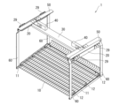
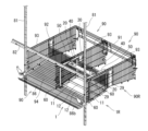
- FIG. 1 is a perspective view of a cage with a mass scale that is an embodiment of the present invention.
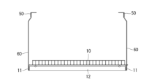
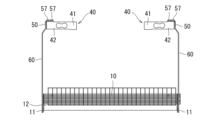
- FIG. 2 is a plan view of the cage with mass scale of FIG. 1; It is a sectional view taken along the line AA.
- FIG. 3 is an end view taken along the line BB. It is a sectional view taken along the line CC.
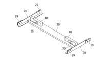
- FIG. 2 is a perspective view showing movable parts of the cage with mass scale of FIG. 1;
- FIG. 7 is a front view of FIG. 6;
- FIG. 2 is a perspective view showing a fixing plate, a base plate, and a load cell in the cage with a mass scale of FIG. 1.
- FIG. FIG. 9 is a front view of FIG. 8;
- FIG. 9 is a front view of FIG. 8; FIG.
- FIG. 2 is a partial perspective view of a structure in which a gauge row to which the cage with a mass scale of FIG. 1 is applied and a conventional cage row are adjacent to each other.
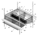
- 11 is a perspective view of the structure of FIG. 10 viewed from the opposite side;
- FIG. It is a perspective view which shows the fixed plate, base plate, and load cell in the cage with a mass scale of a modification.
- a poultry farming facility is equipped with a cage row layer in which cage rows in which a plurality of cages for rearing birds are arranged horizontally and stacked in multiple stages.
- a long feeding trough is placed horizontally along each row of cages.
- FIG. 10 and 11 illustrate both the conventional cage row 90R and the cage row 1R including the cage 1 with a mass scale, so these figures will be partially referred to here.
- the front part 91 of the cage row 1R, the planar structure of the separation floor part 10, and the trough 85 are omitted, and the rear part 92, the floor part 94, the trough 85, and the egg tray 86 of the cage row 90R are omitted.
- the vertical members 81 and the horizontal members 82 are omitted.
- FIG. 11 the planar structures of the floor section 94 and separation floor section 10 of the cage row 1R are omitted.
- the conventional cage row layer 90R includes a plurality of planar structures formed of a plurality of spaced wires or bars, and respective longitudinal members 81 and cross members 82 forming frames that support the planar structures. It has multiple and.
- the planar structure may have a structure in which wires or bars intersect in a lattice pattern, or a structure in which wires or bars are arranged parallel to each other in only one direction and spaced apart from each other.
- the side on which the trough 85 is arranged will be referred to as the "front”, and the opposite side will be referred to as the "rear".
- a front part 91 that covers each cage 90 from the front, a back part 92 that covers it from the rear, a floor part 94 that covers it from below, and a side part 93 that partitions adjacent cages are each made of a planar structure. .
- the front part 91, the back part 92, and the floor part 94 all have the same size as all the cages 90 belonging to one cage row 90R, or the size of the cages 90 belonging to one cage row 90R. It has at least a plurality of sizes. That is, taking the floor section 94 as an example, there is only one floor section 94 for a plurality of cages 90.
- the floor portion 94 is sloped downward toward the front. This is because the eggs laid by the birds in the cage 90 are rolled forward on the floor part 94 by their own weight and are received by the egg tray 86 formed at the front end of the floor part 94.
- two rows of cages 90R are arranged adjacent to each other with their respective backs 92 facing each other.
- one side surface portion 93 is provided so as to span two cages 90 belonging to two adjacent cage rows 90R.
- the front part 91, the back part 92, the floor part 94, and the side part 93 are fixed to at least one of the vertical members 81 and the horizontal members 82 forming the frame.
- the cage row 90R may be configured to further include a top surface portion that covers the cages from above.
- the cage row 1R corresponds to the above-described conventional cage row 90R in which at least one of the cages 90 belonging thereto is replaced with a cage 1 with a mass scale.
- the cage 1 with a mass scale includes a pair of side parts 93, a front part 91, a back part 92, a separation floor part 10, a pair of fixed bars 20, a base plate 30, a load cell 40, a hanging bar 60, and a movable bar 50. ing.
- the side surface portion 93, the front surface portion 91, and the back surface portion 92 have the same configuration as described above regarding the general cage row 90R.
- the cage 1 with a mass scale shares a front part 91 and a back part 92 with another adjacent cage belonging to the same cage row 1R (here, the conventional cage 90).
- the cage row 1R to which the mass scale-equipped cage 1 belongs is adjacent to another cage row (here, the conventional cage row 90R) with their respective back surfaces 92 facing each other.
- the cage 1 with a mass scale shares a side surface 93 with a cage 90 belonging to another cage row 90R.
- the separation floor section 10 has a structure in which a planar structure formed of a plurality of wires or bars is supported from below by a floor support frame 10f.
- the structure of the planar structure is the same as above.
- the floor support frame 10f is formed by assembling a pair of first bars 11 extending in the front-rear direction and a plurality of second bars 12 extending in a horizontal direction perpendicular to the front-rear direction.
- the separation floor portion 10 is separated from the floor surface portions 94 of other adjacent cages 90 that belong to the same cage row layer 1R.
- the separation bed section 10 has an area smaller than the area surrounded by the pair of side sections 93, the front section 91, and the back section 92, and does not come into contact with any of the pair of side sections 93, the front section 91, and the back section 92. I haven't.
- the separating floor 10 does not touch either the longitudinal members 81 or the cross members 82 forming the frame.
- the separation floor part 10 does not contact the components of other adjacent cages 90 that belong to the same cage row 1R.
- the separation floor section 10 is sloped downward toward the front. This is to cause the egg to roll forward due to its own weight, as described above.
- the egg tray 86 described above was formed continuously at the front end of the floor section 94, whereas the egg tray 8b for the cage 1 with a mass scale is separated from the separation floor section 10.
- the egg tray 86b is supported by the floor portion 94 by being formed continuously with the egg tray 86.
- the fixing bar 20 is an elongated member having an L-shaped cross section, and one of the two surfaces forming the L-shape is in contact with the upper end of the side surface portion 93.
- a fixing piece 29 is used here. By sandwiching the side surface portion 93 between the fixed bar 20 and the fixed piece 29, and in this state, the fixed bar 20 and the fixed piece 29 are fastened via the side surface portion 93 with bolts and nuts (not shown). , the fixing bar 20 is fixed to the side part 93.
- the base plate 30 has an elongated flat plate shape and is spanned between a pair of fixed bars 20. Specifically, in each fixing bar 20, the base plate 30 is fixed to the fixing bar 20 with the end of the base plate 30 placed on the other of the two surfaces forming the L-shape. There is. In the fixed bar 20, the position where the base plate 30 is placed is the center in the longitudinal direction.
- the load cells 40 are beam-shaped with an approximately rectangular parallelepiped outer shape, and there are a pair of them. One of the pair of load cells 40 is symmetrically attached near one of both ends of the base plate 30, and the other load cell 40 is symmetrically attached to the other of both ends of the base plate 30.
- the load cell 40 is oriented such that its longitudinal direction coincides with the longitudinal direction of the base plate 30. In other words, the longitudinal direction of the load cell 40 is a horizontal direction orthogonal to the front-rear direction.
- One end of the load cell 40 in the longitudinal direction is a fixing portion 41, and the remaining portion is a load receiving portion 42 made of a strain body.
- a strain gauge (not shown) is attached to the flexure element.
- the load cell 40 is attached to the base plate 30 with the fixing part 41 in contact with the upper surface of the base plate 30 with the load receiving part 42 close to the side surface part 93, and with the fastener 37 penetrated through the base plate 30 from below. There is.
- a gap is formed between the load receiving portion 42 and the upper surface of the base plate 30.
- a hole 35 is provided in a portion of the base plate 30 directly below the load receiving part 42.
- the hanging bar 60 is erected upward from the front end and the rear end of each of the pair of first bars 11.
- the movable bar 50 is an elongated member with an inverted L-shaped cross section, and its longitudinal direction is the front-rear direction. It is fixed to the load cell 40 by a fastener 57 while being in contact with the upper surface of the portion 42 . The position of the movable bar 50 in contact with the load cell 40 is the center in the longitudinal direction.
- a hanging bar 60 is connected from below to the front and rear ends of each of the pair of movable bars 50. Specifically, each movable bar 50 is suspended from the movable bar 50 with the front end and rear end of the other of the two surfaces constituting the L-shape overlapped with the hanging bar 60. A bar 60 is connected.
- the movable bar 50 and the hanging bar 60 are not in contact with any of the pair of side surfaces 93, front surface 91, back surface 92, vertical members 81, and horizontal members 82. Furthermore, none of the separation floor section 10, movable bar 50, and hanging bar 60 in the cage 1 with a mass scale is in contact with the components of other adjacent cages 90 belonging to the same cage row 1R. .
- the weight of the birds is applied to the separation floor part 10.
- the separation floor section 10 is suspended from the movable bar 50 via a suspension bar 60. Therefore, the movable bar 50 is pushed down according to the bird's weight.
- the load receiving portion 42 of the load cell 40 is pushed by the movable bar 50 and deflects downward, so that the weight of the bird can be determined based on the amount of distortion.
- the gap between the load receiving part 42 of the load cell 40 and the upper surface of the base plate 30 and the size of the hole 35 provided in the base plate 30 are such that the upper limit mass assumed as the weight of the bird is determined by the separation floor part 10.
- the load receiving portion 42 is set so as not to come into contact with the base plate 30 when the load is applied.
- the separation floor part 10, the movable bar 50, and the hanging bar 60 are not in contact with any of the pair of side parts 93, the front part 91, the back part 92, the vertical members 81, and the horizontal members 82, and are in the same cage. Since there is no contact with the components of other adjacent cages 90 belonging to the row 1R, the weight of the bird kept in the cage 1 with a mass scale can be accurately measured by the load cell 40.
- the weight of the bird is obtained by subtracting the tare (mass when the bird is not placed on the separation bed 10) from the mass measured by the load cell 40, and integrating the result by the number of load cells 40. If there is more than one bird, divide by that number to get the average value.
- a beam-type load cell 40 having a substantially rectangular external shape is used. Since the separation floor section 10 is inclined downward toward the front, if the longitudinal direction of the load cell 40 is in the front-rear direction, the deflection of the load receiving section 42 will affect the inclination of the separation floor section 10. There is a risk of receiving In contrast, in the present embodiment, the longitudinal direction of the load cell 40 is set to the horizontal direction perpendicular to the front-rear direction, so that the deflection of the load receiving part 42 is less affected by the inclination of the separation floor part 10, and the bird can be detected more accurately. Weight can be measured.
- a beam-type load cell 40 is used as illustrated above, other types of load cells can be used as long as they receive a force from above and cause distortion.
- load cells can be measured based on the strain that occurs in the radial direction orthogonal to the direction of force application. .
- the number of load cells is not limited. For example, if the depth (length in the front-rear direction) of the cage 1 with a mass scale is long, as shown in FIG. 12, a plurality of base plates 30 are provided, and the number of load cells 40 is increased in accordance with the number of base plates 30. Additionally, the number of movable bars and hanging bars is also increased accordingly (not shown). By doing this, even if the depth of the cage is long, the weight of the birds on the separating floor can be measured in a well-balanced manner.
- the present invention is provided in a cage for breeding birds.
- the present invention is not limited thereto, and can be applied to facilities where other animals such as dogs and cats are raised, animal hospitals, etc., where animals are raised in cages and their weights need to be monitored and managed.
Landscapes
- Life Sciences & Earth Sciences (AREA)
- Physics & Mathematics (AREA)
- General Physics & Mathematics (AREA)
- Birds (AREA)
- Environmental Sciences (AREA)
- Zoology (AREA)
- Animal Husbandry (AREA)
- Biodiversity & Conservation Biology (AREA)
- Housing For Livestock And Birds (AREA)
Priority Applications (4)
| Application Number | Priority Date | Filing Date | Title |
|---|---|---|---|
| JP2024510842A JPWO2023188056A1 (https=) | 2022-03-30 | 2022-03-30 | |
| CN202280094075.3A CN118946262A (zh) | 2022-03-30 | 2022-03-30 | 笼子及笼子列结构 |
| PCT/JP2022/015766 WO2023188056A1 (ja) | 2022-03-30 | 2022-03-30 | ケージ及びケージ列構造 |
| KR1020247026538A KR20240165331A (ko) | 2022-03-30 | 2022-03-30 | 케이지 및 케이지열 구조 |
Applications Claiming Priority (1)
| Application Number | Priority Date | Filing Date | Title |
|---|---|---|---|
| PCT/JP2022/015766 WO2023188056A1 (ja) | 2022-03-30 | 2022-03-30 | ケージ及びケージ列構造 |
Publications (1)
| Publication Number | Publication Date |
|---|---|
| WO2023188056A1 true WO2023188056A1 (ja) | 2023-10-05 |
Family
ID=88200221
Family Applications (1)
| Application Number | Title | Priority Date | Filing Date |
|---|---|---|---|
| PCT/JP2022/015766 Ceased WO2023188056A1 (ja) | 2022-03-30 | 2022-03-30 | ケージ及びケージ列構造 |
Country Status (4)
| Country | Link |
|---|---|
| JP (1) | JPWO2023188056A1 (https=) |
| KR (1) | KR20240165331A (https=) |
| CN (1) | CN118946262A (https=) |
| WO (1) | WO2023188056A1 (https=) |
Citations (8)
| Publication number | Priority date | Publication date | Assignee | Title |
|---|---|---|---|---|
| JPS5973735A (ja) * | 1982-10-19 | 1984-04-26 | Nakajima Seisakusho:Kk | ケ−ジ内における鶏の体重測定方法 |
| JPS5991824A (ja) * | 1982-11-17 | 1984-05-26 | 東北大学長 | 荷重計付き動物飼育装置 |
| JPH04135432A (ja) * | 1990-09-26 | 1992-05-08 | Yoshida Erushisu Kk | 養鶏ケージ |
| JPH06209670A (ja) * | 1993-01-12 | 1994-08-02 | Minoru Hosoya | 養鶏装置 |
| JPH11337389A (ja) * | 1998-05-29 | 1999-12-10 | Tsumura & Co | 実験用小動物の体重及び摂餌量の自動測定装置 |
| JP2000097785A (ja) * | 1998-09-22 | 2000-04-07 | A & D Co Ltd | ビーム型ロードセル及びビーム型ロードセル用起歪体 |
| WO2007129672A1 (ja) * | 2006-05-02 | 2007-11-15 | Hytem, Co., Ltd. | 種鶏用ケージ |
| JP2009168505A (ja) * | 2008-01-11 | 2009-07-30 | A & D Co Ltd | ロードセル |
Family Cites Families (4)
| Publication number | Priority date | Publication date | Assignee | Title |
|---|---|---|---|---|
| JPS5542158U (https=) * | 1978-09-14 | 1980-03-18 | ||
| JPS58161804A (ja) * | 1982-03-19 | 1983-09-26 | Tokyo Electric Co Ltd | 歪センサ |
| JPH02310437A (ja) * | 1989-05-25 | 1990-12-26 | Tokyo Electric Co Ltd | ロードセル |
| JPH0755596A (ja) * | 1993-08-17 | 1995-03-03 | Tec Corp | ロードセル |
-
2022
- 2022-03-30 JP JP2024510842A patent/JPWO2023188056A1/ja active Pending
- 2022-03-30 KR KR1020247026538A patent/KR20240165331A/ko active Pending
- 2022-03-30 WO PCT/JP2022/015766 patent/WO2023188056A1/ja not_active Ceased
- 2022-03-30 CN CN202280094075.3A patent/CN118946262A/zh active Pending
Patent Citations (8)
| Publication number | Priority date | Publication date | Assignee | Title |
|---|---|---|---|---|
| JPS5973735A (ja) * | 1982-10-19 | 1984-04-26 | Nakajima Seisakusho:Kk | ケ−ジ内における鶏の体重測定方法 |
| JPS5991824A (ja) * | 1982-11-17 | 1984-05-26 | 東北大学長 | 荷重計付き動物飼育装置 |
| JPH04135432A (ja) * | 1990-09-26 | 1992-05-08 | Yoshida Erushisu Kk | 養鶏ケージ |
| JPH06209670A (ja) * | 1993-01-12 | 1994-08-02 | Minoru Hosoya | 養鶏装置 |
| JPH11337389A (ja) * | 1998-05-29 | 1999-12-10 | Tsumura & Co | 実験用小動物の体重及び摂餌量の自動測定装置 |
| JP2000097785A (ja) * | 1998-09-22 | 2000-04-07 | A & D Co Ltd | ビーム型ロードセル及びビーム型ロードセル用起歪体 |
| WO2007129672A1 (ja) * | 2006-05-02 | 2007-11-15 | Hytem, Co., Ltd. | 種鶏用ケージ |
| JP2009168505A (ja) * | 2008-01-11 | 2009-07-30 | A & D Co Ltd | ロードセル |
Also Published As
| Publication number | Publication date |
|---|---|
| KR20240165331A (ko) | 2024-11-22 |
| JPWO2023188056A1 (https=) | 2023-10-05 |
| CN118946262A (zh) | 2024-11-12 |
Similar Documents
| Publication | Publication Date | Title |
|---|---|---|
| US9668406B2 (en) | Sectional yield measurement on row independent harvesting head | |
| Ishii et al. | Combined effects of inflorescence architecture, display size, plant density and empty flowers on bumble bee behaviour: experimental study with artificial inflorescences | |
| RU2769467C2 (ru) | Взвешивающий модуль для гнезда в птицеводческом хозяйстве и гнездо | |
| CN107509657A (zh) | 一种种猪性能测定站及测定系统 | |
| CN104686390A (zh) | 一种蛋鸡栖架分布监测系统 | |
| US4286679A (en) | Animal scale | |
| KR20170058521A (ko) | 가금관리장치 | |
| WO2023188056A1 (ja) | ケージ及びケージ列構造 | |
| NL8801029A (nl) | Werkwijze voor het mesten van pluimvee. | |
| Oksanen et al. | Maternal effort and male quality in the bank vole, Clethrionomys glareolus | |
| CN212589620U (zh) | 对家畜的活动进行检测的活动检测设备 | |
| Turner et al. | An automatic weighing system for poultry | |
| KR101730048B1 (ko) | 양계장의 종계용 직립케이지 구조 | |
| CN207284722U (zh) | 一种种猪性能测定站及测定系统 | |
| JPS59166027A (ja) | 飼育施設内の家畜群の体調を測定する方法および装置 | |
| WO2019007521A1 (en) | METHOD FOR EGG OUTBREAK | |
| JP2003114145A (ja) | 家畜等の体重測定器および体重計測施設並びに自動体重計測装置 | |
| WO2013132078A1 (en) | A weighing platform and a weighing system for dynamically weighing a flow of items | |
| CN115697049A (zh) | 雏鸡的生产方法和雏鸡的生产系统 | |
| CN202778982U (zh) | 一种养鸽场种鸽筛选装置 | |
| US3478721A (en) | Brooding and growing cage | |
| US20180132445A1 (en) | Cattle stall system | |
| Daikwo et al. | Inheritance of egg quality traits in the Japanese quail | |
| CN115191371A (zh) | 一种鸡的料肉比检测装置及其方法 | |
| Murray Jr et al. | The evolution of clutch size. I. An equation for predicting clutch size |
Legal Events
| Date | Code | Title | Description |
|---|---|---|---|
| 121 | Ep: the epo has been informed by wipo that ep was designated in this application |
Ref document number: 22935204 Country of ref document: EP Kind code of ref document: A1 |
|
| ENP | Entry into the national phase |
Ref document number: 2024510842 Country of ref document: JP Kind code of ref document: A |
|
| WWE | Wipo information: entry into national phase |
Ref document number: 202427063360 Country of ref document: IN |
|
| WWE | Wipo information: entry into national phase |
Ref document number: 202280094075.3 Country of ref document: CN |
|
| NENP | Non-entry into the national phase |
Ref country code: DE |
|
| 32PN | Ep: public notification in the ep bulletin as address of the adressee cannot be established |
Free format text: NOTING OF LOSS OF RIGHTS PURSUANT TO RULE 112(1) EPC (EPO FORM 1205 DATED 21.02.25) |
|
| 122 | Ep: pct application non-entry in european phase |
Ref document number: 22935204 Country of ref document: EP Kind code of ref document: A1 |