WO2023188026A1 - 磁気結合インダクタおよび、その組立方法 - Google Patents
磁気結合インダクタおよび、その組立方法 Download PDFInfo
- Publication number
- WO2023188026A1 WO2023188026A1 PCT/JP2022/015627 JP2022015627W WO2023188026A1 WO 2023188026 A1 WO2023188026 A1 WO 2023188026A1 JP 2022015627 W JP2022015627 W JP 2022015627W WO 2023188026 A1 WO2023188026 A1 WO 2023188026A1
- Authority
- WO
- WIPO (PCT)
- Prior art keywords
- core
- magnetic core
- spacer member
- magnetically coupled
- winding shaft
- Prior art date
- Legal status (The legal status is an assumption and is not a legal conclusion. Google has not performed a legal analysis and makes no representation as to the accuracy of the status listed.)
- Ceased
Links
Images





Classifications
-
- H—ELECTRICITY
- H01—ELECTRIC ELEMENTS
- H01F—MAGNETS; INDUCTANCES; TRANSFORMERS; SELECTION OF MATERIALS FOR THEIR MAGNETIC PROPERTIES
- H01F5/00—Coils
- H01F5/02—Coils wound on non-magnetic supports, e.g. formers
-
- H—ELECTRICITY
- H01—ELECTRIC ELEMENTS
- H01F—MAGNETS; INDUCTANCES; TRANSFORMERS; SELECTION OF MATERIALS FOR THEIR MAGNETIC PROPERTIES
- H01F17/00—Fixed inductances of the signal type
- H01F17/04—Fixed inductances of the signal type with magnetic core
-
- H—ELECTRICITY
- H01—ELECTRIC ELEMENTS
- H01F—MAGNETS; INDUCTANCES; TRANSFORMERS; SELECTION OF MATERIALS FOR THEIR MAGNETIC PROPERTIES
- H01F27/00—Details of transformers or inductances, in general
- H01F27/24—Magnetic cores
- H01F27/26—Fastening parts of the core together; Fastening or mounting the core on casing or support
- H01F27/263—Fastening parts of the core together
-
- H—ELECTRICITY
- H01—ELECTRIC ELEMENTS
- H01F—MAGNETS; INDUCTANCES; TRANSFORMERS; SELECTION OF MATERIALS FOR THEIR MAGNETIC PROPERTIES
- H01F27/00—Details of transformers or inductances, in general
- H01F27/28—Coils; Windings; Conductive connections
- H01F27/30—Fastening or clamping coils, windings, or parts thereof together; Fastening or mounting coils or windings on core, casing, or other support
-
- H—ELECTRICITY
- H01—ELECTRIC ELEMENTS
- H01F—MAGNETS; INDUCTANCES; TRANSFORMERS; SELECTION OF MATERIALS FOR THEIR MAGNETIC PROPERTIES
- H01F27/00—Details of transformers or inductances, in general
- H01F27/28—Coils; Windings; Conductive connections
- H01F27/30—Fastening or clamping coils, windings, or parts thereof together; Fastening or mounting coils or windings on core, casing, or other support
- H01F27/306—Fastening or mounting coils or windings on core, casing or other support
-
- H—ELECTRICITY
- H01—ELECTRIC ELEMENTS
- H01F—MAGNETS; INDUCTANCES; TRANSFORMERS; SELECTION OF MATERIALS FOR THEIR MAGNETIC PROPERTIES
- H01F27/00—Details of transformers or inductances, in general
- H01F27/28—Coils; Windings; Conductive connections
- H01F27/32—Insulating of coils, windings, or parts thereof
-
- H—ELECTRICITY
- H01—ELECTRIC ELEMENTS
- H01F—MAGNETS; INDUCTANCES; TRANSFORMERS; SELECTION OF MATERIALS FOR THEIR MAGNETIC PROPERTIES
- H01F27/00—Details of transformers or inductances, in general
- H01F27/34—Special means for preventing or reducing unwanted electric or magnetic effects, e.g. no-load losses, reactive currents, harmonics, oscillations, leakage fields
- H01F27/346—Preventing or reducing leakage fields
-
- H—ELECTRICITY
- H01—ELECTRIC ELEMENTS
- H01F—MAGNETS; INDUCTANCES; TRANSFORMERS; SELECTION OF MATERIALS FOR THEIR MAGNETIC PROPERTIES
- H01F3/00—Cores, Yokes, or armatures
- H01F3/10—Composite arrangements of magnetic circuits
-
- H—ELECTRICITY
- H01—ELECTRIC ELEMENTS
- H01F—MAGNETS; INDUCTANCES; TRANSFORMERS; SELECTION OF MATERIALS FOR THEIR MAGNETIC PROPERTIES
- H01F3/00—Cores, Yokes, or armatures
- H01F3/10—Composite arrangements of magnetic circuits
- H01F3/14—Constrictions; Gaps, e.g. air-gaps
-
- H—ELECTRICITY
- H01—ELECTRIC ELEMENTS
- H01F—MAGNETS; INDUCTANCES; TRANSFORMERS; SELECTION OF MATERIALS FOR THEIR MAGNETIC PROPERTIES
- H01F37/00—Fixed inductances not covered by group H01F17/00
-
- H—ELECTRICITY
- H01—ELECTRIC ELEMENTS
- H01F—MAGNETS; INDUCTANCES; TRANSFORMERS; SELECTION OF MATERIALS FOR THEIR MAGNETIC PROPERTIES
- H01F38/00—Adaptations of transformers or inductances for specific applications or functions
- H01F38/08—High-leakage transformers or inductances
-
- H—ELECTRICITY
- H01—ELECTRIC ELEMENTS
- H01F—MAGNETS; INDUCTANCES; TRANSFORMERS; SELECTION OF MATERIALS FOR THEIR MAGNETIC PROPERTIES
- H01F38/00—Adaptations of transformers or inductances for specific applications or functions
- H01F38/08—High-leakage transformers or inductances
- H01F38/10—Ballasts, e.g. for discharge lamps
-
- H—ELECTRICITY
- H01—ELECTRIC ELEMENTS
- H01F—MAGNETS; INDUCTANCES; TRANSFORMERS; SELECTION OF MATERIALS FOR THEIR MAGNETIC PROPERTIES
- H01F38/00—Adaptations of transformers or inductances for specific applications or functions
- H01F38/14—Inductive couplings
-
- H—ELECTRICITY
- H01—ELECTRIC ELEMENTS
- H01F—MAGNETS; INDUCTANCES; TRANSFORMERS; SELECTION OF MATERIALS FOR THEIR MAGNETIC PROPERTIES
- H01F41/00—Apparatus or processes specially adapted for manufacturing or assembling magnets, inductances or transformers; Apparatus or processes specially adapted for manufacturing materials characterised by their magnetic properties
- H01F41/02—Apparatus or processes specially adapted for manufacturing or assembling magnets, inductances or transformers; Apparatus or processes specially adapted for manufacturing materials characterised by their magnetic properties for manufacturing cores, coils, or magnets
- H01F41/04—Apparatus or processes specially adapted for manufacturing or assembling magnets, inductances or transformers; Apparatus or processes specially adapted for manufacturing materials characterised by their magnetic properties for manufacturing cores, coils, or magnets for manufacturing coils
- H01F41/06—Coil winding
- H01F41/098—Mandrels; Formers
Definitions
- the present invention relates to a magnetically coupled inductor installed in electronic circuits of various devices, and a method for assembling the same.
- the two built-in inductors are operated in an interleaved manner to reduce ripples and improve DC superimposition characteristics by canceling out the DC magnetic flux generated in the core.As a result, the size of the coupled inductor can be reduced. It is said that it is possible to reduce the size of the capacitor, increase efficiency, and further reduce the size of the capacitor.
- a conventional magnetically coupled inductor as shown in Patent Document 1 below (particularly, FIG. 1), a ring-shaped third core 102 is inserted through the middle legs of the first core 101 and the second core 101'. It is known that the bobbin is sandwiched between the flanges 112 and 112' of the bobbin 110 and 110' which are divided into two. Note that each of the divided bobbins 110 and 110' is provided with a winding shaft portion 111 and 111' around which a coil winding is wound.
- the third core 102 is sandwiched between the two divided bobbins 110 and 110', the third core 102 is attached to the substrate by protruding from the bottom of each bobbin 110 and 110'. It was difficult to ensure the dimensional accuracy of the interval between the two terminal rows 115, 115' and the rigidity of the bobbins 110, 110'. Further, since the shape (for example, thickness) of the third core 102 is limited to a predetermined shape, it is difficult to adjust the leakage inductance value according to the situation.
- the present invention was made in view of the above circumstances, and it is possible to easily adjust the leakage inductance value according to the situation in a magnetically coupled inductor in which two built-in inductors are operated in an interleaved manner. It is an object of the present invention to provide a magnetically coupled inductor that can easily ensure the dimensional accuracy of the terminal pin spacing between terminal blocks and the rigidity of the winding shaft portion of the bobbin, and a method for assembling the same.
- the magnetically coupled inductor of the present invention is Each has a middle leg, outer legs located on both sides of the middle leg, and a back surface connecting the middle leg and the outer leg, and the tips of the middle legs are connected to each other and correspond to each other.
- a first magnetic core and a second magnetic core arranged such that the tips of the outer leg portions abut each other; a bobbin through which the middle leg portions of the first magnetic core and the second magnetic core are inserted and disposed outside the middle leg portions of these two magnetic cores;
- an annular spacer member consisting of a flange; An axial region of the winding shaft is divided by the spacer member, and a first coil winding is wound around one region of the winding shaft, and a second coil is wound around the other region. comprising a winding;
- the shape of the third magnetic core and the third magnetic core are adjusted so that a desired leakage inductance value is generated depending on the positional relationship with the first magnetic core and the second magnetic core.
- At least one of the material characteristic elements of the magnetic core described in item 3 is set to a predetermined size and is attached to the outer periphery of the cylindrical portion of the spacer member in a circumferential direction. It is characterized by:
- the at least one factor is the thickness of the third magnetic core.
- the width of the cylindrical portion of the spacer member is adjusted to a size corresponding to the thickness of the third magnetic core.
- the at least one element is an inner diameter of the third magnetic core.
- the outer diameter of the cylindrical portion of the spacer member is adjusted to a size corresponding to the inner diameter of the third magnetic core.
- the at least one element is an outer diameter of the third magnetic core.
- the at least one factor is a magnetic saturation property of the material of the third magnetic core.
- the attachment of the spacer member to the winding shaft section includes a plurality of first engaging parts arranged in a circumferential direction on an outer peripheral surface of the winding shaft part, and a plurality of first engaging parts arranged on an inner peripheral surface of the cylindrical part. It is preferable that this is done by mutually engaging second engaging parts arranged in the circumferential direction so as to correspond to the first engaging part.
- each of the spacer members divided in the circumferential direction includes a spacer assembly engaging portion that engages with and integrates with each other while attached to the winding shaft portion.
- the outermost periphery of the flanges disposed at both ends of the winding shaft portion of the bobbin is set at a height close to the outermost periphery of the flanges disposed at both ends of the cylindrical portion of the spacer member. It is preferable that it be configured.
- the method for assembling a magnetically coupled inductor of the present invention includes: A first magnetic core and a second magnetic core each having a middle leg, an outer leg located on both sides of the middle leg, and a back surface connecting the middle leg and the outer leg. abutting the tips of the middle leg portions and the corresponding tips of the outer leg portions against each other, inserting the middle leg portions of the first magnetic core and the second magnetic core into a hollow part of the bobbin;
- the bobbin is composed of a cylindrical part on which a third annular magnetic core is mounted in the circumferential direction of the winding shaft part through which the middle leg part of the bobbin is inserted, and collar parts arranged at both ends of the cylindrical part.
- the leakage inductance value of the third magnetic core is set to a desired value.
- the annular third magnetic core can be formed into a desired shape by selecting at least one of the shape of the third magnetic core and the material properties of the third magnetic core. It is configured such that it can be placed on a spacer member attached to the winding shaft of the bobbin in a state where the leakage inductance value is adjusted to be . This makes it easy to adjust the leakage inductance value of the magnetically coupled inductor, and since the length and rigidity of the bobbin shaft do not change during adjustment, the dimensional accuracy of the terminal pin spacing between terminal blocks It is easy to ensure the rigidity of the winding shaft of the bobbin.
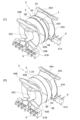
- FIG. 1 is a perspective view showing a magnetically coupled inductor according to an embodiment of the present invention ((A) is a state in which a bobbin and a spacer member are removed, and (B) is a state in which a bobbin, a spacer member, and a coil winding are removed).
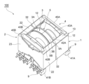
- FIG. 1 is a perspective view showing a magnetically coupled inductor (with a coil winding removed) according to an embodiment of the present invention.
- 1 is a schematic cross-sectional view showing the flow of magnetic flux in a magnetically coupled inductor according to an embodiment of the present invention.
- a mode for adjusting the leakage inductance value ((A) is a mode for changing the thickness of the spacer member and the ring core, and (B) is a mode for adjusting the outer diameter of the central groove of the spacer member.
- (C) is a schematic diagram showing a mode in which the inner diameter of the ring core is changed, (C) is a mode in which the outer diameter of the ring core is changed, and (D) is a mode in which the magnetic saturation characteristic of the ring core is changed.
- FIG. 2 is a perspective view showing assembly process 1 ((A), (B)) of a magnetically coupled inductor according to an embodiment of the present invention.
- FIG. 2 is a perspective view showing a spacer member of a magnetically coupled inductor according to an embodiment of the present invention ((A) is a state in which the spacer member is integrated, and (B) is a state in which the spacer member is disassembled into two).
- FIG. 2 is a schematic diagram for explaining a conventional technique.
- FIG. 1(A) is a perspective view of the magnetically coupled inductor 100 according to the present embodiment with the bobbin and spacer member removed
- FIG. 1(B) is the bobbin and spacer member of the magnetically coupled inductor 100 according to the present embodiment.
- FIG. 2 is a perspective view of the magnetically coupled inductor 100 according to the present embodiment with the coil winding removed.
- the magnetically coupled inductor 100 of this embodiment includes a first core 1 and a second core 2 each made of a PQ core, and a ring core (annular core) as main elements.
- the third core 3 (3A, 3B), a first coil winding 6A, and a second coil winding 6B are provided.
- the first core 1 and the second core 2 are made of, for example, a ferrite core, and each has a cylindrical middle leg part 11, 21, an outer leg part 12 arranged on both sides of the middle leg part 11, 21, 12, 22, 22, and back parts 13, 23 that connect these middle legs 11, 21 and outer legs 12, 12, 22, 22, and these first core 1 and second core 2 have They are arranged opposite to each other so as to have a symmetrical shape.
- the length of the middle legs 11, 21 is approximately 1/2 of the distance between the opposing back surfaces 13, 23, and the outer legs 12, 12, 22, 22 have an arcuate inner surface and a flat outer surface. It has a plate shape. Further, the corresponding tips of the three leg parts 11, 12, 12 constituting the first core 1 and the three leg parts 21, 22, 22 constituting the second core 2 have gaps 31, 32 at minute intervals. , 32 so as to face each other.
- the third core 3 is made of, for example, a ferrite core, and has an annular shape with a rectangular cross section. Further, the third core 3 is formed by combining a pair of semicircular ring core members (semicircular ring cores) 3A and 3B.
- FIG. 2 shows a state in which the bobbin 4 and spacer member 5, which are not shown in FIG. 1(B), are combined with the first core 1, second core 2, and third core 3.
- the bobbin 4 is made of insulating resin, and, as shown in FIG. 5A, has flanges 43A and 43B at both ends of a cylindrical winding shaft 42, and a terminal block 41A below each of the flanges 43A and B. , B.
- Each terminal block 41A, B is provided with a plurality of terminal pins 9, 9, respectively.
- the middle leg part 11 of the first core 1 is inserted into the cylindrical winding shaft part 42 of the bobbin 4 from one end side of the hollow part 42C, and the middle leg part 21 of the second core 2 is inserted from the other end side.
- the bobbin 4 is disposed on the outside of each of the middle legs 11 and 21.
- the corresponding middle leg parts 11 and 21 and the outer leg parts 12, 12, 22, and 22 on both sides are butted against each other, and the corresponding leg parts are abutted against each other. Gaps 31, 32, 32 are provided between each (see FIG. 1(B)).
- a plurality of engagements are placed at approximately the center in the axial direction of the outer circumferential surface of the winding shaft portion 42 of the bobbin 4.
- a mating protrusion 44a is provided, and the spacer member 5 is attached to this position.
- This spacer member 5 has a ring core mounting groove 5C in which the third core 3 is mounted between both spacer flanges 5A and 5B. It has an inner diameter that allows it to be fitted along the outer circumferential surface.
- the ring core mounting groove 5C is provided with the same number of engagement holes 5Ca that engage with the engagement protrusions 44a installed on the outer peripheral surface of the winding shaft 42 as the number of engagement protrusions 44a installed (Fig. 9(A), (B)).
- this cylindrical spacer member 5 in order to be able to attach this cylindrical spacer member 5 to the winding shaft part 42, as shown in FIG. 5Ca is engaged with the corresponding engagement protrusion 44a and these two semicircular ring parts 51, 52 are attached to the winding shaft part 42, these two semicircular ring parts 51, 52 engage with each other. They are designed to be integrated together. The structure that contributes to the engagement of these two semicircular portions 51 and 52 will be described later.
- each engagement protrusion 44a is provided at a substantially central position in the axial direction of the outer circumferential surface of the winding shaft portion 42, and each engagement hole 5Ca is also provided in the axial direction of the ring core mounting groove 5C. Since the spacer member 5 is provided at a substantially central position, when the spacer member 5 is attached to the winding shaft portion 42, the winding shaft regions 42A and B of the winding shaft portion 42 are approximately the same on both sides of the spacer member 5 in the axial direction. It has an area of .
- a first coil winding 6A is wound around one winding shaft region 42A divided by the spacer member 5, and a second coil winding 6B is wound around the other winding shaft region 42B. Both ends of the first coil winding 6A are connected to corresponding terminal pins 9 on the terminal block 41A side, and both ends of the second coil winding 6B are connected to corresponding terminal pins 9 on the terminal block 41B side. Ru.
- the semicircular ring cores 3A and 3B which are divided into two semicircular rings, are attached to the ring core mounting groove 5C of the spacer member 5.
- a third core is arranged along the entire outer peripheral surface of 5C. Note that while the semicircular ring cores 3A, B are attached to the outer circumferential surface of the ring core mounting groove 5C, the outer circumferential surfaces of the semicircular ring cores 3A, B are Wrap the ring core with fixing tape 71 (see FIG. 6(D)).
- the magnetically coupled inductor 100 of this embodiment which has the basic configuration as described above, has a third core 3 made of an annular magnetic core sandwiched between the first core 1 and the second core 2, so that the core part is exposed to sunlight in plan view. It has a 2-in-1 (2-in-1) structure formed in a letter shape.
- the magnetic flux 8 in the magnetically coupled inductor 100 whose core part is formed in a diagonal shape in plan view flows as shown by the arrow in FIG. 3, and flows between the first coil winding 6A and the second coil winding 6B.
- the magnetic fluxes 8 passing through the third core 3 generated by the passing currents are in the same direction.
- the first core 1 and the second core 2 have gaps 31, 32, 32 between the middle legs 11, 21 and the outer legs 12, 12, 22, 22, respectively. are formed and separated. Therefore, in the first core 1, the magnetic fluxes 8 passing through the back surface 13 from the outer legs 12, 12 on both sides merge at the middle leg 11, and both flow toward the distal end surface of the middle leg 11. On the other hand, in the second core 2, the magnetic fluxes passing through the back surface 23 from the outer legs 22, 22 on both sides merge at the middle leg 21, and both flow toward the distal end surface of the middle leg 21.
- the magnetic flux 8 branched in the direction of the third core 3 before the collision passes through the third core 3 and reaches the outer legs 12, 12, 22, 22 of the first core 1 and the second core 2. reach.
- a magnetic loop consisting of the magnetic flux 8 circulating in the direction of the arrow as shown in FIG. 3 is formed in the first core 1, the second core 2, and the third core 3.
- a gap 33 at a predetermined interval is also formed between the third core 3 and the outer leg portions 12, 12, 22, 22 of the first core 1 and the second core 2.
- the core portions (the first core 1, the second core 2, and the third core 3) are formed as a whole in a Japanese character shape in plan view, and the middle legs of the first core 1 and the second core 2 are Of the magnetic flux 8 flowing through the first core 11 and 21, the proportion of the magnetic flux 8 that is branched in the third core 3 direction and flows to the outer leg portions 12, 12, 22, 22 of the first core 1 and the second core 2 is This can be adjusted by changing the degree of ease with which the magnetic flux 8 flows from the middle legs 11 and 21 of the first and second cores 2 to the third core 3.
- the ease with which the magnetic flux 8 flows from the middle legs 11 and 21 in the direction of the third core 3 is determined by focusing on the above-mentioned points. At least one element is replaced ( The structure is such that the leakage inductance (leakage flux) value can be adjusted to a desired value by selecting the desired leakage inductance (leakage flux).
- the structure is such that the leakage inductance (leakage flux) value can be adjusted to a desired value by selecting the desired leakage inductance (leakage flux).
- the thickness of the third core 3 (ring core) it is desirable to change the width of the ring core mounting groove 5C of the spacer member 5 accordingly.
- the inner diameter of the third core 3 (ring core) it is desirable to change the outer diameter of the ring core mounting groove 5C of the spacer member 5 accordingly.
- a plurality of types of third cores 3 with different thicknesses (widths) are prepared, and the one that provides the desired leakage inductance value is placed in the ring core mounting groove 5C. Installing. This is because the greater the thickness (width) of the third core 3, the greater the amount of magnetic flux 8 branched in the direction of the third core 3 shown in FIG. 3, that is, the amount of leakage inductance.
- a plurality of types of third cores 3 having different magnetic saturation characteristics are prepared, and the one that provides the desired leakage inductance value is installed in the ring core mounting groove 5C. .
- the selected third cores 3 can have the same shape, so the spacer member 5 may be the same.
- a plurality of third cores 3 having different leakage inductance values are arranged, and the third core 3 that can obtain a desired leakage inductance value is connected to the winding of the bobbin 4. Since it is mounted on the spacer member 5 attached to the outer circumferential surface of the shaft portion 42, the winding shaft can be adjusted according to the change in the thickness of the third core 3, as in the prior art described above (Patent Document 1). There is no need to change the length of the portion 42 in the axial direction, and the interval between the terminal pins 9 between the terminal blocks 41A and 41B does not need to be changed in accordance with the change in the third core 3. This makes it easy to ensure the accuracy of the interval between the terminal pins 9 between the terminal blocks 41A and 41B and the rigidity of the winding shaft portion 42 of the bobbin 4 when adjusting the leakage inductance value.
- a bobbin 4 as shown in FIG. 5(A) is manufactured.
- the bobbin 4 is made of insulating resin and is manufactured by molding.
- the winding shaft portion 42 around which the coil windings 6A and 6B are wound has a cylindrical shape with a hollow portion 42C, and approximately disk-shaped flanges 43A and B are provided at both ends of the winding shaft portion 42.
- terminal blocks 41A, B are suspended below each collar 43A, B, and tape suspension parts 45A, B suspend an exterior tape 73 (see FIG. 8(G)) above each collar 43A, B.
- Six metal terminal pins 9, 9 are arranged in parallel on each terminal block 41A, 41B so as to face sideways and downwards, respectively.
- This engagement protrusion has a rectangular parallelepiped shape elongated in the circumferential direction, and is shaped to exactly engage with the engagement hole 5Ca of the spacer member 5 (see FIGS. 9A and 9B).
- the spacer member 5 is attached to the outer peripheral surface of the winding shaft portion 42 of the bobbin 4.
- this spacer member 5 is composed of two semicircular ring parts 51 and 52, and the semicircular ring part 51 and the semicircular ring part 52 are respectively connected to the bobbin 4 from above and from below. is brought close to the winding shaft 42 so that each engagement hole 5Ca formed in each semicircular ring part 51, 52 engages with an engaging protrusion 44a installed on the outer peripheral surface of the winding shaft 42.
- each semicircular ring part 51, 52 is attached to the winding shaft part 42.
- the semicircular ring parts 51 and 52 are attached to the winding shaft part 42 and are combined into a ring shape as shown in FIG. 9(A).
- the spacer member 5 combined in an annular shape stably holds the cylindrical ring core mounting groove 5C in which the third core 3 is mounted and the side surface of the third core 3.
- spacer flanges 5A and 5B are provided on both sides of the ring core mounting groove 5C. Therefore, the width of the ring core mounting groove 5C is set to a size corresponding to the thickness (width) of the third core 3 to be mounted.
- the part of the spacer collar part 5A on the semicircular ring part 51 side is the spacer collar part.
- the part 5A1 and the part of the spacer flange 5A on the semicircular ring part 52 side are respectively referred to as the spacer flange part 5A2
- the part of the flange part 5B on the semicircular ring part 51 side are called the flange part 5B1 and the semicircle of the flange part 5B.
- the parts on the ring part 52 side are respectively referred to as flange parts 5B2, and the parts on the semicircular ring part 51 side of the ring core mounting groove 5C are called ring core mounting grooves 5C1, and the semicircular ring part 52 of the ring core mounting groove 5C
- the side portion is called a ring core mounting groove portion 5C2.
- the two semicircular portions 51 and 52 of the spacer member 5 are spacer assembly engaging portions 51A, B, 52A, and B that engage with each other and are integrated when attached to the outer circumferential surface of the bobbin 4. It is equipped with The spacer assembly engaging part 51A and the spacer assembly engaging part 52B have the same shape, and the inner part of both spacer collar parts 5A1 and 5B1 at one end of the semicircular ring part 51 (spacer assembly engaging part 51A), The inner portions of both spacer collars 5A2 and 5B2 at the other end of the semicircular ring portion 52 (spacer assembly engagement portion 52B) are cut out.
- the spacer assembly engaging part 51B and the spacer assembly engaging part 52A have the same shape, and both spacer collar parts 5A1 and 5B1 at the other end of the semicircular ring part 51 (spacer assembly engaging part 51B)
- the outer portion and the outer portion of both spacer collar portions 5A2 and 5B2 at one end portion of the semicircular ring portion 52 (spacer assembly engagement portion 52A) are cut out.
- notched spacer collar portions 5A1, 5B1, 5A2, and 5B2 of the spacer assembly engagement portions 51A and 52B are provided with engagement recesses (see FIG. 9B) extending in the radial direction on the inwardly facing surfaces.
- 51Q and 52Q (51Q is not shown) are formed (only one engagement recess of the spacer assembly engagement portion 52B is shown), and the spacer assembly engagement portions 51B and 52A are
- the notched spacer flanges 5A1, 5B1, 5A2, and 5B2 have engaging convex portions extending radially on the outward facing surface (Fig. 9(B) shows the spacer assembly engaging portions 51B and 52A). Only one engagement convex portion is shown) 51P and 52P are formed.
- the spacer member 5 is made of resin, and has a spacer flange in which engaging recesses 51Q, 52Q (51Q is not shown) and engaging protrusions 51P, 52P are formed in the spacer assembly engaging parts 51A, 51B, 52A, 52B. Since the portions 5A1, 5B1, 5A2, and 5B2 are thin-walled, these portions are easily elastically deformed, and therefore the engaging concave portions 51Q, 52Q (51Q is not shown) and the engaging convex portion 51P are easily elastically deformed. , 52P can be easily engaged.
- half of the third core 3 is placed on the outer circumferential surface of the ring core mounting groove 5C of the spacer member 5 attached to the outer circumferential surface of the winding shaft portion 42 of the bobbin 4 as described above.
- the semicircular ring cores 3A and 3B are fitted into the ring core mounting groove 5C so that the inner peripheral surfaces of the semicircular ring cores 3A and 3B are aligned.
- the outer peripheral surfaces of the semicircular ring cores 3A and B are attached to the ring cores so that the semicircular ring cores 3A and B of the third core 3 are held with respect to the spacer member 5. It is wound with a fixing tape 71.
- first coil windings 6A and second coil windings 6B are arranged in the winding shaft regions 42A and 42B of the winding shaft portion 42, which are divided by the spacer member 5. Roll around.
- the middle leg part 11 of the first core 1 is inserted into the hollow part 42C of the cylindrical winding shaft part 42 of the bobbin 4 from one end side, and the middle leg part 11 of the first core 1 is inserted from the other end side. 2. Insert the middle leg portion 21 of the core 2.
- the first core 1 and the second core 2 are arranged so that the corresponding middle legs 11 and 21 and the outer legs 12, 12, 22, and 22 on both sides butt against each other. Furthermore, the corresponding legs are arranged so that gaps 31, 32, and 32 are provided at predetermined intervals between each of the corresponding legs.
- the bobbin 4 and each of the cores 1 to 3 are fixed as one body by wrapping the core fixing tape 72 around the circumferential surfaces of the side portions of the first core 1 and the second core 2. Note that as a means for physically integrating the bobbin 4 and each of the cores 1 to 3, an adhesive, a fastening metal fitting, or the like may be used instead of the core fixing tape 72.
- the first coil winding 6A and the second coil winding 6B are wound to a position approximately equal to the outer peripheral position of the flanges 5A and B of the spacer member 5. It is configured.
- the outer circumferential position of the coil windings 6A, B is adjusted taking into consideration both the wire diameter and the number of turns of the coil windings 6A, B. It is possible to balance the generated magnetic flux and heat generation (the larger the wire diameter, the more the amount of heat generation can be suppressed). Further, as shown in FIG.
- the outermost peripheries of both flanges 43A and 43B of the bobbin 4 and the outermost peripheries of both flange portions 5A and 5B of the spacer member 5 are close to each other in height. It is set as follows. As a result, the heights of parts protruding upward in the upper open area surrounded by the first core 1 and the second core 2 shown in FIG. 7(F) can be made equal, and the exterior tape shown in FIG. 8(G) The winding operation of 73 can be performed smoothly, and the product can be integrated reliably.
- the step for setting the leakage inductance value to a desired value is to set the third core 3 selected using one of the methods shown in FIGS. 6(C), this is done by mounting and fixing the ring core on the ring core mounting groove 5C of the spacer member 5.
- the thickness (width) of the third core 3 is selected (see Fig. 4(A)), or the inner diameter of the third core 3 is selected (the outer diameter is not changed) (see Fig. 4(A)). 4(B)), select the outer diameter of the third core 3 (without changing the inner diameter) (see FIG. 4(C)), or select the magnetic saturation characteristics of the third core 3 (see FIG. 4(C)). (D)) or by selecting the desired third core 3 and attaching it to the spacer member 5. Note that it is also possible to use a combination of a plurality of these methods.
- a magnetically coupled inductor having a core portion shaped like a Japanese character in plan view is configured, so as shown in FIG.
- a spacer member 5 having a ring core mounting groove 5C having a width corresponding to the thickness of the third core 3 is attached to the winding shaft 42.
- the magnetically coupled inductor and the method of assembling the same according to the present invention are not limited to the above embodiments, and can be modified in various other ways.
- PQ cores are used as the first core 1 and the second core 2, but various types of cores such as an EE core or an EER core may be used instead.
- various types of cores such as EE cores and EER cores can be constructed by combining a plurality of I core members and cylindrical core members.
- the winding direction of the coil windings 6A and 6B and the winding direction of the coil windings 6A and 6B are such that the flow directions (directions of arrows) of the magnetic flux shown in FIG. 3 are all reversed. A similar effect can be obtained by adjusting the direction of the current flowing through B.
- the shape of the bobbin 4 is not limited to that of the above embodiment, and may have other shapes, such as an engaging protrusion installed on the outer peripheral surface of the winding shaft portion 42. An engagement hole is formed in place of 44a, and an engagement protrusion that engages with the engagement hole of this winding shaft is replaced with an engagement hole 5Ca on the inner circumferential surface of the ring core mounting groove 5C of the spacer member 5.
- the coil windings 6A, B are round wires, but the coil windings 6A, B are not limited to this, and other winding wires may be used. For example, winding by edge coil winding of flat wire is not excluded.
- the third core 3 is divided into two parts, but it is also possible to divide it into three or more parts.
- the spacer member 5 is composed of two semicircular parts 51 and 52, but the spacer member 5 can also be composed of three or more partial circular parts. However, it is important to form an engagement part (an engagement hole, an engagement protrusion, etc.) for attachment to the winding shaft part 42 for each partial annular part.
- the spacer assembly engagement parts 51A, 52B are provided with engagement recesses 51Q, 52Q (51Q is not shown), and the spacer assembly engagement parts 51B, 52A are provided with engagement protrusions 51P, 52P.
- the step of selecting the third core 3 and attaching it to the spacer member 5 is performed before the step of winding each coil winding 6A, B around the winding shaft portion 42.
- the order may be changed, or the process of winding the coil windings 6A and 6B may be performed during the process of selecting and installing the third core 3.
Landscapes
- Engineering & Computer Science (AREA)
- Power Engineering (AREA)
- Chemical & Material Sciences (AREA)
- Composite Materials (AREA)
- Manufacturing & Machinery (AREA)
- Microelectronics & Electronic Packaging (AREA)
- Coils Or Transformers For Communication (AREA)
Priority Applications (4)
| Application Number | Priority Date | Filing Date | Title |
|---|---|---|---|
| PCT/JP2022/015627 WO2023188026A1 (ja) | 2022-03-29 | 2022-03-29 | 磁気結合インダクタおよび、その組立方法 |
| JP2024510820A JP7804260B2 (ja) | 2022-03-29 | 2022-03-29 | 磁気結合インダクタおよび、その組立方法 |
| CN202280089237.4A CN118575241A (zh) | 2022-03-29 | 2022-03-29 | 磁耦合电感器及其组装方法 |
| US18/834,911 US20250140460A1 (en) | 2022-03-29 | 2022-03-29 | Magnetically coupled inductor and method of assembling the same |
Applications Claiming Priority (1)
| Application Number | Priority Date | Filing Date | Title |
|---|---|---|---|
| PCT/JP2022/015627 WO2023188026A1 (ja) | 2022-03-29 | 2022-03-29 | 磁気結合インダクタおよび、その組立方法 |
Publications (1)
| Publication Number | Publication Date |
|---|---|
| WO2023188026A1 true WO2023188026A1 (ja) | 2023-10-05 |
Family
ID=88200151
Family Applications (1)
| Application Number | Title | Priority Date | Filing Date |
|---|---|---|---|
| PCT/JP2022/015627 Ceased WO2023188026A1 (ja) | 2022-03-29 | 2022-03-29 | 磁気結合インダクタおよび、その組立方法 |
Country Status (4)
| Country | Link |
|---|---|
| US (1) | US20250140460A1 (https=) |
| JP (1) | JP7804260B2 (https=) |
| CN (1) | CN118575241A (https=) |
| WO (1) | WO2023188026A1 (https=) |
Cited By (1)
| Publication number | Priority date | Publication date | Assignee | Title |
|---|---|---|---|---|
| WO2025141680A1 (ja) * | 2023-12-26 | 2025-07-03 | スミダコーポレーション株式会社 | コイル部品、およびコイル部品の組立方法 |
Families Citing this family (1)
| Publication number | Priority date | Publication date | Assignee | Title |
|---|---|---|---|---|
| US20250029766A1 (en) * | 2023-07-19 | 2025-01-23 | ITG Electronics, Inc. | Integrated coupling inductor |
Citations (8)
| Publication number | Priority date | Publication date | Assignee | Title |
|---|---|---|---|---|
| JPS59145004U (ja) * | 1983-03-16 | 1984-09-28 | ティーディーケイ株式会社 | 漏洩変圧器用ボビン構造 |
| JPS61205124U (https=) * | 1985-06-13 | 1986-12-24 | ||
| JPH1092668A (ja) * | 1996-09-11 | 1998-04-10 | Tohoku Ricoh Co Ltd | 電源装置 |
| JP2006245160A (ja) * | 2005-03-02 | 2006-09-14 | Sharp Corp | フェライトリングコア収納ケース |
| JP2008085004A (ja) * | 2006-09-27 | 2008-04-10 | Tdk Corp | 疎結合トランス及びスイッチング電源 |
| JP2013172135A (ja) * | 2012-02-23 | 2013-09-02 | Fdk Corp | トランス |
| JP2014535172A (ja) * | 2011-10-25 | 2014-12-25 | ブルサ エレクトロニック アーゲー | 誘導部品及び使用方法 |
| JP2021132120A (ja) * | 2020-02-19 | 2021-09-09 | スミダコーポレーション株式会社 | 磁気結合インダクタ |
-
2022
- 2022-03-29 WO PCT/JP2022/015627 patent/WO2023188026A1/ja not_active Ceased
- 2022-03-29 US US18/834,911 patent/US20250140460A1/en active Pending
- 2022-03-29 JP JP2024510820A patent/JP7804260B2/ja active Active
- 2022-03-29 CN CN202280089237.4A patent/CN118575241A/zh active Pending
Patent Citations (8)
| Publication number | Priority date | Publication date | Assignee | Title |
|---|---|---|---|---|
| JPS59145004U (ja) * | 1983-03-16 | 1984-09-28 | ティーディーケイ株式会社 | 漏洩変圧器用ボビン構造 |
| JPS61205124U (https=) * | 1985-06-13 | 1986-12-24 | ||
| JPH1092668A (ja) * | 1996-09-11 | 1998-04-10 | Tohoku Ricoh Co Ltd | 電源装置 |
| JP2006245160A (ja) * | 2005-03-02 | 2006-09-14 | Sharp Corp | フェライトリングコア収納ケース |
| JP2008085004A (ja) * | 2006-09-27 | 2008-04-10 | Tdk Corp | 疎結合トランス及びスイッチング電源 |
| JP2014535172A (ja) * | 2011-10-25 | 2014-12-25 | ブルサ エレクトロニック アーゲー | 誘導部品及び使用方法 |
| JP2013172135A (ja) * | 2012-02-23 | 2013-09-02 | Fdk Corp | トランス |
| JP2021132120A (ja) * | 2020-02-19 | 2021-09-09 | スミダコーポレーション株式会社 | 磁気結合インダクタ |
Cited By (1)
| Publication number | Priority date | Publication date | Assignee | Title |
|---|---|---|---|---|
| WO2025141680A1 (ja) * | 2023-12-26 | 2025-07-03 | スミダコーポレーション株式会社 | コイル部品、およびコイル部品の組立方法 |
Also Published As
| Publication number | Publication date |
|---|---|
| JPWO2023188026A1 (https=) | 2023-10-05 |
| US20250140460A1 (en) | 2025-05-01 |
| JP7804260B2 (ja) | 2026-01-22 |
| CN118575241A (zh) | 2024-08-30 |
Similar Documents
| Publication | Publication Date | Title |
|---|---|---|
| JP7373119B2 (ja) | 磁気結合インダクタ | |
| US8570133B2 (en) | Transformer | |
| WO2023188026A1 (ja) | 磁気結合インダクタおよび、その組立方法 | |
| KR100672916B1 (ko) | 인덕턴스 소자 | |
| JPH11150900A (ja) | 電動機 | |
| US10937587B2 (en) | Reactor and method for production of core body | |
| CN107808731A (zh) | 电抗器 | |
| CN112134377A (zh) | 定子、定子的制造方法和外转子型马达 | |
| US6876287B2 (en) | Bobbin structure and transformer and inductor employing same | |
| JP2015083871A (ja) | ラジアル磁気軸受および製造方法 | |
| JP2008199711A (ja) | ステータ | |
| CN108630405B (zh) | 铁芯 | |
| JP2000014057A (ja) | 回転機の電機子構造及びその製造方法 | |
| JP2019016650A (ja) | コア本体およびリアクトル | |
| JP2001313220A (ja) | インダクタンス部品 | |
| JP2000152528A (ja) | 多極コア及びそれを用いたインナー型電機子、並びにその製造方法 | |
| JP5292134B2 (ja) | ステータおよびモータ | |
| CN101779257B (zh) | 复合磁性元件 | |
| WO2025141680A1 (ja) | コイル部品、およびコイル部品の組立方法 | |
| JP5907833B2 (ja) | 回転電機の固定子 | |
| JPH03139806A (ja) | インダクタンス素子 | |
| JP6873615B2 (ja) | 複合ラインフィルタ | |
| KR100611948B1 (ko) | 코일 블록 | |
| JP6557979B2 (ja) | 変流器 | |
| JP2019221055A (ja) | 電動機及びその製造方法 |
Legal Events
| Date | Code | Title | Description |
|---|---|---|---|
| 121 | Ep: the epo has been informed by wipo that ep was designated in this application |
Ref document number: 22935174 Country of ref document: EP Kind code of ref document: A1 |
|
| ENP | Entry into the national phase |
Ref document number: 2024510820 Country of ref document: JP Kind code of ref document: A |
|
| WWE | Wipo information: entry into national phase |
Ref document number: 202280089237.4 Country of ref document: CN |
|
| WWE | Wipo information: entry into national phase |
Ref document number: 18834911 Country of ref document: US |
|
| NENP | Non-entry into the national phase |
Ref country code: DE |
|
| 122 | Ep: pct application non-entry in european phase |
Ref document number: 22935174 Country of ref document: EP Kind code of ref document: A1 |
|
| WWP | Wipo information: published in national office |
Ref document number: 18834911 Country of ref document: US |