WO2023182456A1 - 動力伝達装置 - Google Patents
動力伝達装置 Download PDFInfo
- Publication number
- WO2023182456A1 WO2023182456A1 PCT/JP2023/011619 JP2023011619W WO2023182456A1 WO 2023182456 A1 WO2023182456 A1 WO 2023182456A1 JP 2023011619 W JP2023011619 W JP 2023011619W WO 2023182456 A1 WO2023182456 A1 WO 2023182456A1
- Authority
- WO
- WIPO (PCT)
- Prior art keywords
- power transmission
- vehicle
- viewed
- output shaft
- transmission device
- Prior art date
- Legal status (The legal status is an assumption and is not a legal conclusion. Google has not performed a legal analysis and makes no representation as to the accuracy of the status listed.)
- Ceased
Links
Images





Classifications
-
- F—MECHANICAL ENGINEERING; LIGHTING; HEATING; WEAPONS; BLASTING
- F16—ENGINEERING ELEMENTS AND UNITS; GENERAL MEASURES FOR PRODUCING AND MAINTAINING EFFECTIVE FUNCTIONING OF MACHINES OR INSTALLATIONS; THERMAL INSULATION IN GENERAL
- F16H—GEARING
- F16H57/00—General details of gearing
- F16H57/04—Features relating to lubrication or cooling or heating
- F16H57/042—Guidance of lubricant
- F16H57/0421—Guidance of lubricant on or within the casing, e.g. shields or baffles for collecting lubricant, tubes, pipes, grooves, channels or the like
- F16H57/0423—Lubricant guiding means mounted or supported on the casing, e.g. shields or baffles for collecting lubricant, tubes or pipes
-
- F—MECHANICAL ENGINEERING; LIGHTING; HEATING; WEAPONS; BLASTING
- F16—ENGINEERING ELEMENTS AND UNITS; GENERAL MEASURES FOR PRODUCING AND MAINTAINING EFFECTIVE FUNCTIONING OF MACHINES OR INSTALLATIONS; THERMAL INSULATION IN GENERAL
- F16H—GEARING
- F16H37/00—Combinations of mechanical gearings, not provided for in groups F16H1/00 - F16H35/00
- F16H37/02—Combinations of mechanical gearings, not provided for in groups F16H1/00 - F16H35/00 comprising essentially only toothed or friction gearings
- F16H37/021—Combinations of mechanical gearings, not provided for in groups F16H1/00 - F16H35/00 comprising essentially only toothed or friction gearings toothed gearing combined with continuously variable friction gearing
-
- F—MECHANICAL ENGINEERING; LIGHTING; HEATING; WEAPONS; BLASTING
- F16—ENGINEERING ELEMENTS AND UNITS; GENERAL MEASURES FOR PRODUCING AND MAINTAINING EFFECTIVE FUNCTIONING OF MACHINES OR INSTALLATIONS; THERMAL INSULATION IN GENERAL
- F16H—GEARING
- F16H57/00—General details of gearing
- F16H57/02—Gearboxes; Mounting gearing therein
- F16H57/031—Gearboxes; Mounting gearing therein characterised by covers or lids for gearboxes
-
- F—MECHANICAL ENGINEERING; LIGHTING; HEATING; WEAPONS; BLASTING
- F16—ENGINEERING ELEMENTS AND UNITS; GENERAL MEASURES FOR PRODUCING AND MAINTAINING EFFECTIVE FUNCTIONING OF MACHINES OR INSTALLATIONS; THERMAL INSULATION IN GENERAL
- F16H—GEARING
- F16H57/00—General details of gearing
- F16H57/04—Features relating to lubrication or cooling or heating
- F16H57/0402—Cleaning of lubricants, e.g. filters or magnets
- F16H57/0404—Lubricant filters
-
- F—MECHANICAL ENGINEERING; LIGHTING; HEATING; WEAPONS; BLASTING
- F16—ENGINEERING ELEMENTS AND UNITS; GENERAL MEASURES FOR PRODUCING AND MAINTAINING EFFECTIVE FUNCTIONING OF MACHINES OR INSTALLATIONS; THERMAL INSULATION IN GENERAL
- F16H—GEARING
- F16H57/00—General details of gearing
- F16H57/04—Features relating to lubrication or cooling or heating
- F16H57/0408—Exchange, draining or filling of transmission lubricant
-
- F—MECHANICAL ENGINEERING; LIGHTING; HEATING; WEAPONS; BLASTING
- F16—ENGINEERING ELEMENTS AND UNITS; GENERAL MEASURES FOR PRODUCING AND MAINTAINING EFFECTIVE FUNCTIONING OF MACHINES OR INSTALLATIONS; THERMAL INSULATION IN GENERAL
- F16H—GEARING
- F16H57/00—General details of gearing
- F16H57/04—Features relating to lubrication or cooling or heating
- F16H57/0434—Features relating to lubrication or cooling or heating relating to lubrication supply, e.g. pumps; Pressure control
- F16H57/0441—Arrangements of pumps
-
- F—MECHANICAL ENGINEERING; LIGHTING; HEATING; WEAPONS; BLASTING
- F16—ENGINEERING ELEMENTS AND UNITS; GENERAL MEASURES FOR PRODUCING AND MAINTAINING EFFECTIVE FUNCTIONING OF MACHINES OR INSTALLATIONS; THERMAL INSULATION IN GENERAL
- F16H—GEARING
- F16H57/00—General details of gearing
- F16H57/04—Features relating to lubrication or cooling or heating
- F16H57/0457—Splash lubrication
-
- F—MECHANICAL ENGINEERING; LIGHTING; HEATING; WEAPONS; BLASTING
- F16—ENGINEERING ELEMENTS AND UNITS; GENERAL MEASURES FOR PRODUCING AND MAINTAINING EFFECTIVE FUNCTIONING OF MACHINES OR INSTALLATIONS; THERMAL INSULATION IN GENERAL
- F16H—GEARING
- F16H37/00—Combinations of mechanical gearings, not provided for in groups F16H1/00 - F16H35/00
- F16H37/02—Combinations of mechanical gearings, not provided for in groups F16H1/00 - F16H35/00 comprising essentially only toothed or friction gearings
- F16H37/021—Combinations of mechanical gearings, not provided for in groups F16H1/00 - F16H35/00 comprising essentially only toothed or friction gearings toothed gearing combined with continuously variable friction gearing
- F16H2037/026—Layouts with particular features of reversing gear, e.g. to achieve compact arrangement
-
- F—MECHANICAL ENGINEERING; LIGHTING; HEATING; WEAPONS; BLASTING
- F16—ENGINEERING ELEMENTS AND UNITS; GENERAL MEASURES FOR PRODUCING AND MAINTAINING EFFECTIVE FUNCTIONING OF MACHINES OR INSTALLATIONS; THERMAL INSULATION IN GENERAL
- F16H—GEARING
- F16H57/00—General details of gearing
- F16H57/02—Gearboxes; Mounting gearing therein
- F16H2057/02039—Gearboxes for particular applications
- F16H2057/02043—Gearboxes for particular applications for vehicle transmissions
-
- F—MECHANICAL ENGINEERING; LIGHTING; HEATING; WEAPONS; BLASTING
- F16—ENGINEERING ELEMENTS AND UNITS; GENERAL MEASURES FOR PRODUCING AND MAINTAINING EFFECTIVE FUNCTIONING OF MACHINES OR INSTALLATIONS; THERMAL INSULATION IN GENERAL
- F16H—GEARING
- F16H57/00—General details of gearing
- F16H57/02—Gearboxes; Mounting gearing therein
- F16H57/035—Gearboxes for gearing with endless flexible members
-
- F—MECHANICAL ENGINEERING; LIGHTING; HEATING; WEAPONS; BLASTING
- F16—ENGINEERING ELEMENTS AND UNITS; GENERAL MEASURES FOR PRODUCING AND MAINTAINING EFFECTIVE FUNCTIONING OF MACHINES OR INSTALLATIONS; THERMAL INSULATION IN GENERAL
- F16H—GEARING
- F16H57/00—General details of gearing
- F16H57/02—Gearboxes; Mounting gearing therein
- F16H57/037—Gearboxes for accommodating differential gearings
-
- F—MECHANICAL ENGINEERING; LIGHTING; HEATING; WEAPONS; BLASTING
- F16—ENGINEERING ELEMENTS AND UNITS; GENERAL MEASURES FOR PRODUCING AND MAINTAINING EFFECTIVE FUNCTIONING OF MACHINES OR INSTALLATIONS; THERMAL INSULATION IN GENERAL
- F16H—GEARING
- F16H57/00—General details of gearing
- F16H57/04—Features relating to lubrication or cooling or heating
- F16H57/0434—Features relating to lubrication or cooling or heating relating to lubrication supply, e.g. pumps; Pressure control
- F16H57/0435—Pressure control for supplying lubricant; Circuits or valves therefor
-
- F—MECHANICAL ENGINEERING; LIGHTING; HEATING; WEAPONS; BLASTING
- F16—ENGINEERING ELEMENTS AND UNITS; GENERAL MEASURES FOR PRODUCING AND MAINTAINING EFFECTIVE FUNCTIONING OF MACHINES OR INSTALLATIONS; THERMAL INSULATION IN GENERAL
- F16H—GEARING
- F16H61/00—Control functions within control units of change-speed- or reversing-gearings for conveying rotary motion ; Control of exclusively fluid gearing, friction gearing, gearings with endless flexible members or other particular types of gearing
- F16H61/0003—Arrangement or mounting of elements of the control apparatus, e.g. valve assemblies or snapfittings of valves; Arrangements of the control unit on or in the transmission gearbox
- F16H61/0009—Hydraulic control units for transmission control, e.g. assembly of valve plates or valve units
Definitions
- the present invention relates to a power transmission device.
- Patent Document 1 discloses an oil level gauge that measures the amount of oil inside a prime mover or drive device.
- a guide pipe is fixed to the side surface of the case of the drive device.
- the lower end of the guide pipe is fitted into a through hole provided in the case.
- the upper end of the guide pipe is provided at the top of the case with the opening facing upward.
- the oil level gauge is inserted from the upper end of the guide pipe, and the gauge portion on the distal end side is placed inside the case, and the opening of the guide pipe is sealed.
- the gauge part is arranged in the case at a position where at least a portion thereof is immersed in oil stored in the case.
- the oil level gauge is pulled out from the guide pipe. Then, the height position of the oil filled in the case is determined from the position of the oil adhering to the gauge part.
- the charging pipe which is a type of guide pipe, is used to measure the height of oil filled in the case and to fill the case with oil.
- the charging pipe In the drive system, if a control valve housing part is installed on the side of the case on the front side of the vehicle, the charging pipe cannot be installed on both sides of the case in the direction of the rotation axis and on the side of the case on the front side of the vehicle. . In such a case, it may not be possible to secure a place for installing the charging pipe on other sides of the case due to the relationship with other components.
- the gauge part when the oil level gauge is pulled out from the charging pipe, the gauge part may interfere with the inner periphery of the charging pipe, and the attached oil may be scraped off. In this case, it becomes difficult to determine the oil level. Therefore, it is required to be able to appropriately determine the oil level.
- An aspect of the present invention is a housing that accommodates a power transmission mechanism;
- a power transmission device for a vehicle comprising a control valve that regulates the pressure of oil supplied to the power transmission mechanism, an input shaft of the power transmission mechanism; an intermediate shaft of the power transmission mechanism; an output shaft of the power transmission mechanism; It has a charging pipe insertion port,
- the output shaft is located further rearward of the vehicle than the input shaft, the intermediate shaft is located above the output shaft,
- the control valve is vertically placed on the vehicle front side of the input shaft,
- the housing is provided with a recessed portion inwardly recessed in the housing in a region rearward of the vehicle relative to the output shaft and below the intermediate shaft;
- the insertion port is provided at the bottom of the recess when viewed from above.
- the oil level can be determined appropriately.
- FIG. 1 is a schematic diagram illustrating the arrangement of a power transmission device in a vehicle.
- FIG. 2 is a schematic diagram showing a schematic configuration of the power transmission device.
- FIG. 3 is a diagram of the case viewed from the second cover side.
- FIG. 4 is a diagram of the second cover viewed from the case side.
- FIG. 5 is a diagram of the second cover viewed from the engine side.
- FIG. 6 is a sectional view of the second cover.
- FIG. 7 is a sectional view illustrating the arrangement of the charging pipe insertion port.
- FIG. 8 is a sectional view illustrating the arrangement of the charging pipe after the charging pipe is inserted into the insertion port.
- FIG. 9 is a sectional view of the lower region of the second cover.
- the power transmission device is a device having at least a power transmission mechanism, and the power transmission mechanism is, for example, at least one of a gear mechanism, a differential gear mechanism, and a speed reduction mechanism.
- the power transmission device 1 has a function of transmitting the output rotation of the engine, but the power transmission device 1 transmits the output rotation of at least one of the engine and the motor (rotating electric machine). It's fine as long as it's something you do.
- “Overlapping in a predetermined direction” means that a plurality of elements are lined up in a predetermined direction, and has the same meaning as "overlapping in a predetermined direction.”
- the "predetermined direction” is, for example, an axial direction, a radial direction, a gravity direction, a vehicle longitudinal direction, or the like. If a drawing shows multiple elements (parts, parts, etc.) lining up in a predetermined direction, there is a sentence in the description explaining that they overlap when viewed in the predetermined direction. It can be considered as.
- “Do not overlap when viewed in a predetermined direction” and “offset when viewed in a predetermined direction” mean that multiple elements are not lined up in a predetermined direction, and "do not overlap in a predetermined direction” , is synonymous with the expression “offset in a predetermined direction”.
- the "predetermined direction” is, for example, an axial direction, a radial direction, a gravity direction, a vehicle longitudinal direction (vehicle forward direction, vehicle backward direction), or the like. If a drawing shows that multiple elements (parts, parts, etc.) are not lined up in a predetermined direction, there is a sentence in the description explaining that they do not overlap when viewed in a predetermined direction. It can be considered as.
- the first element (component, section, etc.) is located between the second element (component, section, etc.) and the third element (component, section, etc.) when viewed from a predetermined direction" means In this case, the first element can be observed to be between the second and third elements.
- the "predetermined direction" includes an axial direction, a radial direction, a direction of gravity, a vehicle running direction (vehicle forward direction, vehicle backward direction), and the like.
- vehicle forward direction vehicle backward direction
- the first element is located between the second element and the third element when viewed in the radial direction. It can be said that it is located.
- Axial direction means the axial direction of the rotating shaft of the components that constitute the power transmission device.
- Ring direction means a direction perpendicular to the rotational axis of the components constituting the power transmission device.
- the parts are, for example, a motor, a gear mechanism, a differential gear mechanism, etc.
- “Vertical installation” of a control valve means that in the case of a control valve that has a basic configuration with a separate plate sandwiched between the valve bodies, the valve body of the control valve is placed horizontally with respect to the installation state of the power transmission device in the vehicle. This means that they are laminated in the same direction.
- the term "horizontal direction” as used herein does not mean the horizontal direction in a strict sense, but also includes cases where the stacking direction is tilted with respect to the horizontal line.
- vertical installation of a control valve means that the control valve is arranged in such a way that the multiple pressure regulating valves in the control valve are arranged in the vertical line VL direction based on the installation state of the power transmission device in the vehicle.
- a plurality of pressure regulating valves are arranged in the direction of the vertical line VL means that the pressure regulating valves in the control valve are arranged with their positions shifted in the direction of the vertical line VL.
- the plurality of pressure regulating valves do not need to be strictly lined up in a line in the vertical line VL direction.
- the plurality of pressure regulating valves are shifted in the direction of stacking of the valve bodies, and the vertical line VL They may be lined up in the same direction.
- the plurality of pressure regulating valves do not need to be lined up at intervals in the vertical line VL direction.
- the plurality of pressure regulating valves do not need to be adjacent to each other in the vertical line VL direction.
- pressure regulating valves lined up in the vertical line VL direction are arranged with their positions shifted in the stacking direction (horizontal line direction) of the valve body, the pressure regulating valves lined up in the vertical line VL direction are shifted when viewed from the stacking direction.
- This also includes cases where adjacent pressure regulating valves are provided in a positional relationship that partially overlaps.
- the multiple pressure regulating valves in the control valve are arranged in such a way that the moving direction of the valve body (spool valve) of the pressure regulating valve is along the horizontal direction.
- the moving direction of the valve body (spool valve) in this case is not limited to the horizontal direction in the strict sense.
- the moving direction of the valve body (spool valve) in this case is a direction along the rotation axis X of the power transmission device. In this case, the rotation axis X direction and the sliding direction of the valve body (spool valve) are the same.
- FIG. 1 is a schematic diagram illustrating a schematic configuration of a power transmission device 1.
- FIG. 2 is a schematic diagram illustrating a schematic configuration of the power transmission device 1.
- the housing HS of the power transmission device 1 includes a case 6, a first cover 7, a second cover 8, and a third cover 9.
- the inside of the housing HS includes a torque converter T/C, a forward/reverse switching mechanism 2, a variator 3, a reduction mechanism 4, a differential gear 5, an electric oil pump EOP, a mechanical oil pump MOP, and a control valve.
- a torque converter T/C, the forward/reverse switching mechanism 2, the variator 3, the speed reduction mechanism 4, and the differential device 5 are the constituent elements of the power transmission mechanism in the invention.
- the output rotation of the engine ENG (drive source) is input to the forward/reverse switching mechanism 2 via the torque converter T/C.
- the rotation input to the forward/reverse switching mechanism 2 is input to the primary pulley 31 of the variator 3 in forward or reverse rotation.
- the rotation input to the primary pulley 31 is changed at a desired gear ratio, and the rotation is transferred to the output shaft 33 of the secondary pulley 32. is output from.
- the output rotation of the secondary pulley 32 is input to the differential device 5 (differential gear mechanism) via the reduction mechanism 4, and then transmitted to the drive wheels WH, WH via the left and right drive shafts 55A, 55B. .
- the speed reduction mechanism 4 includes an output gear 41, an idler gear 42, a reduction gear 43, and a final gear 45.
- the output gear 41 rotates together with the output shaft 33 of the secondary pulley 32.
- the idler gear 42 meshes with the output gear 41 so that rotation can be transmitted thereto.
- the idler gear 42 is spline-fitted to the idler shaft 44.
- the idler gear 42 rotates together with the idler shaft 44.
- the idler shaft 44 is provided with a reduction gear 43 having a smaller diameter than the idler gear 42.
- the reduction gear 43 meshes with a final gear 45 fixed to the outer periphery of the differential case 50 of the differential device 5 so as to be able to transmit rotation.
- the forward/reverse switching mechanism 2 the torque converter T/C, and the output shaft of the engine ENG are arranged coaxially (concentrically) on the rotation axis X1 (first axis) of the primary pulley 31.
- Ru The input shaft 20 of the forward/reverse switching mechanism 2 and the input shaft 34 of the primary pulley 31 are arranged concentrically on the rotation axis X1.
- the input shaft 20 of the forward/reverse switching mechanism 2 corresponds to the input shaft of the power transmission mechanism in the invention.
- the output shaft 33 of the secondary pulley 32 and the output gear 41 are coaxially arranged on the rotation axis X2 (second axis) of the secondary pulley 32.
- the idler gear 42 and the reduction gear 43 are coaxially arranged on a common rotation axis X3 (third axis).
- An idler shaft 44 having an idler gear 42 and a reduction gear 43 corresponds to an intermediate shaft of the power transmission mechanism in the invention.
- the final gear 45 and the drive shafts 55A and 55B are coaxially arranged on a common rotation axis X4 (fourth axis).
- the drive shafts 55A and 55B correspond to output shafts of the power transmission mechanism in the invention.
- these rotational axes X1 to X4 are set in a positional relationship in which they are parallel to each other. In the following, these rotational axes X1 to X4 will be collectively referred to as the rotational axis X of the power transmission device 1 (power transmission mechanism), if necessary.
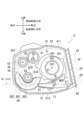
- FIG. 3 is a schematic diagram showing the case 6 viewed from the second cover 8 side.
- the case 6 includes a cylindrical peripheral wall portion 61 and a partition wall portion 62.
- FIG. 3 is a schematic diagram showing the case 6 viewed from the second cover 8 side.
- the case 6 includes a cylindrical peripheral wall portion 61 and a partition wall portion 62.
- FIG. 3 is a schematic diagram showing the case 6 viewed from the second cover 8 side.
- the case 6 includes a cylindrical peripheral wall portion 61 and a partition wall portion 62.
- the partition wall 62 divides the space inside the peripheral wall 61 into two in the direction of the rotation axis X1.
- One side of the partition wall portion 62 in the direction of the rotation axis X1 is the first chamber S1, and the other side is the third chamber S3.
- the opening on the side of the first chamber S1 is sealed with a second cover 8 (torque converter cover) to form a closed first chamber S1.
- the opening on the third chamber S3 side is sealed with the first cover 7 (side cover) to form a closed third chamber S3.
- the forward/reverse switching mechanism 2, the speed reduction mechanism 4, and the differential gear 5 are housed in the first chamber S1.
- the variator 3 is accommodated in the third chamber S3.
- a housing portion 68 forming a second chamber S2 is attached to the outer periphery of the peripheral wall portion 61 on the vehicle front side.
- the housing portion 68 is provided with an opening facing toward the front side of the vehicle.
- the opening of the accommodating portion 68 is sealed with the third cover 9 to form a closed second chamber S2.
- the second chamber S2 is provided with a control valve CV and an electric oil pump EOP.
- the control valve CV has a basic configuration in which a separate plate 920 is sandwiched between valve bodies 921, 921.
- a hydraulic control circuit (not shown) is formed inside the control valve CV.
- the hydraulic control circuit is provided with a solenoid that is driven based on a command from a control device (not shown) and a pressure regulating valve SP (spool valve) that is operated by signal pressure generated by the solenoid.
- the control valve CV is placed vertically with the stacking direction of the valve bodies 921, 921 aligned with the longitudinal direction of the vehicle. As shown in FIG. 3, in the second chamber S2 formed within the housing portion 68, the control valve CV is vertically placed so as to satisfy the following conditions.
- a plurality of pressure regulating valves SP (spool valves) in the control valve CV are lined up in the vertical line VL direction (vertical direction) based on the installation state of the power transmission device 1 in the vehicle V,
- spool valve The direction of forward and backward movement of is along the horizontal direction.
- vertical installation refers to a state in which the control valve CV is installed in such a direction that the spool valve within the control valve is shifted in position in the vertical line VL direction.
- the stacking direction of the valve bodies 921, 921 is oriented along the horizontal direction (vehicle longitudinal direction).
- control valve CV is vertically placed within the second chamber S2 while ensuring that the forward and backward movement of the spool valve is not obstructed. Therefore, the second chamber S2 is prevented from increasing in size in the longitudinal direction of the vehicle.
- the partition wall portion 62 is located inside the joint portion 611.
- the partition wall portion 62 of the case 6 is provided in a range that crosses the rotation axis (rotation axis X1 to rotation axis X4) of the power transmission mechanism.
- the partition wall portion 62 is provided in a direction substantially perpendicular to the rotation axis (rotation axis X1 to rotation axis X4).
- the partition wall portion 62 is provided with through holes 621, 622, 624 and a support hole 623.
- the through hole 621 is formed around the rotation axis X1.
- a cylindrical support wall 631 surrounding the through hole 621 and a peripheral wall 641 surrounding the outer periphery of the support wall 631 with an interval are provided on the side of the partition wall 62 on the first chamber S1 side (the front side in the drawing).
- a cylindrical support wall 631 surrounding the through hole 621 and a peripheral wall 641 surrounding the outer periphery of the support wall 631 with an interval are provided.
- the support wall portion 631 and the peripheral wall portion 641 protrude toward the front side of the paper (the second cover 8 side in FIG. 1).
- a region 651 between the support wall portion 631 and the peripheral wall portion 641 is a cylindrical space that accommodates a piston (not shown) of the forward/reverse switching mechanism 2, a friction plate (forward clutch, reverse brake), and the like.
- the input shaft 34 (see FIG. 2) of the primary pulley 31 is rotatably supported on the inner periphery of the support wall portion 631 via a bearing B.
- the through hole 622 is formed around the rotation axis X2.
- the rotation axis X2 is located diagonally above the rear side of the vehicle when viewed from the rotation axis X1.
- the support hole 623 is a bottomed hole formed around the rotation axis X3.
- the rotation axis X3 is located diagonally above the rear side of the vehicle when viewed from the rotation axis X1, and diagonally below the rear side of the vehicle when viewed from the rotation axis X2.
- the through hole 624 is formed around the rotation axis X4.
- the rotation axis X4 is located diagonally downward on the rear side of the vehicle when viewed from the rotation axis X1, diagonally downward on the rear side of the vehicle when viewed from the rotation axis X2, and diagonally downward on the rear side of the vehicle when viewed from the rotation axis X3. It is located diagonally below the front of the vehicle.
- a cylindrical support wall portion 634 surrounding the through hole 624 is provided on the surface of the partition wall portion 62 on the first chamber S1 side (the front side in the drawing).
- the differential case 50 of the differential device 5 is rotatably supported on the inner periphery of the support wall portion 634 via a bearing B.
- a drive shaft 55A (see FIG. 2) extending from the differential case 50 passes through the through hole 624.
- a ring-shaped final gear 45 is fixed to the outer periphery of the differential case 50 when viewed from the direction of the rotation axis X4.
- Final gear 45 rotates around rotation axis X4 together with differential case 50.
- a baffle plate 66 is attached below the through hole 624 on the surface of the partition wall 62 on the first chamber S1 side (the front side in the paper).
- the baffle plate 66 has a semicircular shape with the curved surface facing downward when viewed from the direction of the rotation axis X4.
- the baffle plate 66 includes side plate portions 661, 661 (see FIG. 9) that cover the side surfaces of the final gear 45 in the rotation axis X4 direction, an arcuate wall portion 662 that covers the side surfaces of the differential case 50 in the rotation axis X4 direction, and an outer periphery of the final gear 45. It has a peripheral wall part 663 that covers.
- the region on the vehicle front side of the arcuate wall portion 662 of the baffle plate 66 and below the arcuate peripheral wall portion 641 serves as the storage portion 67 for the strainer 10 and the mechanical oil pump MOP. ing.
- the housing portion 67 is located at the lower part of the case 6 (housing HS). Therefore, oil OL used for driving and cooling the components of the power transmission mechanism is stored in the storage portion 67.
- the accommodating portion 67 is a space with a bottom, and in the accommodating portion 67, a partition wall portion 62 serving as a bottom wall is located on the back side of the paper in FIG.
- the strainer 10 is provided with the oil OL suction port 13 facing the bottom wall portion 613 of the case 6 .
- the pump mechanical oil pump MOP, electric oil pump EOP
- the oil OL stored in the lower part (accommodating portion 67) of the first chamber S1 is sucked through the strainer 10. It is designed to be supplied to the pump side.
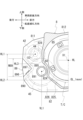
- FIG. 4 is a plan view of the second cover 8 viewed from the case 6 side.
- the region of the joint portion 811 is shown with cross hatching.
- FIG. 5 is a plan view of the second region 826 side of the second cover 8 viewed from the engine ENG side.
- a region of the joint portion 812 with the engine ENG side is shown with crossed hatching.
- the positions of the outer peripheries of the final gear 45 and idler gear 42 located on the back side of the partition wall 82 in the drawing, and the positions of the bottom wall 891 and the first wall 895 forming the recess are shown by imaginary lines.
- FIG. 6 is a diagram schematically showing a cross section of the second cover 8 taken along line AA in FIG. 4. As shown in FIG.
- the second cover 8 includes a cylindrical peripheral wall portion 81 and a partition wall portion 82.
- the partition wall portion 82 is provided in a range that crosses the rotation axis (rotation axis X1 to rotation axis X4) of the power transmission mechanism.
- the end surface of the peripheral wall portion 81 on the case 6 side serves as a joint portion 811 with the case 6.
- the partition wall portion 82 is located inside the joint portion 811 .
- the partition wall portion 82 is provided with through holes 821 and 824 and support holes 822 and 823.
- the partition wall portion 82 has a first region 825 and a second region 826.
- the first region 825 is a substantially circular region centered on the rotation axis X1.
- the first region 825 bulges toward the front side of the paper (towards the first chamber S1).
- a torque converter T/C is housed on the opposite side (engine ENG side) of the first region 825 (see FIG. 6).
- the through hole 821 located approximately at the center of the first region 825 is formed around the rotation axis X1.
- a cylindrical support wall portion 831 surrounding the through hole 821 is provided on the surface of the partition wall portion 82 on the first chamber S1 side (the front side in the drawing).
- the second region 826 is a region of the partition wall section 82 excluding the first region 825. It is located on the rear side of the vehicle when viewed from the rotation axis X1.
- the second region 826 is provided with support holes 822 and 823 and a through hole 824.
- the support hole 822 is a bottomed hole formed around the rotation axis X2.
- the output shaft 33 (see FIG. 2) of the secondary pulley 32 is rotatably supported on the inner periphery of the support hole 822 via a bearing B.
- the support hole 823 is a bottomed hole formed around the rotation axis X3.
- a cylindrical support wall portion 833 surrounding the support hole 823 is provided in the second region 826.
- the support wall portion 833 protrudes toward the front side of the paper.
- the idler shaft 44 (see FIG. 2) of the speed reduction mechanism 4 is rotatably supported on the inner periphery of the support wall portion 833 via a bearing B.
- the through hole 824 is formed around the rotation axis X4.
- a cylindrical support wall portion 834 surrounding the through hole 824 is provided in the second region 826.
- the support wall portion 834 protrudes toward the front side of the paper.
- the differential case 50 (see FIG. 2) of the differential device 5 is rotatably supported on the inner periphery of the support wall portion 834 via a bearing B.
- a second wall portion 896 constituting a recessed portion 89 which will be described later, is located on the rear side of the vehicle relative to the rotation axis X4 and below the rotation axis X3.
- the second wall portion 896 is located closer to the front of the paper than the second region 826.
- the region of the second wall portion 896 when viewed from the direction of the rotation axis X4 is formed by recessing a part of the second region 826 of the second cover 8 toward the front side (the case 6 side) in the drawing.
- a joint portion 812 with the engine ENG is provided along the outer periphery of the torque converter T/C.
- the inside of the joint portion 812 serves as a housing portion 85 for the torque converter T/C (see FIGS. 5 and 6).
- the second region 826 is located on the rear side of the vehicle when viewed from the housing portion 85.
- the through hole 824 opens below the horizontal line HL passing through the rotation axis X1.
- the drive shaft 55B extending from the differential case 50 passes through this through hole 824 (see FIG. 2).
- a support portion 828 for the idler shaft 44 is located obliquely above the rear side of the vehicle when viewed from the through hole 824 .
- the support portion 828 is located on the back side of the support hole 823 (see FIG. 4). It is provided around the rotation axis X3.
- the support portion 828 bulges toward the front in the drawing.
- a recess 89 is provided on the rear side of the vehicle when viewed from the through hole 824.
- the recessed portion 89 is formed by recessing a part of the second region 826 located on the rear side of the vehicle toward the back side of the paper (case 6 side) and the right side in the figure (the front side of the vehicle).
- the recess 89 is formed in a tapered shape with a width W89 in the vertical line VL direction that becomes narrower toward the front of the vehicle.
- the recess 89 is a space surrounded by three walls (a bottom wall 891, a first wall 895, and a second wall 896).
- the recess 89 is provided with openings facing the engine ENG side (the front side in the drawing) and the rear side of the vehicle.
- the recess 89 is located outside the partition wall 82 (second region 826).
- the first wall portion 895 is located on the baffle plate 66 (arc-shaped wall portion 662) side of the recess 89 in the vehicle longitudinal direction.
- the second wall portion 896 is located on the baffle plate 66 (side plate portion 661) and final gear 45 side of the recess 89 in the vehicle width direction.
- a connecting portion 897 between the bottom wall portion 891 and the first wall portion 895 is arranged at a position overlapping the final gear 45 when viewed from the direction of the rotation axis X4. Furthermore, when viewed from the direction of the rotation axis X4, the first wall portion 895 extends diagonally below the idler gear 42 on the vehicle rear side. When viewed from the direction of the rotation axis X4, the first wall portion 895 is inclined toward the rear of the vehicle as it moves upward away from the bottom wall portion 891. The first wall portion 895 is provided in a positional relationship that does not overlap the idler gear 42 when viewed from the direction of the rotation axis X4.
- the bottom of the recess 89 is located outside the first wall 895 and the second wall 896 and extends between the first wall 895 and the second wall 896.
- a wall portion 891 is located.
- the bottom wall portion 891 is provided with an insertion port 890 for the charging pipe CP.
- the insertion port 890 penetrates the bottom wall portion 891 in the thickness direction.
- the insertion port 890 is provided so as to satisfy the following conditions. (a) A straight line L891 along the opening direction of the insertion port 890 intersects the straight line Lx connecting the rotation axis X3 and the rotation axis X4 below the rotation axis X4 (see FIG. 7).
- the insertion port 890 is provided in a positional relationship that overlaps the baffle plate 66 (arc-shaped wall portion 662) (see FIG. 6).
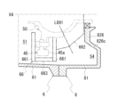
- FIG. 9 is a diagram schematically showing a cross section of the second cover 8 taken along the line AA in FIG. 6.
- the positions of the differential case 50 and the baffle plate 66, which are located in the lower part of the first chamber S1 on the front side of the plane of the paper relative to the cut surface, are shown by imaginary lines.
- a lower end 826c of the second region 826 is provided with a space between it and the peripheral wall 81 in the radial direction of the rotation axis X4.
- an oil trap S4 is formed in a lower region where the differential case 50 is located. As shown in FIG. 6, the oil trap S4 extends in the vehicle longitudinal direction. The oil trap S4 is a space with an opening facing the case 6 side (right side in the figure). Therefore, the oil capture portion S4 communicates with the first chamber S1 and constitutes a part of the first chamber S1.
- the oil trap S4 is located on an extension of the straight line L891 along the opening direction of the insertion port 890. Therefore, when the charging pipe CP is inserted through the insertion port 890 shown in FIG. 8, the distal end side of the charging pipe CP is arranged to face the oil trapping portion S4.
- the gauge part G1 of the oil level gauge G is inserted straight toward the oil trapping part S4 (see FIGS. 8 and 9).
- the baffle plate 66 is located on the case 6 side (left side in the figure), so the inserted oil level gauge It is designed not to interfere with the body.
- the insertion port 890 of the charging pipe CP opens closer to the engine ENG than the baffle plate 66 (see FIG. 6). Therefore, when the oil level gauge G is inserted through the charging pipe CP, the oil level gauge G interferes with the differential case 50 and the final gear 45 because the sides of the differential case 50 and the final gear 45 are covered with the baffle plate 66. (See Figure 8). Furthermore, the idler gear 42 is located on the vehicle front side of the insertion port 890 (see FIG. 6). Since the insertion port 890 opens below the lower edge of the idler gear 42, even if the oil level gauge G is inserted through the charging pipe CP, the oil level gauge G does not interfere with the idler gear 42. It has become.
- the recess 89 is provided to utilize this space, and the charging pipe CP is inserted into the bottom wall 891 of the recess 89.
- a port 890 is provided. Since the accommodating portion 67, which is a storage space for the oil OL, can be accessed from the insertion port 890 by the shortest distance, the charging pipe CP inserted from the insertion port 890 can have a simple shape with less curvature.
- the oil level gauge G when the oil level gauge G is pulled out from the charging pipe CP, it is possible to suitably prevent the gauge part G1 from interfering with the inner periphery of the charging pipe CP, thereby preventing adhering oil from being scraped off. Therefore, the oil level can be determined appropriately.
- the power transmission device 1 for the vehicle V is A power transmission mechanism (torque converter T/C, forward/reverse switching mechanism 2, variator 3, deceleration mechanism 4, differential gear 5) that transmits the driving force from the engine ENG (drive source) to the drive wheels WH, WH; a housing HS that accommodates a power transmission mechanism; a control valve CV that regulates the pressure of oil supplied to the power transmission mechanism; an input shaft 20 (input shaft) of a power transmission mechanism; an idler shaft 44 (intermediate shaft) of the power transmission mechanism; Drive shafts 55A and 55B (output shafts) of the power transmission mechanism, It has an insertion port 890 for charging pipe CP.
- the drive shafts 55A and 55B are located on the rear side of the vehicle V relative to the input shaft 20.
- the idler shaft 44 (third shaft) is located above the drive shafts 55A and 55B.
- the control valve CV is vertically placed on the vehicle front side of the input shaft 20.
- the housing HS is provided with a recessed portion 89 in which the housing HS is recessed inward, in a region on the rear side of the vehicle than the drive shafts 55A, 55B and below the idler shaft 44.
- An insertion port 890 is provided in a bottom wall portion 891 (bottom portion) of the recess 89 when viewed from above in the direction of the vertical line VL.
- the drive shafts 55A, 55B which are output shafts, and below the idler shaft 44 (intermediate shaft) to allow insertion of the charging pipe CP.
- the storage section 67 which is the storage space for the oil OL, can be accessed in the shortest distance, so the charging pipe CP inserted through the insertion port 890 has a simple shape with less curvature. be able to.
- the gauge part G1 may interfere with the inner circumference of the charging pipe CP. , adhering oil may be scraped off.
- the possibility of such a situation occurring can be reduced. Therefore, the oil level can be determined appropriately.
- a rotating body (differential case 50, final gear 45) that is provided coaxially with the drive shafts 55A, 55B and participates in rotation transmission between the drive shafts 55A, 55B and the idler shaft 44; It has a baffle plate 66 (cover) that covers one side of the rotating body in the axial direction of the drive shafts 55A, 55B.
- the insertion port 890 is provided in a positional relationship that overlaps the baffle plate 66 when viewed from the radial direction of the drive shafts 55A, 55B (fourth shaft).
- the insertion port 890 and the baffle plate 66 are arranged in an overlapping positional relationship when viewed from the horizontal line direction (arrow B direction) along the longitudinal direction of the vehicle, as shown in FIG.
- the baffle plate 66 (cover) can prevent interference between the charging pipe CP inserted from the insertion port 890 and the rotating body (the differential case 50, the final gear 45).
- the baffle plate 66 can prevent the oil OL stirred by the rotation of the rotating body from moving to the accommodating portion 67 into which the charging pipe CP is inserted.
- the oil OL stirred by the rotation of the rotating body contains many air bubbles.
- the air bubbles contained in the oil OL will affect the position of the oil attached to the gauge part G1 of the oil level gauge G. There is a possibility that In such a case, detection of the position of the oil OL within the housing HS may become uncertain. With the above configuration, the oil OL containing air bubbles is suppressed from reaching the gauge part G1, so that the position of the oil OL can be detected more appropriately.
- the idler shaft 44 (intermediate shaft) is located toward the rear of the vehicle than the drive shafts 55A, 55B (output shafts).
- a straight line L891 along the opening direction of the insertion port 890 is below a straight line Lx connecting the idler shaft 44 (intermediate shaft) and the drive shafts 55A, 55B (output shaft) and the drive shafts 55A, 55B. They are located at the intersections on the sides.
- a straight line L891 along the opening direction of the insertion port 890 is connected to a straight line Lx connecting the idler shaft 44 (intermediate shaft) and the drive shafts 55A, 55B (output shaft), and the drive shafts 55A, 55B (output shaft). It is located at the location where it intersects on the lower side.
- the charging pipe CP inserted from the insertion port 890 can reach the storage section 67, which is the storage section for the oil OL, without interfering with the rotating body. In particular, interference with the idler gear 42 provided on the idler shaft 44 (intermediate shaft) can be prevented.
- the rotating bodies are the differential case 50 and the final gear 45 fixed to the outer periphery of the differential case 50.
- the idler shaft 44 includes a reduction gear 43 (transmission gear) that meshes with the final gear 45 and an idler gear 42 that participates in rotation transmission between the output shaft 33 (another intermediate shaft) of the secondary pulley 32. Ori, In the axial direction of the idler shaft 44, the idler gear 42 is located on one side of the reduction gear 43 where the baffle plate 66 is located.
- the insertion port 890 (recess 89) is provided in a positional relationship that overlaps the idler gear 42 when viewed from the rear side of the vehicle.
- the baffle plate 66 When viewed from the reduction gear 43, the baffle plate 66 is located on one side (engine side) where the idler gear 42 is located. The baffle plate 66 is located below the idler gear 42 in the vertical line VL direction (see FIG. 7). Therefore, since the insertion port 890 is provided in a positional relationship that overlaps the idler gear 42 and the baffle plate 66 when viewed from the rear side of the vehicle, the charging pipe CP inserted from the insertion port 890 can be connected to the differential case 50 and the idler gear 42. can be installed to avoid interference with the
- the recess 89 When viewed from the axial direction of the drive shafts 55A, 55B, the recess 89 includes a first wall 895 on the idler gear 42 side (see FIG. 6).
- the lower edge (connection portion 897) of the first wall portion 895 is located below the horizontal line HL3 passing through the lower edge of the idler gear 42 (see FIG. 5).
- the charging pipe CP inserted from the insertion port 890 is restricted from moving in the direction of interfering with the idler gear 42 (downward in FIG. 6) by the first wall portion 895. Therefore, the charging pipe CP inserted from the insertion port 890 can be suitably prevented from interfering with the idler gear 42.
- the recessed portion 89 When viewed from the rear side of the vehicle, the recessed portion 89 includes the second wall portion 896 on the final gear 45 side.
- the charging pipe CP inserted through the insertion port 890 is restricted from moving in the direction of interfering with the final gear 45 (rightward in FIG. 6) by the second wall portion 896. Therefore, it is possible to suitably prevent the charging pipe CP inserted from the insertion port 890 from interfering with the final gear 45.
- the baffle plate 66 (cover) is a side plate portion 661 (first cover portion) that covers the side surface 45a of the final gear 45 on the differential case 50 side; It has an arcuate wall portion 662 (second cover portion) that covers the lower outer periphery of the differential case 50.
- the baffle plate 66 is composed of a side plate part 661 that covers the side surface of the final gear 45 and an arcuate wall part 662 that covers the lower outer periphery of the differential case 50.
- the final gear 45 and the differential case 50 can be protected from interference with the charging pipe CP.
- the housing HS includes a case 6 that houses the power transmission mechanism, It has a second cover 8 (torque converter cover) that covers the opening of the case 6 on the torque converter T/C side.
- the recess 89 is provided in the second cover 8.
- the insertion port 890 can be provided at a position that avoids interference with the rotating element within the case 6.
- the charging pipe CP can be inserted into the insertion port 890 without causing the case 6 to bulge out significantly toward the vehicle rear side.
- the operability of the oil level gauge G when the power transmission device 1 is mounted on the vehicle V is not significantly impaired.
- the power transmission device 1 transmits the rotation of the engine ENG to the drive wheels WH, WH is illustrated, but the power transmission device 1 transmits the rotation of the engine ENG and the motor (rotating electric machine).
- the rotation may be transmitted to the drive wheels WH, WH.
- a one-motor, two-clutch type (the motor is arranged between the engine ENG and the power transmission device, the first clutch is arranged between the engine ENG and the motor, and the second clutch is arranged inside the power transmission device 1)
- It may also be a power transmission device of the following type.
- the power transmission device 1 has a speed change function, but the power transmission mechanism does not have a speed change function and simply decelerates (or may speed up). It's okay. If the power transmission device does not have a speed change function and is configured to decelerate the rotation of the motor and transmit it to the drive wheels WH, the oil OL for cooling the motor and the deceleration A hydraulic control circuit for supplying oil OL for lubricating the mechanism is arranged in the second chamber S2 together with the electric oil pump EOP. Further, in the above embodiment, the control unit of the power transmission device 1 is provided with the control valve CV, but the power transmission device 1 does not have a speed change mechanism, and the drive source is not the engine ENG. In the case of a motor (rotating electric machine), it may be a control unit including an inverter or the like that drives and controls the motor.
Landscapes
- Engineering & Computer Science (AREA)
- General Engineering & Computer Science (AREA)
- Mechanical Engineering (AREA)
- General Details Of Gearings (AREA)
Priority Applications (3)
| Application Number | Priority Date | Filing Date | Title |
|---|---|---|---|
| US18/847,007 US12486891B2 (en) | 2022-03-23 | 2023-03-23 | Power transmission device |
| JP2024509235A JP7584879B2 (ja) | 2022-03-23 | 2023-03-23 | 動力伝達装置 |
| CN202380028195.8A CN118900963A (zh) | 2022-03-23 | 2023-03-23 | 动力传递装置 |
Applications Claiming Priority (2)
| Application Number | Priority Date | Filing Date | Title |
|---|---|---|---|
| JP2022-047616 | 2022-03-23 | ||
| JP2022047616 | 2022-03-23 |
Publications (1)
| Publication Number | Publication Date |
|---|---|
| WO2023182456A1 true WO2023182456A1 (ja) | 2023-09-28 |
Family
ID=88101683
Family Applications (1)
| Application Number | Title | Priority Date | Filing Date |
|---|---|---|---|
| PCT/JP2023/011619 Ceased WO2023182456A1 (ja) | 2022-03-23 | 2023-03-23 | 動力伝達装置 |
Country Status (4)
| Country | Link |
|---|---|
| US (1) | US12486891B2 (https=) |
| JP (1) | JP7584879B2 (https=) |
| CN (1) | CN118900963A (https=) |
| WO (1) | WO2023182456A1 (https=) |
Cited By (2)
| Publication number | Priority date | Publication date | Assignee | Title |
|---|---|---|---|---|
| US20250207661A1 (en) * | 2022-03-23 | 2025-06-26 | Jatco Ltd | Power transmission device |
| US20250224029A1 (en) * | 2022-03-23 | 2025-07-10 | Jatco Ltd | Power transmission device |
Families Citing this family (1)
| Publication number | Priority date | Publication date | Assignee | Title |
|---|---|---|---|---|
| CN119053802A (zh) * | 2022-03-23 | 2024-11-29 | 加特可株式会社 | 动力传递装置以及液压装置 |
Citations (2)
| Publication number | Priority date | Publication date | Assignee | Title |
|---|---|---|---|---|
| JP2001296169A (ja) * | 2000-04-13 | 2001-10-26 | Mitsubishi Motors Corp | 液面検出装置 |
| JP2012057498A (ja) * | 2010-09-06 | 2012-03-22 | Honda Motor Co Ltd | 車両用エンジン |
Family Cites Families (9)
| Publication number | Priority date | Publication date | Assignee | Title |
|---|---|---|---|---|
| US5440951A (en) * | 1993-07-30 | 1995-08-15 | Kanzaki Kokyukoki Mfg. Co., Ltd. | Axle driving system |
| JP2007139142A (ja) * | 2005-11-22 | 2007-06-07 | Jatco Ltd | 自動変速機 |
| JP2007255369A (ja) * | 2006-03-24 | 2007-10-04 | Jatco Ltd | 変速機のオイルポンプ構造 |
| US9644722B2 (en) * | 2014-02-20 | 2017-05-09 | GM Global Technology Operations LLC | One mode continuously variable transmission |
| JP6299002B2 (ja) | 2014-02-27 | 2018-03-28 | ダイハツ工業株式会社 | オイルレベルゲージ |
| JP7238386B2 (ja) * | 2018-12-21 | 2023-03-14 | スズキ株式会社 | ハイブリッド車両用駆動装置 |
| US11859714B2 (en) * | 2019-07-25 | 2024-01-02 | Jatco Ltd | Power transmission device |
| WO2022009568A1 (ja) * | 2020-07-09 | 2022-01-13 | ジヤトコ株式会社 | 蓋状部品 |
| CN214775204U (zh) * | 2021-06-25 | 2021-11-19 | 捷信圣科(威海)新材料科技有限公司 | 一种越野车用汽车前桥 |
-
2023
- 2023-03-23 US US18/847,007 patent/US12486891B2/en active Active
- 2023-03-23 WO PCT/JP2023/011619 patent/WO2023182456A1/ja not_active Ceased
- 2023-03-23 JP JP2024509235A patent/JP7584879B2/ja active Active
- 2023-03-23 CN CN202380028195.8A patent/CN118900963A/zh active Pending
Patent Citations (2)
| Publication number | Priority date | Publication date | Assignee | Title |
|---|---|---|---|---|
| JP2001296169A (ja) * | 2000-04-13 | 2001-10-26 | Mitsubishi Motors Corp | 液面検出装置 |
| JP2012057498A (ja) * | 2010-09-06 | 2012-03-22 | Honda Motor Co Ltd | 車両用エンジン |
Cited By (4)
| Publication number | Priority date | Publication date | Assignee | Title |
|---|---|---|---|---|
| US20250207661A1 (en) * | 2022-03-23 | 2025-06-26 | Jatco Ltd | Power transmission device |
| US20250224029A1 (en) * | 2022-03-23 | 2025-07-10 | Jatco Ltd | Power transmission device |
| US12504065B2 (en) * | 2022-03-23 | 2025-12-23 | Jatco Ltd | Power transmission device |
| US12553512B2 (en) * | 2022-03-23 | 2026-02-17 | Jatco Ltd | Power transmission device |
Also Published As
| Publication number | Publication date |
|---|---|
| US20250207660A1 (en) | 2025-06-26 |
| JP7584879B2 (ja) | 2024-11-18 |
| JPWO2023182456A1 (https=) | 2023-09-28 |
| CN118900963A (zh) | 2024-11-05 |
| US12486891B2 (en) | 2025-12-02 |
Similar Documents
| Publication | Publication Date | Title |
|---|---|---|
| WO2023182456A1 (ja) | 動力伝達装置 | |
| JP7584877B2 (ja) | 動力伝達装置 | |
| WO2010070995A1 (ja) | 車両用駆動装置 | |
| JP7580900B2 (ja) | 動力伝達装置 | |
| WO2023182449A1 (ja) | 動力伝達装置 | |
| JP7604087B2 (ja) | 動力伝達装置 | |
| JP7596055B2 (ja) | 動力伝達装置 | |
| JP7584878B2 (ja) | 動力伝達装置および油圧装置 | |
| JP2016223452A (ja) | 車両用駆動装置 | |
| JP7618375B2 (ja) | 動力伝達装置 | |
| WO2023182444A1 (ja) | 動力伝達装置 | |
| WO2023182454A1 (ja) | 動力伝達装置 | |
| WO2023182446A1 (ja) | 動力伝達装置 | |
| WO2023182450A1 (ja) | 動力伝達装置 | |
| JP2023141341A (ja) | 動力伝達装置 | |
| JP7117831B2 (ja) | 自動変速機 | |
| JP7618376B2 (ja) | 動力伝達装置 | |
| KR20190008093A (ko) | 자동 변속기 | |
| JP2019019888A (ja) | 自動変速機および自動変速機の製造方法 | |
| JP7812183B2 (ja) | 動力伝達装置 | |
| JP7547024B2 (ja) | 装置 | |
| JP6179272B2 (ja) | 車両用変速機 | |
| WO2024004407A1 (ja) | 油圧回路 |
Legal Events
| Date | Code | Title | Description |
|---|---|---|---|
| 121 | Ep: the epo has been informed by wipo that ep was designated in this application |
Ref document number: 23775050 Country of ref document: EP Kind code of ref document: A1 |
|
| WWE | Wipo information: entry into national phase |
Ref document number: 18847007 Country of ref document: US |
|
| WWE | Wipo information: entry into national phase |
Ref document number: 202380028195.8 Country of ref document: CN |
|
| ENP | Entry into the national phase |
Ref document number: 2024509235 Country of ref document: JP Kind code of ref document: A |
|
| NENP | Non-entry into the national phase |
Ref country code: DE |
|
| 122 | Ep: pct application non-entry in european phase |
Ref document number: 23775050 Country of ref document: EP Kind code of ref document: A1 |
|
| WWP | Wipo information: published in national office |
Ref document number: 18847007 Country of ref document: US |