WO2023182453A1 - Dispositif de transmission de puissance - Google Patents
Dispositif de transmission de puissance Download PDFInfo
- Publication number
- WO2023182453A1 WO2023182453A1 PCT/JP2023/011616 JP2023011616W WO2023182453A1 WO 2023182453 A1 WO2023182453 A1 WO 2023182453A1 JP 2023011616 W JP2023011616 W JP 2023011616W WO 2023182453 A1 WO2023182453 A1 WO 2023182453A1
- Authority
- WO
- WIPO (PCT)
- Prior art keywords
- power transmission
- chamber
- electric pump
- transmission device
- recess
- Prior art date
Links
- 230000005540 biological transmission Effects 0.000 title claims abstract description 107
- 230000007246 mechanism Effects 0.000 claims abstract description 48
- 230000002093 peripheral effect Effects 0.000 claims description 47
- 238000005192 partition Methods 0.000 claims description 15
- 230000013011 mating Effects 0.000 claims description 7
- 230000001105 regulatory effect Effects 0.000 description 15
- 238000010586 diagram Methods 0.000 description 10
- 238000009434 installation Methods 0.000 description 7
- 230000005484 gravity Effects 0.000 description 3
- 239000004575 stone Substances 0.000 description 3
- 230000012447 hatching Effects 0.000 description 2
- 230000004308 accommodation Effects 0.000 description 1
- 230000015572 biosynthetic process Effects 0.000 description 1
- 238000001816 cooling Methods 0.000 description 1
- 230000001050 lubricating effect Effects 0.000 description 1
- 230000008961 swelling Effects 0.000 description 1
- 238000004804 winding Methods 0.000 description 1
Images


Classifications
-
- F—MECHANICAL ENGINEERING; LIGHTING; HEATING; WEAPONS; BLASTING
- F04—POSITIVE - DISPLACEMENT MACHINES FOR LIQUIDS; PUMPS FOR LIQUIDS OR ELASTIC FLUIDS
- F04B—POSITIVE-DISPLACEMENT MACHINES FOR LIQUIDS; PUMPS
- F04B53/00—Component parts, details or accessories not provided for in, or of interest apart from, groups F04B1/00 - F04B23/00 or F04B39/00 - F04B47/00
-
- F—MECHANICAL ENGINEERING; LIGHTING; HEATING; WEAPONS; BLASTING
- F16—ENGINEERING ELEMENTS AND UNITS; GENERAL MEASURES FOR PRODUCING AND MAINTAINING EFFECTIVE FUNCTIONING OF MACHINES OR INSTALLATIONS; THERMAL INSULATION IN GENERAL
- F16H—GEARING
- F16H57/00—General details of gearing
- F16H57/02—Gearboxes; Mounting gearing therein
Definitions
- the present invention relates to a power transmission device.
- Patent Document 1 discloses a drive device for a vehicle.
- the electric oil pump is disposed at the bottom of the case with a portion exposed to the outside of the case.
- an external connector for power supply is provided at the top of the case.
- a power supply cable that connects the electric oil pump and the external connector is routed from the bottom to the top of the case.
- Components of the drive device such as a rotating body, are provided within the case.
- the power supply cable must be routed while avoiding interference with the components. Therefore, the routing of the power supply cable becomes complicated. Therefore, there is a need to make it easier to route the power supply cable within the case.
- An aspect of the present invention is a case that accommodates a power transmission mechanism; a control valve that controls hydraulic pressure supplied to the power transmission mechanism;
- a power transmission device comprising: an electric pump that supplies oil to the control valve;
- the said case is a first chamber that accommodates the power transmission mechanism; a second chamber disposed adjacent to the first chamber,
- the control valve and the electric pump are arranged vertically in the second chamber,
- a first recess that is recessed from above the electric pump toward the electric pump is provided in a region that overlaps the electric pump when viewed from above along the rotation axis of the electric pump
- the connector of the electric pump is a power transmission device in which a connecting portion with a mating connector is disposed within the first recess so as to face upward.
- the power supply cable can be more easily routed within the case.
- FIG. 1 is a schematic diagram showing a schematic configuration of a power transmission device.
- FIG. 2 is a schematic diagram of the case viewed from the first cover side.
- FIG. 3 is a schematic diagram of the housing section viewed from the front side of the vehicle.
- FIG. 4 is a sectional view of a main part of the housing.
- FIG. 5 is a sectional view of a main part of the housing.
- FIG. 6 is a sectional view of a main part of the housing.
- FIG. 7 is a sectional view of a main part of the housing.
- FIG. 8 is a sectional view of a main part of the housing.
- the power transmission device is a device having at least a power transmission mechanism, and the power transmission mechanism is, for example, at least one of a gear mechanism, a differential gear mechanism, and a speed reduction mechanism.
- the power transmission device 1 has a function of transmitting the output rotation of the engine, but the power transmission device 1 transmits the output rotation of at least one of the engine and the motor (rotating electric machine). It's fine as long as it's something you do.
- “Overlapping in a predetermined direction” means that a plurality of elements are lined up in a predetermined direction, and has the same meaning as "overlapping in a predetermined direction.”
- the "predetermined direction” is, for example, an axial direction, a radial direction, a gravity direction, a vehicle longitudinal direction, or the like. If a drawing shows multiple elements (parts, parts, etc.) lining up in a predetermined direction, there is a sentence in the description explaining that they overlap when viewed in the predetermined direction. It can be considered as.
- “Do not overlap when viewed in a predetermined direction” and “offset when viewed in a predetermined direction” mean that multiple elements are not lined up in a predetermined direction, and "do not overlap in a predetermined direction” , is synonymous with the expression “offset in a predetermined direction”.
- the "predetermined direction” is, for example, an axial direction, a radial direction, a gravity direction, a vehicle longitudinal direction (vehicle forward direction, vehicle backward direction), or the like. If a drawing shows that multiple elements (parts, parts, etc.) are not lined up in a predetermined direction, there is a sentence in the description explaining that they do not overlap when viewed in a predetermined direction. It can be considered as.
- the first element (component, section, etc.) is located between the second element (component, section, etc.) and the third element (component, section, etc.) when viewed from a predetermined direction" means In this case, the first element can be observed to be between the second and third elements.
- the "predetermined direction" includes an axial direction, a radial direction, a direction of gravity, a vehicle running direction (vehicle forward direction, vehicle backward direction), and the like.
- vehicle forward direction vehicle backward direction
- the first element is located between the second element and the third element when viewed in the radial direction. It can be said that it is located.
- Axial direction means the axial direction of the rotating shaft of the components that constitute the power transmission device.
- Ring direction means a direction perpendicular to the rotational axis of the components constituting the power transmission device.
- the parts are, for example, a motor, a gear mechanism, a differential gear mechanism, etc.
- “Vertical installation” of a control valve means that in the case of a control valve that has a basic configuration with a separate plate sandwiched between the valve bodies, the valve body of the control valve is placed horizontally with respect to the installation state of the power transmission device in the vehicle. This means that they are laminated in the same direction.
- the term "horizontal direction” as used herein does not mean the horizontal direction in a strict sense, but also includes cases where the stacking direction is tilted with respect to the horizontal line.
- vertical installation of a control valve means that the multiple pressure regulating valves (valve bodies) in the control valve are arranged in the vertical line VL direction based on the installation state of the power transmission device in the vehicle. This means that the valve is in place.
- a plurality of pressure regulating valves are arranged in the direction of the vertical line VL means that the pressure regulating valves in the control valve are arranged with their positions shifted in the direction of the vertical line VL.
- the plurality of pressure regulating valves do not need to be strictly lined up in a line in the vertical line VL direction.
- the plurality of pressure regulating valves are shifted in the direction of stacking of the valve bodies, and the vertical line VL They may be lined up in the same direction.
- the plurality of pressure regulating valves do not need to be lined up at intervals in the vertical line VL direction.
- the plurality of pressure regulating valves do not need to be adjacent to each other in the vertical line VL direction.
- pressure regulating valves lined up in the vertical line VL direction are arranged with their positions shifted in the stacking direction (horizontal line direction) of the valve body, the pressure regulating valves lined up in the vertical line VL direction are shifted when viewed from the stacking direction.
- This also includes cases where adjacent pressure regulating valves are provided in a positional relationship that partially overlaps.
- the multiple pressure regulating valves in the control valve are arranged in such a way that the moving direction of the valve body (spool valve) of the pressure regulating valve is along the horizontal direction.
- the moving direction of the valve body (spool valve) in this case is not limited to the horizontal direction in the strict sense.
- the moving direction of the valve body (spool valve) in this case is a direction along the rotation axis X of the power transmission device. In this case, the rotation axis X direction and the sliding direction of the valve body (spool valve) are the same.
- FIG. 1 is a schematic diagram illustrating a schematic configuration of a power transmission device 1.
- a power transmission device 1 mounted on a vehicle V has a housing HS that accommodates a power transmission mechanism.
- the housing HS includes a case 6, a first cover 7, a second cover 8, and a third cover 9.
- Power transmission mechanisms such as a torque converter T/C, a forward/reverse switching mechanism 2, a variator 3, a speed reduction mechanism 4, a differential device 5, and the like are housed inside the housing HS.
- an electric oil pump EOP, a mechanical oil pump MOP, a control valve CV, etc. are housed inside the housing HS.
- the output rotation of the engine ENG (drive source) is input to the forward/reverse switching mechanism 2 via the torque converter T/C.
- the rotation input to the forward/reverse switching mechanism 2 is input to the primary pulley 31 of the variator 3 in forward or reverse rotation.
- the rotation input to the primary pulley 31 is changed at a desired gear ratio, and the rotation is transferred to the output shaft 33 of the secondary pulley 32. is output from.
- the output rotation of the secondary pulley 32 is input to the differential device 5 (differential gear mechanism) via the reduction mechanism 4, and then transmitted to the drive wheels WH, WH via the left and right drive shafts 55A, 55B. .
- the forward/reverse switching mechanism 2 the torque converter T/C, and the output shaft of the engine ENG are arranged coaxially (concentrically) on the rotation axis X1 (first axis) of the primary pulley 31. Ru.
- the output shaft 33 of the secondary pulley 32 and the output gear 41 are coaxially arranged on the rotation axis X2 (second axis) of the secondary pulley 32.
- the idler gear 42 and the reduction gear 43 are coaxially arranged on a common rotation axis X3 (third axis).
- the final gear 45 and the drive shafts 55A and 55B are coaxially arranged on a common rotation axis X4 (fourth axis).
- these rotational axes X1 to X4 are set in a positional relationship in which they are parallel to each other.
- these rotational axes X1 to X4 will be collectively referred to as the rotational axis X of the power transmission device 1 (power transmission mechanism), if necessary.
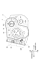
- FIG. 2 is a plan view of the case 6 viewed from the first cover 7 side.
- the power supply connector 90 is shown with cross hatching in order to make it easier to understand the arrangement of the power supply connector 90 located inside the first recess 10, which will be described later.
- the case 6 includes a cylindrical peripheral wall portion 61 and a partition wall portion 62.
- the peripheral wall portion 61 is provided along the rotation axis X of the power transmission device 1, and constitutes an outer wall portion of the power transmission device.
- the partition wall portion 62 is provided inside the peripheral wall portion 61 in a range that crosses the rotation axis (rotation axis X1 to rotation axis X4) of the power transmission device 1.
- the partition wall 62 divides the space inside the peripheral wall 61 into two in the direction of the rotation axis X1.
- One side of the partition wall portion 62 in the direction of the rotation axis X1 is the first chamber S1, and the other side is the third chamber S3.
- the case 6 and the second cover 8 are connected with bolts (not shown) with their joints 611 and 811 joined together. As a result, one opening of the case 6 is kept sealed by the second cover 8, forming a closed first chamber S1.
- the forward/reverse switching mechanism 2, the speed reduction mechanism 4, and the differential gear 5 are housed in the first chamber S1.
- the case 6 and the first cover 7 are connected with bolts (not shown) with their joints 612 and 711 joined together. As a result, the other opening of the case 6 is kept sealed by the first cover 7, forming a closed third chamber S3.
- the variator 3 is accommodated in the third chamber S3.
- through holes 621 and 622 are opened inside the peripheral wall portion 61.
- a through hole 624 is opened on the outside of the peripheral wall portion 61 .
- the through hole 621 is formed around the rotation axis X1.
- the input shaft 34 (see FIG. 1) of the primary pulley 31 passes through the through hole 621.
- the through hole 622 is formed around the rotation axis X2.
- the output shaft 33 (see FIG. 1) of the secondary pulley 32 passes through the through hole 622.
- the through hole 624 is formed around the rotation axis X4.
- the drive shaft 55A passes through the through hole 624.
- the primary pulley 31 is located lower than the secondary pulley 32 on the front side of the vehicle. Therefore, the portion of the peripheral wall portion 61 that surrounds the outer periphery of the primary pulley 31 is located furthest toward the front of the vehicle. A region of the peripheral wall portion 61 below the primary pulley 31 is recessed toward the rear of the vehicle so that it is located toward the rear of the vehicle as it goes downward.
- the first cover 7, which is assembled to the case 6 from the front side in the drawing also has a peripheral wall part 71 which is assembled to the peripheral wall part 61 from the direction of the rotation axis X (see FIG. 4).
- the peripheral wall portion 71 is formed in a shape that matches the peripheral wall portion 61 when viewed from the direction of the rotation axis X.
- a housing portion 68 is attached to the side surface on the front side of the vehicle.
- the housing portion 68 is provided with an opening facing toward the front side of the vehicle.
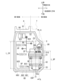
- FIG. 3 is a diagram of the housing portion 68 viewed from the front side of the vehicle.
- the second chamber S2 viewed from the front side of the vehicle is schematically shown together with other components (case 6 and first cover 7) of the housing HS.
- the region of the joint portion 683 located on the near side of the paper is shown with crossed hatching.
- the appearance of the control valve CV is schematically shown.
- a power supply line 97 connecting the electric oil pump EOP and the power supply connector 90 and a signal line 96 connecting the control connector 98 to the control valve CV and the electric oil pump EOP are schematically shown.
- the accommodating portion 68 includes a wall portion 682 and a peripheral wall portion 681 that surrounds the entire outer periphery of the wall portion 682 when viewed from the front side of the vehicle.
- the end surface of the peripheral wall portion 681 on the near side in the drawing forms a joint portion 683 with the third cover 9.
- a joint portion 911 on the third cover 9 side is joined to the joint portion 683 over the entire circumference.
- the accommodating portion 68 and the third cover 9 are connected with bolts (not shown) with their joint portions 683 and 911 joined together.
- a closed second chamber S2 is formed.
- the second chamber S2 accommodates a control valve CV and an electric oil pump EOP.
- the wall portion 682 of the housing portion 68 is oriented along the rotation axis X of the power transmission device 1.
- the accommodating portion 68 is formed to have a range in the rotation axis X direction (in the left-right direction in the figure) extending from a region adjacent to the peripheral wall portion 61 of the case 6 to the side of the first cover 7.
- approximately half the area (first area) on the second cover 8 side (right side in the figure) is integrated with the peripheral wall portion 61 on the case 6 side. ing.
- the approximately half area (second area) on the first cover 7 side is provided on the vehicle front side of the first cover 7 with a gap between it and the outer periphery of the first cover 7 .
- control valve CV has a basic configuration in which a separate plate 920 is sandwiched between valve bodies 921, 921.
- a hydraulic control circuit (not shown) is formed inside the control valve CV.
- the hydraulic control circuit is provided with a solenoid that is driven based on a command from a control device (not shown) and a pressure regulating valve (spool valve SP) that is operated by signal pressure generated by the solenoid.
- the control valve CV is placed vertically with the stacking direction of the valve bodies 921, 921 aligned with the longitudinal direction of the vehicle (in the paper, front to back direction). .
- the control valve CV is vertically placed so as to satisfy the following conditions.
- (a) A plurality of spool valves SP in the control valve CV are lined up in the vertical line VL direction (vertical direction) based on the installation state of the power transmission device 1 in the vehicle V,
- the direction Xp is along the horizontal direction.
- the forward and backward movement direction of the spool valve within the control valve is arranged along the horizontal direction. Furthermore, the spool valve within the control valve is arranged with its position shifted in the vertical line VL direction. Therefore, the forward and backward movement of the spool valve is not obstructed, and the second chamber S2 is prevented from increasing in size in the longitudinal direction of the vehicle.
- the control valve CV When viewed from the front side of the vehicle, the control valve CV has a substantially L-shape in which a notch 923 is provided in a substantially rectangular valve body 921.
- the notch 923 is provided to avoid interference with the electric oil pump EOP.
- a portion of the second cover 8 side (left side in the figure) of the electric oil pump EOP is accommodated in the notch 923.
- the length L_CV of the control valve CV in the direction of the vertical line VL is longer than the length L_OP of the electric oil pump EOP in the direction of the vertical line VL (L_CV>L_OP). Therefore, when viewed from the direction of the vertical line VL, a part of the electric oil pump EOP is provided in a positional relationship overlapping with the control valve CV.
- control valve CV and the electric oil pump EOP are lined up in the direction of the rotation axis X of the power transmission device 1 (in the left-right direction in the figure).
- the control valve CV is provided so as to overlap the case 6 when viewed from the front side of the vehicle.
- the electric oil pump EOP is provided so as to overlap the first cover 7 when viewed from the front side of the vehicle.
- the electric oil pump EOP has a basic configuration in which a control section 51, a motor section 52, and a pump section 53 are arranged in series in the direction of the rotation axis Z1 of the motor M.
- the electric oil pump EOP is provided with a rotation axis Z1 perpendicular to a rotation axis X of the power transmission device 1. In this state, the electric oil pump EOP is placed vertically in such a direction that the pump section 53 is located at the lower side of the second chamber S2, and the control section 51 is located at the upper side of the second chamber S2.
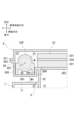
- FIG. 4 is a diagram schematically showing a cross section of the housing HS taken along line AA in FIG.
- a cross section of the bulging portion 69 in the second chamber S2 is schematically shown together with a cross section of the peripheral wall portion 71 of the first cover 7 located on the rear side of the vehicle.
- FIG. 5 is a diagram schematically showing a cross section of the housing HS taken along the line AA in FIG.
- a cross section around the motor portion 52 of the electric oil pump EOP is schematically shown.
- FIG. 6 is a diagram schematically showing a cross section of the housing HS taken along line BB in FIG. FIG.
- FIG. 6 schematically shows the first recess 10 provided in the accommodating portion 68 and the arrangement of the power supply connector 90 in the first recess 10.
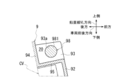
- FIG. 7 is a diagram schematically showing a cross section of the housing HS taken along line CC in FIG.
- FIG. 7 schematically shows the positional relationship between the first recess 10 provided in the accommodating portion 68 and the second recess 20 provided in the third cover 9.
- components bottom wall part 691, side wall part 694, side wall part 695, motor part 52
- FIG. 8 is a diagram schematically showing a cross section of the housing HS taken along line AA in FIG.
- FIG. 8 shows the area around the second recess 20 as seen from the engine ENG side.
- FIG. 4, FIG. 6, and FIG. 7 show how the power supply connector 90 and the electric oil pump EOP are connected via the power supply line 97, and how the control connector 98 and the electric oil pump EOP are connected via the signal line 96.
- the manner of connection with the control valve CV is simply described.
- a bulging portion 69 that functions as a housing portion for the electric oil pump EOP is provided in an area overlapping with the first cover 7 when viewed from the front side of the vehicle.
- the bulging portion 69 is formed by bulging the wall portion 682 toward the first cover 7 (the right side in FIG. 4).
- the bottom wall portion 691 of the bulging portion 69 is located at a distance of a depth D69 toward the first cover 7 when viewed from the wall portion 682.
- a portion of the electric oil pump EOP on the first cover 7 side is accommodated within the bulge 69.
- a portion of the electric oil pump EOP is accommodated in the bulging portion 69, so that the side edge 51a of the electric oil pump EOP on the vehicle front side and the side surface 921a of the control valve CV on the vehicle front side are substantially flush with each other.
- the electric oil pump EOP is arranged in the second chamber S2.
- the bulging portion 69 is formed with a length L69 in the rotation axis Z1 direction that can accommodate the electric oil pump EOP.
- the lower wall portion 692 of the bulging portion 69 is located on an extension of the peripheral wall portion 681 of the housing portion 68 .
- the upper wall portion 693 of the bulging portion 69 extends above the electric oil pump EOP toward the front side of the vehicle.
- the upper wall portion 693 is connected to the first wall portion 684 on the accommodating portion 68 side on the vehicle front side with respect to the rotation axis Z1.
- a first recess 10 is formed above the bulge 69 in the direction of the rotation axis Z1.
- the first recess 10 has a part of the area that overlaps with the electric oil pump EOP when viewed from the rotation axis Z1 direction, a lower side in the rotation axis Z1 direction, and a vehicle front side (upper side in the figure). It is a space created by recessing the area. That is, in the vertical line VL direction (vertical direction) along the rotation axis Z1 of the electric oil pump EOP in the housing part 68, the area located above the electric oil pump EOP in the housing part 68 is moved downward on the electric oil pump EOP side. It is formed by making a depression.
- the first recess 10 When viewed from the direction of the rotation axis Z1, the first recess 10 includes a first wall 684 and a second wall 685 on the accommodating part 68 side, a partition wall 62 on the case 6 side, and a peripheral wall 71 on the first cover 7 side. It is an enclosed space. Therefore, the first recess 10 is also surrounded by the first chamber S1, the second chamber S2, and the third chamber S3 in the housing HS.
- An upper wall portion 693 (see FIG. 4) of the bulging portion 69 for accommodating the electric oil pump EOP described above is located on the back side of the first recess 10 in the drawing.
- the first recess 10 is formed with its opening facing upward of the power transmission device 1. Furthermore, the first recess 10 is also open to one side in the vehicle width direction (to the left in FIG. 7).
- a power supply connector (power supply connector 90) is located within the first recess 10. As shown in FIG. 6, the power supply connector 90 has a connection portion 901 with a mating connector. The connection portion 901 is provided within the first recess 10 with the connection port for connecting to the mating connector facing upward.
- connection portion 901 of the power supply connector 90 When viewed from above in the direction of the vertical line VL, the connection portion 901 of the power supply connector 90 is provided in a positional relationship that completely overlaps the first recess 10. Further, the connecting portion 901 is provided at a position completely overlapping the first recess 10 when viewed from the direction of the rotation axis X of the power transmission device 1 (see FIG. 4). Therefore, the connecting portion 901 of the power feeding connector 90 is provided without protruding outward from the outer periphery of the housing HS (third cover 9, first cover 7, accommodating portion 68). That is, the connecting portion 901 is housed in the first recess 10 located inside the outer frame of the housing HS without protruding outward from the outer frame of the housing HS.
- the lower part of the connecting part 901 on the back side of the paper is connected to the base part 902 (see FIG. 6).
- the base 902 passes through a mounting hole 684a provided in the first wall 684.
- a region of the base portion 902 located within the second chamber S2 is connected to a connection portion 903 with the power supply line 97.
- the power supply connector 90 is electrically connected to the control section 51 (connection section 510) of the electric oil pump EOP via a power supply line 97.
- the attachment hole 684a in the first wall portion 684 is provided at a position upwardly away from the upper wall portion 693 of the bulging portion 69. As shown in FIG. Therefore, as shown in FIG. 3, the power supply connector 90 is located above the electric oil pump EOP.
- the length L_OP of the electric oil pump EOP in the direction of the vertical line VL is shorter than the length L_CV of the control valve CV in the direction of the vertical line VL (L_OP ⁇ L_CV). Therefore, if the lower end 925 of the control valve CV and the lower end 53a of the electric oil pump EOP are aligned in the second chamber S2, the available Space is secured.
- the power supply connector 90 is arranged in this available space.
- the electric oil pump EOP is arranged with the connecting portion 510 to the power supply line 97 facing upward in the vertical line VL direction. Therefore, the connection portion 510 is located directly below the power supply connector 90. Therefore, the connecting portion 510 of the electric oil pump EOP and the power supply connector 90 can be electrically connected over the shortest distance. This allows the power supply line 97 to be shortened. Furthermore, after the electric oil pump EOP is installed in the second chamber S2, the electric oil pump EOP and the power supply connector 90 can be easily connected.
- the first wall portion 684 to which the power supply connector 90 is attached extends upward along the rotation axis Z1 at a position overlapping the control valve CV when viewed from the vehicle width direction.
- the peripheral wall portion 91 of the third cover 9 is in contact with an area above the mounting hole 684a from the front side of the vehicle.
- the first wall portion 684 and the peripheral wall portion 91 are in contact with each other at a height exceeding the upper side 924 of the control valve CV.
- the first wall portion 684 extends on the extension of the joint portion 683 of the housing portion 68 in a direction approaching the control valve CV (to the right in the figure).
- the first wall portion 684 is connected to the second wall portion 685 on one side of the control valve CV in the vehicle width direction.
- the second wall portion 685 extends toward the first cover 7 (lower side in the figure) along the side edge of the control valve CV.
- the second wall portion 685 is connected to the wall portion 682 from the front side of the vehicle.
- the second wall portion 685 is provided in a positional relationship overlapping with the side wall portion 694 of the bulge portion 69 described above when viewed from the direction of the rotation axis Z1.
- the side wall portion 695 on the opposite side of the bulging portion 69 extends on the extension of the peripheral wall portion 681 of the housing portion 68 toward the first cover 7 side (lower side in the figure).
- the first wall portion 684 and the second wall portion 685 are recessed toward the vehicle front side than the wall portion 682, with the wall portion 682 supporting the control valve CV as a reference. It is located in such a way that By providing the first wall portion 684 and the second wall portion 685 in this manner, they participate in the formation of the first recess 10.
- the peripheral wall portion 71 of the first cover 7 is located on the rear side of the vehicle when viewed from the first wall portion 684.
- the first recess 10 is formed between the first wall 684 and the peripheral wall 71 in the vehicle longitudinal direction.
- the upper wall 693 of the bulge 69 described above is located on the back side of the first recess 10 in the drawing.
- the connecting portion 691a between the top wall portion 693 and the bottom wall portion 691 forms an arcuate outer periphery in a cross-sectional view along the rotation axis Z1.
- the connecting portion 691a has reached a position where it overlaps the peripheral wall portion 71 of the first cover 7 in the vertical line VL direction.
- the gap between the accommodating portion 68 and the peripheral wall portion 71 has a minimum width Wmin at the connecting portion 691a.
- the distance Wh between the bottom wall portion 691 and the peripheral wall portion 71 in the vehicle longitudinal direction becomes narrower as it goes upward in the vertical line VL direction.
- the region of the bottom wall portion 691 on the connection portion 691a side and the peripheral wall portion 71 are provided in an overlapping positional relationship. Therefore, even if a foreign object such as a stone is thrown up and enters between the bottom wall part 691 and the peripheral wall part 71 when the vehicle V equipped with the power transmission device 1 is running, it will not be located above the bulge part 69. It becomes difficult to reach the first recessed portion 10.
- the third cover 9 that covers the opening of the housing portion 68 on the vehicle front side includes a cover portion 92 having a size that covers the opening of the second chamber S2, a peripheral wall portion 91 that surrounds the entire outer periphery of the cover portion 92, has.
- a second recess 20 is formed in an area above the control valve CV in the direction of the rotation axis Z1.
- the second recess 20 is a space formed by recessing a part of the region of the third cover 9 that overlaps with the control valve CV toward the lower side and the rear side of the vehicle in the rotation axis Z1 direction. .
- the second recess 20 is located on the front side of the vehicle on the engine ENG (see FIG. 1) side when viewed from the first recess 10 described above. As shown in FIG. 7, the second recess 20 and the first recess 10 are shifted in position in the rotation axis X direction of the power transmission device 1 (horizontal direction in the figure) and in the longitudinal direction of the vehicle (vertical direction in the figure). It is provided.
- the second recess 20 includes a first wall 93 extending in the vehicle longitudinal direction, a second wall 94 extending in the vehicle width direction, and a first wall 94 extending in the vehicle width direction.
- the bottom wall portion 95 is formed between the portion 93 and the second wall portion 94 . Therefore, the second recess 20 opens to the front side of the vehicle and to the engine ENG side in the vehicle width direction (right side in FIG. 7).
- the first wall portion 93 is provided with a through hole 93a.
- the through hole 93a is provided with its opening facing the engine ENG side.
- a connector for control signals (control connector 98) is inserted into the through hole 93a from the engine ENG side (right side in FIG. 7).
- the control connector 98 has a connecting portion 981 with wiring for control signals located inside the second recess 20 on the outside of the third cover 9 .
- the control connector 98 is provided with the connecting portion 981 facing the engine ENG side, which is the opposite side from the electric oil pump EOP.
- the connecting portion 981 of the control connector 98 is provided in a positional relationship that completely overlaps the second recess 20 when viewed from above in the direction of the vertical line VL. Furthermore, the connecting portion 981 is provided at a position that completely overlaps the second recess 20 when viewed from the engine ENG side (see FIG. 8). Therefore, the connecting portion 981 of the control connector 98 is provided without protruding outward from the outer periphery of the housing HS (third cover 9).
- a signal line 96 is connected to a region of the control connector 98 located within the second chamber S2.
- the signal line 96 is connected to the control valve CV and the electric oil pump EOP (see FIG. 3). Therefore, the control valve CV and the electric oil pump EOP operate based on the control signal input via the signal line 96.
- connection portion 901 of the power supply connector 90 is provided at a position that completely overlaps the first recess 10 when viewed from the vertical line VL direction (see FIG. 7). . Further, the connecting portion 901 is provided at a position completely overlapping the first recess 10 when viewed from the direction of the rotation axis X of the power transmission device 1 (see FIG. 4). Therefore, the connection portion 901 of the power supply connector 90 is arranged within the first recess 10 with the connection port facing upward, without protruding outward from the outer periphery of the housing HS. Thereby, the power supply line can be connected to the connection part 901 from above the power transmission device 1.
- the connecting portion 981 of the control connector 98 is provided at a position completely overlapping the second recess 20 when viewed from the vertical line VL direction (see FIG. 7).
- the connecting portion 981 is provided at a position completely overlapping the second recess 20 when viewed from the engine ENG side (see FIG. 8). Therefore, the connection portion 981 of the control connector 98 is arranged within the second recess 20 with the connection port facing the engine ENG side without protruding outward from the outer periphery of the housing HS. Thereby, the control signal wiring can be connected to the connection portion 981 of the control connector 98 from the engine ENG side adjacent to the power transmission device 1 .
- the power transmission device 1 has the following configuration.
- the power transmission device 1 is A power transmission mechanism (torque converter T/C, forward/reverse switching mechanism 2, variator 3, deceleration mechanism 4, differential gear 5) that transmits the driving force from the engine ENG (drive source) to the drive wheels WH, WH; a housing HS (case) that houses the power transmission mechanism; a control valve CV that controls hydraulic pressure supplied to the power transmission mechanism; It has an electric oil pump EOP (electric pump) that supplies oil to the control valve CV.
- Housing HS is a first chamber S1 that accommodates a power transmission mechanism;
- the second chamber S2 is arranged adjacent to the first chamber S1.
- the control valve CV and the electric oil pump EOP are arranged vertically within the second chamber S2.
- a first recess 10 is recessed from above the electric oil pump EOP toward the electric oil pump EOP in a region overlapping the electric oil pump EOP when viewed from above along the rotation axis Z1 of the electric oil pump EOP. is provided.
- a power supply connector 90 (connector) of the electric oil pump EOP has a connecting portion 901 with a mating connector facing upward within the first recess 10 .
- a power supply line extending from a power supply source is connected to the connection portion 901 of the power supply connector 90, and driving power is supplied to the motor M of the electric oil pump EOP.
- This space is separate from the space for installing the housing HS of the power transmission device 1, and it is not preferable to use the limited space in the vehicle V for the connection portion 901 of the power supply connector 90. .
- the area of the housing portion 68 that overlaps with the electric oil pump EOP when viewed from the rotation axis Z1 direction and is located above the electric oil pump EOP is recessed downward on the electric oil pump EOP side. , forming the first recess 10.
- the connecting portion 901 of the power feeding connector 90 is placed within the first recess 10 with the connecting portion 901 facing upward.
- the connecting part 901 can be provided without significantly protruding outside the housing HS.
- power can be supplied to the electric oil pump EOP without further requiring a limited space on the vehicle V side, and the arrangement of the power supply connector 90 can be further optimized.
- the thickness of the second chamber S2 in the radial direction of the rotation axis X of the power transmission device 1 can be suppressed, thereby preventing the power transmission device 1 from increasing in size in the vehicle longitudinal direction. can.
- the power transmission device 1 is mounted on the vehicle V and is arranged with the second chamber S2 facing the horizontal direction, it is possible to suitably prevent the power transmission device 1 from increasing in size in the horizontal direction.
- the power supply connector 90 can be placed above the electric oil pump EOP and on the side of the control valve CV. You can secure a comfortable space.
- the connection part 901 of the power supply connector 90 is placed facing upward in the vertical line VL direction (vertical direction) based on the installed state of the power transmission device 1 in the vehicle V, access to the connection part 901 becomes difficult. It becomes easier. Therefore, after the power transmission device 1 is mounted on the vehicle V, the power supply line extending from the vehicle V side can be easily connected to the connection portion 901.
- the second recess 20 is provided in a region overlapping with the control valve CV when viewed from the direction of the rotation axis Z1 of the electric oil pump EOP.
- the control connector 98 of the electric oil pump EOP has a connecting portion 981 with a mating connector facing toward the side opposite to the electric oil pump EOP.
- the power supply connector 90 disposed within the first recess 10 is a connector for power supply to the electric oil pump EOP.
- control connector 98 can be provided without the connection portion 981 protruding from the outer periphery of the housing HS. Thereby, the control signal wiring can be connected without further requiring the limited space on the vehicle V side, and the arrangement of the control connector 98 can be further optimized.
- the first recess 10 and the second recess 20 are provided with positions shifted in the direction of the rotation axis X of the power transmission device 1.
- connection portion 981 of the control connector 98 is arranged in a positional relationship that overlaps with the second chamber S2 in both directions of the rotation axis X of the power transmission device 1 and the rotation axis Z1 of the electric oil pump EOP. Ru.
- the arrangement of the power supply connector 90 and the control connector 98 is further optimized.
- a control signal wiring is connected to the connection portion 981 of the control connector 98 from the direction of the rotation axis X of the power transmission device 1.
- the drive source and the power transmission device 1 are arranged adjacent to each other in the direction of the rotation axis X of the power transmission device 1.
- connection part 981 of the control connector 98 By arranging the connection part 981 of the control connector 98 toward the drive source side, the control signal wiring for the drive source and the control signal wiring connected to the connection part 981 of the control connector 98 can be combined. Therefore, wiring for control signals in the vehicle can be easily routed.
- the housing portion 68 of the housing HS includes a peripheral wall portion 681 surrounding the outer periphery of the second chamber S2; It has a third cover 9 (cover part) that closes the opening of the peripheral wall part 681.
- the first recess 10 is provided in the peripheral wall portion 681, and the second recess 20 is provided in the third cover 9.
- a signal line 96 extending from the control connector 98 is connected to the control valve CV and the electric oil pump EOP after the control valve CV and the electric oil pump EOP are installed in the housing part 68. If the control connector 98 is provided on the peripheral wall portion 681 side, the work of connecting the signal line 96 to the control valve CV and the electric oil pump EOP may become complicated.
- the control valve CV and the electric oil pump EOP to which the signal line 96 is connected are connected to the rotating shaft of the power transmission device 1 inside the peripheral wall portion 681. They are arranged side by side in the X direction.
- the control connector 98 When the control connector 98 is provided on the third cover 9, when closing the opening of the peripheral wall portion 681 with the third cover 9, the signal line of the control connector 98 supported by the third cover 9 is connected to the control valve CV. Can be easily connected to electric oil pump EOP. This facilitates the work of connecting the signal line 96 to the control valve CV and electric oil pump EOP.
- the third cover 9 to which the control connector 98 is assembled is prepared, and the prepared third cover 9 is assembled to the peripheral wall portion 681, thereby completing the installation of the control connector 98. This facilitates installation of the control connector 98.
- Housing HS is a partition wall 62 (support wall) that supports the rotation axes X1 to X4 of the power transmission mechanism; It has a wall portion 682 (dividing wall) that partitions the first chamber S1 and the second chamber S2 on one side of the partition wall portion 62.
- the wall portion 682 extends to the side of the third chamber S3 on the other side of the partition wall portion 62.
- the wall portion 682 (division wall) has a region overlapping with the first chamber S1 as the first region where the control valve CV is attached, and a region overlapping with the third chamber S3 as the electrically operated This is the second area where the oil pump EOP is attached (see Figure 3).
- a mounting hole 684a for the power supply connector 90 disposed in the first recess 10 is opened in the upper part of the second region.
- the first recess 10 is arranged in the upper part of the housing HS so as to be surrounded by the first chamber S1, the second chamber S2, and the third chamber S3.
- the second chamber S2 communicates with the first recess 10 via the attachment hole 684a.
- the second region which overlaps with the electric oil pump EOP, is a bulged portion 69 that bulges toward the third chamber S3.
- the upper side of the bulge 69 is the first recess 10 .
- a bottom wall portion 691 of the bulging portion 69 and a peripheral wall portion 71 surrounding the third chamber S3 are provided with an interval WH in the vehicle longitudinal direction.
- a gap exists between the bulge portion 69 and the peripheral wall portion 71. This gap continues from the lower end of the power transmission device 1 to the first recess 10. If the gap is formed in a straight line, there is a possibility that foreign objects thrown up, such as stones, may pass through this gap and reach the first recess 10 when the vehicle V equipped with the power transmission device 1 is running. There is. As shown in FIG.
- the bottom wall portion 691 of the bulging portion 69 and the peripheral wall portion 71 surrounding the third chamber S3 are provided in an overlapping positional relationship when viewed from the rotation axis Z1 direction (arrow D direction in the figure).
- the area between the bulge 69 and the peripheral wall 71 functions as a labyrinth seal. Therefore, when the vehicle V equipped with the power transmission device 1 is running, thrown up foreign objects such as stones are difficult to reach the first recess 10. Thereby, the connection portion 901 of the power supply connector 90 can be protected from any collisions such as foreign objects.
- the power transmission device 1 transmits the rotation of the engine ENG to the drive wheels WH, WH is illustrated, but the power transmission device 1 transmits the rotation of the engine ENG and the motor (rotating electric machine).
- the rotation may be transmitted to the drive wheels WH, WH.
- a one-motor, two-clutch type (the motor is arranged between the engine ENG and the power transmission device, the first clutch is arranged between the engine ENG and the motor, and the second clutch is arranged inside the power transmission device 1)
- It may also be a power transmission device of the following type.
- the power transmission device 1 has a speed change function, but the power transmission mechanism does not have a speed change function and simply decelerates (or may speed up). It's okay. If the power transmission device does not have a speed change function and is configured to decelerate the rotation of the motor and transmit it to the drive wheels WH, the oil OL for cooling the motor and the deceleration A hydraulic control circuit for supplying oil OL for lubricating the mechanism is arranged in the second chamber S2 together with the electric oil pump EOP. Further, in the above embodiment, the control unit of the power transmission device 1 is provided with the control valve CV, but the power transmission device 1 does not have a speed change mechanism, and the drive source is not the engine ENG. In the case of a motor (rotating electric machine), it may be a control unit including an inverter or the like that drives and controls the motor.
- Power transmission device Forward/reverse switching mechanism (power transmission mechanism) 3 Variator (power transmission mechanism) 4 Reduction mechanism (power transmission mechanism) 5 Differential device (power transmission mechanism) 6 Case 7 First cover (cover part) 71 Peripheral wall portion 9 Third cover (cover portion) 10 First recess 20 Second recess 62 Partition wall (support wall) 68 Storage part 681 Peripheral wall part 682 Wall part (partition wall) 684a Mounting hole 69 Swelling part 691 Bottom wall part 90 Power supply connector (connector) 901 Connection part 94 Signal line 98 Control connector 981 Connection part HS Housing (case) CV control valve EOP electric oil pump (electric pump) S1 1st chamber S1 2nd chamber S3 3rd chamber X, X1 to X4, Z1 Rotating shaft
Abstract
Le problème décrit par la présente invention est de permettre un routage plus simple d'un câble d'alimentation en énergie dans un boîtier. La solution de l'invention porte sur un dispositif de transmission de puissance comprenant : un boîtier qui loge un mécanisme de transmission de puissance ; une soupape de commande qui commande la pression hydraulique fournie au mécanisme de transmission de puissance ; et une pompe électrique qui fournit de l'huile à la soupape de commande. Le boîtier comprend une première chambre qui loge le mécanisme de transmission de puissance et une seconde chambre disposée adjacente à la première chambre. La soupape de commande et la pompe électrique sont disposées verticalement dans la seconde chambre. Dans le boîtier, un premier évidement, qui est en retrait vers la pompe électrique depuis le dessus de la pompe électrique, est disposé dans une région qui chevauche la pompe électrique lorsqu'elle est vue depuis le dessus le long d'un axe de rotation de la pompe électrique. Un raccord de la pompe électrique amène une partie de raccordement d'un raccord côté accouplement à être disposée face vers le haut dans le premier évidement.
Applications Claiming Priority (2)
| Application Number | Priority Date | Filing Date | Title |
|---|---|---|---|
| JP2022-047613 | 2022-03-23 | ||
| JP2022047613 | 2022-03-23 |
Publications (1)
| Publication Number | Publication Date |
|---|---|
| WO2023182453A1 true WO2023182453A1 (fr) | 2023-09-28 |
Family
ID=88101676
Family Applications (1)
| Application Number | Title | Priority Date | Filing Date |
|---|---|---|---|
| PCT/JP2023/011616 WO2023182453A1 (fr) | 2022-03-23 | 2023-03-23 | Dispositif de transmission de puissance |
Country Status (1)
| Country | Link |
|---|---|
| WO (1) | WO2023182453A1 (fr) |
Citations (2)
| Publication number | Priority date | Publication date | Assignee | Title |
|---|---|---|---|---|
| WO2006123079A2 (fr) * | 2005-05-18 | 2006-11-23 | Renault S.A.S. | Boite de vitesses avec pompe a huile laterale |
| WO2017089073A1 (fr) * | 2015-11-25 | 2017-06-01 | GETRAG B.V. & Co. KG | Ensemble de pompes et ensemble hydraulique pour chaîne cinématique de véhicule automobile |
-
2023
- 2023-03-23 WO PCT/JP2023/011616 patent/WO2023182453A1/fr unknown
Patent Citations (2)
| Publication number | Priority date | Publication date | Assignee | Title |
|---|---|---|---|---|
| WO2006123079A2 (fr) * | 2005-05-18 | 2006-11-23 | Renault S.A.S. | Boite de vitesses avec pompe a huile laterale |
| WO2017089073A1 (fr) * | 2015-11-25 | 2017-06-01 | GETRAG B.V. & Co. KG | Ensemble de pompes et ensemble hydraulique pour chaîne cinématique de véhicule automobile |
Similar Documents
| Publication | Publication Date | Title |
|---|---|---|
| JP5041249B2 (ja) | 車両用駆動装置 | |
| JP5707656B2 (ja) | 車両用駆動装置 | |
| WO2010116786A1 (fr) | Dispositif de conduite pour un véhicule | |
| WO2021131204A1 (fr) | Dispositif d'entraînement pour véhicule | |
| US11480243B2 (en) | Driving force transmission apparatus | |
| JP7292816B2 (ja) | 動力伝達装置 | |
| WO2015041274A1 (fr) | Dispositif d'entraînement pour véhicule | |
| WO2023182453A1 (fr) | Dispositif de transmission de puissance | |
| KR102113129B1 (ko) | 자동 변속기 | |
| CN109253220B (zh) | 自动变速器 | |
| WO2023182456A1 (fr) | Dispositif de transmission de puissance | |
| WO2023182455A1 (fr) | Dispositif de transmission de puissance | |
| WO2010001921A1 (fr) | Démultiplicateur à changement de marche marin et dispositif hydraulique de démultiplicateur à changement de marche marin | |
| WO2023182447A1 (fr) | Dispositif de transmission de puissance | |
| WO2022009568A1 (fr) | Élément en forme de couvercle | |
| WO2023182454A1 (fr) | Dispositif de transmission de puissance | |
| WO2023182445A1 (fr) | Dispositif de transmission de puissance | |
| JP2023141341A (ja) | 動力伝達装置 | |
| WO2023182449A1 (fr) | Dispositif de transmission de puissance | |
| JP2023154845A (ja) | 動力伝達装置 | |
| WO2023182448A1 (fr) | Dispositif de transmission de puissance et dispositif hydraulique | |
| WO2023182446A1 (fr) | Dispositif de transmission de puissance | |
| WO2023182452A1 (fr) | Dispositif de transmission de puissance | |
| JP6910717B2 (ja) | 自動変速機および自動変速機の製造方法 | |
| WO2023182450A1 (fr) | Dispositif de transmission de puissance |
Legal Events
| Date | Code | Title | Description |
|---|---|---|---|
| 121 | Ep: the epo has been informed by wipo that ep was designated in this application |
Ref document number: 23775047 Country of ref document: EP Kind code of ref document: A1 |