WO2023182446A1 - Dispositif de transmission de puissance - Google Patents
Dispositif de transmission de puissance Download PDFInfo
- Publication number
- WO2023182446A1 WO2023182446A1 PCT/JP2023/011609 JP2023011609W WO2023182446A1 WO 2023182446 A1 WO2023182446 A1 WO 2023182446A1 JP 2023011609 W JP2023011609 W JP 2023011609W WO 2023182446 A1 WO2023182446 A1 WO 2023182446A1
- Authority
- WO
- WIPO (PCT)
- Prior art keywords
- power transmission
- cover
- transmission device
- oil
- control valve
- Prior art date
Links
- 230000005540 biological transmission Effects 0.000 title claims abstract description 160
- 230000002093 peripheral effect Effects 0.000 claims description 39
- 230000001105 regulatory effect Effects 0.000 description 28
- 238000005192 partition Methods 0.000 description 26
- 238000010586 diagram Methods 0.000 description 13
- 230000004308 accommodation Effects 0.000 description 8
- 238000009434 installation Methods 0.000 description 7
- 238000001816 cooling Methods 0.000 description 5
- 230000005484 gravity Effects 0.000 description 3
- 230000037431 insertion Effects 0.000 description 2
- 238000003780 insertion Methods 0.000 description 2
- 230000001050 lubricating effect Effects 0.000 description 2
- 239000002826 coolant Substances 0.000 description 1
- 239000000498 cooling water Substances 0.000 description 1
- 230000012447 hatching Effects 0.000 description 1
- 230000001771 impaired effect Effects 0.000 description 1
- 238000005461 lubrication Methods 0.000 description 1
- 230000013011 mating Effects 0.000 description 1
- 238000004804 winding Methods 0.000 description 1
Images


Classifications
-
- F—MECHANICAL ENGINEERING; LIGHTING; HEATING; WEAPONS; BLASTING
- F16—ENGINEERING ELEMENTS AND UNITS; GENERAL MEASURES FOR PRODUCING AND MAINTAINING EFFECTIVE FUNCTIONING OF MACHINES OR INSTALLATIONS; THERMAL INSULATION IN GENERAL
- F16H—GEARING
- F16H57/00—General details of gearing
- F16H57/04—Features relating to lubrication or cooling or heating
Definitions
- the present invention relates to a power transmission device.
- Patent Document 1 discloses a transmission (power transmission device) that includes an oil cooler.
- an oil cooler is attached to the side surface of the transmission housing on the vehicle front side.
- the oil cooler When viewed from the front side of the vehicle, the oil cooler is oriented along the rotation axis of the transmission, and is provided with a range in the rotation axis direction.
- An aspect of the present invention is a housing that accommodates a power transmission mechanism; a control valve that controls the pressure of oil supplied to the power transmission mechanism; A heat exchanger that cools the oil; a first chamber that accommodates the power transmission mechanism; A power transmission device for a vehicle, comprising: a second chamber in which the control valve is vertically arranged;
- the housing includes: case and a first cover that is joined to the case from the rotation axis direction of the power transmission mechanism and forms the first chamber between the first cover and the case; a second cover that is joined to the case from the front side of the vehicle when viewed from the rotational axis direction of the power transmission mechanism and forms the second chamber between the second cover and the case;
- the heat exchanger is attached to the front of the vehicle of the first cover, When viewed from the direction of the rotation axis of the power transmission mechanism, at least a portion of the heat exchanger is a power transmission device provided in a positional relationship overlapping with the control valve.
- FIG. 1 is a schematic diagram illustrating the arrangement of a power transmission device in a vehicle.
- FIG. 2 is a schematic diagram showing a schematic configuration of the power transmission device.
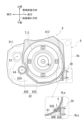
- FIG. 3 is a diagram of the case viewed from the second cover side.
- FIG. 4 is a diagram of the second cover viewed from the case side.
- FIG. 5 is a diagram of the second cover viewed from the front side of the vehicle.
- FIG. 6 is a diagram of the second cover viewed from the engine side.
- FIG. 7 is a diagram illustrating the arrangement of the control valve and oil cooler on the vehicle front side of the housing.
- FIG. 8 is a diagram illustrating an example of a hydraulic control circuit within a control valve.
- the power transmission device is a device having at least a power transmission mechanism, and the power transmission mechanism is, for example, at least one of a gear mechanism, a differential gear mechanism, and a speed reduction mechanism.
- the power transmission device 1 has a function of transmitting the output rotation of the engine, but the power transmission device 1 transmits the output rotation of at least one of the engine and the motor (rotating electric machine). It's fine as long as it's something you do.
- the term “control unit” in this specification means an inverter.
- “Overlapping in a predetermined direction” means that a plurality of elements are lined up in a predetermined direction, and has the same meaning as "overlapping in a predetermined direction.”
- the "predetermined direction” is, for example, an axial direction, a radial direction, a gravity direction, a vehicle running direction (vehicle forward direction, vehicle backward direction), or the like. If a drawing shows multiple elements (parts, parts, etc.) lining up in a predetermined direction, there is a sentence in the description explaining that they overlap when viewed in the predetermined direction. It can be considered as.
- “Do not overlap when viewed in a predetermined direction” and “offset when viewed in a predetermined direction” mean that multiple elements are not lined up in a predetermined direction, and "do not overlap in a predetermined direction” , is synonymous with the expression “offset in a predetermined direction”.
- the "predetermined direction” is, for example, an axial direction, a radial direction, a gravity direction, a vehicle running direction (vehicle forward direction, vehicle backward direction), or the like. If a drawing shows that multiple elements (parts, parts, etc.) are not lined up in a predetermined direction, there is a sentence in the description explaining that they do not overlap when viewed in a predetermined direction. It can be considered as.
- the first element (component, section, etc.) is located between the second element (component, section, etc.) and the third element (component, section, etc.) when viewed from a predetermined direction" means In this case, the first element can be observed to be between the second and third elements.
- the "predetermined direction" includes an axial direction, a radial direction, a direction of gravity, a vehicle running direction (vehicle forward direction, vehicle backward direction), and the like.
- vehicle forward direction vehicle backward direction
- the first element is located between the second element and the third element when viewed in the radial direction. It can be said that it is located.
- Axial direction means the axial direction of the rotating shaft of the components that constitute the power transmission device.
- Rotary direction means a direction perpendicular to the rotational axis of the components constituting the power transmission device.
- the parts are, for example, a motor, a gear mechanism, a differential gear mechanism, etc.
- Downstream side in the rotational direction means the downstream side in the rotational direction when the vehicle is moving forward or the rotational direction when the vehicle is moving backward. It is preferable to set it on the downstream side in the direction of rotation when the vehicle moves forward, which is often the case.
- “Vertical installation” of a control valve means that in the case of a control valve that has a basic configuration with a separate plate sandwiched between the valve bodies, the valve body of the control valve is placed horizontally with respect to the installation state of the power transmission device in the vehicle. This means that they are laminated in the same direction.
- the term "horizontal direction” as used herein does not mean the horizontal direction in a strict sense, but also includes cases where the stacking direction is tilted with respect to the horizontal line.
- vertical installation of a control valve means that the multiple pressure regulating valves (valve bodies) in the control valve are arranged in the vertical line VL direction based on the installation state of the power transmission device in the vehicle. This means that the valve is in place.
- a plurality of pressure regulating valves are arranged in the direction of the vertical line VL means that the pressure regulating valves in the control valve are arranged with their positions shifted in the direction of the vertical line VL.
- the plurality of pressure regulating valves do not need to be strictly lined up in a line in the vertical line VL direction.
- the plurality of pressure regulating valves are shifted in the direction of stacking of the valve bodies, and the vertical line VL They may be lined up in the same direction.
- the plurality of pressure regulating valves do not need to be lined up at intervals in the vertical line VL direction.
- the plurality of pressure regulating valves do not need to be adjacent to each other in the vertical line VL direction.
- pressure regulating valves lined up in the vertical line VL direction are arranged with their positions shifted in the stacking direction (horizontal line direction) of the valve body, the pressure regulating valves lined up in the vertical line VL direction are shifted when viewed from the stacking direction.
- This also includes cases where adjacent pressure regulating valves are provided in a positional relationship that partially overlaps.
- the multiple pressure regulating valves in the control valve are arranged in such a way that the moving direction of the valve body (spool valve) of the pressure regulating valve is along the horizontal direction.
- the moving direction of the valve body (spool valve) in this case is not limited to the horizontal direction in the strict sense.
- the moving direction of the valve body (spool valve) in this case is a direction along the rotation axis X of the power transmission device. In this case, the rotation axis X direction and the sliding direction of the valve body (spool valve) are the same.
- FIG. 1 is a schematic diagram illustrating the arrangement of a power transmission device 1 in a vehicle V.
- FIG. 2 is a schematic diagram illustrating a schematic configuration of the power transmission device 1. As shown in FIG.
- the power transmission device 1 is disposed at the front of the vehicle V between the left and right frames FR, FR.
- the housing HS of the power transmission device 1 includes a case 6, a side cover 7, a torque converter cover 8, and a front cover 9.
- a torque converter T/C As shown in FIG. 2, inside the housing HS, a torque converter T/C, a forward/reverse switching mechanism 2, a variator 3, a reduction mechanism 4, a differential device 5, an electric oil pump EOP, a mechanical oil pump MOP, and a control valve CV are provided. etc. are accommodated.
- a torque converter T/C is housed inside the torque converter cover 8.
- the output rotation of the engine ENG (drive source) is input to the forward/reverse switching mechanism 2 via the torque converter T/C.
- the rotation input to the forward/reverse switching mechanism 2 is input to the primary pulley 31 of the variator 3 in forward or reverse rotation.
- the rotation input to the primary pulley 31 is changed at a desired gear ratio, and the rotation is transferred to the output shaft 33 of the secondary pulley 32. is output from.
- the output rotation of the secondary pulley 32 is input to the differential device 5 (differential gear mechanism) via the reduction mechanism 4, and then transmitted to the drive wheels WH, WH via the left and right drive shafts 55A, 55B. .
- the speed reduction mechanism 4 includes an output gear 41, an idler gear 42, a reduction gear 43, and a final gear 45.
- the output gear 41 rotates together with the output shaft 33 of the secondary pulley 32.
- the idler gear 42 meshes with the output gear 41 so that rotation can be transmitted thereto.
- the idler gear 42 is spline-fitted to the idler shaft 44 and rotates together with the idler shaft 44.
- the idler shaft 44 is provided with a reduction gear 43 having a smaller diameter than the idler gear 42.
- the reduction gear 43 meshes with a final gear 45 fixed to the outer periphery of the differential case 50 of the differential device 5 so as to be able to transmit rotation.
- the forward/reverse switching mechanism 2 the torque converter T/C, and the output shaft of the engine ENG are arranged coaxially (concentrically) on the rotation axis X1 (first axis) of the primary pulley 31. Ru.
- the output shaft 33 of the secondary pulley 32 and the output gear 41 are coaxially arranged on the rotation axis X2 (second axis) of the secondary pulley 32.
- the idler gear 42 and the reduction gear 43 are coaxially arranged on a common rotation axis X3 (third axis).
- the final gear 45 and the drive shafts 55A and 55B are coaxially arranged on a common rotation axis X4 (fourth axis).
- these rotational axes X1 to X4 are set in a positional relationship in which they are parallel to each other.
- these rotational axes X1 to X4 will be collectively referred to as the rotational axis X of the power transmission device 1 (power transmission mechanism), if necessary.
- FIG. 3 is a plan view of the case 6 viewed from the torque converter cover 8 side.
- the front cover 9 is shown by imaginary lines.
- the front cover 9 is joined to a housing section 68 attached to the side surface of the case 6 on the vehicle front side, and forms a housing chamber S2 between the front cover 9 and the housing section 68 .
- illustration of the strainer 10 and mechanical oil pump MOP is omitted, and the vicinity of the connection parts 625 and 627 provided in the partition wall part 62 is shown.
- the case 6 includes a cylindrical peripheral wall portion 61 and a partition wall portion 62.
- the partition wall portion 62 is provided in a range that crosses the rotation axis (rotation axis X1 to rotation axis X4) of the power transmission mechanism.
- the partition wall 62 divides the space inside the peripheral wall 61 into two in the direction of the rotation axis X1.
- One side of the partition wall portion 62 in the direction of the rotation axis X1 is the first chamber S1, and the other side is the third chamber S3.
- the forward/reverse switching mechanism 2, the speed reduction mechanism 4, and the differential gear 5 are housed in the first chamber S1.
- the variator 3 is accommodated in the third chamber S3.
- the opening on the side of the first chamber S1 is sealed with a torque converter cover 8.
- the opening on the third chamber S3 side is sealed with the side cover 7.
- the space between the side cover 7 and the torque converter cover 8 (the first chamber S1, the third chamber S3) is provided with a chamber that is used for operating the power transmission device 1 and for lubricating the components of the power transmission device 1. oil is stored.
- the end surface of the case 6 on the torque converter cover 8 side forms a joint 611 with the torque converter cover 8.
- the joint portion 611 is a flange-shaped portion that surrounds the entire circumference of the opening of the partition wall portion 62 on the torque converter cover 8 side.
- a joint portion 811 (see FIG. 2) on the torque converter cover 8 side is joined to the joint portion 611 over the entire circumference.
- the case 6 and the torque converter cover 8 are connected with bolts (not shown) with their joints 611 and 811 joined together. As a result, the opening of the case 6 is kept sealed by the torque converter cover 8, and a closed first chamber S1 is formed.
- the partition wall portion 62 is located inside the joint portion 611.
- the partition wall portion 62 of the case 6 is provided in a direction substantially perpendicular to the rotation axis (rotation axes X1 to X4).
- the partition wall portion 62 is provided with through holes 621, 622, 624 and a support hole 623.
- the through hole 621 is formed around the rotation axis X1.
- a cylindrical support wall 631 that surrounds the through hole 621 and a peripheral wall 641 that surrounds the outer periphery of the support wall 631 at intervals are provided on the surface of the partition wall 62 on the first chamber S1 side (the front side in the drawing). It is being In FIG. 3, the support wall portion 631 and the peripheral wall portion 641 protrude toward the front side of the paper (toward the torque converter cover 8 side in FIG. 2).
- a region 651 between the support wall portion 631 and the peripheral wall portion 641 is a cylindrical space that accommodates a piston (not shown) of the forward/reverse switching mechanism 2, a friction plate (forward clutch, reverse brake), and the like.
- the input shaft 34 (see FIG. 2) of the primary pulley 31 is rotatably supported on the inner periphery of the support wall portion 631 via a bearing B.
- the through hole 622 is formed around the rotation axis X2.
- the rotation axis X2 is located diagonally above the rear side of the vehicle when viewed from the rotation axis X1.
- a cylindrical support wall portion 632 surrounding the through hole 622 is provided on the surface of the partition wall portion 62 on the first chamber S1 side (the front side in the drawing). In FIG. 3, the support wall portion 632 protrudes toward the front side of the paper (toward the torque converter cover 8 side in FIG. 2).
- the output shaft 33 (see FIG. 2) of the secondary pulley 32 is rotatably supported on the inner periphery of the support wall portion 632 via a bearing B.
- the support hole 623 is a bottomed hole formed around the rotation axis X3.
- the rotation axis X3 is located diagonally above the rear side of the vehicle when viewed from the rotation axis X1, and diagonally below the rear side of the vehicle when viewed from the rotation axis X2.
- a cylindrical support wall portion 633 surrounding the support hole 623 is provided on the surface of the partition wall portion 62 on the first chamber S1 side (the front side in the drawing). In FIG. 3, the support wall portion 633 protrudes toward the front side of the paper (toward the torque converter cover 8 side in FIG. 2).
- the support wall portion 633 surrounds the outer periphery of the support hole 623 at intervals.
- An idler shaft 44 (see FIG. 2) of the speed reduction mechanism 4 is rotatably supported on the inner periphery of the support wall portion 633 via a bearing B.
- the through hole 624 is formed around the rotation axis X4.
- the rotation axis X4 is located diagonally downward on the rear side of the vehicle when viewed from the rotation axis X1, diagonally downward on the rear side of the vehicle when viewed from the rotation axis X2, and diagonally downward on the rear side of the vehicle when viewed from the rotation axis X3. It is located diagonally below the front of the vehicle.
- a cylindrical support wall portion 634 surrounding the through hole 624 is provided on the surface of the partition wall portion 62 on the first chamber S1 side (the front side in the drawing). In FIG. 3, the support wall portion 634 protrudes toward the front side of the paper (toward the torque converter cover 8 side in FIG. 2). The support wall portion 634 surrounds the outer periphery of the through hole 624 at intervals.
- a differential case 50 (see FIG. 2) of the differential device 5 is rotatably supported on the inner periphery of the support wall portion 634 via a bearing B.
- a ring-shaped final gear 45 is fixed to the outer periphery of the differential case 50 when viewed from the direction of the rotation axis X4. Final gear 45 rotates around rotation axis X4 together with differential case 50.
- the strainer 10 is disposed below the arc-shaped peripheral wall portion 641 and in a region further forward of the vehicle than the final gear 45.
- a connecting portion 625 with the strainer 10 and a connecting portion 627 with the mechanical oil pump MOP are provided below the peripheral wall portion 641.
- the connection port 625a of the connection portion 625 and the connection port 627a of the connection portion 627 open in the same direction.
- a connection port 625a of the connection portion 625 communicates with an oil passage 626 provided within the partition wall portion 62.
- a connection port 627a of the connection portion 627 communicates with an oil passage 628 provided within the partition wall portion 62.
- the oil passages 626 and 628 extend linearly within the partition wall 62 toward the accommodating portion 68 (on the right side in the figure).
- the oil passage 626 is connected to an electric oil pump EOP housed in the housing portion 68 via an oil passage inside the case 6 .
- the oil passage 628 communicates with a control valve CV (see FIG. 2) installed inside the housing part 68 via an oil passage inside the case 6.
- boss portions 645 and 646 are provided at the lower portion of the partition wall portion 62 on the vehicle front side near the area where the oil passage 626 and the peripheral wall portion 61 intersect.
- the boss portions 645 and 646 are cylindrical members surrounding the first oil passage 635 and the second oil passage 636, respectively.
- the boss portions 645 and 646 protrude toward the front side of the paper (toward the torque converter cover 8 side).
- End surfaces 645a and 646a of the boss portions 645 and 646 on the front side in the drawing are flat surfaces located on the same plane as the joint portion 611 on the case 6 side.
- the boss portions 645 and 646 are arranged vertically in the vicinity of the peripheral wall portion 61.
- the boss portion 645 is located above the boss portion 646 in the vertical line VL direction.
- a housing portion 68 for the control valve CV is located on the side opposite to the boss portions 645 and 646 (on the right side in the figure) when viewed from the peripheral wall portion 61.
- a first oil passage 635 within the boss portion 645 and a second oil passage 636 within the boss portion 646 are each connected to a control valve CV.
- the opening direction of the first oil passage 635 and the second oil passage 636 is the same as the opening direction of the connection port 625a of the connection portion 625 and the connection port 627a of the connection portion 627 described above.
- the first oil passage 635 and the second oil passage 636 are provided with their openings facing toward the front side of the paper (the torque converter cover 8 side).
- FIG. 4 is a plan view of the torque converter cover 8 viewed from the case 6 side.
- the torque converter cover 8 is shown together with an oil cooler 20 attached to the outer periphery of the peripheral wall portion 81 of the torque converter cover 8 .
- illustration of the oil cooler 20 is omitted.
- the front cover 9 is shown by a virtual line in order to explain the positional relationship between the front cover 9 and the oil cooler 20.
- FIG. 5 is a side view of the torque converter cover 8 viewed from the front of the vehicle.
- the torque converter cover 8 is shown together with an oil cooler 20 attached to the side surface of the torque converter cover 8.
- FIG. 6 is a plan view of the torque converter cover 8 viewed from the engine ENG side.
- FIG. 6 the torque converter T/C housed inside the first area 825 is displayed superimposed on the torque converter cover 8 .
- the enlarged view of FIG. 6 schematically shows the positional relationship between the outer periphery of the peripheral wall 81 of the torque converter cover 8 and the oil cooler 20 attached to the outer periphery of the peripheral wall 81.
- the front cover 9 is shown by a virtual line in order to explain the positional relationship between the front cover 9 and the oil cooler 20.
- FIG. 7 is a diagram illustrating the arrangement of the control valve CV and the oil cooler 20 on the vehicle front side of the housing HS.
- the housing HS is shown as viewed from the front side of the vehicle, and the region of the joint portion 683 on the near side of the paper of the accommodating portion 68 is shown with cross hatching.
- the torque converter cover 8 includes a cylindrical peripheral wall portion 81 and a partition wall portion 82 .
- the partition wall portion 82 is provided in a range that crosses the rotation axis (rotation axis X1 to rotation axis X4) of the power transmission mechanism.
- the end surface of the peripheral wall portion 81 on the case 6 side serves as a joint portion 811 with the case 6.
- the joint portion 811 is a flange-shaped portion that surrounds the entire circumference of the opening of the partition wall portion 82 on the torque converter cover 8 side.
- a partition wall portion 82 is located inside the joint portion 811.
- the partition wall portion 82 is provided with through holes 821 and 824 and support holes 822 and 823.
- the partition wall portion 82 has a first region 825 and a second region 826.
- the first region 825 is a substantially circular region centered on the rotation axis X1.
- the first region 825 bulges toward the front side of the paper (towards the first chamber S1).
- the through hole 821 located approximately at the center of the first region 825 is formed around the rotation axis X1.
- the second region 826 is the region of the partition wall section 82 excluding the first region 825.
- the second region 826 is provided with support holes 822 and 823 and a through hole 824.
- boss portions 845 and 846 are provided at the lower portion on the front side of the vehicle.
- the boss portions 845 and 846 are cylindrical members surrounding the first connection path 835 and the second connection path 836, respectively.
- the boss portions 845 and 846 protrude toward the front side (the case 6 side) in the drawing.
- End surfaces 845a and 846a of the boss portions 845 and 846 on the near side in the drawing are flat surfaces located on the same plane as the joint portion 811 on the torque converter cover 8 side.
- the boss portions 845 and 846 are arranged vertically in the vicinity of the peripheral wall portion 81.
- the boss portion 845 is located above the boss portion 846 in the vertical line VL direction.
- the oil cooler 20 is located on the side opposite to the boss portions 645 and 646 (on the left side in the figure) when viewed from the peripheral wall portion 81.
- a first connection path 835 within the boss portion 845 and a second connection path 836 within the boss portion 846 are each connected to the oil cooler 20.
- the first connection path 835 and the second connection path 836 are provided with their openings facing the front side (case 6 side) in the drawing.
- the boss portions 845 and 846 are provided at positions where they are joined to the boss portions 645 and 646 on the case 6 side, respectively, when the torque converter cover 8 is assembled to the case 6.
- the first oil passage 635 in the boss part 645 and the second oil passage 636 in the boss part 646 are connected to the first oil passage 835 in the boss part 845 and the second oil passage 636 in the boss part 846, respectively. 2 connection path 836.
- boss portions 865 and 866 are provided on the side surface of the peripheral wall portion 81 on the vehicle front side.
- the boss portions 865 and 866 are cylindrical members surrounding the first connection path 835 and the second connection path 836, respectively.
- the first connection path 835 extends within the peripheral wall portion 81 of the torque converter cover 8 in the direction of the rotation axis X, and opens at the end faces of the boss portion 865 and the boss portion 845.
- the second connection path 836 extends within the peripheral wall portion 81 of the torque converter cover 8 in the direction of the rotation axis X, and opens at the end faces of the boss portion 866 and the boss portion 846.
- the boss portion 846 is located below the boss portion 845. Therefore, the second connection path 836 extends below the first connection path 835 in the rotation axis X direction. Note that the first connection path 835 and the second connection path 836 are bent at an intermediate position in the longitudinal direction. One end in the longitudinal direction of the first connection path 835 and the second connection path 836 opens toward the rotation axis X direction of the power transmission device 1 . The other end has an opening facing in a direction perpendicular to the rotation axis X of the power transmission device 1 (towards the front of the vehicle).
- the boss portions 865 and 866 protrude toward the front side of the drawing (vehicle front side). End surfaces 865a and 866a of the boss portions 865 and 866 on the near side in the drawing are flat surfaces located on the same plane.
- a rib 87 is provided above the boss portions 865 and 866 in the direction of the vertical line VL.
- the rib 87 is provided in a direction along the rotation axis X.
- Bolt boss portions 871, 871 having bolt holes 872 are provided on the end surface of the rib 87 on the vehicle front side.
- the bolt boss portions 871, 871 are provided at intervals in the longitudinal direction of the rib 87.
- Ribs 88 are also provided below the boss portions 865 and 866 in the vertical line VL direction.
- the rib 88 is provided in a direction along the rotation axis X1 direction.
- Bolt boss portions 881, 881 having bolt holes 882 are provided on the end surface of the rib 88 on the vehicle front side.
- the bolt boss portions 881, 881 are provided at intervals in the longitudinal direction of the rib 88.
- the upper bolt boss portions 871, 871 and the lower bolt boss portions 881, 881 protrude toward the front side of the vehicle. End surfaces 871a and 881a of the bolt boss portions 871 and 881 are flat surfaces located on the same plane.
- end surfaces 871a and 881a of bolt boss portions 871 and 881 and end surfaces 865a and 866a of boss portions 865 and 866 are located on straight line Lz along the vertical line VL direction.
- each end surface 865a, 866a, 871a, 881a located on the vertical line VL serves as a mounting surface for the oil cooler 20.
- the mounting surface (straight line Lz) of the oil cooler 20 is located on the rear side of the vehicle from a straight line L9 along a joint surface between the housing portion 68 and the front cover 9, which will be described later. Furthermore, the mounting surface (straight line Lz) of the oil cooler 20 intersects the straight line L9 above the oil cooler 20.
- the oil cooler 20 has a cubic-shaped main body part 201 and a plate part 202 that covers the surface of the main body part 201 on the torque converter cover 8 side (the right side surface in FIG. 4). As shown in FIG. 5, insertion holes 203 for bolts BL are provided at the four corners of the plate portion 202.
- the oil cooler 20 is fixed to the side surface of the torque converter cover 8 by screwing the bolts BL passing through the insertion holes 203 of the plate portion 202 into the bolt holes 872 and 882 of each bolt boss portion 871 and 881.
- An inlet 205 and an outlet 206 are opened on the surface of the oil cooler 20 facing the torque converter cover 8 .
- the inlet 205 and the first connecting path 835 communicate with each other
- the outlet 206 and the second connecting path 836 communicate with each other.
- a cooling water inlet 207 and an outlet 208 are provided on the end surface of the oil cooler 20 on the near side (vehicle front side) in the drawing.
- Oil OL supplied through the first connection path 835 flows into the main body portion 201 from the inlet 205 .
- the oil OL that has flowed into the main body portion 201 is discharged from the outlet 206 to the second connection path 836 .
- a cooling pipe (not shown) connecting the inlet 207 and the outlet 208 is provided inside the main body 201 .
- the oil OL is cooled by heat exchange between the cooling medium flowing through the cooling pipe and the oil OL flowing from the inlet 205 to the outlet 206 in the main body 201.
- the oil cooler 20 is provided at a lower portion of the torque converter cover 8 on the vehicle front side.
- the peripheral wall portion 81 of the torque converter cover 8 has a region on the vehicle front side in an arcuate shape along the outer periphery of the torque converter T/C, which is circular when viewed from the direction of the rotation axis X1. Therefore, as shown in the enlarged view of FIG.
- the oil cooler 20 is arranged such that at least a portion of the oil cooler 20 is located in the area a. Therefore, the oil cooler 20 is arranged without significantly protruding downward in the direction of the vertical line VL or forward in the longitudinal direction of the vehicle. This prevents the installation of the oil cooler 20 from significantly increasing the size of the power transmission device 1 in the vertical direction or in the longitudinal direction of the vehicle.
- the oil cooler 20 close to the peripheral wall portion 81, the length L of the boss portions 865 and 866 connected to the inlet 205 and the outlet 206 of the oil cooler 20 can be shortened.
- the oil passages (the first oil passage 635 and the first connection passage 835, and the second oil passage 636 and the second connection passage 836) connecting the oil cooler 20 and the control valve CV are The length can be made shorter.
- the oil passage resistance acting on the oil OL flowing through the oil passage can be reduced. This can be expected to reduce the load on the oil pump (electric oil pump EOP, mechanical oil pump MOP).
- the oil cooler 20 is provided in a positional relationship overlapping with the front cover 9 when viewed from the rotation axis X1 direction. In this state, the oil cooler 20 is arranged so as not to protrude further forward than the vehicle front side end surface 9a of the front cover 9 (see FIG. 3).
- the oil cooler 20 is provided in the lower part of the power transmission device 1 adjacent to the accommodating portion 68 on the case 6 side.
- a housing portion 68 is attached to the side surface on the front side of the vehicle.
- the housing portion 68 is provided with an opening facing toward the front side of the vehicle.
- the housing portion 68 is provided in a direction along the rotation axis X1.
- the accommodating portion 68 is formed to have a range in the rotation axis X1 direction extending from the area of the peripheral wall portion 61 of the case 6 to the side of the side cover 7.
- approximately half of the bottom wall portion 682 of the housing portion 68 on the engine ENG side is integrated with the peripheral wall portion 61.
- a substantially half region on the opposite side of the bottom wall portion 682 is provided on an extension of the peripheral wall portion 61 with a gap between it and the outer periphery of the side cover 7 .
- the housing portion 68 has a surrounding wall 681 that surrounds the entire outer periphery of a bottom wall portion 682 when viewed from the front side of the vehicle.
- the end surface of the surrounding wall 681 on the near side in the drawing forms a joint portion 683 with the front cover 9.
- the joint portion 683 is a flange-shaped portion that surrounds the entire circumference of the opening of the surrounding wall 681 on the front cover 9 side.
- a joint portion 911 on the front cover 9 side is joined to the joint portion 683 over the entire circumference.
- the accommodating portion 68 and the front cover 9 are connected with bolts (not shown) with their joint portions 683 and 911 joined together. As a result, the opening of the accommodating portion 68 is kept sealed by the front cover 9, forming a closed accommodating chamber S2.
- a straight line L9 along the joint surface between the joint 683 on the accommodating portion 68 side and the joint 911 on the front cover 9 side is inclined with respect to the vertical line VL.
- a control connector 98 is accommodated in the accommodation chamber S2.
- the control connector 98 is located on the vehicle front side of the control valve CV, and is arranged with the connection portion with the mating connector facing the engine ENG side (the front side in the drawing).
- a control valve CV and an electric oil pump EOP are housed in the housing chamber S2.
- the control valve CV has a basic configuration in which a separate plate 920 is sandwiched between valve bodies 921, 921.
- a hydraulic control circuit 95 (see FIG. 8) is formed inside the control valve CV.
- the hydraulic control circuit 95 is provided with a solenoid that is driven based on a command from a control device (not shown) and a pressure regulating valve (spool valve) that is operated by signal pressure generated by the solenoid.
- the control valve CV is vertically placed with the stacking direction of the valve bodies 921, 921 aligned with the vehicle front-rear direction (in the drawing, front-rear direction).
- the control valve CV is vertically placed so as to satisfy the following conditions.
- (a) A plurality of pressure regulating valves SP (spool valves) in the control valve CV are lined up in the vertical line VL direction (vertical direction) based on the installation state of the power transmission device 1 in the vehicle V,
- Pressure regulating valve The forward and backward movement direction Xp of SP (spool valve) is along the horizontal direction.
- control valve CV is vertically placed in the accommodation chamber S2 while preventing the forward and backward movement of the pressure regulating valve SP (spool valve) from being obstructed. Therefore, the storage chamber S2 is prevented from increasing in size in the longitudinal direction of the vehicle.
- the control valve CV has a substantially L-shape in which a notch 923 is provided in a rectangular valve body 921 when viewed from the front side of the vehicle.
- the cutout portion 923 is located at the lower part of the region overlapping with the side cover 7.
- An electric oil pump EOP is accommodated in the notch 923 when viewed from the front side of the vehicle.
- the electric oil pump EOP has a basic configuration in which a control section 931, a motor section 932, and a pump section 933 are arranged in series in the direction of the rotation axis Z1 of the motor.
- the electric oil pump EOP is provided with a rotation axis Z1 perpendicular to a rotation axis X of the power transmission device 1.
- the pump section 933 is located at the lowest part within the storage chamber S2.
- the suction port 933a and the discharge port 933b of the pump section 933 are located on the boundary side with the motor section 932, and are respectively connected to the oil passage in the case.
- the suction port 933a is connected to the strainer 10 via the case internal oil passage and the aforementioned oil passage 626 within the partition wall 62 (see FIG. 3).
- the strainer 10 is housed in a first chamber S1 that is separate from the housing chamber S2 of the control valve CV (see FIG. 3).
- the strainer 10 is arranged at a position shown by a broken line on the back side of the paper of the storage chamber S2 when viewed from the front side of the vehicle.
- the pump part 933 of the electric oil pump EOP is located at the lowest part in the storage chamber S2, so that the position of the suction port 933a of the pump part 933 and the strainer 10 in the vertical line VL direction becomes close to each other. I have to. Thereby, the length of the oil path connecting the strainer 10 and the suction port 933a of the electric oil pump EOP is minimized.
- the upper side of the control valve CV extends above the electric oil pump EOP.
- the electric oil pump EOP When viewed from the vertical line VL direction (rotational axis Z1 direction of the electric oil pump EOP), the electric oil pump EOP is provided in a positional relationship overlapping with the control valve CV.
- the frame FR of the vehicle V (see FIG. 1) is located on the side of the side cover 7, and there is no room to expand the housing HS in the vehicle width direction (horizontal line HL direction).
- the control valve CV and the electric oil pump EOP are not simply arranged in parallel, but the electric oil pump is placed in a notch 923 provided in the control valve CV. EOP is in place. This makes it possible to arrange the control valve CV and the electric oil pump EOP within the housing portion 68 without expanding the housing portion 68 in the vehicle width direction and without expanding the housing portion 68 in the longitudinal direction of the vehicle. ing.
- the housing HS of the power transmission device 1 is aligned in the vehicle width direction. This prevents large expansion in the longitudinal direction of the vehicle.
- the control valve CV has connection ports 65 and 66 with the oil passages (first oil passage 635, second oil passage 636) in the case described above.
- the connection ports 65 and 66 open at a position closer to the torque converter cover 8 (to the left in the figure).
- the oil cooler 20 is provided adjacent to the storage chamber S2. Therefore, the length of the oil passages (the first oil passage 635 and the first connection passage 835, and the second oil passage 636 and the second connection passage 836) connecting the control valve CV and the oil cooler 20 is made to be the shortest.
- An oil cooler 20 is positioned at.
- a hydraulic control circuit 95 in the control valve CV regulates the working hydraulic pressure of the power transmission mechanism (torque converter T/C, etc.) from the hydraulic pressure generated by the oil pump.
- the power transmission device 1 includes one mechanical oil pump MOP and one electric oil pump EOP as oil pumps. These oil pumps suck and pressurize the oil OL stored in the lower part of the housing HS, and supply it to the hydraulic control circuit 95 (see FIG. 8) in the control valve CV.
- FIG. 8 is a diagram illustrating an example of the hydraulic control circuit 95 in the control valve CV, and is a diagram showing a portion of the hydraulic control circuit 95 related to pressure regulation of the hydraulic pressure supplied to the torque converter T/C.
- the first pressure regulating valve 951 adjusts the line pressure PL from the oil pressure generated by the oil pump OP by adjusting the drain amount of the oil OL in the first pressure regulating valve 951 .
- the line pressure PL adjusted by the first pressure regulating valve 951 is regulated by the second pressure regulating valve 952 and then supplied to the lockup control valve 960 .
- Lockup control valve 960 adjusts lockup control pressure and supplies it to torque converter T/C according to a command from a control device (not shown). As a result, the lock-up clutch is switched between engagement and release.
- the line pressure PL adjusted by the first pressure regulating valve 951 is regulated by adjusting the amount of drain from the third pressure regulating valve 953, and then supplied to the switching valve 961.
- the switching valve 961 switches between supplying the oil OL supplied from the third pressure regulating valve 953 to the input port of the torque converter T/C and supplying the oil OL returned from the output port to the oil cooler 20 side. conduct.
- Oil OL flowing from the switching valve 961 toward the oil cooler 20 is supplied to the oil cooler 20 through the first oil passage 635 on the case 6 side and the first connection passage 835 on the torque converter cover 8 side.
- the oil OL cooled by the oil cooler 20 passes through the second connection path 836 and the second oil path 636 and is returned to the control valve CV.
- the oil OL returned to the control valve CV is supplied to parts of the power transmission device 1 that require lubrication, and lubricates the components of the power transmission device 1.
- the oil cooler 20 is provided so as to overlap the control valve CV disposed outside the housing HS (case 6) in the direction of the rotation axis X1 of the power transmission device 1.
- the control valve CV and the oil cooler 20 are arranged so as to protrude in the same direction from the same side surface of the housing HS.
- the control valve CV and the oil cooler 20 are arranged close to each other on the same side surface of the housing HS while protruding in the same direction. Therefore, the extent to which the power transmission device 1 becomes larger can be suppressed.
- the length of the oil passages (the first oil passage 635 and the first connection passage 835, and the second oil passage 636 and the second connection passage 836) connecting the control valve CV and the oil cooler 20 can be minimized. Thereby, the oil passage resistance acting on the oil OL flowing through the oil passage can be reduced.
- oil OL output from the output port of the torque converter T/C is supplied to the oil cooler 20 via the switching valve 961.
- the torque converter T/C When the vehicle V equipped with the power transmission device 1 is running, the torque converter T/C generates heat. Oil OL output from the output port of the torque converter T/C is quickly supplied to the oil cooler 20 and cooled.
- the oil path length from the torque converter T/C to the oil cooler 20 becomes longer, the distance through which the high temperature oil OL flows within the housing HS becomes shorter. If this happens, the housing HS will be heated by the high temperature oil OL. This increases the possibility that oil flowing through other oil passages within the housing HS will also be warmed.
- the oil cooler 20 Seen from the front side of the vehicle, the oil cooler 20 is located adjacent to the control valve CV on the vehicle front side of the torque converter T/C, so the oil path length from the torque converter T/C to the oil cooler 20 is It can be made shorter. This can reduce the possibility that the housing HS will be warmed by the high-temperature oil OL and the oil OL flowing through other oil passages will be warmed, as in the case where the oil passage length is long.
- the power transmission device 1 has the following configuration.
- the power transmission device 1 is A power transmission mechanism (torque converter T/C, forward/reverse switching mechanism 2, variator 3, deceleration mechanism 4, differential gear 5) that transmits the driving force from the engine ENG (drive source) to the drive wheels WH, WH; a housing HS that accommodates a power transmission mechanism; a control valve CV that controls the pressure of oil supplied to the power transmission mechanism; an oil cooler 20 (heat exchanger) that cools oil; a first chamber S1 that accommodates a power transmission mechanism; It has a storage chamber S2 (second chamber) in which the control valve CV is vertically arranged.
- Housing HS is Case 6 and A torque converter cover 8 (first cover) that is joined to the case 6 from the rotation axis X direction of the power transmission mechanism and forms a first chamber S1 between the case 6 and the case 6;
- a front cover 9 (second cover) that is joined to the case 6 from the front side of the vehicle when viewed from the direction of the rotation axis X of the power transmission mechanism and forms a storage chamber S2 (second chamber) between the front cover 9 and the case 6; has.
- the oil cooler 20 heat exchanger
- the oil cooler 20 is attached to the front of the torque converter cover 8 in the vehicle. When viewed from the direction of the rotation axis X of the power transmission mechanism, the oil cooler 20 is provided in a positional relationship such that at least a portion, preferably the entire portion thereof, overlaps with the control valve CV.
- the control valve CV is arranged in the storage chamber S2 different from the first chamber S1.
- a spatial margin is created within the case 6. Therefore, the layout inside the case 6 is improved.
- at least a portion, preferably the entire oil cooler 20 overlaps the control valve CV disposed outside the case 6 (on the vehicle front side of the housing HS) in the direction of the rotation axis X of the power transmission mechanism. That is, when viewed from the direction of the rotation axis X, the control valve CV and the oil cooler 20 are provided on the vehicle front side of the housing HS in a positional relationship in which they have at least an overlapping portion.
- control valve CV and the oil cooler 20 are arranged adjacent to each other in the rotation axis X1 direction of the power transmission device 1 while protruding in the same direction on the same side surface of the housing HS.
- the oil cooler 20 can be provided adjacent to the control valve CV by utilizing the range of the protrusion height of the control valve CV (front cover 9) that protrudes from the side surface of the housing HS.
- the control valve CV and the oil cooler 20 are provided on different sides of the housing HS, the power transmission device 1 becomes larger in different directions, resulting in an increase in size.
- the control valve CV and the oil cooler 20 are provided on the same side surface of the housing HS, and at least a portion, preferably the entirety, of the oil cooler 20 overlaps with the control valve CV when viewed from the direction of the rotation axis X1 of the power transmission device 1. By arranging them in a positional relationship, the directions for increasing size are aligned. Thereby, the extent to which the power transmission device 1 becomes larger can be suppressed depending on the extent of the difference between the oil cooler 20 and the control valve CV. Further, for example, if the control valve CV is disposed on the vehicle front side surface of the housing HS and the oil cooler 20 is disposed on the rear side surface, the cooling efficiency of the oil OL may be impaired. As described above, by providing the control valve CV and the oil cooler 20 on the same side of the housing HS, it is expected that the cooling efficiency of the oil OL will be improved.
- the torque converter cover 8 is a converter housing that houses the torque converter T/C. When viewed from the direction of the rotation axis X of the power transmission mechanism, the torque converter cover 8 has a peripheral wall portion 81 surrounding the outer periphery of the torque converter T/C.
- the oil cooler 20 is attached to the lower portion of the peripheral wall portion 81 on the vehicle front side in the vertical line VL direction based on the installed state of the power transmission device 1 in the vehicle V.
- the power transmission device 1 includes a first power transmission mechanism and a second power transmission mechanism.
- the housing HS includes a torque converter cover 8 (converter housing) that accommodates the first power transmission mechanism (torque converter T/C), It has a case 6 that accommodates the second power transmission mechanism (forward/reverse switching mechanism 2, variator 3, deceleration mechanism 4, differential device 5).
- the oil cooler 20 is attached to the torque converter cover 8.
- the control valve CV is attached to the housing part 68 of the case 6.
- the case 6 and the torque converter cover 8 are adjacent to each other in the direction of the rotation axis X of the power transmission device 1.
- the oil cooler 20 can be installed on the side surface of the torque converter cover 8 even if there is no space for installing the oil cooler 20 on the side surface of the case 6.
- the oil cooler 20 can be provided adjacent to the control valve CV so as to overlap with the control valve CV when viewed from the rotation axis X direction. Therefore, the extent to which the power transmission device 1 increases in size in the radial direction of the rotation axis X can be suppressed.
- bolt boss portions 871 and 881 which are attachment portions for the oil cooler 20, are provided on the vehicle front side surface. When viewed from the direction of the rotation axis (see Figure 4).
- the oil cooler 20 can be arranged without significantly protruding toward the front of the vehicle. Thereby, the extent to which the power transmission device 1 becomes larger toward the front of the vehicle can be suppressed.
- the bolt boss portions 871 and 881 which are the mounting portions of the oil cooler 20, are located below the rotation axis X1 of the torque converter T/C.
- the arc-shaped circumferential wall portion 81 along the outer periphery of the torque converter T/C is located on the vehicle front side and from the rotation axis X1 of the torque converter T/C.
- the oil cooler 20 is arranged in the lower region a (see FIG. 6). At least a portion of the oil cooler 20 is arranged in area a.
- the oil cooler 20 can be arranged without significantly protruding toward the front of the vehicle. Furthermore, the length of piping connecting the oil cooler 20 to the first connection path 835 and the second connection path 836 can be minimized or omitted. Thereby, the length of the oil path (the first connection path 835 and the first oil path 635, and the second connection path 836 and the second oil path 636) from the oil cooler 20 to the control valve CV can be shortened. Thereby, the oil passage resistance acting on the oil OL flowing through the oil passage can be reduced. This can be expected to reduce the load on the oil pump (electric oil pump EOP, mechanical oil pump MOP).
- control valve CV and the oil cooler 20 are provided on the side surface on the front side of the vehicle (the same side surface on the front side of the vehicle).
- the power transmission device 1 includes an electric oil pump EOP provided in the storage chamber S2.
- the electric oil pump EOP is provided in an overlapping positional relationship with the control valve CV and the oil cooler 20.
- the electric oil pump EOP, the control valve CV, and the oil cooler 20 overlap and are provided on the vehicle front side of the housing HS.
- the oil cooler 20 can be housed within the range of the protruding height of the accommodation chamber S2 that accommodates the electric oil pump EOP and the control valve CV.
- enlargement of the rotation axis X1 of the power transmission device 1 in the radial direction (vehicle front side) can be suitably suppressed.
- the case 6 When viewed from the front side of the vehicle, the case 6 is provided with a housing portion 68 that surrounds the area of the housing chamber S2 (second chamber) and has an opening facing the front side of the vehicle.
- the storage chamber S2 is formed by closing the opening of the storage portion 68 with the front cover 9.
- the oil cooler 20 is located outside the storage chamber S2 when viewed from the front side of the vehicle, and the oil cooler 20 is provided in a positional relationship that overlaps the storage portion 68 and the front cover 9 when viewed from the direction of the rotation axis It is being
- the storage chamber S2 containing the control valve CV and the oil cooler 20 are provided in parallel in the direction of the rotation axis X of the power transmission mechanism on the vehicle front side of the housing HS.
- the control valve CV is provided at the lower part of the housing HS, the power transmission device 1 becomes larger in size in the vertical line VL direction by the control valve CV.
- the control valve CV When installing the control valve CV in the accommodation chamber S2 provided on the vehicle front side of the housing HS, the pressure regulating valve in the hydraulic control circuit 95 needs to be arranged along the horizontal direction. Therefore, the control valve CV is placed vertically (see FIG. 7). Thereby, when providing the control valve CV in the accommodation chamber S2, it is possible to suppress the extent to which the power transmission device 1 becomes larger toward the front of the vehicle. By providing the oil cooler 20 at a position adjacent to the vertically placed control valve CV, it is possible to suppress the extent to which the power transmission device 1 increases in size toward the front of the vehicle.
- control valve CV and the electric oil pump EOP are lined up in the direction of the rotation axis X of the power transmission mechanism.
- the control valve CV is located closer to the oil cooler 20 than the electric oil pump EOP.
- the power transmission device 1 includes a side cover 7 (third cover) that is joined to the case 6 from the direction of the rotation axis X of the power transmission mechanism and forms a third chamber S3 between the side cover 7 and the case 6.
- the side cover 7 is joined to the case 6 from the side opposite to the torque converter cover 8 in the direction of the rotation axis X of the power transmission mechanism.
- the housing portion 68 extends along the rotation axis X of the power transmission mechanism in a direction away from the oil cooler 20 and extends to the side of the side cover 7 .
- the accommodating portion 68 is provided in a range overlapping with the case 6 and the side cover 7 when viewed from the radial direction of the rotation axis X (vehicle front side). Therefore, the accommodating portion 68 can be provided without protruding laterally beyond the side cover 7. Thereby, it is possible to suitably prevent the power transmission device 1 from increasing in size in the direction of the rotation axis X.
- the case 6 is provided with a first oil passage 635 connected to the control valve CV and a second oil passage 636 connected to the control valve CV.
- the torque converter cover 8 is provided with a first connection path 835 that connects to the oil cooler 20 and a second connection path 836 that connects to the oil cooler 20 (see FIG. 7).
- the first connection path 835 and the first oil path 635 are arranged to face each other in the joining direction of the torque converter cover 8 and the case 6.
- the second connection path 836 and the second oil path 636 are arranged to face each other in the joining direction of the torque converter cover 8 and the case 6.
- connection between the control valve CV and the oil cooler 20 is completed when the connection between the torque converter cover 8 and the case 6 is completed. This facilitates the connection between the control valve CV and the oil cooler 20, thereby improving the efficiency of the assembly work of the power transmission device 1.
- a boss portion 865 which is a connection portion on the first connection path 835 side, is provided at a portion facing the oil OL inlet 205 (oil inlet) in the oil cooler 20 (see FIG. 5).
- a boss portion 866 which is a connection portion on the second connection path 836 side, is provided at a portion of the oil cooler 20 facing the oil OL outlet 206 (oil outlet) (see FIG. 5).
- An end surface 865a, which is the connection part of the boss part 865 with the oil cooler 20, and an end face 866a, which is the connection part with the oil cooler 20, of the boss part 866, are on the same plane orthogonal to the direction in which the oil cooler 20 is attached to the torque converter cover 8. (straight line Lz: see FIG. 4).
- the oil cooler 20 is assembled to the torque converter cover 8 from the front side of the vehicle. With the above configuration, when the oil cooler 20 is assembled to the torque converter cover 8, the end surface 865a of the boss portion 865 and the end surface 866a of the boss portion 866 are joined to the inlet 205 and outlet 206 on the oil cooler 20 side, respectively. Then, the connection between the oil cooler 20 and the first connection path 835 and the second connection path 836 is completed. This facilitates the connection between the torque converter cover 8 and the oil cooler 20, thereby improving the efficiency of the assembly work of the power transmission device 1.
- the first connection path 835 and the second connection path 836 are arranged vertically in the vicinity of the side surface of the vehicle front side region (the side surface on the oil cooler 20 side) of the peripheral wall portion 81. (See Figure 4). In the case 6, the first oil passage 635 and the second oil passage 636 are arranged vertically in the vicinity of the vehicle front side region of the peripheral wall portion 61 (the side surface on the control valve CV side) (see FIG. 3). .
- the length of the oil passages (the first oil passage 635 and the first connection passage 835, and the second oil passage 636 and the second connection passage 836) connecting the control valve CV and the oil cooler 20 can be minimized. Can be done. Thereby, the oil passage resistance acting on the oil OL flowing through the oil passage can be reduced. Therefore, a reduction in the load on the oil pump (electric oil pump EOP, mechanical oil pump MOP) can be expected.
- the power transmission device 1 transmits the rotation of the engine ENG to the drive wheels WH, WH is illustrated, but the power transmission device 1 transmits the rotation of the engine ENG and the motor (rotating electric machine).
- the rotation may be transmitted to the drive wheels WH, WH.
- a one-motor, two-clutch type (the motor is arranged between the engine ENG and the power transmission device, the first clutch is arranged between the engine ENG and the motor, and the second clutch is arranged inside the power transmission device 1)
- It may also be a power transmission device of the following type.
- the power transmission device 1 has a speed change function, but the power transmission mechanism does not have a speed change function and simply decelerates (or may speed up). It's okay. If the power transmission device does not have a speed change function and is configured to decelerate the rotation of the motor and transmit it to the drive wheels WH, the oil OL for cooling the motor and the deceleration A hydraulic control circuit for supplying oil OL for lubricating the mechanism is placed in the storage chamber S2 together with the electric oil pump EOP. Further, in the above embodiment, the control unit of the power transmission device 1 is provided with the control valve CV, but the power transmission device 1 does not have a speed change mechanism, and the drive source is not the engine ENG. In the case of a motor (rotating electric machine), it may be a control unit including an inverter or the like that drives and controls the motor.
Abstract
Le problème décrit par la présente invention est de supprimer une augmentation de la taille d'un dispositif de transmission de puissance. La solution selon l'invention porte sur un dispositif de transmission de puissance pour un véhicule, qui comprend : un logement qui reçoit un mécanisme de transmission de puissance ; une soupape de commande qui commande la pression de l'huile fournie au mécanisme de transmission de puissance ; un échangeur de chaleur qui refroidit l'huile ; une première chambre qui reçoit le mécanisme de transmission de puissance ; et une seconde chambre dans laquelle la soupape de commande est disposée verticalement, le logement ayant un boîtier, un premier couvercle qui est relié au boîtier à partir de la direction d'axe de rotation du mécanisme de transmission de puissance et forme la première chambre conjointement avec le boîtier et un second couvercle qui est relié au boîtier à partir d'un côté avant de véhicule tel que vu depuis la direction d'axe de rotation du mécanisme de transmission de puissance et forme une seconde chambre conjointement avec le boîtier, l'échangeur de chaleur est fixé au premier couvercle à partir du côté avant de véhicule et l'échangeur de chaleur est disposé dans une relation de position chevauchant la soupape de commande tel que vu depuis la direction d'axe de rotation du mécanisme de transmission de puissance.
Applications Claiming Priority (2)
| Application Number | Priority Date | Filing Date | Title |
|---|---|---|---|
| JP2022-047605 | 2022-03-23 | ||
| JP2022047605 | 2022-03-23 |
Publications (1)
| Publication Number | Publication Date |
|---|---|
| WO2023182446A1 true WO2023182446A1 (fr) | 2023-09-28 |
Family
ID=88101689
Family Applications (1)
| Application Number | Title | Priority Date | Filing Date |
|---|---|---|---|
| PCT/JP2023/011609 WO2023182446A1 (fr) | 2022-03-23 | 2023-03-23 | Dispositif de transmission de puissance |
Country Status (1)
| Country | Link |
|---|---|
| WO (1) | WO2023182446A1 (fr) |
Citations (5)
| Publication number | Priority date | Publication date | Assignee | Title |
|---|---|---|---|---|
| JPH0458652U (fr) * | 1990-09-28 | 1992-05-20 | ||
| JP2012026462A (ja) * | 2010-07-20 | 2012-02-09 | Jatco Ltd | 自動変速機 |
| JP2016044712A (ja) * | 2014-08-20 | 2016-04-04 | トヨタ自動車株式会社 | 車両用変速機 |
| JP2017133594A (ja) * | 2016-01-28 | 2017-08-03 | アイシン精機株式会社 | 流体ポンプユニット |
| JP2017187059A (ja) * | 2016-04-01 | 2017-10-12 | トヨタ自動車株式会社 | 動力伝達装置 |
-
2023
- 2023-03-23 WO PCT/JP2023/011609 patent/WO2023182446A1/fr active Search and Examination
Patent Citations (5)
| Publication number | Priority date | Publication date | Assignee | Title |
|---|---|---|---|---|
| JPH0458652U (fr) * | 1990-09-28 | 1992-05-20 | ||
| JP2012026462A (ja) * | 2010-07-20 | 2012-02-09 | Jatco Ltd | 自動変速機 |
| JP2016044712A (ja) * | 2014-08-20 | 2016-04-04 | トヨタ自動車株式会社 | 車両用変速機 |
| JP2017133594A (ja) * | 2016-01-28 | 2017-08-03 | アイシン精機株式会社 | 流体ポンプユニット |
| JP2017187059A (ja) * | 2016-04-01 | 2017-10-12 | トヨタ自動車株式会社 | 動力伝達装置 |
Similar Documents
| Publication | Publication Date | Title |
|---|---|---|
| US10539071B2 (en) | Vehicle drive device | |
| JP5669878B2 (ja) | ハイブリッド車両の動力伝達装置 | |
| US9447864B2 (en) | Vehicle drive device | |
| KR101470726B1 (ko) | 트랜스미션 케이스용 주형 구조 및 트랜스미션 케이스 | |
| US10183567B2 (en) | Vehicle drive device | |
| JP5853761B2 (ja) | 駆動力伝達装置 | |
| JP3714845B2 (ja) | 変速機ユニット | |
| JP5644999B2 (ja) | ハイブリッド電気自動車のクラッチ及びモータハウジング構造 | |
| WO2023182446A1 (fr) | Dispositif de transmission de puissance | |
| WO2023182445A1 (fr) | Dispositif de transmission de puissance | |
| JPH0573236U (ja) | サブユニットを駆動するための伝動装置のための多チャンネル支持体 | |
| WO2023182444A1 (fr) | Dispositif de transmission de puissance | |
| WO2023182450A1 (fr) | Dispositif de transmission de puissance | |
| WO2023182447A1 (fr) | Dispositif de transmission de puissance | |
| WO2023182455A1 (fr) | Dispositif de transmission de puissance | |
| WO2023182452A1 (fr) | Dispositif de transmission de puissance | |
| WO2024004407A1 (fr) | Circuit hydraulique | |
| JP2023141341A (ja) | 動力伝達装置 | |
| WO2023182448A1 (fr) | Dispositif de transmission de puissance et dispositif hydraulique | |
| WO2023182456A1 (fr) | Dispositif de transmission de puissance | |
| WO2023182454A1 (fr) | Dispositif de transmission de puissance | |
| WO2023182453A1 (fr) | Dispositif de transmission de puissance | |
| WO2023182451A1 (fr) | Dispositif de transmission de puissance | |
| JP2024040625A (ja) | 電動アクスルの冷却構造 | |
| KR20230039081A (ko) | 변속기 |
Legal Events
| Date | Code | Title | Description |
|---|---|---|---|
| 121 | Ep: the epo has been informed by wipo that ep was designated in this application |
Ref document number: 23775040 Country of ref document: EP Kind code of ref document: A1 |
|
| DPE1 | Request for preliminary examination filed after expiration of 19th month from priority date (pct application filed from 20040101) |